Controllable Sliding Bearings and Controllable Lubrication Principles—An Overview †

Department of Mechanical Engineering, Technical University of Denmark, DK-2800 Kongens Lyngby, Denmark
†
This paper is an extended version of the paper published in 16th EDF-PPRIME conference.
Lubricants 2018, 6(1), 16; https://doi.org/10.3390/lubricants6010016
Submission received: 22 November 2017
/
Revised: 3 January 2018
/
Accepted: 15 January 2018
/
Published: 7 February 2018
(This article belongs to the Special Issue Friction and Lubrication of Sliding Bearings)
Abstract
:Hydrodynamic and aerodynamic lubrication regimes in their controllable forms have been intensively investigated over the last two decades. With the aim of reducing friction and improving thermal, static, and dynamic characteristics of radial sliding bearings, different types of electro-mechanical actuators have been coupled to such bearings. Depending on (i) the actuator type; (ii) the actuation principle, i.e., hydraulic, pneumatic, piezoelectric or magnetic among others; and (iii) how such an actuator is coupled to the sliding bearings, different regulation and control actions of fluid film pressure and lubricant flow can be obtained. The most common actions are: (a) the control of the injection pressure to modify the fluid film pressure statically as well as dynamically; (b) the adjustment of the angle and direction of injection flow (mostly passive action); (c) the control of the sliding bearing gap and its preload via moveable and compliant sliding surfaces; and (d) the control of the lubricant viscosity. All four parameters, i.e., pressure, flow (velocity profiles), gap and viscosity, are explicit parameters in the modified form of Reynolds’ equations for active lubrication. In this framework, this paper gives one main original contribution to the state-of-the-art of radial sliding bearings and controllable lubrication: a comprehensive overview about the different types of controllable sliding bearings and principles used by several authors. The paper ends with some conclusive remarks about advantages and drawbacks of the different design solutions for controllable sliding bearings and the main challenges to be overcome towards industrial applications.
1. Introduction
Industry 4.0 can be defined as the overlay of several technological developments involving products as well as processes. Industry 4.0 refers to the so-called cyber-physical systems and theses systems portraying a tight integration of physical and digital workflows [1], meaning that the physical steps of a production line are controlled by computer-based processes. Cyber-physical systems combine mechanics, electronics, computation, and capacity of data storage and use the internet as a communication medium [2]. Frequently Industry 4.0 is compared to with “proceeding disruptive increases in production” [3] such as three industrial revolutions based on mechanization, electrification and automation, changing the industrial production all over the world. These revolutions, like Industry 4.0, were started by the synergetic interaction among several technological progresses, culminating in new forms of production [4]. One can argue if Industry 4.0 should be seen as revolutionary or evolutionary [5], but it does not change the fact that Industry 4.0 will significantly change the innovation of products, supply chains, business models and business processes. In this framework, many companies have difficulties evaluating and judging the manifold developments and concepts involved under Industry 4.0 to define their own corporate strategies, as very well pointed out by Beckert [6].
Industry 4.0 embraces a set of technologies enabling smart products. Smart products are characterized by the capability of performing computations, storing data, communicating and interacting with their environment [7,8]. Fluid film bearing technology is nowadays witnessing an explosive expansion of active magnetic bearing technology, a typical so-called smart product. Some of the limitations and drawbacks associated to fluid film bearing technology could be overcome by combining fluid film bearings with sensing, control and signal processing techniques, lending them “smartness”, “multi-functionality” and “higher reliability” [9]. In such a framework, it is important to evaluate the state-of-the-art of controllable fluid film bearings, which fit perfectly within Industry 4.0 and have been investigated over the last two decades but have not yet found their space in industrial applications, despite several promising theoretical and experimental achievements.
With the aim of monitoring, predicting and controlling sliding bearings’ thermal, static and dynamic characteristics several types of sensing systems and electro-mechanical actuators—hydraulic, pneumatic, piezoelectric or magnetic, among others—have been coupled to such bearings allowing for different regulation and control strategies of pressure, lubricant flow and bearing clearance.
2. Strategies for Rendering Adaptability and Multi-Functionality to Sliding Bearings
Controllable sliding bearings (CSBs) are designed in a “synergistic relationship” to different types of electromechanical actuators [10,11,12] and sensing systems. For example, oil or water lubricated bearings are normally connected to servo-valves and hydraulic servo-systems [13,14,15], while gas or air lubricated bearings use piezoelectric actuators and pneumatic systems [16,17,18]. Direct and indirect actions of control forces onto the rotating shaft can occur either via bearing housing and bushing [19,20,21,22,23,24,25,26,27,28,29] or via bearing clearance [13,14,15,16,17,18,27]. The control actions influence fundamentally four parameters: either the bearing gap function h(θ) [21,22,23,24,25,26] and its gradient dh/dθ [23,24,25], or the fluid viscosity μ [30,31,32], or the fluid film pressure field p(θ) [13,14,15,16,17,18,27]. All four parameters are directly and explicitly written in the Reynolds and Energy equations and significantly affect the bearing properties. The possibility of actively sensing and controlling the behavior of such parameters allows for engineering smart design solutions and significant performance improvements, such as: (a) increase in load capacity; (b) increase of rotational speed ranges, and consequently production, due to improvements of controlled lateral dynamics of rotors; (c) reduction of friction and temperature and consequently enhancement of energy savings. Table 1 gives an overview of some innovative strategies for rendering adaptability and multi-functionality to sliding bearings over the last three decades.
Table 1 could certainly be expanded, but illustrates clearly the effort of several researchers pursuing their own ideas toward adjustable/adaptable/controllable fluid film bearings. Some of the ideas and design solutions have apparently not evolved, hence no further documentation can be found in the literature. Others are still under theoretical and experimental investigations and are well documented. One example of the design solutions that have evolved over the past decades is the controllable/active lubrication [13]. The technology is becoming mature and the next sections of this manuscript will be devoted to reporting some of its main achievements and challenges.
3. Controllable Lubrication Principles Applied to Sliding Bearings
Before reporting achievements and challenges it is important to define “active” and “controllable” lubrication. When the hydrostatic and the hydrodynamic lubrication regimes are simultaneously combined in a sliding bearing, one refers to hybrid lubrication. While the hydrodynamic lubrication regime is fundamentally driven by the journal angular velocity, the hydrostatic lubrication regime is driven by an external source of pressurization, i.e., a high-pressure pump. Orifices and pockets are normally machined over the bearing surface and directly connected to the high-pressure unit by means of pipelines. The pair of orifices is circumferentially machined around the bearing surface, normally 180 degrees from each other. Through the orifices, the pressurized lubricant reaches the bearing gap, influences the lubricant film pressure responsible for the separation of the rotating surface from the stationary one, and carries the journal loads. When part of the hydrostatic pressure is dynamically modified by means of hydraulic servo systems or piezoelectric actuators, one refers to controllable lubrication. Such a lubrication regime is realized by further including a servo-valve or piezoelectric actuators between the high-pressure unit and a pair of orifices. Through the servo-valve or piezoelectric actuator input signal, the lubricant pressure and flow through the pair of orifices are electronically modified, generating controllable lubricant film pressures and hence controllable forces. It is important to highlight that the controllable lubrication is regulated by a predefined input signal sent to the servo-valve or piezoelectric actuator, which might not utilize any kind of feedback signal. When sensing systems (for example based on a set of eddy-current displacement sensors) are installed in order to detect the lateral movements of the journal and their signals are used to build a feedback control law for the input signal of the servo-valve or piezoelectric actuator, one refers to active lubrication. If air/gas (compressible fluid) is used instead of oil/water (uncompressible), one refers to aerostatic, aerodynamic, hybrid, controllable and active lubrication. The pressurized fluid flow can be injected either orthogonally, or tangentially, or angled to the sliding surface.
3.1. From Aerostatic, Aerodynamic and Hybrid to Controllable and Active Gas Bearings
Two of the most pronounced drawbacks of radial gas bearings, the low load capacity and the lack of damping, can be overcome by means of control techniques, as discussed in this section. Figure 1 illustrates design details of a controllable radial sliding bearing using piezoelectric actuation to control the injection of lubricant (air) and the test bench, where the lateral dynamics of a flexible rotor is considerably improved by active lubrication as reported in [17,18]. The test rig is composed of a rotor supported by two types of bearings, a ball bearing (Figure 1a: 3) and a gas bearing (Figure 1a: 5). A gas turbine (Figure 1a: 1) drives a flexible shaft (Figure 1a: 4) connected to a rigid disc (Figure 1a: 6) with the aid of flexible couplings (Figure 1a: 2). The rigid disc (Figure 1a: 6) is mounted to the end of the flexible shaft. The lateral movements of the rigid disc are detected by two contactless eddy-current proximity sensors (Figure 1a: 8) positioned orthogonally to each other around the disc. Four piezoelectric actuators (Figure 1a: 7) are used to build a controllable gas bearing.
The lack of damping of radial gas bearings leads to high vibration levels of a rotor supported by this type of bearing, especially when crossing critical speeds. It is definitely not a trivial task to control bending modes of flexible rotors on gas bearings. In order to reduce high vibration levels, the controllable and the active gas lubrication principles are theoretically as well as experimentally demonstrated in [16,39,40], using several feedback control laws and control strategies. For the active case shown in Figure 2a, a simple optimal proportional controller is aided by feeding back the eddy-current displacement sensor signals (elements, Figure 1a: 8). The lateral response of the disc (element, Figure 1a: 6) due to impulsive excitation is illustrated for the horizontal and vertical directions, with and without the control action. In Figure 2, a comparison of theoretical and experimental results is also shown, giving a glance at the usefulness of the developed multi-physical models thoroughly investigated and documented in [16,18,39,40]. Theoretical and experimental results show a significant increase in the damping ratio, enabling the flexible (and relatively heavy) rotor to run safely across the critical speeds (without significant vibration amplifications) and extending its operational range 50% over the first critical speed without any instability problems. The damping ratio associated to the first flexural bending mode is increased by a factor of nine in comparison to the hybrid lubrication (without feedback control) as documented in [40,41,42]. It is important to highlight that a further increase of rotor angular velocity is not limited by new instability problems caused by fluid film forces but by large lateral vibrations associated with a second resonance in which the flexible rotor and turbine connected by the flexible coupling vibrate out-of-phase. The test rig is unfortunately composed of one single active sliding bearing, aiming at testing the active lubrication principle using compressible fluids. Observability and controllability analyzes reveal that this coupled mode shape can be detected by sensors installed at the disc location; nevertheless, it cannot be controlled using one single active sliding bearing.
3.2. From Hydrostatic, Hydrodynamic and Hybrid to Controllable and Active Oil Bearings
Tilting-pad journal bearings are a special type of sliding bearings. Even though they are commonly used in high speed turbomachinery applications due to their better dynamic stability properties in comparison to other types of sliding bearings, they lack damping at high speeds. With the aim of overcoming this drawback, sensing and control systems can be adapted to them, as is illustrated in Figure 3a,b, rendering multi-functionality, adaptability and smartness. The contactless inductive displacement sensors (Figure 3a: 1 and 2) measure the lateral vibrations of the rotor in the orthogonal directions, i.e., vertical and horizontal directions respectively. The accelerometer (Figure 3a: 3) attached to the bearing housing captures the horizontal vibrations of the bearing housing. To control the pressurized oil injection flow into the bearing gap, two servo valves (Figure 3a: 4 and 5) are used. The pressurized oil flows through the channels (Figure 3b: 8 and 9) into the bearing gap utilizing orifices machined in the middle of the pad surfaces. Such orifices are normally used in industrial bearings for hydrostatic lubrication during startup conditions. The channel (Figure 3b: 8) is connected to servo valves (Figure 3a: 4) and the channel (Figure 3b: 9) with the servo valve (Figure 3a: 5). Exploring the differential principle active control forces are generated. The oil injection will occur with an angle of 45 degrees from the horizontal or vertical directions, because the pads are mounted in a load-between-pads configuration. Such an oil injection will be controlled using the information coming from the sensor signals (Figure 3a: 1, 2, 3) and others mounted along the flexible rotating shaft. It is important to highlight that the bearing shall be able to operate both passively and actively. The conventional hydrodynamic lubrication is passive and will always be present. It uses the pipeline connector (Figure 3a: 6) and channel (Figure 3b: 7), where oil is fed into the bearing at low pressures. Four orifices are machined between the four tilting-pads and they are connected to the channel (Figure 3b: 7). An experimental setup composed of a flexible rotor–bearing system excited by an electromagnetic shaker and controlled by the active sliding bearing is shown in Figure 3c.
Experimental frequency response functions (FRFs) of the disc in the vertical and horizontal directions are depicted in Figure 4. Two controllers, i.e., an empirically-tuned PID controller and a model-based synthesized LQG regulator, are tested. The LQG control gains are calculated aided by a multi-physical mathematical model, which links solid mechanics, fluid dynamics, material science and control theory. In order words, the lateral dynamics of flexible rotating shaft and disc is described by an FE model [43]. The nonlinear fluid film forces are obtained by solving the modified Reynolds equations and energy equation via finite difference method [44,45]. The dynamics of the servo-valves is described by the second order differential equations and coupled to the global nonlinear dynamic model [46]. After calculating the rotor equilibrium position due to static loading, the system of nonlinear equations is linearized and the fluid film forces are represented by equivalent springs and dampers. Aided by the linearized mathematical model, written in its state–space form, classical control theory is used and optimal model-based LQG controllers are designed. The synthetization/design of the controllers is thoroughly discussed in [43,46]. FRFs of the rotor–bearing system under hydrodynamic (passive, conventional) and hybrid lubrications are also included for comparison. Under the hybrid lubrication, the servo-valve spool is kept centered and only the leakage flow into the bearing clearance occurs. Comparing the cases of passive and hybrid lubrications, a meaningful attenuation of rotor vibration amplitude is obtained around the resonance frequency when the hybrid lubrication is used. This can be explained by the modification of the bearing stiffness and damping properties occasioned by the radial oil injection at high pressure, namely at 100 bar. Additional vibration attenuation is achieved around the resonance frequency with the LQG regulator and even more significantly with the PID controller. A fitting of a single degree of freedom curve to the passive and the LQG active cases reveals an increase of damping ratio from 0.067 to 0.33. It means an increase in damping of approximately five times. A vibration reduction of about 70% is obtained with active lubrication based on PID control when compared to the passive one. It is important to mention again that the parameters of the PID controller are empirically tuned by trial and error, i.e., they are not automatically fitted. The parameters of the LQG controller are automatically calculated aided by the mathematical model, leading to the LQG model-based controller. In both cases, the main goal of the controller is to attenuate the lateral vibrations of the flexible rotor, and the choice of control parameters (gains) are strongly dependent on the global system dynamics. In case of new applications, new controller parameters have to be tuned or calculated to couple with the dynamics of the new flexible rotor–bearing system, even though the same sliding bearing is used. Such a procedure of adapting/changing the controller parameters is also adopted when dealing with active magnetic bearings and it is standard (and necessary) when designing control systems.
4. Additional Achievements and New Bearing Features in Industry 4.0
An overview about multi-functionality and smartness of sliding bearings through the integration of sensing and actuator systems is given in [12]. Compensation of thermal effects, reduction of startup friction, enlargement of operation range, increase in damping and stabilization are reported. This section focuses on one single (very promising) feature in Industry 4.0: the feasibility of testing lateral dynamics of industrial rotating machines via sliding bearings. The first experimental results were presented in [12,47] and further developed and tested in [48]. The main idea and novelty of the experimental technique is based on: (i) perturbing the fluid film via controllable lubrication (actuation system); (ii) measuring the lateral vibration movements of the rotor (sensing systems); (iii) generating a huge amount of data, which need to be stored; and finally, (iv) treating computationally the data aided by output-only modal analysis (OMA) techniques to obtain modal parameters, among them the important damping ratio. The novel experimental technique requires simultaneously the synergetic integration of sensing and actuation systems to sliding bearings (mechatronics) and the realization of non-invasive fluid film forces, as detailed in [48]. The application of the experimental technique to industrial compressors, steam turbines and pumps would allow for on-site estimation of their damping ratios along the machine lifetime, if the data are stored in the cloud and post-processed. The results of the experimental technique are reported in [48,49] using two different test benches, i.e., the one illustrated in Figure 3c and the one depicted in Figure 5.
5. A Fully-Instrumented Test Bench and Large Amount of Data for Model Validation
The design and optimization of mechatronic systems rely normally on multi-physical models. The multi-physical models link different domains and engineering fields and can be extremely large, complex and computationally expensive. In order to obtain models useful for control design purposes, simplifying assumptions are necessary. The modified Reynolds equations (MRE) for active lubrication [13] is derived assuming a laminar and fully developed flow through the injector. The assumption holds for capillary flow, and when the diameter of the orifice increases, the flow pattern does not respect the simplifying assumption. Even though the pressure profiles are well approximated by MRE, the total mass flow rate might significantly deviate from correct values, as it is reported in [18]. Depending on the length and diameter of the orifice discharge, coefficients need to be introduced into the equation to correctly describe pressure as well as mass flow rate [16,18,39,50]. The MRE used for compressible fluids as a function of pressure p, density ρ, kinematic viscosity µ, gap function h, superficial velocity of the journal U, and velocity profile of the injection flow Vinj is given below:
As shown in Equation (1), Vinj is corrected by the discharge coefficient CD. Investigations about the validity of MRE have been extensively reported in case of compressible [18] as well as uncompressible fluids [50]. Interested readers are invited to check the behaviour of pressure profiles, mass flow rates and discharge coefficients CD depending on rotor–bearing system’s operational conditions directly in the mentioned references.
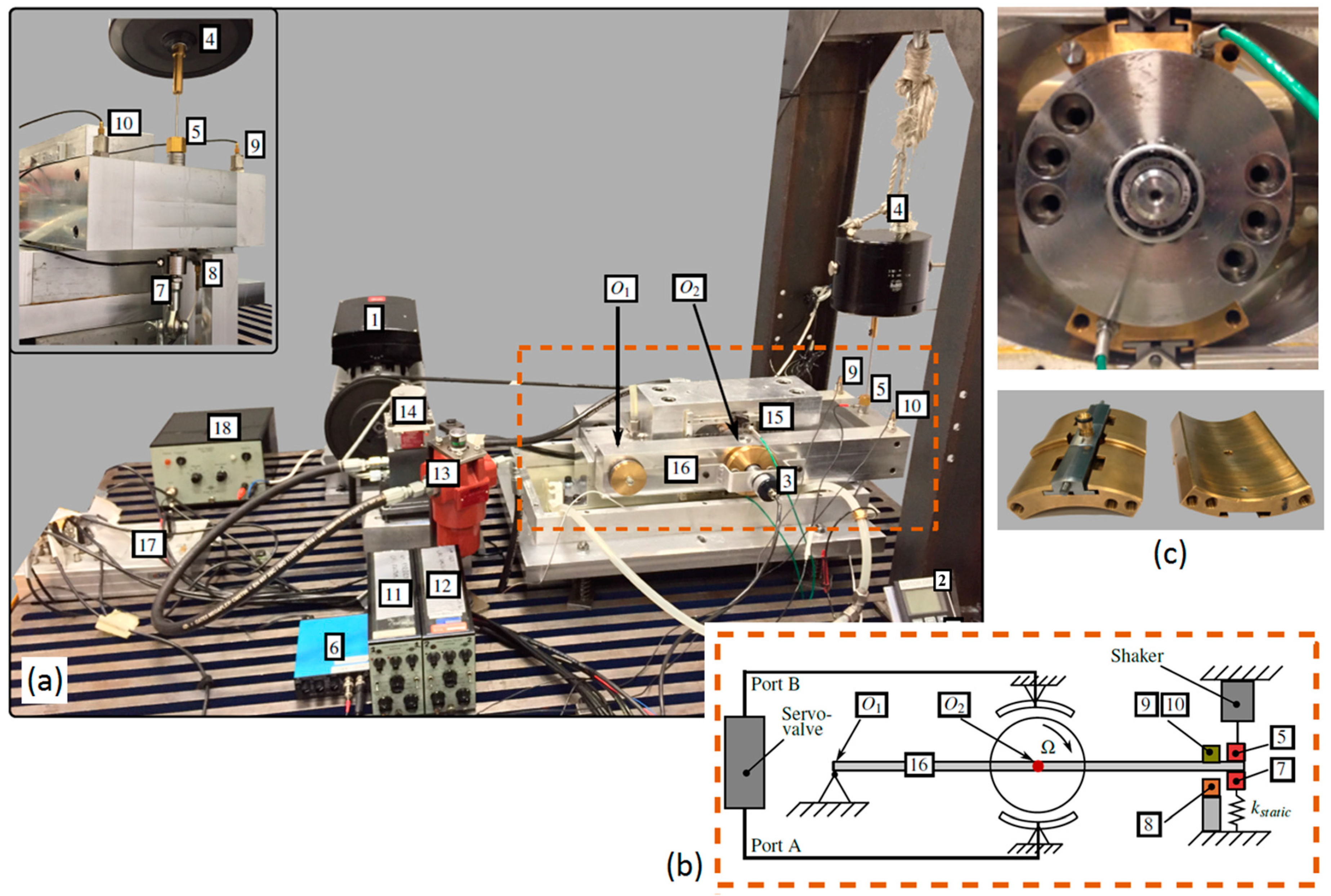
Figure 5 depicts a test bench built to evaluate pairs of industrial tilting-pads under different lubrication regimes using uncompressible fluid (oil), i.e., hydrodynamic, hydrostatic, hybrid, controllable and active. Figure 5a gives an overview of the fully-instrumented bench where all important variables in MRE and Energy equations are electronically monitored by sensors installed on the pads, on the rotor and on the pipelines. The indicated dashed box in red contains the rotor-lever system under investigation, interacting with the pair of tilting-pads. Figure 5b illustrates the operational principle of the test bench. Static and dynamic loads are introduced at the end of the rigid arm, resulting in linear displacement of the rotor center and theoretical and experimental results reported in [44,45,48] demonstrate the usefulness of such a test bench towards validation of multi-physical mathematical models.
6. Industrial Application
The industrial use of controllable and active radial sliding bearings is very modestly reported in the literature [14,15,36]. This claim is based on a thorough literature search and considering the definition of controllable and active lubrication in Section 3. Theoretical examples based on the state-of-the-art models are, however, found for industrial gas compressors [51,52,53], steam turbines [34] as well as reciprocating machines [54,55]. Such theoretical investigations are well documented and based on experimentally-validated computer models. This reinforces the credibility of the theoretical predictions and shows the potentiality of the industrial use.
7. Conclusions and Future Aspects
The evolution of controllable and active sliding bearings over the last three decades leave us no doubt that the technology has clearly developed and is growing in importance and interest, especially considering the framework of Industry 4.0. Nevertheless, the controllable sliding bearings technology is still in its infancy when comparing with the evolution of the active magnetic bearings technology, which took almost a century to find the path to industrial use. As already mentioned, some ideas and patents of controllable sliding bearings have not evolved but others definitely have. Sliding bearings with multi-functionality (based on sensing systems and software) and adaptability (based on several actuator types) are innovative and will be new smart industrial products soon, driven by Industry 4.0.
A challenge to be overcome is to choose, in partnership with interested companies, a few successful and advantageous design solutions/layouts, which are already well-documented, implement them in industrial compressors, turbines, pumps and reciprocating engines, and test them thoroughly, instead of spreading too much energy and resources in additional new design solutions. This claim finds its technical support in the evolution of the active magnetic bearing technology. The mechanical design of active magnetic bearings and their layouts are relatively simple and almost pre-defined, depending on the number of poles. Sliding bearing properties, on the other hands, strongly depend on many parameters as mentioned in Section 2, leaving space for countless design layouts and ways of combining sensing and actuation systems, as shown in Table 1. In order words, some kind of “standardization” or “selection of layouts” of potential controllable and active sliding bearings should be found in close collaboration between academia and industry (manufacturer and users). Such a “standardization” or “selection of layouts” will significantly contribute to faster development and maturity of sliding bearing technology. It is important to highlight hereby that it does not mean that new layouts should not be continuously researched and investigated, but only that some layouts seem more mature than others and they could find their paths to industrial use faster than others, driving the development of the technology.
Conflicts of Interest
The author declares no conflict of interest.
References
- Lee, E.A. Cyber Physical Systems: Design Challenges. In Proceedings of the 11th IEEE International Symposium on Object Oriented Real-Time Distributed Computing (ISORC), Orlando, FL, USA, 5–7 May 2008; pp. 363–369. [Google Scholar]
- Schmidt, R.; Möhring, M.; Härting, R.C.; Reichstein, C.; Neumaier, P.; Jozinović, P. Industry 4.0—Potentials for Creating Smart Products: Empirical Research Results. In Business Information Systems; Lecture Notes in Business Information Processing; Abramowicz, W., Ed.; Springer: Berlin/Heidelberg, Germany, 2015; Volume 208, pp. 16–27. [Google Scholar]
- Brynjolfsson, E.; McAfee, A. The Second Machine Age: Work, Progress, and Prosperity in a Time of Brilliant Technologies; W.W. Norton & Company: New York, NY, USA, 2014. [Google Scholar]
- Brynjolfsson, E.; Hofmann, P.; Jordan, J. Cloud Computing and Electricity: Beyond the Utility Model. Commun. ACM 2010, 53, 32–34. [Google Scholar] [CrossRef]
- Schmidt, R. Industrie 4.0—Revolution oder evolution. Wirtsch. Ostwürtt 2013, 4–7. [Google Scholar]
- Beckert, S. Empire of Cotton: A Global History; Knopf: New York, NY, USA, 2014. [Google Scholar]
- Mühlhäuser, M. Smart Products: An Introduction. In Constructing Ambient Intelligence; Mühlhäuser, M., Ferscha, A., Aitenbichler, E., Eds.; Springer: Berlin/Heidelberg, Germany, 2008; pp. 158–164. [Google Scholar]
- Miche, M.; Schreiber, D.; Hartmann, M. Core Services for Smart Products. In Proceedings of the 3rd European Workshop on Smart Products, Salzburg, Austria, 18–21 November 2009; pp. 1–4. [Google Scholar]
- Santos, I.F. On the Future of Controllable Fluid Film Bearings. Mech. Ind. 2011, 12, 275–281. [Google Scholar] [CrossRef]
- Janocha, H. Neue Aktoren aus Sicht der Mechatronik, Kolloquium Aktoren in Mechatronischen Systemen; Nordmann, R., Isermann, R., Eds.; Fortschritt-Berichte VDI, Reihe 8, Nr. 743; VDI Verlag: Düsseldorf, Germany, 1999; pp. 1–13. [Google Scholar]
- Janocha, H. Adaptronics and Smart Structures—Basics, Materials, Design and Applications; Springer: Berlin, Germany, 1999. [Google Scholar]
- Santos, I.F. Trends in Controllable Oil Film Bearings, Emerging Trends in Rotor Dynamics; IUTAM Bookseries, Volume 1011; Springer: Dordrecht, The Netherlands, 2011; pp. 185–199. [Google Scholar]
- Santos, I.F. Design and evaluation of two types of active tilting pad journal bearings. In The Active Control of Vibration; Mechanical Engineering Publications: London, UK, 1994; pp. 79–87. [Google Scholar]
- Bently, D.E.; Grant, J.W.; Hanifan, P.C. Active Controlled Hydrostatic Bearings for a New Generation of Machines. ASME 2000, V002T03A011. [Google Scholar] [CrossRef]
- Bently, D.E.; Eldridge, T.; Jensen, J.; Mol, P. Externally Pressurized Bearings Allow Rotor Dynamic Optimization. VDI Ber. 2001, 1640, 49–62. [Google Scholar]
- Morosi, S.; Santos, I.F. Active Lubrication Applied to Radial Gas Journal Bearings. Part 1: Modelling. Tribol. Int. 2011, 44, 1949–1958. [Google Scholar] [CrossRef]
- Morosi, S.; Santos, I.F. Experimental Investigations of Active Air Bearings. ASME 2012, 901–910. [Google Scholar] [CrossRef]
- Pierart, F.; Santos, I.F. Steady State Characteristics of an Adjustable Hybrid Gas Bearing—CFD, Modified Reynolds Equation and Experimental Validation. Proc. Inst. Mech. Eng. Part J J. Eng. Tribol. 2015, 229, 807–822. [Google Scholar] [CrossRef]
- Ulbrich, H.; Althaus, J. Actuator Design for Rotor Control. In Proceedings of the 12th Biennial ASME Conference on Vibration and Noise, Montreal, QC, Canada, 17–21 September 1989; pp. 17–21. [Google Scholar]
- Cai, Z.; de Queiroz, M.S.; Khonsari, M.M. On the Active Stabilization of Tilting-Pad Journal Bearings. J. Sound Vib. 2004, 273, 421–428. [Google Scholar] [CrossRef]
- Deckler, D.C.; Veillette, R.J.; Braun, M.J.; Choy, F.K. Simulation and Control of an Active Tilting-Pad Journal Bearing. Tribol. Trans. 2004, 47, 440–458. [Google Scholar] [CrossRef]
- Santos, I.F. Aktive Kippsegmentlagerung—Theorie und Experiment; VDI Fortschritt—Berichte, Reihe 11: Schwingungstechnik, Nr. 189; VDI Verlag: Düsseldorf, Germany, 1993; p. 112. [Google Scholar]
- Krodkiewski, J.M.; Sun, L. Modelling of Multi-Bearing Rotor System Incorporating an Active Journal Bearing. J. Sound Vib. 1998, 210, 215–229. [Google Scholar] [CrossRef]
- Sun, L.; Krodkiewski, J.M.; Cen, Y. Self-Tuning Adaptive Control of Forced Vibration in Rotor Systems Using an Active Journal Bearing. J. Sound Vib. 1998, 213, 1–14. [Google Scholar] [CrossRef]
- Sun, L.; Krodkiewski, J.M. Experimental Investigation of Dynamic Properties of an Active Journal Bearing. J. Sound Vib. 2000, 230, 1103–1117. [Google Scholar] [CrossRef]
- Chasalevri, A.; Dohnal, F. Improving stability and operation of turbine rotors using adjustable journal bearings. Tribol. Int. 2016, 104, 369–382. [Google Scholar] [CrossRef]
- Goodwin, M.J.; Boroomand, T.; Hooke, C.J. Variable Impedance Hydrodynamic Journal Bearings for Controlling Flexible Rotor Vibrations. In Proceedings of the 12th Biennial ASME Conference on Vibration and Noise, Montreal, QC, Canada, 17–21 September 1989; pp. 261–267. [Google Scholar]
- Lin, C.R.; Rylander, H.G., Jr. Performance Characteristics of Compliant Journal Bearings. ASME Trans. J. Tribol. 1991, 113, 639–644. [Google Scholar] [CrossRef]
- Rylander, H.G.; Carlson, M.J.T.; Lin, C.R. Actively-controlled bearing surface profiles—Theory and experiment. In Proceedings of the 1995 American Society of Mechanical Engineers (ASME) Energy Sources Technology Conference and Exhibition, Houston, TX, USA, 29 January–1 February 1995; pp. 11–14. [Google Scholar]
- Osman, T.A.; Nada, G.S.; Safar, Z.S. Static and Dynamic Characteristics of Magnetised Journal Bearings Lubricated with Ferrofluid. Tribol. Int. 2001, 34, 369–380. [Google Scholar] [CrossRef]
- Laukiavich, C.A.; Braun, M.J.; Chandy, A.J. A comparison between the performanceof ferro- and magnetorheological fluids in a hydrodynamic bearing. Proc. Inst. Mech. Eng. Part J J. Eng. Tribol. 2014, 228, 649–666. [Google Scholar] [CrossRef]
- Andrew, D.D.; Alexander, K. Electrorheological Fluid-Controlled “Smart” Journal Bearings. Tribol. Trans. 1992, 35, 611–618. [Google Scholar]
- Fürst, S.; Ulbrich, H. An Active Support System for Rotors with Oil-Film Bearings. In Proceedings of the 4th International Conference on Vibrations in Rotating Machinery of the Institution of Mechanical Engineers, Heriot-Watt University, Edinburgh, UK, 13–15 September 1988; pp. 61–68. [Google Scholar]
- San Andres, L.; Childs, D. Angled injection-hydrostatic bearings analysis and comparison to test results. ASME J. Tribol. 1997, 119, 179–187. [Google Scholar] [CrossRef]
- Santos, I.F.; Watanabe, F.Y. Compensation of Cross-Coupling Stiffness and Increase of Direct Damping in Multirecess Journal Bearings Using Active Hybrid Lubrication: Part I—Theory. ASME J. Tribol. 2004, 126, 146–155. [Google Scholar] [CrossRef]
- Martin, J.K.; Parkins, D.W. Testing of a Large Adjustable Hydrodynamic Journal Bearing. Tribol. Trans. 2001, 44, 559–566. [Google Scholar] [CrossRef]
- Agrawal, A.; Ciocanel, C.; Martinez, T.; Duggan, J. A Bearing Application Using Magnetorheological Fluid. J. Intell. Mater. Syst. Struct. 2002, 13, 667–673. [Google Scholar] [CrossRef]
- Haugaard, M.A.; Santos, I.F. Elastohydrodynamics Applied to Active Tilting-Pad Journal Bearings. ASME J. Tribol. 2010, 132. [Google Scholar] [CrossRef]
- Pierart, F.G.; Santos, I.F. Active lubrication applied to radial gas journal bearings. Part 2: Modelling improvement and experimental validation. Tribol. Int. 2016, 96, 237–246. [Google Scholar] [CrossRef] [Green Version]
- Pierart, F.G.; Santos, I.F. Lateral vibration control of a flexible overcritical rotor via an active gas bearing—Theoretical and experimental comparisons. J. Sound Vib. 2016, 383, 20–34. [Google Scholar] [CrossRef]
- Pierart, F.G.; Santos, I.F. Adjustable hybrid gas bearing—Influence of piezoelectrically adjusted injection on damping factors and natural frequencies of a flexible rotor operating under critical speeds. Proc. Inst. Mech. Eng. Part J J. Eng. Tribol. 2016, 230, 1209–1220. [Google Scholar] [CrossRef]
- Theisen, L.R.; Niemann, H.H.; Santos, I.F.; Galeazzi, R.; Blanke, M. Modelling and Identification for Control of Gas Bearings. Mech. Syst. Signal Process. 2016, 70–71, 1150–1170. [Google Scholar] [CrossRef] [Green Version]
- Salazar, J.G.; Santos, I.F. Active tilting-pad journal bearings supporting flexible rotors: Part II—The model-based feedback-controlled lubrication. Tribol. Int. 2017, 107, 106–115. [Google Scholar] [CrossRef]
- Varela, A.C.; Fillon, M.; Santos, I.F. On the simplifications for the thermal modeling of tilting-pad journal bearings under thermoelastohydrodynamic regime. ASME 2012, 823–835. [Google Scholar] [CrossRef]
- Varela, A.C.; Nielsen, B.B.; Santos, I.F. Steady state characteristics of a tilting pad journal bearing with controllable lubrication: Comparison between theoretical and experimental results. Tribol. Int. 2013, 58, 85–97. [Google Scholar] [CrossRef]
- Salazar, J.G.; Santos, I.F. Active tilting-pad journal bearings supporting flexible rotors: Part I—The hybrid lubrication. Tribol. Int. 2017, 107, 94–105. [Google Scholar] [CrossRef]
- Santos, I.F.; Varela, A.C. Actively lubricated bearings applied as calibrated shakers to aid parameter identification in rotordynamics. ASME 2013, V07BT30A025. [Google Scholar] [CrossRef]
- Santos, I.F.; Svendsen, P.K. Noninvasive Parameter Identification in Rotordynamics via Fluid Film Bearings—Linking Active Lubrication and Operational Modal Analysis. J. Eng. Gas Turbines Power 2017, 139. [Google Scholar] [CrossRef]
- Simonsen, M.K. Experimental Modal Analysis applied to Flexible Rotors Supported by Oil Lubricated Bearings. Master’s Thesis, DTU Mechanical Engineering Department, Kongens Lyngby, Denmark, 2016. [Google Scholar]
- Cerda, A.; Santos, I.F. Validity of the modified Reynolds equation for incompressible active lubrication. Proc. Inst. Mech. Eng. Part J J. Eng. Tribol. 2016, 230, 1490–1502. [Google Scholar] [CrossRef]
- Santos, I.F.; Nicoletti, R.; Scalabrin, A. Feasibility of Applying Active Lubrication to Reduce Vibration in Industrial Compressors. ASME J. Eng. Gas Turbines Power 2004, 126, 888–894. [Google Scholar] [CrossRef]
- Varela, A.C.; Santos, I.F. Stability Analysis of an Industrial Gas Compressor Supported by Tilting-Pad Bearings under Different Lubrication Regimes. ASME J. Eng. Gas Turbines Power 2012, 134. [Google Scholar] [CrossRef]
- Varela, A.C.; Santos, I.F. Performance Improvement of Tilting-Pad Journal Bearings by Means of Controllable Lubrication. Mech. Ind. 2012, 13, 17–32. [Google Scholar] [CrossRef]
- Estupinan, E.; Santos, I.F. Controllable lubrication for main engine bearings using mechanical and piezoelectric actuators. IEEE/ASME Trans. Mech. 2012, 17, 279–287. [Google Scholar] [CrossRef]
- Estupinan, E.; Santos, I.F. Radial oil injection applied to main engine bearings: Evaluation of injection control rules. J. Vib. Control 2012, 18, 587–595. [Google Scholar] [CrossRef]
Figure 1.
Design details and test bench of controllable radial sliding bearing: (a) the test rig composed of a flexible rotor supported by an actively air lubricated radial bearing, where eddy-current sensors provide information about the rotor lateral vibrations; (b) the piezoelectrically-controlled air lubrication; (c) the piezoelectric actuator; (d) the piezoelectrically-controlled air injection.

Figure 2.
Theoretical and experimental frequency response of the rotating disc due to impulse excitations where the hybrid lubrication is illustrated in gray and the active lubrication in black: (a) theoretical results and (b) experimental results [39].
Figure 2.
Theoretical and experimental frequency response of the rotating disc due to impulse excitations where the hybrid lubrication is illustrated in gray and the active lubrication in black: (a) theoretical results and (b) experimental results [39].
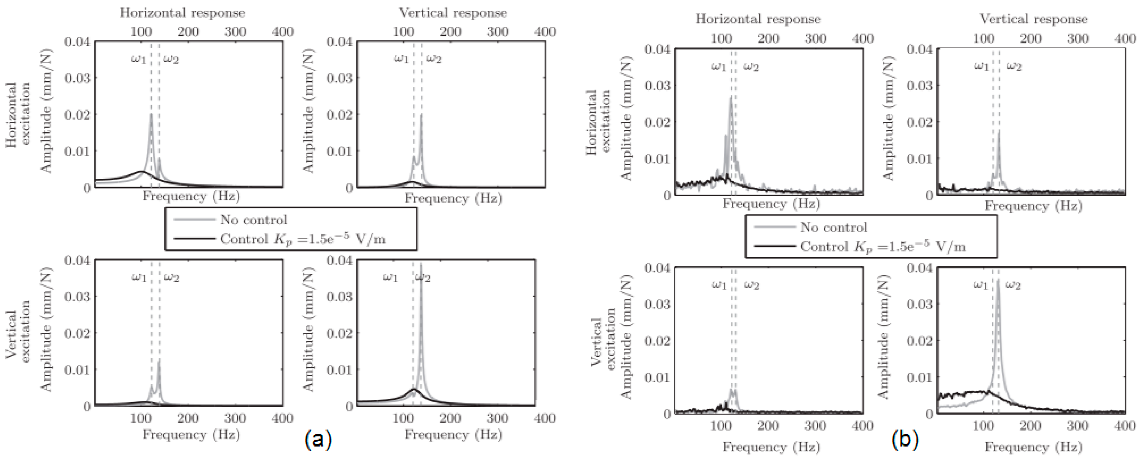
Figure 3.
(a) Sliding bearing with incorporated sensing and actuation systems; (b) design solution and compactness; (c) test bench composed of a flexible rotor-disc excited by an electromagnetic shaker and controlled via active sliding bearing.
Figure 3.
(a) Sliding bearing with incorporated sensing and actuation systems; (b) design solution and compactness; (c) test bench composed of a flexible rotor-disc excited by an electromagnetic shaker and controlled via active sliding bearing.
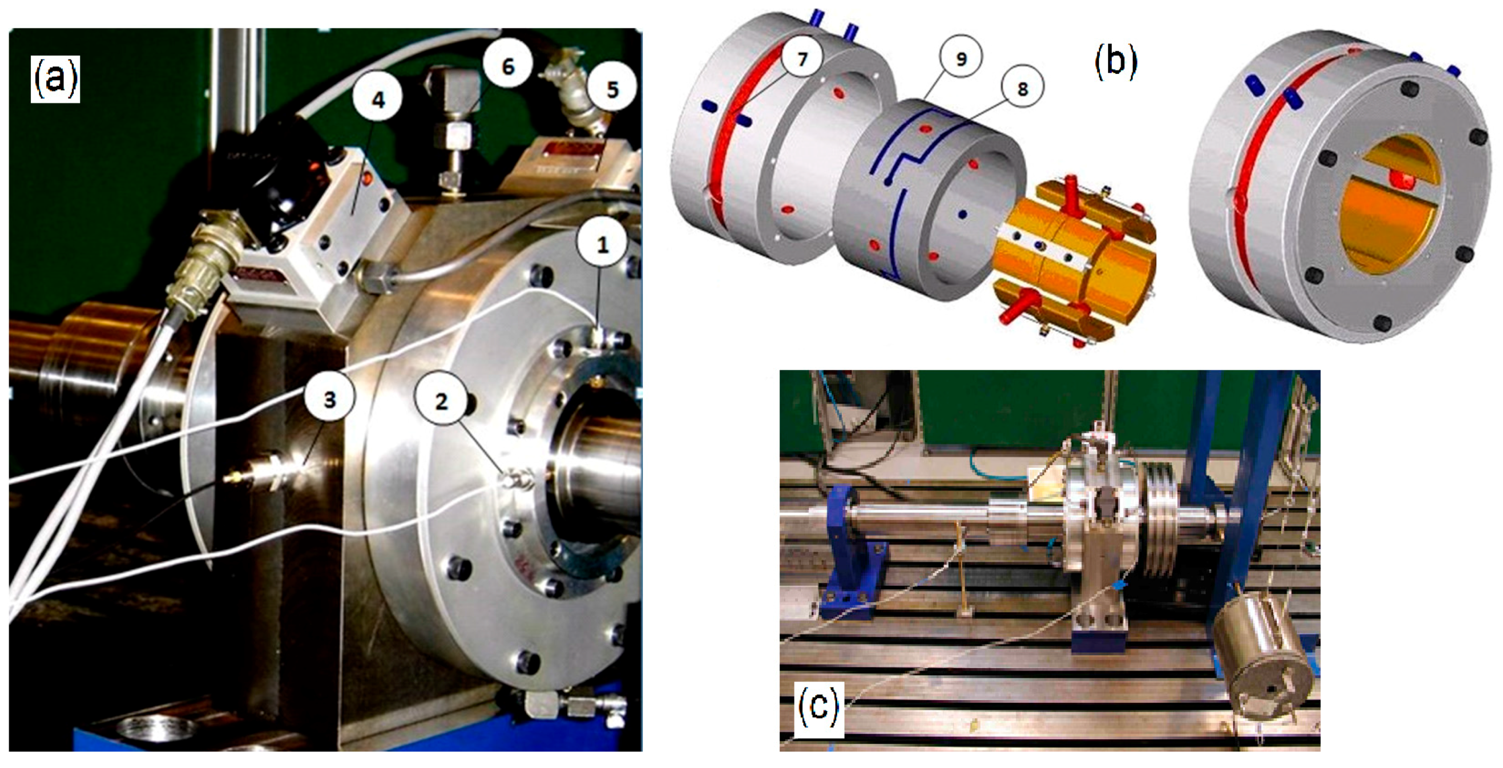
Figure 4.
Horizontal and vertical lateral dynamics of the rotor–bearing system measured at the end of the shaft and excited by the electromagnetic shaker when four cases are investigated: hydrodynamic (conventional); hybrid using 100 bar; active using a LQG model-based controller; and active using an empirically-tuned PID controller [43]. Copyright from Elsevier.
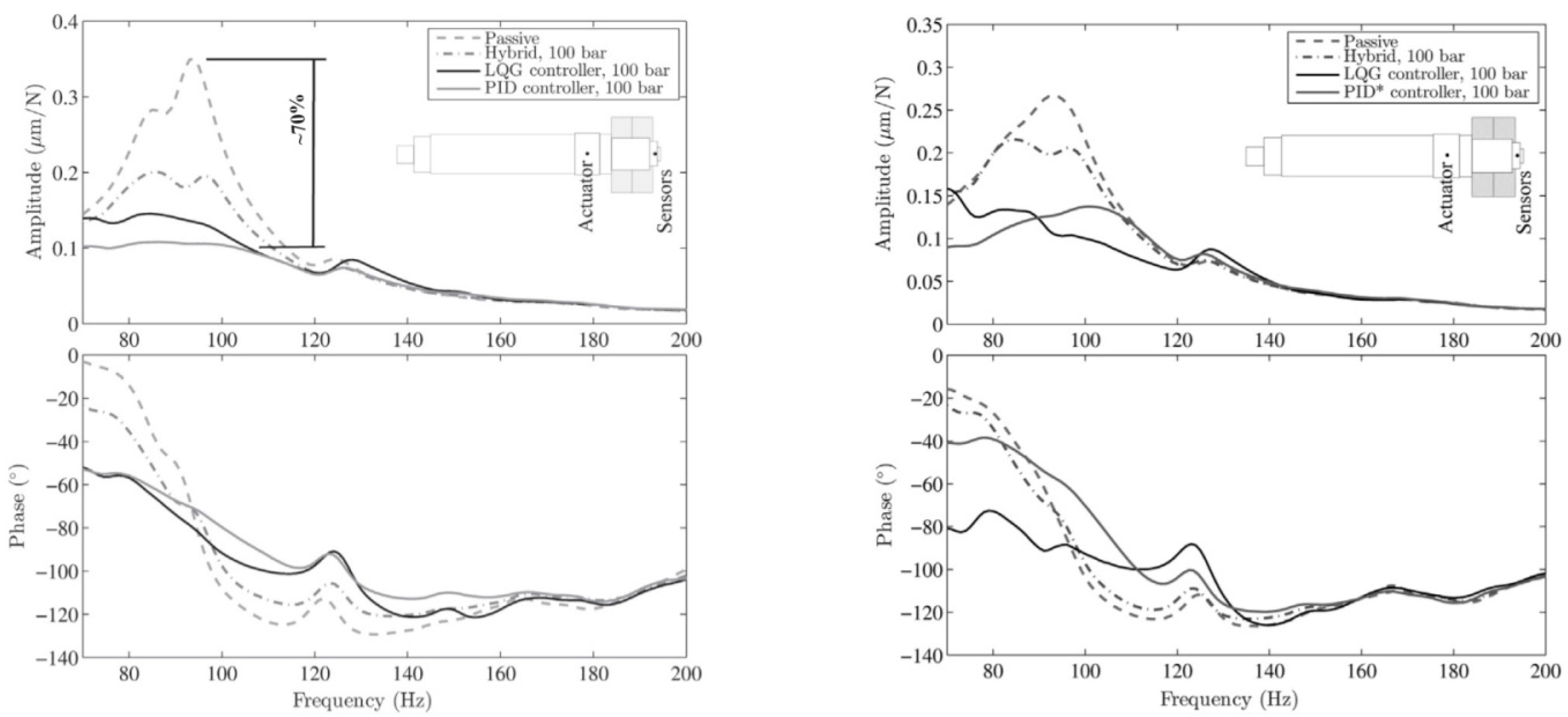
Figure 5.
(a) Photo of the test bench with instrumentation: 1 AC motor and frequency converter; 2 Control unit for the frequency converter; 3 Tachometer; 4 Electromagnetic shaker; 5 Force transducer; 6 Amplifier for the force transducer; 7 Force transducer for the static load; 8 Displacement sensor; 9 and 10 Accelerometers; 11 and 12 Amplifiers for the accelerometers; 13 Oil filter; 14 Servovalve; 15 Pressure sensor (green wire); 16 Frame; 17 dSpace unit for signal acquisition; 18 Amplifier for the electromagnetic shaker; (b) dashed box containing the schematized rotor-lever system; (c) pair of instrumented tilting-pads dismounted and mounted on the rotor.


Table 1.
Overview of some innovative strategies for rendering adaptability and multi-functionality to radial sliding bearings.
Table 1.
Overview of some innovative strategies for rendering adaptability and multi-functionality to radial sliding bearings.
| Sliding Bearing Type | Control Variable | Actuator Type | Authors | Year |
|---|---|---|---|---|
| adjustable multi-recessed bearing | pressure | hydraulic accumulator | Goodwin [27] | 1989 |
| active housing of a circular-bearing | housing motion | electromagnetic | Ulbrich, Fürst [33] | 1988 |
| active tilting-pads | bearing gap | piezoelectric stacks | Ulbrich, Althaus [19] | 1989 |
| Deckler, Veillette, Braun, Choy [21] | 2000 | |||
| circular | viscosity | electrorheological | Andrew, Alexander [32] | 1992 |
| active tilting-pads | bearing gap | hydraulic chamber system | Santos [22] | 1993 |
| actively-lubricated tilting-pads (orifices) | pressure, flow | hydraulic (servovalves) | Santos [13] | 1994 |
| circular | gap, deformable bushing | hydraulic (servovalves) | Rylander, Carlson, Lin [29] | 1995 |
| hydrostatic bearings | Angled flow injection | mechanical/manual | San Andres, Childs [34] | 1997 |
| controllable segmented bushing | gap gradient | hydraulic | Krodkiewski, Sun [23] | 1998 |
| adjustable multi-recess bearing | pressure, flow | hydraulic (servovalves) | Bently [14] | 2000 |
| active multi-recess bearing | pressure, flow | hydraulic (servovalves) | Santos, Watanabe [35] | 2000 |
| partial arc (three pads) | gap, gap slope | mechanical/manual | Martin, Parkins [36] | 2001 |
| circular | viscosity | magneto-rheological | Agrawal, Ciocanel, Martinez, Duggan [37] | 2002 |
| Laukiavich, Braun, Chandy [31] | 2014 | |||
| deformable actively-lubricated tilting-pads (orifices) | pressure, flow, gap | hydraulic (servovalves) | Santos, Haugaard [38] | 2010 |
| partial arc bearing (two pads) | gap, preload | mechanical/manual | Chasalevris, Dohnal [26] | 2014 |
© 2018 by the author. Licensee MDPI, Basel, Switzerland. This article is an open access article distributed under the terms and conditions of the Creative Commons Attribution (CC BY) license (http://creativecommons.org/licenses/by/4.0/).
Share and Cite
MDPI and ACS Style
Santos, I.F. Controllable Sliding Bearings and Controllable Lubrication Principles—An Overview. Lubricants 2018, 6, 16. https://doi.org/10.3390/lubricants6010016
AMA Style
Santos IF. Controllable Sliding Bearings and Controllable Lubrication Principles—An Overview. Lubricants. 2018; 6(1):16. https://doi.org/10.3390/lubricants6010016
Chicago/Turabian StyleSantos, Ilmar F. 2018. "Controllable Sliding Bearings and Controllable Lubrication Principles—An Overview" Lubricants 6, no. 1: 16. https://doi.org/10.3390/lubricants6010016
Note that from the first issue of 2016, this journal uses article numbers instead of page numbers. See further details here.