TEHL Simulation on the Influence of Lubricants on the Frictional Losses of DLC Coated Gears †


Gear Research Centre (FZG), Technical University of Munich, Boltzmannstraße 15, 85748 Garching b. München, Germany
*
Author to whom correspondence should be addressed.
†
This paper is an extended version of an abstract published in World Tribology Congress 2017, Beijing, China, 17–22 September 2017.
Lubricants 2018, 6(1), 17; https://doi.org/10.3390/lubricants6010017
Submission received: 6 December 2017
/
Revised: 17 January 2018
/
Accepted: 31 January 2018
/
Published: 10 February 2018
(This article belongs to the Special Issue Selected Papers in the Sixth World Tribology Congress (WTC 2017))
Abstract
:Diamond-Like Carbon (DLC) coatings can reduce fluid friction in TEHL contacts (thermo-elastohydrodynamic lubrication) of meshing gears. This study investigates the influence of different base oils i.e., mineral, polyalphaolefin and polyglycol oil on the friction of DLC coated spur gears. Thereby, a transient TEHL simulation model based on the finite element based full-system approach coupled iteratively with the thermal equations is applied, considering mechanical and thermal properties of the DLC coatings. Results show a clear reduction of fluid friction in DLC coated gears for all considered lubricants. This can be traced back to higher TEHL temperatures for DLC coated gears, which is due to its low thermal inertia resulting in a thermal insulation effect.
1. Introduction
The increasing performance and efficiency requirements of drive systems are stimulating the further development of geared transmissions. Their power losses can be divided into no-load and load-dependent power losses. Whereas the no-load power loss is mainly caused by the circulation of lubricant [1], the load-dependent power loss of gears is determined by sliding velocity, normal force and the coefficient of friction along the path of contact [2,3]. Recent experimental and theoretical investigations have shown that Diamond-Like Carbon (DLC) coatings can quite significantly reduce friction in TEHL contacts (thermo-elastohydrodynamic lubrication). DLC coatings can be classified in hydrogenated amorphous carbon (a-C:H) and tetrahedral amorphous carbon (ta-C) coatings, which can be doped by metals or non-metallic elements [4]. Commonly proposed explanation of the friction reduction by DLC coatings in fluid lubrication regime are wall slip related to the wetting behavior and thermal insulation effects related to the coatings’ thermal properties.
Evans et al. [5] investigated the influence of different DLC coatings using a ball-on-disk tribometer. Amorphous hydrocarbon (WC/a-C:H) and silicon doped DLC (Si-DLC) coated specimens showed lower friction by up to 20% compared to chromium nitride (CrxN) coated and uncoated specimens. A decrease in friction with increasing hydrocarbon content of the WC/a-C:H and Si-DLC coatings was observed at high specific film thickness. The authors address wall slip between dispersive lubricants and the highly dispersive coated surface as causal factor for the friction reduction. Wall slip was further investigated by Kalin et al. [6,7,8] by focusing on the poor wetting behavior of lubricants with DLC coatings compared to steel surfaces. A maximum friction reduction of about 20% was found in a ball-on-flat reciprocating test rig [8]. The spreading parameter, which correlates well with the surface energy, is proposed to describe the wetting behavior of surfaces [6,7]. Björling et al. [9] investigated the effect of both wall slip and thermal insulation on the friction reduction with a-C:H coated specimens in a ball-on-disk tribometer. The results showed decreasing friction with increasing coating thickness. Measured contact angles and surface energies as well as spreading parameters could not be holistically correlated to the observed friction reductions by up to 41%. The authors conclude that mainly thermal effects are responsible for the friction reduction of the considered DLC coatings.
Elsharkawy et al. [10] performed simulations on the influence of surface coatings on the TEHL contact. Thereby, the mechanical properties of the coatings and their thickness showed a considerable influence on pressure and film thickness distribution. The results showed wider contact areas and lower maximum pressure for coatings with low elastic modulus, due to higher surface deformation, and reduced transient pressure distribution for rough surfaces. The influence of the mechanical properties of the surface coatings is reduced with decreasing coating thickness. Björling et al. [11,12] used a combined experimental and simulation approach to investigate the friction reduction by DLC coatings. Experimental investigations were performed on a ball-on-disk tribometer using a mineral oil and different a-C:Cr and hydrogenated amorphous carbon ((Cr+)a-C:H) coated and uncoated disks and balls. A clear friction reduction by up to 16% was found when a coating is applied to the disk or the ball. The largest friction reduction by up to 25% was observed for coated disk and coated ball. The simulation results showed the largest TEHL temperatures when both surfaces were coated and the lowest when both surfaces were uncoated. Thereby, significant changes in temperature and velocity profiles in the TEHL contact were shown for coated contacts. The authors proposed thermal effects due to thermal insulation of the considered DLC coatings to be responsible for the friction reduction. Habchi [13] used a finite element based TEHL simulation model to investigate the influence of the mechanical and thermal properties of coatings on the TEHL contact. The results on the influence of the mechanical properties and the coatings’ thickness are generally in accordance with the results of Elsharkawy et al. [10]. The results on coatings with low thermal inertia showed a pronounced decrease in friction by up to 50%, which is attributed to the significant increase in TEHL temperature due to thermal insulation. A high coating thickness and high sliding enhanced these effects. Results on coatings with a high thermal inertia showed temperatures and coefficients of friction comparable to uncoated specimens. Based on TEHL simulations Habchi and Bair [14] showed a friction reduction for mechanically soft coatings with low thermal inertia compared to uncoated surfaces in the linear friction and the thermoviscous friction regime. This can be traced back to piezoviscous behavior of the lubricant in the linear friction regime and to both piezoviscous and thermoviscous behavior in the thermoviscous friction regime. The authors note that friction in EHL contacts is complex and involves so many different physics and mechanisms that general conclusions are difficult. Bobach et al. [15] showed the friction reduction of DLC coated surfaces by means of experiments at a FZG twin-disk test rig and TEHL simulations. The DLC coating includes a-C:H layer at the surface and a WC and Cr layer as undercoating. Experimental and simulation results showed friction reductions by up to 40% and higher TEHL contact temperatures for coated disks. Also, a lower stationary bulk temperature was measured due to thermal insulation of the TEHL contact. The low heat conductivity of the considered DLC coating is identified as the cause for the increase of TEHL temperatures and hence for the friction reduction. Bobzin et al. [16] investigated the influence of metal (Cr and Zr) and hydrogen containing carbon based coatings on the frictional behavior of disks and spur gears using a FZG twin-disk and a FZG gear efficiency test rig. The DLC coated specimens showed lower friction by up to 35% for the considered mineral oil in the mixed and fluid lubrication regime than the uncoated specimens, especially for operating conditions with high sliding. The friction reduction is referred to the low thermal inertia of DLC coatings and the consequential thermal insulation effect leading to lower lubricant viscosity in the TEHL contact. Lohner et al. [17] compared TEHL contact temperature measurements by thin film sensors in a FZG twin-disk test rig with TEHL simulation results and showed higher contact temperatures for SiO2 and Al2O3 coated compared to uncoated surfaces. Beilicke et al. [18] performed TEHL simulations on the transient TEHL contact of a DLC coated helical gear pair considering mixed lubrication. The considered DLC coating was adopted from Bobach et al. [15]. The results show higher TEHL temperatures, lower coefficients of friction and minimum film thickness values along the path of contact when both, pinion and wheel, are coated compared to when just one gear or no gear is coated. For the single-sided coated gear pair, the lubricant temperature in the TEHL contact was shifted towards the coated surface due to the poor thermal conductivity of the DLC coating. Beilicke et al. [18] conclude that the friction reduction by up to 27% is caused by thermal insulation of the considered DLC coatings leading to lower effective viscosity in the TEHL contact.
The literature shows that many studies attribute the friction reduction of DLC coatings to their low thermal inertia and the consequential thermal insulation effect on the TEHL contact. This is also the main focus of this study. Other suggested effects as wall slip [6,7] are not discussed. As the influence of lubricants with different rheological properties on the friction reduction of DLC coatings has hardly been considered so far, this study investigates the influence of different base oils on the friction of DLC coated spur gears using a TEHL simulation model based on Lohner et al. [19] and continues the work of Ziegltrum et al. [20]. The results of this study were partly presented at a technical session at the 6th World Tribology Congress in Beijing in 2017 [21].
2. TEHL Simulation
The transient TEHL contact of DLC coated spur gears is analyzed using the TEHL simulation model described by Lohner et al. [19] and Ziegltrum et al. [20]. Only the main physical and numerical characteristics are described below. The employed explanations and formulations are based on [19,20].
2.1. Generalized Reynolds Equation
The generalized Reynolds equation for non-Newtonian fluid behavior, varying density and viscosity according to Yang and Wen [22] describes the hydrodynamics in the TEHL contact:
2.2. Contact Mechanics
The elastic deformation of the considered equivalent body in gap height direction is calculated by the finite element method, neglecting any dynamic response of the solids (Raisin et al. [25]):
Zero displacement at the bottom of the equivalent body and zero normal and tangential stress on the sides of the equivalent body are used as boundary conditions. The coatings are considered by an additional computational domain in the upper part of the equivalent body as suggested by Habchi [13]. Thereby, the equivalent Poisson’s ratio and the Young’s modulus as the mechanical properties of the equivalent body are defined separately for the substrate and the coating in two subdomains [13,26].
The lubricant film thickness is described by the film thickness equation:
The constant parameter results from the load balance equation, is the undeformed geometry and the elastic deformation in gap height direction. In this study, deviation from the smooth profile is zero.
The load balance equation is written as balance of the integrated hydrodynamic pressure and the applied load:
2.3. Energy Conservation
The temperature distribution in the lubricant is described by its transient energy equation including sources due to shearing and compression of the lubricant:
The transition between substrates, coatings and lubricant is realized by temperature and conductive heat flux continuity conditions. The transient energy equation for the substrate (s) and coating (c) for the solid bodies (1,2) can be written as:
As boundary conditions, substrate, coating and lubricant entering the calculation domain are set to bulk temperature . For the substrate, coating and lubricant leaving the calculation domain, zero conductive heat flux is assumed. The height of the calculation domain is chosen to be sufficiently large so that the conductive heat flux into the substrates becomes zero [13]. Hence, the bulk temperature is set at the upper and lower boundaries of the substrates.
2.4. Lubricant Properties
The temperature and pressure dependency of the viscosity is defined as suggested by Hepermann et al. [27]. The temperature dependency at ambient pressure is described according to Vogel [28], Fulcher [29] and Tammann and Hesse [30]:
The pressure dependency of the viscosity at a given temperature is modelled according to Roelands equation [31]:
with a temperature-dependent pressure exponent given by
and a temperature-dependent pressure viscosity coefficient given by
The non-Newtonian fluid behavior is described by the simplified Bair/Winer model (Wolff and Kubo [32]), neglecting visco-elastic effects:
The limiting shear stress is derived from measured friction curves at the twin-disk test rig and adjusted for usage in TEHL simulations [33]. This limiting shear stress depends on the local TEHL pressure and temperature, the entrainment velocity and the type of lubricant. Its minimal value is set to .
The temperature and pressure dependency of the lubricant density is modelled with the Bode model [34]:
The temperature and pressure dependency of the lubricant thermal conductivity and the specific heat capacity per volume are based on the models of Larsson and Andersson [35]. In these models, different parameters are available for different lubricant types.
2.5. Numerical Procedure
The numerical procedure of the TEHL simulation model is based on a complete FE formulation that follows the full-system approach, which is coupled iteratively with thermal equations (Habchi et al. [26]). Its application to the transient TEHL contact of spur gears was shown by Ziegltrum et al. [20] and implemented in the commercial software COMSOL Multiphysics [36]. The coatings are considered by additional computational domains for the deformation and temperature calculation as suggested by Habchi [13]. For pressure and film thickness calculation in the FEM-model , a free triangular mesh with a refinement at the substrate-coating interface by a distribution with about elements is used. The coating domain on top of the substrate domain features an equidistant mesh with about elements in gap height direction. For the temperature calculation in the FEM-model , the lubricant and the coating domains feature an equidistant mesh with elements in gap length direction and about elements for the lubricant and each coating domain in gap height direction. The solid calculation domains in the FEM-model are meshed with a refinement on the substrate-coating boundaries. For more details, the reader is referred to Ziegltrum et al. [20] and Lohner et al. [19].
3. Results and Discussion
In this section, the results of the TEHL simulations on the influence of the lubricant type on the frictional losses and the related quantities along the path of contact of DLC coated gears are presented.
The object of investigation is the FZG gear efficiency test rig with FZG type Cmod gears [37]. As the focus of this study is the fluid film lubrication regime, smooth surfaces are assumed. Table 1 shows the most important gear parameters of the cylindrical spur gear FZG type Cmod.
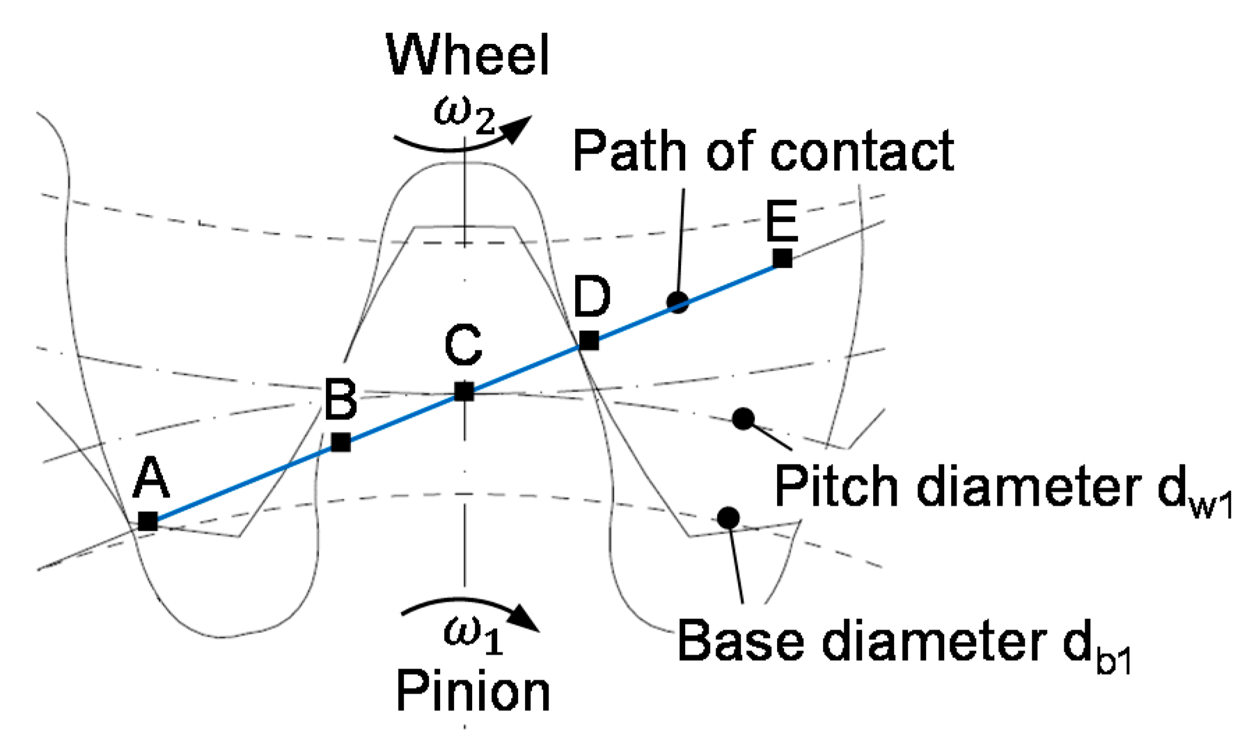
Figure 1 shows a geometry plot of the considered FZG type Cmod gear. The plot is derived from the FVA program STplus (Fromberger et al. [38]).
Table 2 shows the properties of the considered steel substrate material (16MnCr5E) and DLC coatings. The properties of the DLC(I↓) coating were measured by Bobzin et al. [39]. This hydrogenated amorphous carbon-based coating is doped with Zirconium. The thermal properties of the hydrogenated amorphous carbon DLC(I↓↓) coating are adopted from the measurements of Becker et al. [40]. Note that the considered thermal properties measured in the as-manufactured state are assumed to be representative of the conditions under tribological load. As for the DLC(I↓↓) coating, the mechanical properties are unknown, the properties of the substrate are assumed. Due to the very small thickness of the coatings, this assumption is very reasonable [13].
Note that the DLC(I↓) coating features a thermal inertia that is two times lower than the substrate material 16MnCr5E and the DLC(I↓↓) coating a thermal inertia that is eight times lower. The thermal inertia is defined as and represents the ability to transport heat by conduction and advection, respectively [13]. The thermal inertia of the coatings describes the ability to transport heat from the TEHL contact into the substrate material. Hence, the considered DLC coatings act as a thermal insulator. A coating thickness of is considered for both pinion and wheel. No further undercoatings are considered, as they are already included in the properties from [39,40].
The choice of the considered lubricants is based on experimental results from the FZG gear efficiency test rig of Hinterstoißer [37], who observed very different mean gear coefficients of friction when comparing mineral, polyalphaolefin and polyglycol oils. Table 3 shows the main properties and model parameters of the considered mineral oil (MIN100), polyalphaolefin oil (PAO100) and polyglycol oil (PG100). The parameters of Equations (7)–(10) and (12) are obtained by regression analysis. The underlying measurements (ITR Clausthal [41]) of the lubricant viscosity and density correspond to four temperatures and pressures of up to . A complete list of the lubricant parameters can be found in Ziegltrum et al. [20].
Table 4 shows the considered operating condition. For comparison and interpretation, the bulk temperature is kept constant at in this study. Note that in practical systems, different lubricants and coatings result in different bulk temperatures of the gears for a constant operating condition.
For the operating condition in Table 4, Figure 2 shows the derived line load , Hertzian pressure , radius of curvature , sum velocity , sliding velocity , slip ratio and slide-to-roll ratio along the path of contact for the FZG-type Cmod gear. The data is derived from the FVA program RIKOR (Stiller et al. [42]), which includes the elastic deflection of shafts, bearings and gear teeth. The load distribution is averaged along the face width. The sum velocity and the sliding velocity are defined by the velocity of the pinion and the velocity of the wheel :
The slip ratio and the slide-to-roll ratio are defined as:
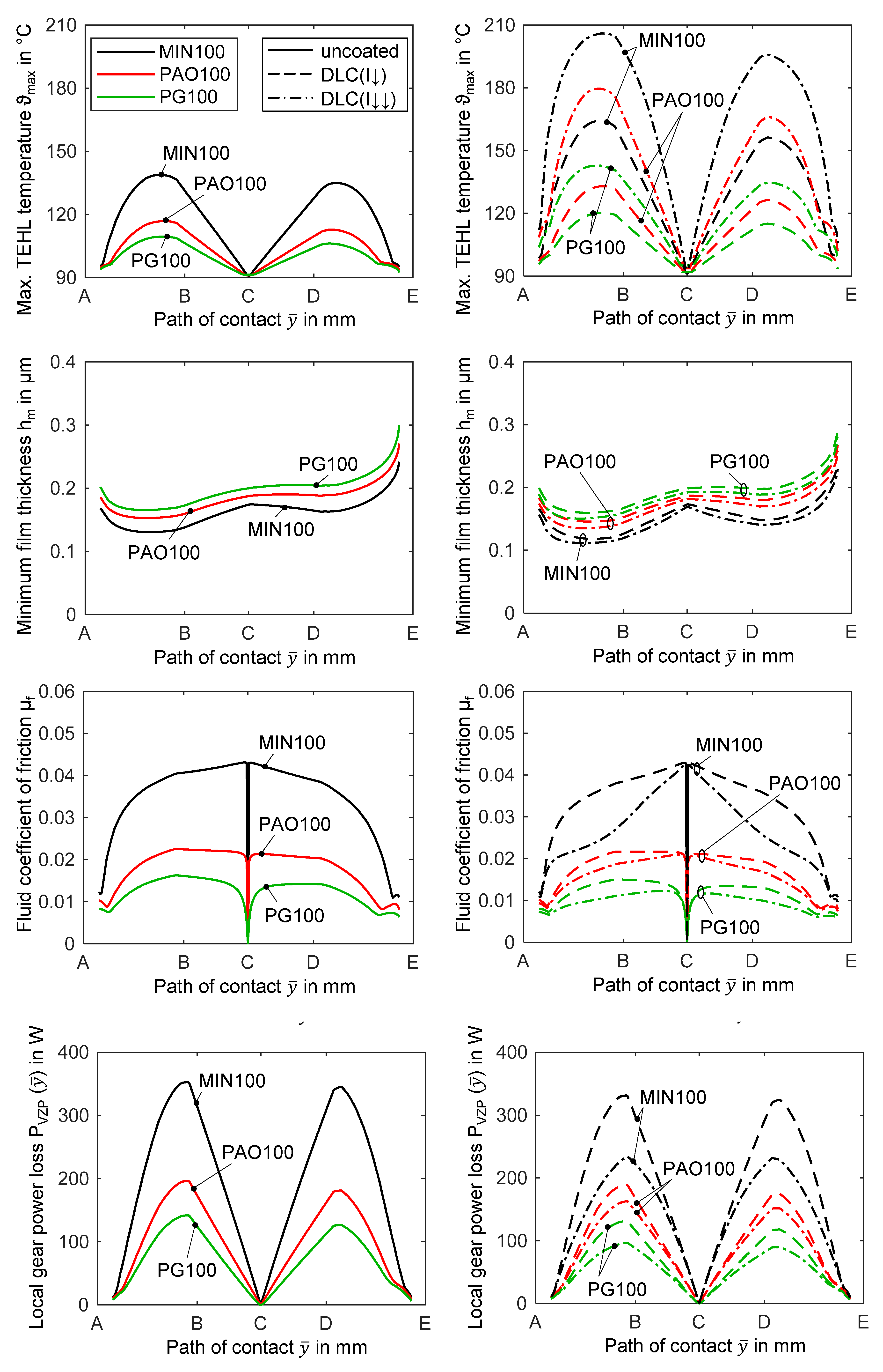
In general, the mechanical and thermal properties of the surface coatings influence the deformation and temperature in the TEHL contact. The mechanical properties of the considered DLC coatings and their effect on the deformation and TEHL quantities are negligible due to the coatings’ very small thickness of (see also Habchi [13]). Hence, the presentation of the results focuses on the influence of the thermal properties of the DLC coatings. Figure 3 shows the maximum TEHL temperature , the minimum film thickness , the fluid coefficient of friction and the local gear power loss along the path of contact for uncoated (left) and DLC(I↓) and DLC(I↓↓) coated gears (right) in comparison with MIN100, PAO100 and PG100.
3.1. TEHL Temperature along the Path of Contact
The maximum TEHL temperature generally shows a similar trend for the considered lubricants and coatings. After an increase at the beginning of contact (A) as it approaches the beginning of singular contact (B), decreases to almost bulk temperature as it approaches the pitch point (C). After C, increases again as it approaches the end of singular contact (D) and decreases as it approaches the end of contact (E). The general trend of at A and E is strongly determined by the line load as it approaches zero. Around B and D, high values of and result in high . At C, almost no temperature increase is present due to the pure rolling condition (). Comparing the lubricant types, MIN100 shows a higher than PAO100 and itself shows a higher than PG100. The differences between the lubricants for uncoated, DLC(I↓) and DLC(I↓↓) coated gears can be traced back to the different fluid coefficients of friction µf discussed in Section 3.3.
For each lubricant, the maximum TEHL temperature of coated gears is higher than for uncoated gears due to thermal insulation. The increase of is more pronounced for the DLC(I↓↓) coating than for the DLC(I↓) coating due to the thermal inertia of DLC(I↓↓) that is four times lower than DLC(I↓). For the DLC(I↓) coating, the maximum relative temperature rise referred to uncoated gears is for MIN100, for PAO100 and for PG100. For the DLC(I↓↓) coating, the strongest relative temperature rise expressed as is observed, with a maximum of for MIN100, for PAO100 and for PG100. Note that the maximum value of of for the DLC(I↓↓) coating and MIN100 corresponds, expressed on the Celsius scale, to an approximately -fold bulk temperature. At C, is comparable for uncoated and coated gears due to the pure rolling condition. The general results on the TEHL temperature in the comparison between uncoated and coated contacts are in accordance with the results of Beilicke et al. [18] and Habchi [13]. The higher TEHL temperatures can influence the thermal degradation of the lubricants.
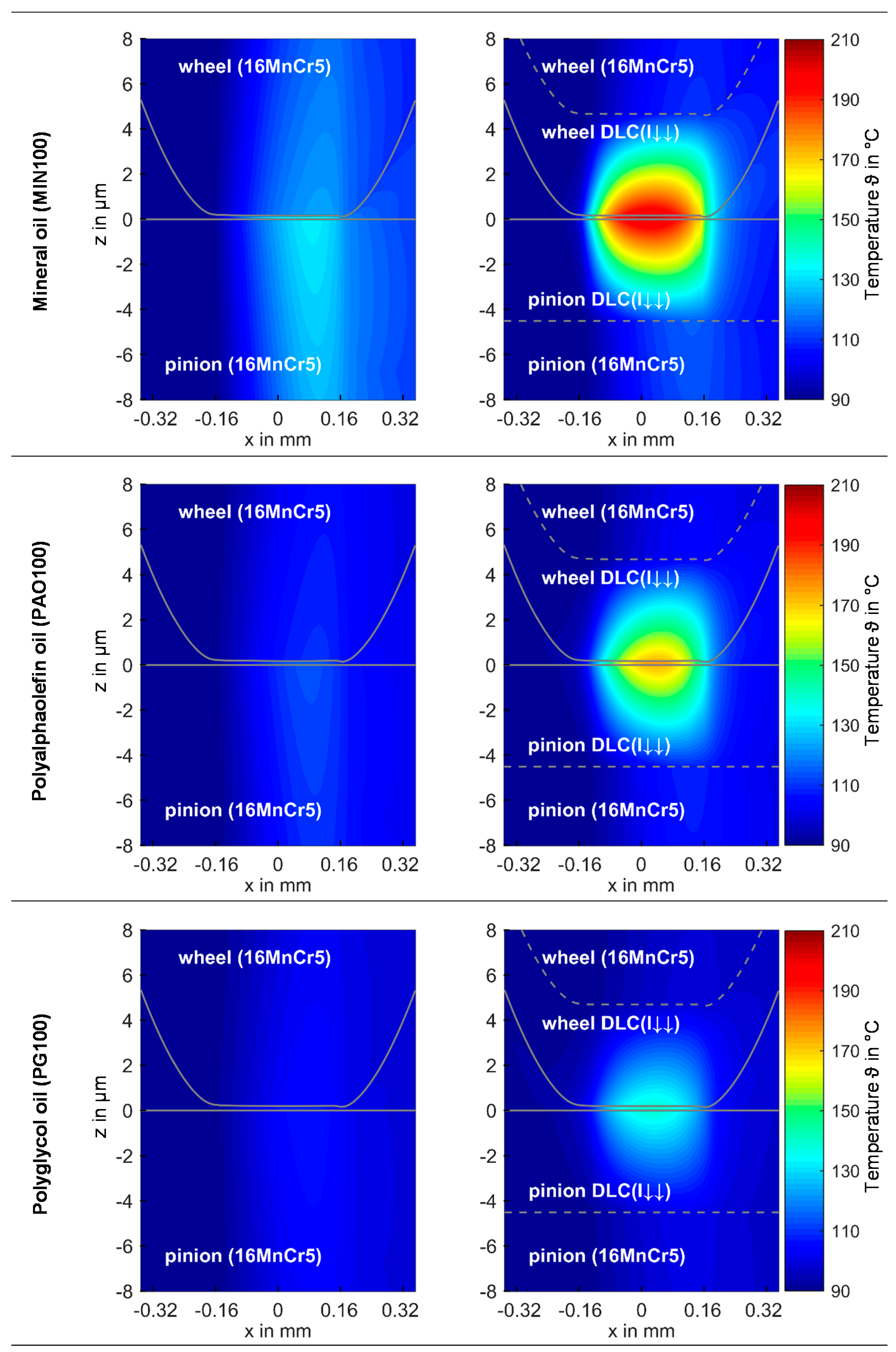
Figure 4 exemplarily shows the temperature distribution in the TEHL contact for uncoated and DLC(I↓↓) coated gears in comparison with MIN100, PAO100 and PG100 for the highest local gear power loss along the path of contact (close to B). Note that the illustration implies an undeformed lower flat body and a deformed upper roller, as considered in the equivalent contact model. MIN100, PAO100 and PG100 show different levels of the TEHL temperature due to the different fluid coefficients of friction (cf. Section 3.3). As at the considered point along the path of contact, the wheel has a higher tangential velocity than the pinion, higher temperatures occur at the pinion due to inferior heat removal. For the DLC(I↓↓) coated gears, a concentration of the temperature in the lubricant film and the coatings and corresponding higher temperatures are observed in the TEHL contact.
3.2. Minimum Film Thickness along the Path of Contact
As for , the minimum film thickness also generally shows a similar trend for the considered lubricants and coatings. After a rapid decrease at A, increases moderately as it approaches C. Between C and D, tends to decline before it rapidly increases towards E. The general trend of at A and E is strongly determined by the line load as it approaches zero. In between, , and the lubricant temperature determine the trend of . Especially near B and D, the high lubricant temperature , due to high sliding velocity, results in local viscosity reductions particularly at the constriction and, therefore, in a decrease of . In comparison with the lubricant types, MIN100 shows lower values of than PAO100 and itself shows lower values than PG100. The differences between the lubricant types have been discussed extensively by Ziegltrum et al. [20] and can be mainly traced back to different pressure viscosity coefficients and dynamic viscosities at the considered bulk temperature (cf. Table 3). MIN100 shows the lowest viscosity at bulk temperature, which affects more dominantly than the comparably higher pressure-viscosity coefficient and therefore it exhibits the lowest minimum film thickness .
All minimum film thickness values of coated gears are smaller than for uncoated gears. The reduction is most pronounced in regions with high values of and , as observed around B and D. For the DLC(I↓) coating, the maximum decrease of is for MIN100, for PAO100 and for PG100 compared to the uncoated gears. For the DLC(I↓↓) coating with much lower thermal inertia than the DLC(I↓) coating, a stronger decrease of with a maximum of for MIN100, for PAO100 and for PG 100 is observed. The reduction of the minimum film thickness for DLC coated gears can be traced back to higher local TEHL temperatures, resulting in higher local viscosity reduction at the constriction. As the thermal inertia of DLC(I↓↓) is four times lower than of DLC(I↓), the values for the DLC(I↓↓) coating are also lower due to higher TEHL temperatures. MIN100 shows the largest TEHL temperature rise for the DLC(I↓↓) and DLC(I↓) coating and, therefore, the most pronounced reduction of PAO100 and PG100 show smaller TEHL temperature rises and, consequently, smaller reductions of . The general results on the minimum film thickness are in accordance with the results of Beilicke et al. [18] and Habchi [13], where DLC coatings with low thermal inertia also show a slight reduction of .
In contrast to , the central film thickness is almost unaffected by the considered DLC coatings. The conditions at the inlet of the TEHL contact mainly determine the lubricant film formation. There, the lubricant temperatures are very similar when comparing with uncoated and coated gears (Figure 4), which is due to the constant bulk temperature considered in this study. At the pitch point, central film thicknesses of , and are obtained for MIN100, PAO100 and PG100. Note that in tribological systems, lower losses and thermal insulation effects by DLC coated gears result in lower bulk temperatures compared to uncoated gears [15,39]. This can result in an increase of the central film thickness and counteract the predicted lower values of .
3.3. Fluid Coefficient of Friction along the Path of Contact
The fluid coefficient of friction along the path of contact is derived by evaluating the lubricant’s shear stress in the middle of the lubricant film:
The general trend of the fluid coefficient of friction is very similar for the considered lubricants and uncoated gears. At C, is almost zero due to the pure rolling conditions. It strongly increases around C and shows moderate changes from B to C and C to D. As approaches A and E, it strongly decreases. The relationships and differences between the lubricants are explained in detail by the authors in [20]. The increase of besides C is mainly determined by shear thinning and the lubricant’s pressure-viscosity dependency. As the latter is most pronounced for MIN100, limiting shear stress is more directly reached than for PAO100 or PG100. between C and B and C and D is mainly determined by the sum velocity , line load and TEHL temperature and, therefore, by shear thinning, limiting shear stress and thermal effects. The drop of the line load near A and E leads to a strong reduction of the limiting shear stress , and, hence, . The inhomogeneous trend of near A and E is due to the reached minimum limiting shear stress of . Comparing the lubricant types, MIN100 shows the highest level of followed by PAO100 and PG100. This is mainly due to the different shear resistances of the lubricants described by in the TEHL simulation model.
All values of along the path of contact of coated gears are smaller compared to those of the uncoated gears. The reduction is most pronounced in regions with high TEHL temperatures, as observed around B and D. For the DLC(I↓) coating, the maximum decrease of is for MIN100, for PAO100 and for PG100 compared to uncoated gears. For the DLC(I↓↓) coating, a much stronger decrease of the values of corresponding to the clear higher TEHL temperatures is found. Compared to the uncoated gears, DLC(I↓↓) shows a maximum decrease of of for MIN100, for PAO100 and for PG100. After reaching near C, of the DLC(I↓↓) coated gears starts to more strongly decrease towards B and D. As the line load w decreases strongly towards A and E, the values of of DLC(I↓) and DLC(I↓↓) coated gears approach the values of for uncoated gears. The results on the fluid coefficient of friction are in general accordance with the results of Beilicke et al. [18], Habchi [13] and Habchi and Bair [14].
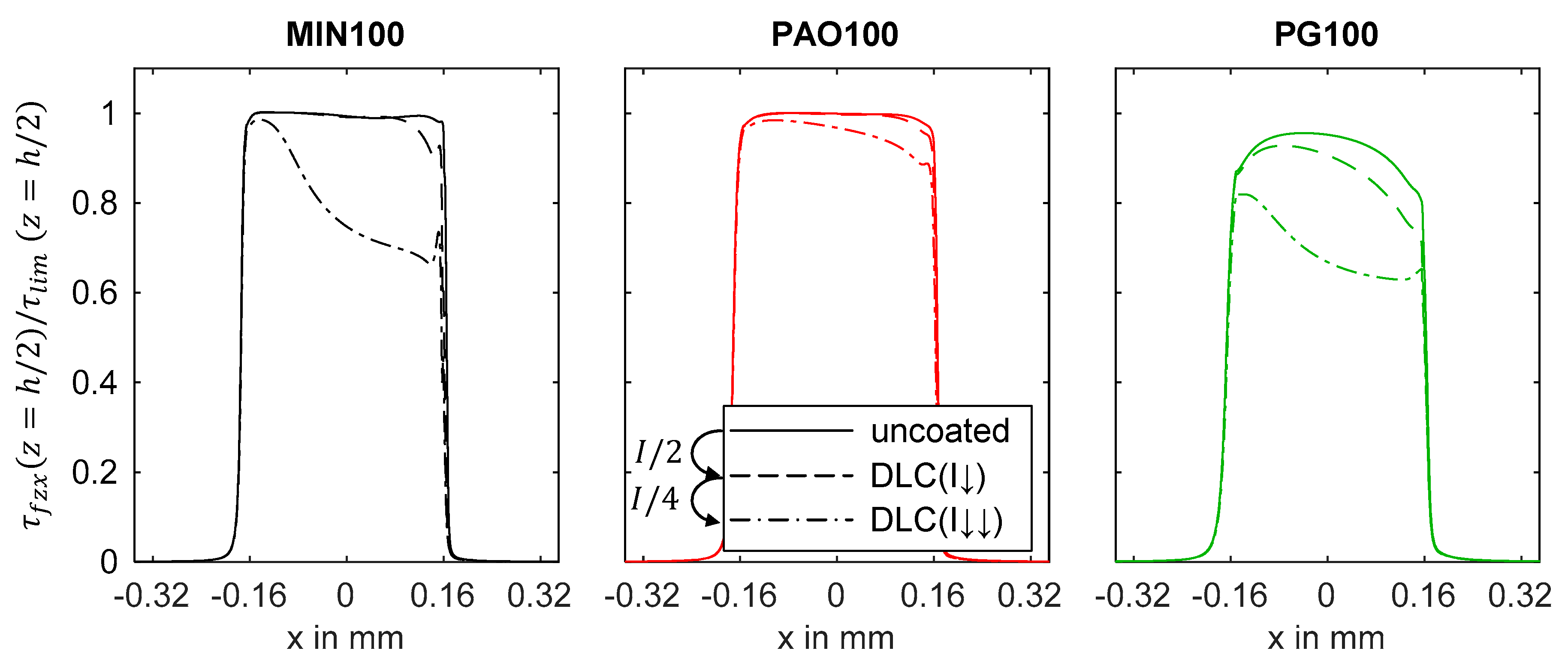
The decisive influence on is determined by the lubricant properties and their dependencies on pressure, temperature and shear rate. MIN100 shows a stronger pressure-viscosity dependency than PAO100, which itself has a stronger pressure-viscosity dependency than PG100 (Table 3). The temperature-viscosity dependency is more pronounced for MIN100 than for PAO100 and PG100. The limiting shear stress is higher for MIN100 than for PAO100, which itself is higher than for PG100 and decreases with increasing TEHL temperature. As the DLC(I↓) and DLC(I↓↓) coatings strongly influence the TEHL temperature by thermal insulation, the lubricant shear stress and therefore is influenced significantly. Figure 5 exemplarily shows the lubricant shear stress related to the limiting shear stress for the point with the highest local gear power loss along the path of contact (close to B) in a comparison between with uncoated and coated gears and among the MIN100, PAO100 and PG100 lubricants. For uncoated gears, is reached almost during the whole TEHL contact for MIN100 and PAO100 and not reached for PG100. For MIN100 and DLC(I↓↓) coated gears, is significantly smaller than over a large part of the contact area. This is due to the high TEHL temperatures, shear thinning and the corresponding reduction of effective viscosity. The trend of corresponds to the TEHL temperature distribution in Figure 4. For PAO100 and DLC(I↓↓) coated gears, the mechanisms are the same but the reduction of is less strong mainly due to a more moderate TEHL temperature rise compared to MIN100. For PG100 and DLC(I↓↓) coated gears, is, as for uncoated gears, not reached for the whole TEHL contact and is significantly smaller than . The DLC(I↓) coating shows the same relationships on a less pronounced level resulting in a lower decrease of the fluid coefficient of friction compared to the DLC(I↓↓) coating. For MIN100 and DLC(I↓) coated gears, is close to uncoated gears, because the TEHL temperature rise (cf. Section 3.1) and therefore the reduction of the effective viscosity is much less pronounced. A similar behavior can be observed for PAO100 and PG100.
Note that friction reduction is superposed by the temperature dependency of . The explanations show the complex relationships and influences of DLC coatings on friction of TEHL contacts. General conclusions are difficult to reach [14].
3.4. Local Gear Power Loss along the Path of Contact
The general trend of the local gear power loss is strongly correlated with the fluid coefficient of friction , sliding velocity and line load along the path of contact. can be written as:
is characteristic for the power input in the TEHL contact. High values of result in high maximum TEHL temperatures . As is almost zero at the pitch point C, almost no temperature rise is observed. From C to B and C to D, and strongly increase and are highest close to B. Towards A and E, and decrease strongly due to a decreasing line load. of coated gears are smaller and for coated gears are larger than for uncoated gears due to the thermal insulation. Exemplarily, for MIN100, the DLC(I↓↓) coating leads to a maximum reduction of of and, at the same time, to a maximum relative temperature rise expressed as of
3.5. Mean Fluid Coefficient of Friction of Gears
As the distribution of the coefficient of friction along the path of contact is actually not measurable, a mean fluid coefficient of friction of gears is defined [20]:
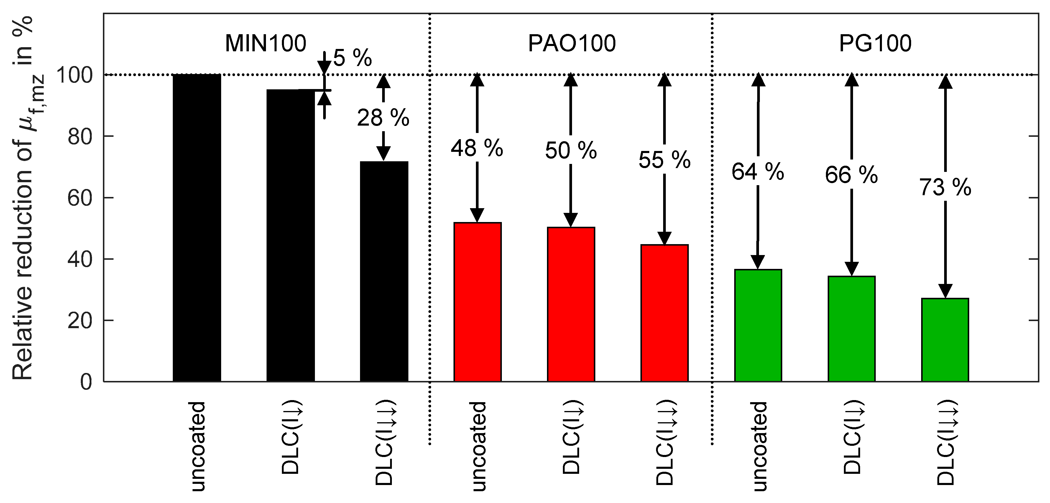
Figure 6 shows the derived relative reduction of the mean fluid coefficient of friction comparing the considered coatings and lubricant types. The reference is the uncoated gear with the lubricant MIN100. For MIN100, a reduction of of with the DLC(I↓) coating and of with the DLC(I↓↓) coating is calculated. When using the synthetic oil PAO100 instead of MIN100 for the uncoated gears, a significant reduction of is found. Applying the coatings DLC(I↓) and DLC(I↓↓) results in a further reduction by and . The lowest friction is found for the lubricant type PG100 showing a reduction of for the uncoated gears and and for DLC(I↓) coated and DLC(I↓↓) coated gears, respectively. These results are generally in good accordance with measurement results. Experimental investigations of Mayer [43] at the twin-disk test rig under fluid film lubrication on average showed, for uncoated specimens, a reduction of the coefficient of friction of for PAO100 and for PG100 compared to MIN100. Experimental studies of Hinterstoißer [37] with superfinished FZG type Cmod gears at the FZG efficiency test rig showed reductions of the mean coefficient of friction of up to about for a-C:H coated gears with MIN100. Depending on the operating conditions and the finishing of gears, the surface structure and roughness of the gear flanks can cause asperity contacts. Hence, mixed lubrication needs to be considered for a detailed comparison of simulated and measured mean coefficients of friction along the path of contact of gears [20].
4. Conclusions
In this study, the influence of a mineral, polyalphaolefin and polyglycol oil on the frictional losses of DLC coated spur gears was investigated. Thereby, a finite element based TEHL simulation was applied to the transient TEHL contact of a spur gear, taking the thermal and mechanical properties of the DLC coatings into consideration. This study focused on the effect of thermal insulation of DLC coatings on gear contacts.
The presented results show similar general trends for the coefficient of friction, minimum film thickness, local gear power loss and maximum TEHL temperature along the path of contact for uncoated gears, irrespective of the considered lubricants. The low thermal inertia of the DLC coatings results in an increase of the TEHL temperature and, subsequently, in a reduction of the effective viscosity, shear stress and, hence, fluid friction.
Mineral oil exhibits the highest coefficients of friction, followed by polyalphaolefin with a reduction of and polyglycol oil with a reduction of . When applying a DLC coating with a thermal inertia that is two times lower than the substrate material to the gears, the coefficient of friction is reduced only moderately. When applying a DLC coating with a thermal inertia that is eight times lower than the substrate material, a significant reduction of the coefficient of friction is observed. For the mineral oil, the reduction of the mean coefficient of friction along the path of contact is , for the polyalphaolefin oil and for the polyglycol oil . As the interactions in the TEHL contact are very complex, general conclusions on fluid friction are difficult. However, this study shows the potential of both, variation of lubricant type and the application of DLC coatings, for possible reductions of the frictional losses of gears.
Acknowledgments
This work was supported by the German Research Foundation (DFG) and the Technical University of Munich (TUM) in the framework of the Open Access Publishing Program.
Author Contributions
Andreas Ziegltrum performed the simulations, analyzed the results and wrote the paper. Thomas Lohner consulted regarding the design of the simulations, participated in the scientific discussions and revised the paper. Karsten Stahl supported the interpretation of the results and proof read the paper.
Conflicts of Interest
The authors declare no conflict of interest.
Nomenclature
| A | Begin of contact | Line load in | |
| Coefficients of lubricant Vogel temperature model | Film thickness length direction in | ||
| B | Begin of singular contact | Coordinate along the path of contact in | |
| C | Pitch point | Film thickness height direction in | |
| Compliance matrix | Pressure exponent of Roelands’ equation | ||
| Specific heat capacity in | |||
| D | End of singular contact | Pressure viscosity exponent in | |
| Coefficients of lubricant Bode density model | Coefficient of lubricant Bode density model in | ||
| E | End of contact | Deformation of the equivalent body in m | |
| Equivalent Young’s Modulus in | Strain tensor | ||
| Lubricant-specific parameters of | Dynamic viscosity in | ||
| Normal force in | Bulk temperature in | ||
| Lubricant film thickness in | Maximum TEHL temperature in | ||
| Constant parameter of film thickness in | Maximum TEHL temperature rise in | ||
| Minimum film thickness in | Thermal conductivity in | ||
| Effective contact length in width direction in | Equivalent Poisson’s ratio | ||
| Pressure in | Density in | ||
| Hertzian pressure in | Coefficient of the lubricant Bode density model in | ||
| Load-dependent gear power loss in | Shear stress in | ||
| Coefficient in the Roelands’ equation in | Limiting shear stress in | ||
| Radius of curvature in | Minimum limiting shear stress in | ||
| Deviation from the smooth profile in | Coefficient of friction | ||
| Slide-to-roll ratio | Mean coefficient of friction | ||
| Slip ratio | Kinematic viscosity in | ||
| Time in | |||
| Temperature in | 1 | Pinion | |
| Pinion torque in | 2 | Wheel | |
| Velocity in | f | Fluid | |
| Sliding velocity in | s | Substrate | |
| Pitch line velocity in | c | Coating | |
| Sum velocity in | |||
References
- Liu, H.; Jurkschat, T.; Lohner, T.; Stahl, K. Determination of Oil Distribution and Churning Power Loss of Gearboxes by Finite Volume CFD Method. Tribol. Int. 2017, 109, 346–354. [Google Scholar] [CrossRef]
- International Organization for Standardization. ISO TR 14179-2:2001-08: Gears—Thermal Capacity—Part 2: Thermal Load-Carrying Capacity; International Organization for Standardization: Geneva, Switzerland, 2001. [Google Scholar]
- Niemann, G.; Winter, H. Maschinenelemente—Band 2: Getriebe Allgemein, Zahnradgetriebe Grundlagen, Stirnradgetriebe, 2nd ed.; Springer: Munich, Germany, 1985. [Google Scholar]
- Jacob, W.; Moller, W. On the structure of thin hydrocarbon films. Appl. Phys. Lett. 1993, 63, 1771–1773. [Google Scholar] [CrossRef]
- Evans, R.D.; Cogdell, J.D.; Richter, G.A.; Doll, G.L. Traction of lubricated rolling contacts between thin-film coatings and steel. Tribol. Trans. 2009, 52, 106–113. [Google Scholar] [CrossRef]
- Kalin, M.; Polajnar, M. The wetting of steel, DLC coatings, ceramics and polymers with oils and water: The importance and correlations of surface energy, surface tension, contact angle and spreading. Appl. Surf. Sci. 2014, 293, 97–108. [Google Scholar] [CrossRef]
- Kalin, M.; Velkavrh, I. Non-conventional inverse-Stribeck-curve behaviour and other characteristics of DLC coatings in all lubrication regimes. Wear 2013, 297, 911–918. [Google Scholar] [CrossRef]
- Kalin, M.; Velkavrh, I.; Vizintin, J. The Stribeck curve and lubricant design for non-fully wetted surfaces. Wear 2009, 267, 1232–1240. [Google Scholar] [CrossRef]
- Björling, M.; Larsson, R.; Marklund, P. The effect of DLC coating thickness on Elastohydrodynamic friction. Tribol. Lett. 2014, 55, 353–362. [Google Scholar] [CrossRef]
- Elsharkawy, A.A.; Holmes, M.J.A.; Evans, H.P.; Snidle, R.W. Micro-elastohydrodynamic lubrication of coated cylinders using coupled differential deflection method. Proc. Inst. Mech. Eng. Part J J. Eng. Tribol. 2006, 220, 29–41. [Google Scholar] [CrossRef]
- Björling, M.; Habchi, W.; Bair, S.; Larsson, R.; Marklund, P. Friction Reduction in Elastohydrodynamic Contacts by Thin-Layer Thermal Insulation. Tribol. Lett. 2014, 53, 477–489. [Google Scholar] [CrossRef]
- Björling, M.; Isaksson, P.; Marklund, P.; Larsson, R. The influence of DLC coatings on EHL friction coefficient. Tribol. Lett. 2012, 47, 285–294. [Google Scholar] [CrossRef]
- Habchi, W. A numerical model of the solution of thermal elastohydrodynamic lubrication in coated circular contacts. Tribol. Int. 2014, 73, 57–68. [Google Scholar] [CrossRef]
- Habchi, W.; Bair, S. Effect of lubricant rheology on friction in coated elastohydrodynamic lubricated contacts. Proc. Inst. Mech. Eng. Part J J. Eng. Tribol. 2017, 231, 975–985. [Google Scholar] [CrossRef]
- Bobach, L.; Bartel, D.; Beilicke, R.; Mayer, J.; Michaelis, K.; Stahl, K.; Bachmann, S.; Schnagl, J.; Ziegele, H. Reduction in EHL Friction by a DLC Coating. Tribol. Lett. 2015, 60, 17. [Google Scholar] [CrossRef]
- Bobzin, K.; Brögelmann, T.; Stahl, K.; Michaelis, K.; Mayer, J.; Hinterstoisser, M. Friction reduction of highly-loaded rolling-sliding contacts by surface modifications under elasto-hydrodynamic lubrication. Wear 2015, 328–329, 217–228. [Google Scholar] [CrossRef]
- Lohner, T.; Mayer, J.; Stahl, K. EHL contact temperature—Comparison of theoretical and experimental determination. In Proceedings of the STLE 70th Annual Meeting & Exhibition, Dallas, TX, USA, 17–21 May 2015. [Google Scholar]
- Beilicke, R.; Bobach, L.; Bartel, D. Transient thermal elastohydrodynamic simulation of a DLC coated helical gear pair considering limiting shear stress behavior of the lubricant. Tribol. Int. 2016, 97, 136–150. [Google Scholar] [CrossRef]
- Lohner, T.; Ziegltrum, A.; Stemplinger, J.-P.; Stahl, K. Engineering Software Solution for Thermal Elastohydrodynamic Lubrication Using Multiphysics Software. Adv. Tribol. 2016, 2016, 6507203. [Google Scholar] [CrossRef]
- Ziegltrum, A.; Lohner, T.; Stahl, K. TEHL simulation on the influence of lubricants on load-dependent gear losses. Tribol. Int. 2016, 113, 252–261. [Google Scholar] [CrossRef]
- Ziegltrum, A.; Lohner, T.; Stahl, K. TEHL Simulation on the influence of lubricants on the frictional losses of DLC coated gears. In Proceedings of the 6th World Tribology Congress, Beijing, China, 17–22 September 2017. [Google Scholar]
- Yang, P.; Wen, S. A generalized Reynolds equation for non-Newtonian thermal elastohydrodynamic lubrication. ASME J. Tribol. 1990, 112, 631–636. [Google Scholar]
- Wu, S.R. A penalty formulation and numerical approximation of the Reynolds-Hertz problem of elastohydrodynamic lubrication. Int. J. Eng. Sci. 1986, 24, 1001–1013. [Google Scholar] [CrossRef]
- Reynolds, O. On the theory of the lubrication and its application to Mr. Beauchamps Tower’s experiments including an experimental determination of the viscosity of olive oil. Philos. Trans. R. Soc. Lond. 1886, 177, 157–234. [Google Scholar] [CrossRef]
- Raisin, J.; Fillot, N.; Dureisseix, D.; Vergne, P.; Lacour, V. Characteristic times in transient thermal elastohydrodynamic line contacts. Tribol. Int. 2015, 82, 472–483. [Google Scholar] [CrossRef]
- Habchi, W.; Eyheramendy, D.; Vergne, P.; Morales-Espejel, G. A Full-System Approach of the Elasto-hydrodynamic Line/Point Contact Problem. ASME J. Tribol. 2008, 130, 021501. [Google Scholar] [CrossRef]
- Hepermann, P.; Beilicke, R.; Bartel, D.; Tenberge, P.; Deters, L. Örtliche Fresstragfähigkeit Abschlussbericht—Bestimmung der Örtlichen Fresstragfähigkeit: Einfluss von Schräg- und Hochverzahnungen [Determination of the Local Scuffing Laod Capacity: Influence of Helical and High Toothing Gears]; Research Report No. 598/I, Issue 1024; Forschungsvereinigung Antriebstechnik e.V.: Frankfurt am Main, Germany, 2012. [Google Scholar]
- Vogel, H. Principle of temperature dependency of viscosity of fluids. Z. Phys. 1921, 22, 645–647. [Google Scholar]
- Fulcher, G.S. Analysis of recent measurements of the viscosity of glasses II. J. Am. Ceram. Soc. 1925, 8, 789–794. [Google Scholar] [CrossRef]
- Tammann, G.; Hesse, W. Die Abhängigkeit der Viskosität von der Temperatur bei unterkühlten Flüssigkeiten [Temperature dependency of viscosity of undercooled liquids]. Zeitschrift für Anorganische und Allgemeine Chemie 1926, 156, 245–247. [Google Scholar] [CrossRef]
- Roelands, C.J.A. Correlation Aspects of the Viscosity-Temperature Relationship of Lubricating Oil. Ph.D. Thesis, Technische Hogeschool Delft, Delft, The Netherlands, 1966. [Google Scholar]
- Wolff, R.; Kubo, A. A generalized non-Newtonian fluid model incorporated into elastohydrodynamic lubrication. J. Tribol. 1996, 118, 74–82. [Google Scholar] [CrossRef]
- Lohner, T.; Michaelis, K.; Stahl, K. Limiting shear stress formulation for TEHL simulation. In Proceedings of the 7th ECCOMAS Congress, Crete, Greece, 5–10 June 2016. [Google Scholar]
- Bode, B. Modell zur Beschreibung des Fließverhaltens von Flüssigkeiten unter hohem Druck [Model for describing the rheological behaviour of liquids under high pressure]. Tribol. Schmier 1989, 36, 182–189. [Google Scholar]
- Larsson, E.; Andersson, O. Lubricant thermal conductivity and heat capacity under high pressure. J. Eng. Tribol. 2000, 214, 337–342. [Google Scholar] [CrossRef]
- COMSOL Multiphysics, COMSOL Multiphysics Modeling Guide. COMSOL Inc. Available online: www.comsol.com (accessed on 1 April 2017).
- Hinterstoißer, M. Zur Optimierung des Wirkungsgrades von Stirnradgetrieben [On the Optimization of Gear Efficiency of Cylindrical Gear Drives]. Ph.D. Thesis, Technical University of Munich, Munich, Germany, 2013. [Google Scholar]
- Fromberger, M.; Otto, M.; Stahl, K. Erweiterung STplus Abschlussbericht—Erweiterung des FVA-Stirnradprogramms STplus [Extension of STplus]; Research Project No. 241/IX, Issue 1156; Forschungsvereinigung Antriebstechnik e.V.: Frankfurt am Main, Germany, 2015. [Google Scholar]
- Bobzin, K.; Brögelmann, T.; Kalschuer, C.; Thiex, M.; Ebner, M.; Lohner, T.; Stahl, K. A contribution to the thermal effects of DLC coatings in fluid friction in EHL contacts. Lubr. Sci. 2017. under review. [Google Scholar]
- Becker, J.; Colas, M.; Gies, A.; Hessel, S.; Karner, H.; Seibert, F.; Stelzit, T. Thermal effects influencing stability and performance of coatings in automotive applications. Surf. Coat. Technol. 2015, 284, 166–172. [Google Scholar] [CrossRef]
- Clausthal, I.T.R. Thermophysikalische Eigenschaften (Schmierstoffe)—Bestimmung und Modellierung der Thermophysikalischen Eigenschaften von Schmier- und Kraftstoffen unter Hohen Drücken [Thermophysical Properities (Lubricants)—Determination and Modeling of Thermophysical Properties of Lubricants and Fuels under High Pressures]; Research Project No. 583/I, Issue 1002; Forschungsvereinigung Antriebstechnik e.V.: Frankfurt am Main, Germany, 2013. [Google Scholar]
- Stiller, S.; Otto, M.; Stahl, K. Erweiterung Ritzelkorrekturprogramm (RIKOR) zur Bestimmung der Lastverteilung von Stirnradgetrieben [Extension of RIKOR for Determination of Load Distribution of Cylindrical Gear Drives]; Research Project No. 30/VII, Issue 1077, Version: RIKOR J; Forschungsvereinigung Antriebstechnik e.V.: Frankfurt am Main, Germany, 2013. [Google Scholar]
- Mayer, J. Einfluss der Oberfläche und des Schmierstoffs auf das Reibungsverhalten im EHD Kontakt [Influecne of Surface Texture and Lubricant on the Frictional Behavior of EHL Contacts]. Ph.D. Thesis, Technical University of Munich, Munich, Germany, 2013. [Google Scholar]
Figure 1.
Geometry plot of the considered FZG type Cmod gear.

Figure 2.
Line load , Hertzian pressure and radius of curvature (left) and sum velocity , sliding velocity , slip ratio and slide-to-roll ratio (right) along the path of contact of the considered FZG type Cmod gear.
Figure 2.
Line load , Hertzian pressure and radius of curvature (left) and sum velocity , sliding velocity , slip ratio and slide-to-roll ratio (right) along the path of contact of the considered FZG type Cmod gear.
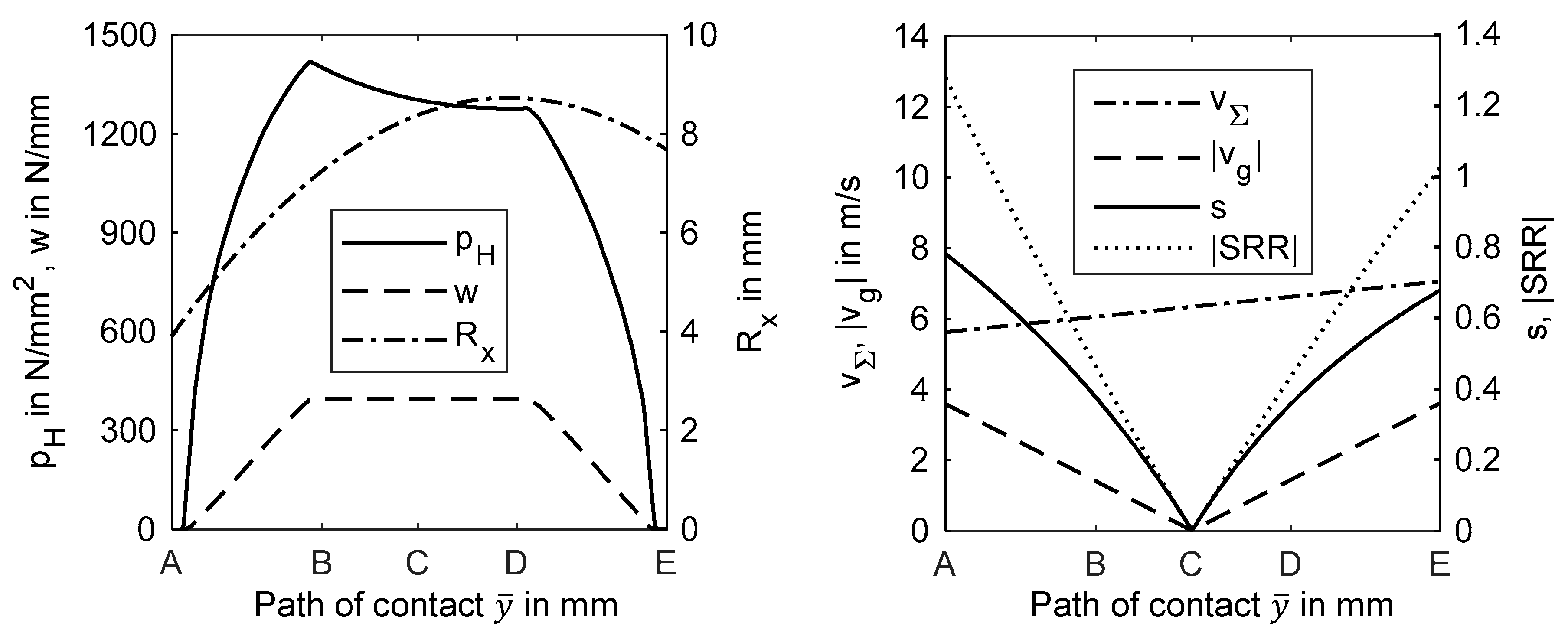
Figure 3.
Maximum TEHL temperature , minimum film thickness , fluid coefficient of friction and local gear power loss for MIN100, PAO100 and PG100 along the path of contact for uncoated (left) and coated gears (right).
Figure 3.
Maximum TEHL temperature , minimum film thickness , fluid coefficient of friction and local gear power loss for MIN100, PAO100 and PG100 along the path of contact for uncoated (left) and coated gears (right).

Figure 4.
Temperature distribution for uncoated (left) and DLC(I↓↓) coated (right) gears for MIN100, PAO100 and PG100 for the highest local gear power loss along the path of contact (close to B).
Figure 4.
Temperature distribution for uncoated (left) and DLC(I↓↓) coated (right) gears for MIN100, PAO100 and PG100 for the highest local gear power loss along the path of contact (close to B).

Figure 5.
Shear stress related to the limiting shear stress for MIN100, PAO100 and PG100 and for uncoated and coated gears for the highest local gear power loss along the path of contact.
Figure 5.
Shear stress related to the limiting shear stress for MIN100, PAO100 and PG100 and for uncoated and coated gears for the highest local gear power loss along the path of contact.

Figure 6.
Relative reduction of the mean fluid coefficient of friction along the path of contact of gears due to the considered coatings and lubricant types.
Figure 6.
Relative reduction of the mean fluid coefficient of friction along the path of contact of gears due to the considered coatings and lubricant types.


Table 1.
Gear parameters of FZG type Cmod gear (1 = pinion, 2 = wheel).
| Center distance in | |
| Number of teeth | |
| Normal module in | |
| Pressure angle in | |
| Face width in | |
| Addendum modification | |
| Tip relief in |
Table 2.
Properties of substrate material and DLC coatings.
| Material | 16MnCr5E | DLC(I↓) | DLC(I↓↓) |
|---|---|---|---|
| in | n.a. | ||
| n.a. | |||
| in | |||
| in | |||
| in | |||
| in | |||
| Coating’s thickness in | |||
Table 3.
Lubricant properties.
| Lubricant | MIN100 | PAO100 | PG100 |
|---|---|---|---|
| in | |||
| in | |||
| in | |||
| in | |||
| in | |||
| in | |||
| in | |||
| in | |||
| in | |||
| in | |||
| in | |||
| in | |||
| in | |||
| in | |||
| in | |||
| in | |||
Table 4.
Considered operating condition.
| Pinion torque in | |
| Oil temperature in | |
| Pitch line velocity in | |
| Bulk temperature in |
© 2018 by the authors. Licensee MDPI, Basel, Switzerland. This article is an open access article distributed under the terms and conditions of the Creative Commons Attribution (CC BY) license (http://creativecommons.org/licenses/by/4.0/).
Share and Cite
MDPI and ACS Style
Ziegltrum, A.; Lohner, T.; Stahl, K. TEHL Simulation on the Influence of Lubricants on the Frictional Losses of DLC Coated Gears. Lubricants 2018, 6, 17. https://doi.org/10.3390/lubricants6010017
AMA Style
Ziegltrum A, Lohner T, Stahl K. TEHL Simulation on the Influence of Lubricants on the Frictional Losses of DLC Coated Gears. Lubricants. 2018; 6(1):17. https://doi.org/10.3390/lubricants6010017
Chicago/Turabian StyleZiegltrum, Andreas, Thomas Lohner, and Karsten Stahl. 2018. "TEHL Simulation on the Influence of Lubricants on the Frictional Losses of DLC Coated Gears" Lubricants 6, no. 1: 17. https://doi.org/10.3390/lubricants6010017
Note that from the first issue of 2016, this journal uses article numbers instead of page numbers. See further details here.