A Preliminary Study to Enhance the Tribological Performance of CoCrMo Alloy by Fibre Laser Remelting for Articular Joint Implant Applications


Abstract
:
1. Introduction
2. Materials and Methodologies
2.1. Materials
2.2. Laser Remelting Experiment
2.3. Surface Morphology and Phase Structure Analysis
2.4. Tribological Measurements: Pin-On-Disk Tribometry and Dynamic Light Scattering
2.5. Surface Roughness Measurements
2.6. Vickers Microhardness Tests
3. Results and Discussion
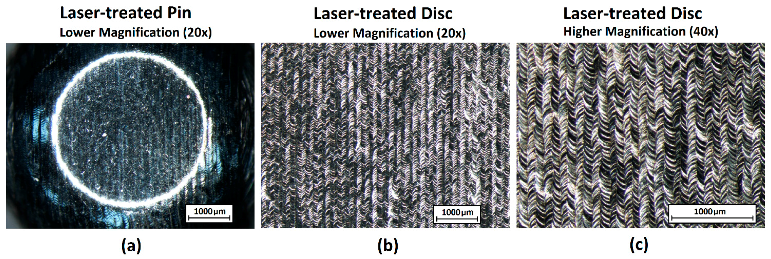
3.1. Surface Morphology Analysis
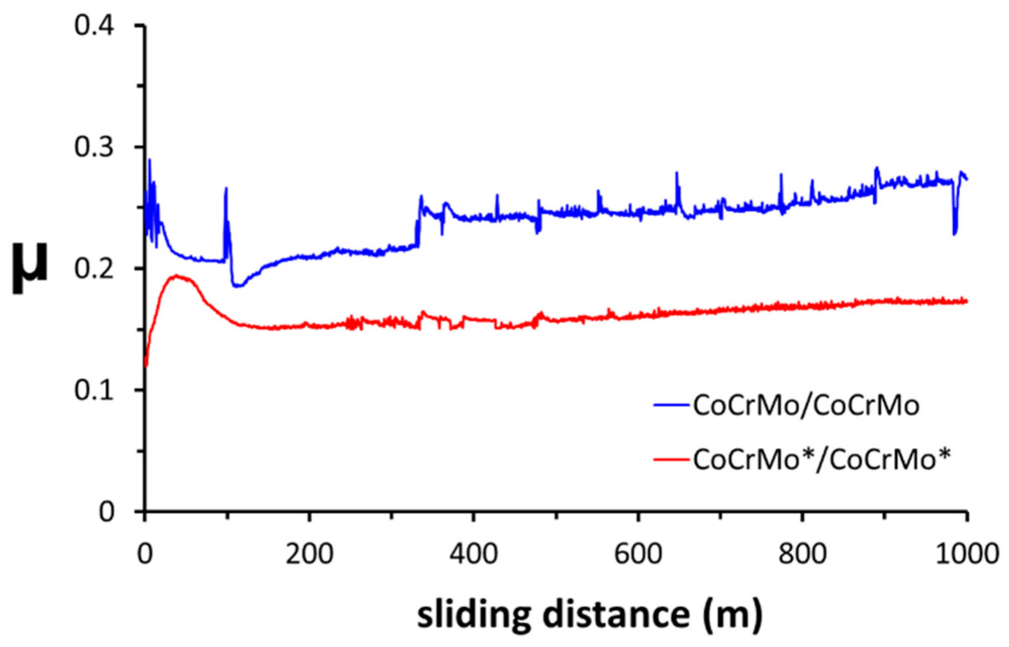
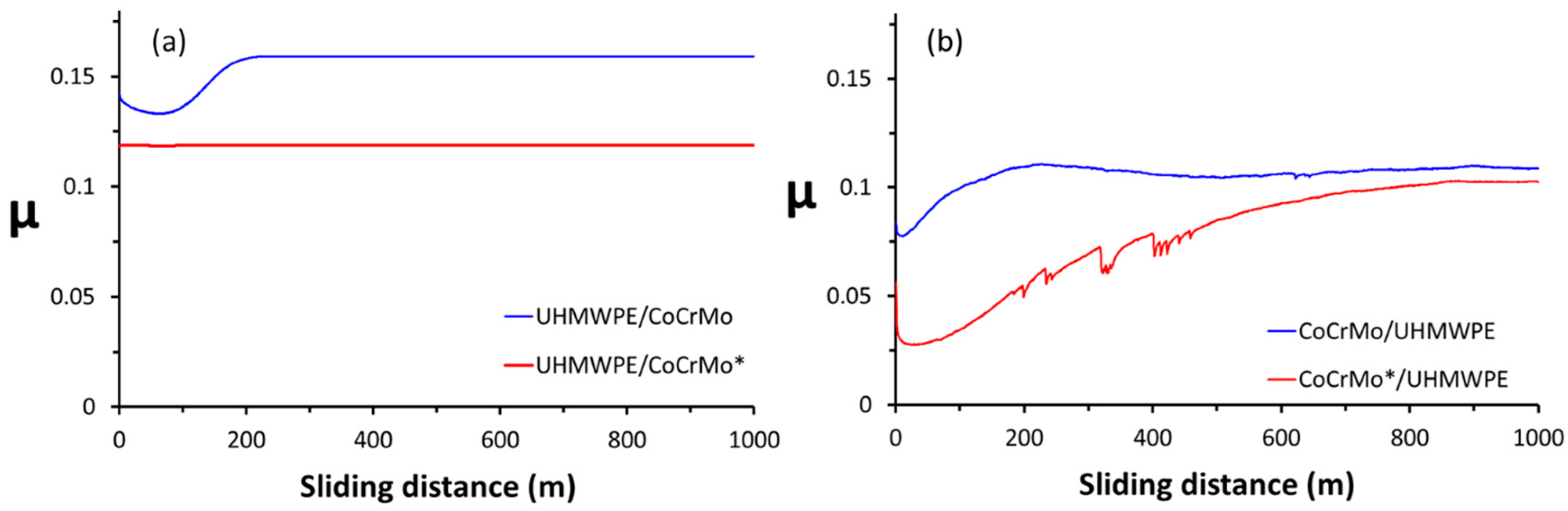
3.2. Frictional Properties
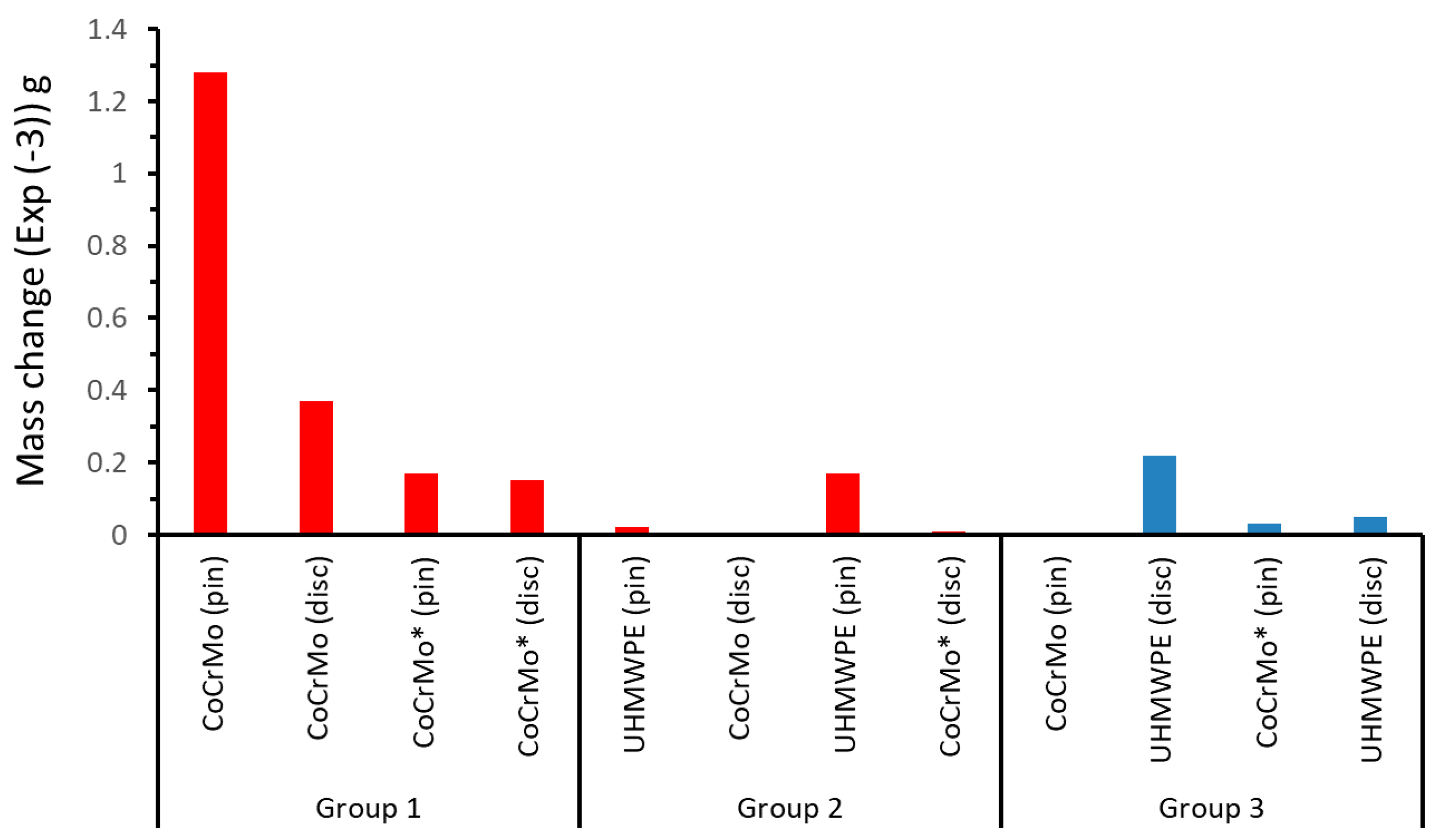
3.3. Wear Properties
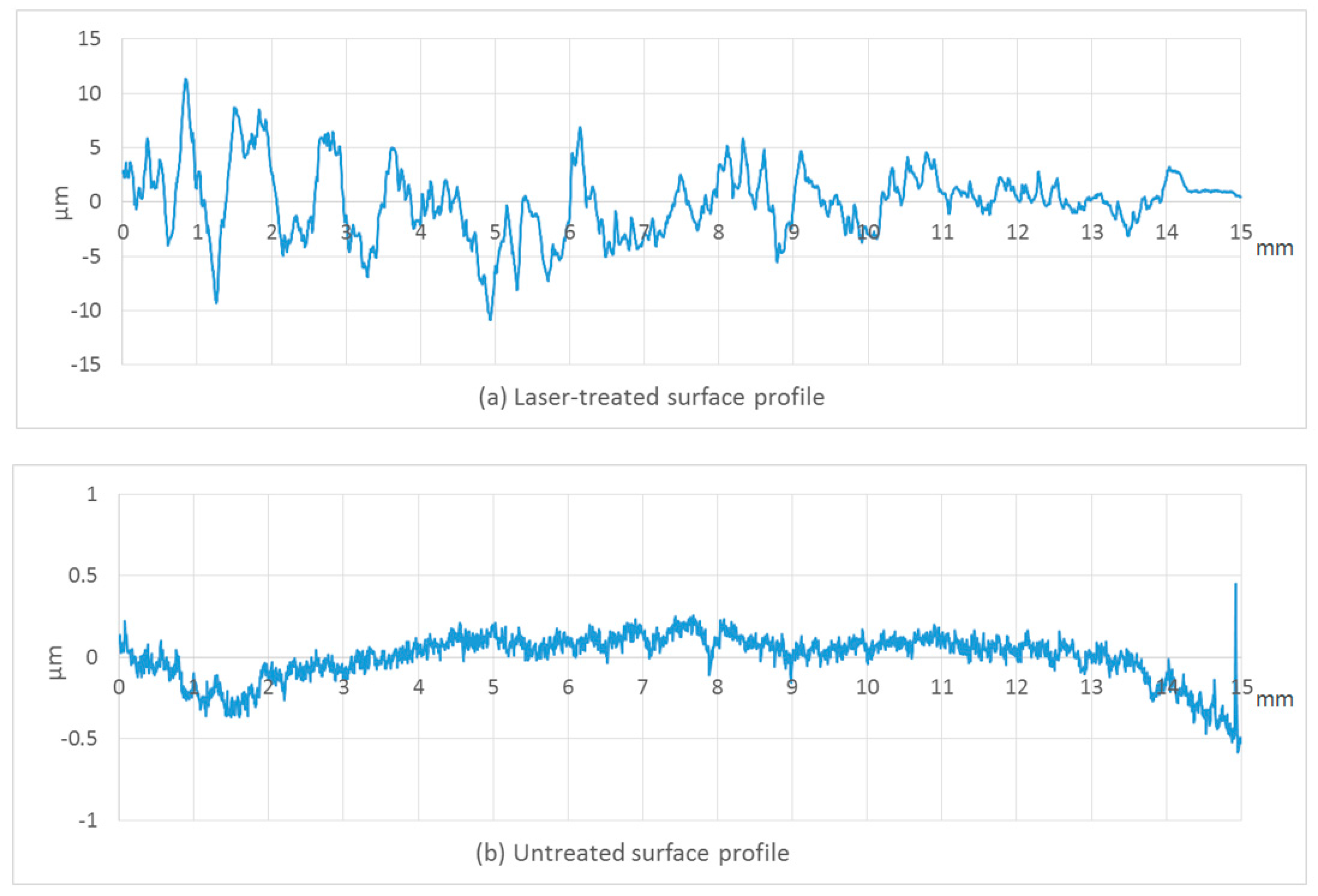
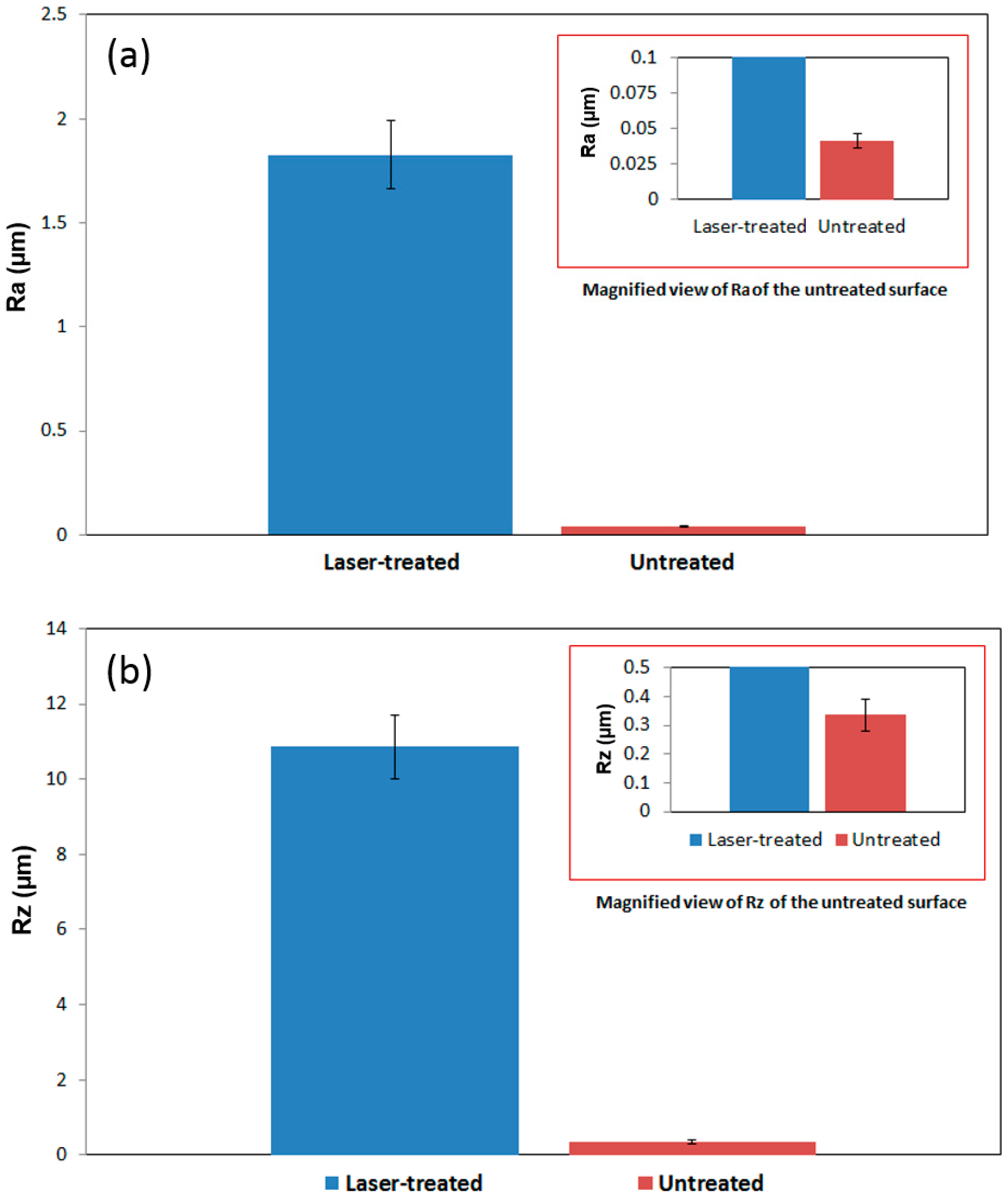
3.4. Surface Roughness Measurements
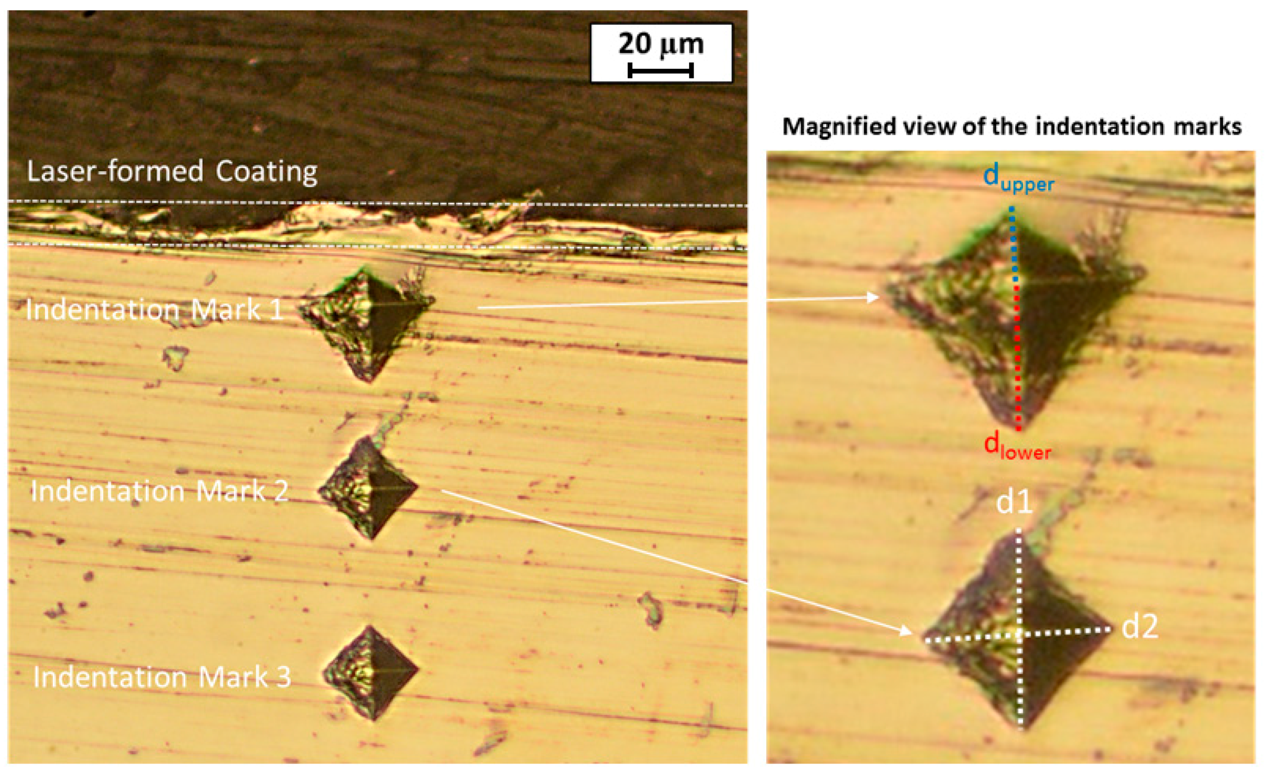
3.5. Vickers Microhardness Tests
3.6. Surface Phase Structure Analysis
4. Conclusions
- (i)
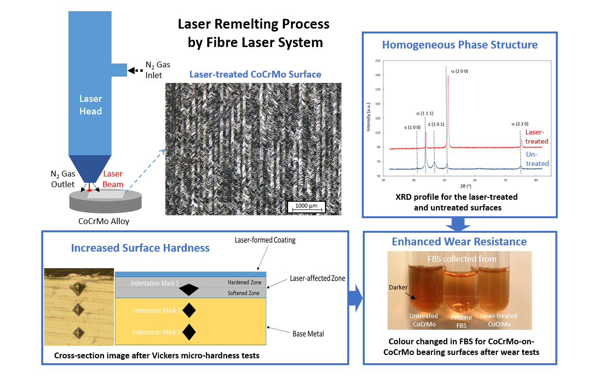
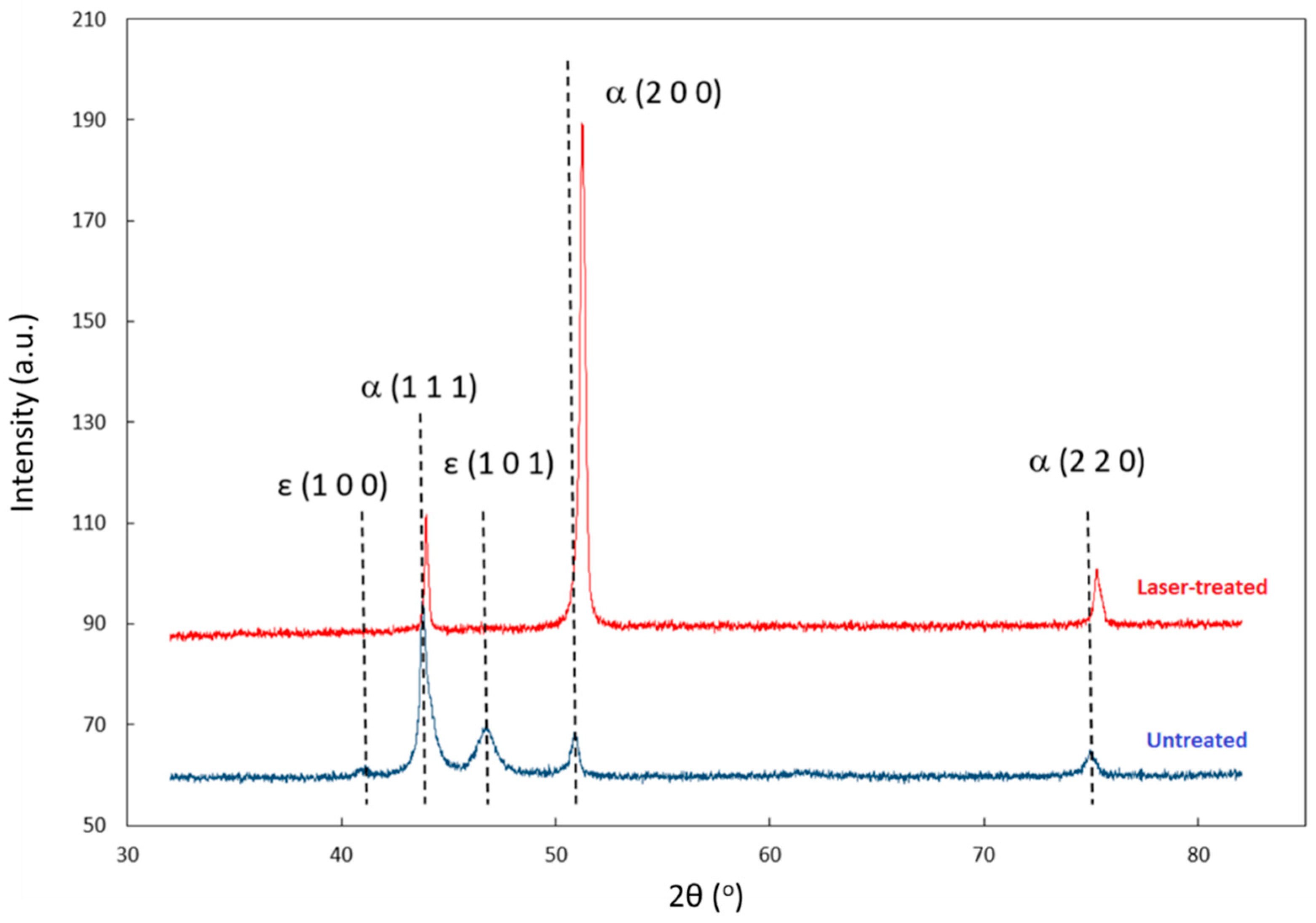
- The laser-formed coating exhibited a homogeneous phase structure. The coating showed only the α phase peaks (i.e., no ε phase detected).
- (ii)
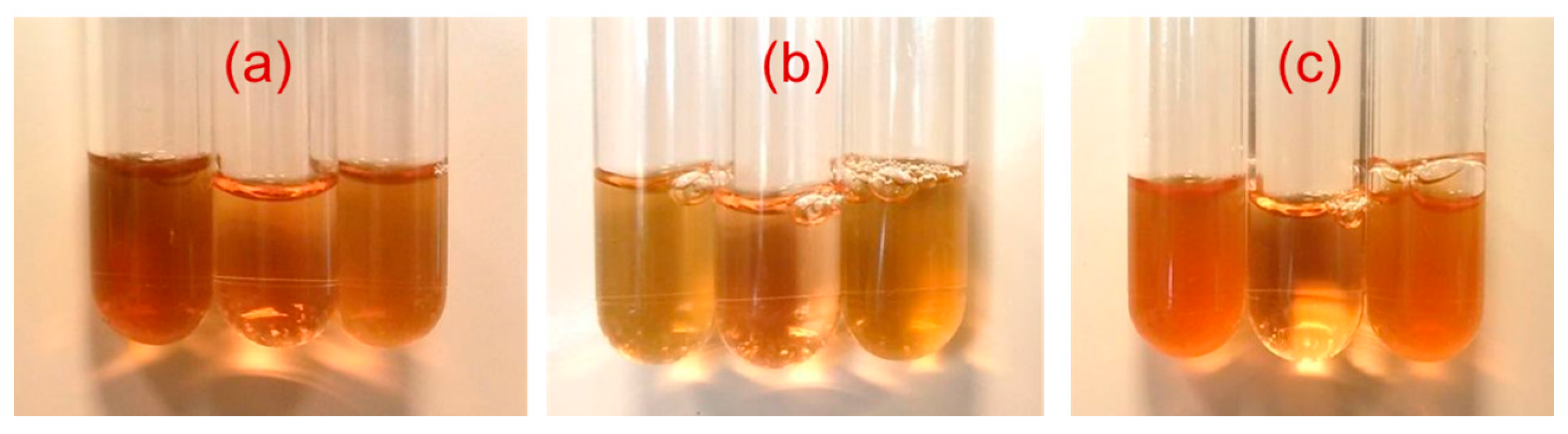
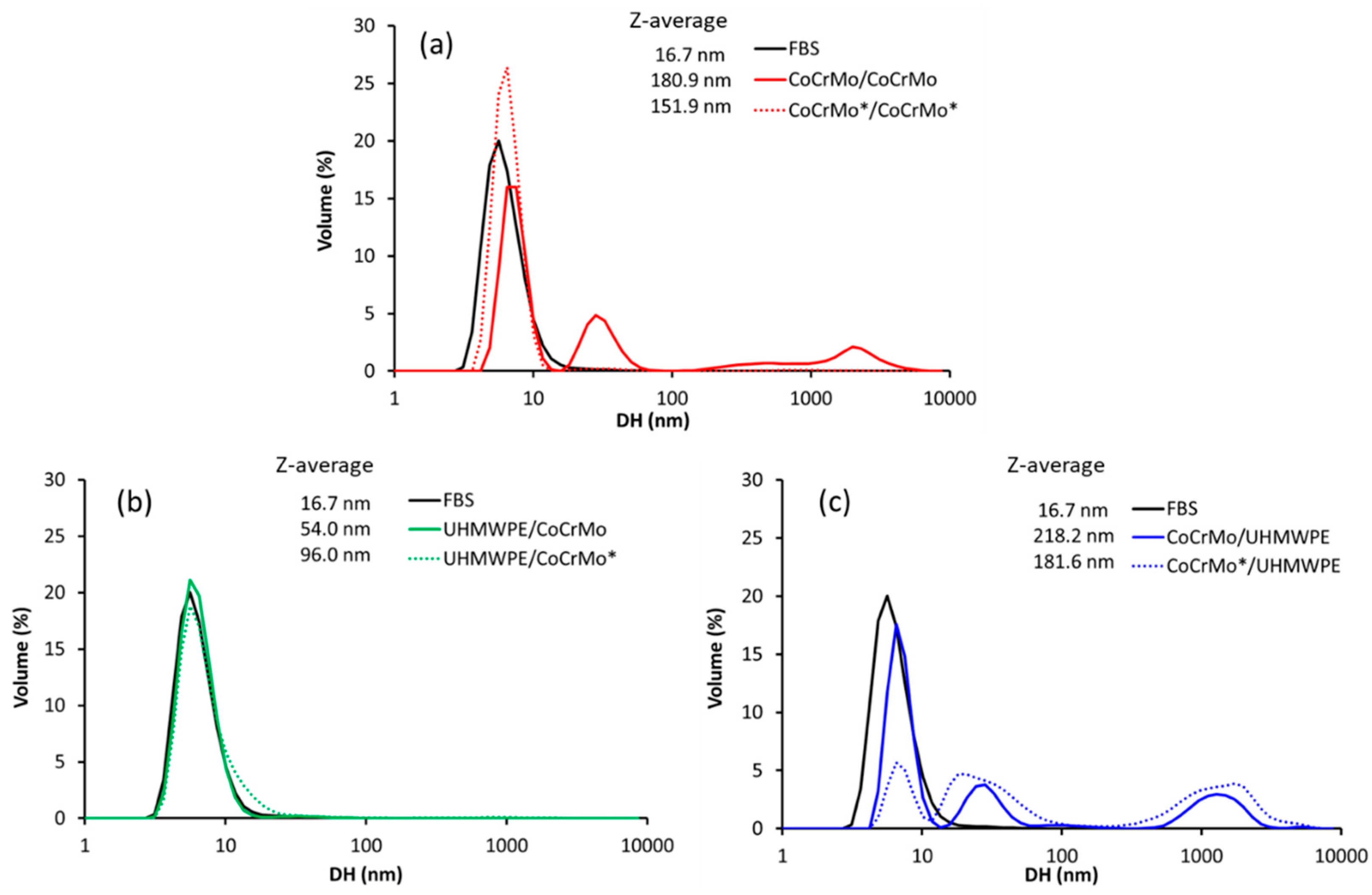
- Laser remelting of the CoCrMo surface demonstrated a friction-reducing effect for all the tribopairs (namely, (a) CoCrMo pin-on-CoCrMo disc, (b) UHMWPE pin-on-CoCrMo disc and (c) CoCrMo pin-on-UHMWPE disc).
Supplementary Materials
Acknowledgments
Author Contributions
Conflicts of Interest
References
- Health at a Glance: Europe 2016, State of Health in the EU Cycle, OECD. Available online: http://dx.doi.org/10.1787/9789264265592-en (accessed on 25 January 2018).
- Kurtz, S.M. The UHMWPE Handbook: Ultra-High Molecular Weight Polyethylene in Total Joint Replacement; Springer: New York, NY, USA, 2009. [Google Scholar]
- Knahr, K. Tribology in Total Hip Arthroplasty; Springer: New York, NY, USA, 2011. [Google Scholar]
- Learmonth, I.D. Biocompatibility: A biomechanical and biological concept in total hip replacement. Surg. J. R. Coll. Surg. Edinb. Irel. 2003, 1, 1–8. [Google Scholar] [CrossRef]
- Ingham, E.; Fisher, J. The role of macrophages in osteolysis of total joint replacement. Biomaterials 2005, 26, 1271–1286. [Google Scholar] [CrossRef] [PubMed]
- Buford, A.; Goswami, T. Review of wear mechanisms in hip implants: Paper I—General. Mater. Des. 2004, 25, 385–393. [Google Scholar] [CrossRef]
- Buford, A.; Goswami, T. Review of wear mechanisms in hip implants: Paper II—Ceramics IG004712. Mater. Des. 2004, 25, 395–405. [Google Scholar]
- Ingham, E.; Fisher, J. Biological reactions to wear debris in total joint replacement. Proc. Inst. Mech. Eng. H 2000, 214, 21–37. [Google Scholar] [CrossRef] [PubMed]
- Liu, R.; Li, X.; Hu, X.; Dong, H. Surface modification of a medical grade Co.-Cr-Mo alloy by low-temperature plasma surface alloying with nitrogen and carbon. Surf. Coat. Technol. 2013, 232, 906–911. [Google Scholar] [CrossRef]
- Wang, Q.; Zhang, L.; Dong, J. Effects of plasma nitriding on microstructure and tribological properties of CoCrMo alloy implant materials. J. Bionic Eng. 2010, 7, 337–344. [Google Scholar] [CrossRef]
- Walker, J.C.; Cook, R.B.; Murray, J.W.; Clare, A.T. Pulsed electron beam surface melting of CoCrMo alloy for biomedical applications. Wear 2013, 301, 250–256. [Google Scholar] [CrossRef]
- Galetz, M.C.; Fleischmann, E.W.; Konrad, C.H.; Schuetz, A.; Glatzel, U. Abrasion resistance of oxidized zirconium in comparison with CoCrMo and titanium nitride coatings for artificial knee joints. J. Biomed. Mater. Res. B Appl. Biomater. 2010, 93, 244–251. [Google Scholar] [CrossRef] [PubMed]
- Galetz, M.C.; Seiferth, S.H.; Theile, B.; Glatzel, U. Potential for adhesive wear in friction couples of UHMWPE running against oxidized zirconium, titanium nitride coatings, and cobalt-chromium alloys. J. Biomed. Mater. Res. B Appl. Biomater. 2010, 93, 468–475. [Google Scholar] [CrossRef] [PubMed]
- Van Hove, R.P.; Sierevelt, I.N.; van Royen, B.J.; Nolte, P.A. Titanium-nitride coating of orthopaedic implants: A review of the literature. Biomed. Res. Int. 2015, 2015, 485975. [Google Scholar] [CrossRef] [PubMed]
- Santos, C.B.; Haubold, L.; Holeczek, H.; Becker, M.; Metzner, M. Wear–corrosion resistance of DLC/CoCrMo system for medical implants with different surface finishing. Tribol. Lett. 2010, 37, 251–259. [Google Scholar] [CrossRef]
- Zhang, T.F.; Deng, Q.Y.; Liu, B.; Wu, B.J.; Jing, F.J.; Leng, Y.X.; Huang, N. Wear and corrosion properties of diamond like carbon (DLC) coating on stainless steel, CoCrMo and Ti6Al4V substrates. Surf. Coat. Technol. 2015, 273, 12–19. [Google Scholar] [CrossRef]
- Corona-Gomez, J.; Shiri, S.; Mommadtaheri, M.; Yang, Q. Adhesion enhancement of DLC on CoCrMo alloy by diamond and nitrogen incorporation for wear resistant applications. Surf. Coat. Technol. 2017, 332, 120–127. [Google Scholar] [CrossRef]
- Meacock, C.G.; Vilar, R. Structure and properties of a biomedical Co–Cr–Mo alloy produced by laser powder microdeposition. J. Laser Appl. 2009, 21, 88–95. [Google Scholar] [CrossRef]
- Chen, C.J.; Xu, X.; Cao, Q.; Zhang, M.; Chang, Q.; Zhang, S. Laser surface cladding of plastic-molded steel 718H by CoCrMo alloy. J. Mater. Eng. Perform. 2012, 21, 946–950. [Google Scholar] [CrossRef]
- Barekat, M.; Razavi, R.S.; Ghasemi, A. Nd:YAG laser cladding of Co–Cr–Mo alloy on γ-TiAl substrate. Opt. Laser Technol. 2016, 80, 145–152. [Google Scholar] [CrossRef]
- Barekat, M.; Razavi, R.S.; Ghasemi, A. High temperature oxidation behavior of laser clad Co–Cr–Mo coating on γ-TiAl substrate. J. Laser Appl. 2016, 28. [Google Scholar] [CrossRef]
- Barekat, M.; Razavi, R.S.; Ghasemi, A. Wear behavior of laser-cladded Co–Cr–Mo coating on γ-tial substrate. J. Mater. Eng. Perform. 2017, 26, 3226–3238. [Google Scholar] [CrossRef]
- Monroy, K.P.; Delgado, J.; Sereno, L.; Ciurana, J.; Hendrichs, N.J. Effects of the selective laser melting manufacturing process on the properties of CoCrMo single tracks. Met. Mater. Int. 2014, 20, 873–884. [Google Scholar] [CrossRef]
- Mantrala, K.M.; Das, M.; Balla, V.K.; Rao, C.S.; Rao, V.V.S. Laser-deposited CoCrMo alloy: Microstructure, wear, and electrochemical properties. J. Mater. Res. 2014, 29, 2021–2027. [Google Scholar] [CrossRef]
- Mantrala, K.M.; Das, M.; Balla, V.K.; Rao, C.S.; Rao, V.V.S. Additive manufacturing of Co–Cr–Mo alloy: Influence of heat treatment on microstructure, tribological, and electrochemical properties. Front. Mech. Eng. 2015, 1, 1–7. [Google Scholar] [CrossRef]
- Sahasrabudhe, H.; Bose, S.; Bandyopadhyay, A. Laser processed calcium phosphate reinforced CoCrMo for load-bearing applications: Processing and wear induced damage evaluation. Acta Biomater. 2018, 66, 118–128. [Google Scholar] [CrossRef] [PubMed]
- Chan, C.W.; Lee, S.; Smith, G.C.; Sarri, G.; Ng, C.H.; Sharba, A.; Man, H.C. Enhancement of wear and corrosion resistance of beta titanium alloy by laser gas alloying with nitrogen. Appl. Surf. Sci. 2016, 367, 80–90. [Google Scholar] [CrossRef] [Green Version]
- Chan, C.W.; Lee, S.; Smith, G.C.; Donaghy, C. Fibre laser nitriding of titanium and its alloy in open atmosphere for orthopaedic implant applications: Investigations on surface quality, microstructure and tribological properties. Surf. Coat. Technol. 2017, 309, 628–640. [Google Scholar] [CrossRef]
- Temmler, A.; Willenborg, E.; Wissenbach, K. Design surfaces by laser remelting. Phys. Procedia 2011, 12, 419–430. [Google Scholar] [CrossRef]
- Temmler, A.; Schmickler, T.; Willenborg, E. Surface structuring by laser remelting of Inconcel 718. In Proceedings of the Lasers in Manufacturing Conference, Munich, Germany, 22–24 June 2015. [Google Scholar]
- Yasa, E.; Kruth, J. Application of laser re-melting on selective laser melting parts. Adv. Prod. Eng. Manag. 2011, 6, 259–270. [Google Scholar]
- Dong, C.; Gu, Y.; Zhong, M.; Li, L.; Ma, M.; Liu, W. The effect of laser remelting in the formation of tunable nanoporous Mn structures on mild steel substrates. Appl. Surf. Sci. 2011, 257, 2467–2473. [Google Scholar] [CrossRef]
- Guo, H.; Tian, Z.; Huang, Y.; Yang, H. Microstructure and tribological properties of laser-remelted Ni-based WC coatings obtained by plasma spraying. J. Russ. Laser Res. 2015, 36, 48–58. [Google Scholar] [CrossRef]
- Vaithilingam, J.; Goodridge, R.D.; Hague, R.J.M.; Christie, S.D.R.; Edmonds, S. The effect of laser remelting on the surface chemistry of Ti6Al4V components fabricated by selective laser melting. J. Mater. Process. Technol. 2016, 232, 1–8. [Google Scholar] [CrossRef] [Green Version]
- Akinlabi, E.T.; Mahamood, R.M.; Akinlabi, S.A. Advanced Manufacturing Techniques Using Laser Material Processing; IGI Global: Hershey, PA, USA, 2016. [Google Scholar]
- Chan, C.W.; Carson, L.; Smith, G.C.; Morelli, A.; Lee, S. Enhancing the antibacterial performance of orthopaedic implant materials by fibre laser surface engineering. Appl. Surf. Sci. 2017, 404, 67–81. [Google Scholar] [CrossRef]
- Cullity, B.D. Elements of X-ray Diffraction; Addison-Wesley Publishing Co. Inc.: Boston, MA, USA, 1978. [Google Scholar]
- X-ray Mass Attenuation Coefficients. Available online: https://physics.nist.gov/PhysRefData/XrayMassCoef/tab3.html (accessed on 14 February 2018).
- Guo, Z.; Pang, X.; Yan, Y.; Gao, K.; Volinsky, A.A.; Zhang, T.Y. CoCrMo alloy for orthopaedic implant application enhanced corrosion and tribocorrosion properties by nitrogen implantation. Appl. Surf. Sci. 2015, 347, 23–34. [Google Scholar] [CrossRef]
- Morillo, C.; Sawae, Y.; Murakami, T. Effect of bovine serum constituents on the surface of the tribological pair alumina/alumina nanocomposites for total hip replacement. Tribol. Int. 2010, 43, 1158–1162. [Google Scholar] [CrossRef]
- Bortel, E.L.; Charbonnier, B.; Heuberger, R. Development of a synthetic synovial fluid for tribological testing. Lubricants 2015, 3, 664–686. [Google Scholar] [CrossRef]
- Lee, S.; Heuberger, M.; Rousset, P.; Spencer, N.D. A tribological model for chocolate in the mouth: General implications for slurry-lubricated hard/soft sliding counterfaces. Tribol. Lett. 2004, 16, 239–249. [Google Scholar] [CrossRef]
- Afftato, S.; Vandelli, C.; Bordini, B.; Toni, A. Fluid absorption study in Ultra-high molecular weight polyethylene (UHMWPE) sterilized and unsterilized acetabular cups. Proc. Inst. Mech. Eng. H 2001, 215, 107–111. [Google Scholar] [CrossRef] [PubMed]
- Yao, J.Q.; Blanchet, T.A.; Murphy, D.J.; Laurent, M.P. Effect of fluid absorption on the wear resistance of UHMWPE orthopaedic bearing surfaces. Wear 2003, 255, 1113–1120. [Google Scholar] [CrossRef]
- Jiang, H.; Browning, R.; Fincher, J.; Gasbarro, A.; Jones, S.; Sue, H.J. Influence of surface roughness and contact load on friction coefficient and scratch behavior of thermoplastic olefins. Appl. Surf. Sci. 2008, 254, 4494–4499. [Google Scholar] [CrossRef]
- Jeong, H.; Erb, U.; Aust, K.T.; Palumbo, G. The relationship between hardness and abrasive wear resistance of electrodeposited nanocrystalline Ni–P coatings. Scr. Mater. 2003, 48, 1067–1072. [Google Scholar] [CrossRef]
- Liao, Y.; Pourzal, R.; Stemmer, P.; Wimmer, M.A.; Jacobs, J.J.; Fischer, A.; Marks, L.D. New insights into hard phases of cocrmo metal-on-metal hip replacements. J. Mech. Behav. Biomed. Mater. 2012, 12, 39–49. [Google Scholar] [CrossRef] [PubMed]


| Peak Assignment | Measured Peak Position | |
|---|---|---|
| Before Laser Remelting | After Laser Remelting | |
| α (100)/ε (100) | 41.1 | |
| α (111) | 43.8 | 44 |
| ε (101) | 46.9 | |
| α (200) | 51 | 51.2 |
| α (220)/ε (110) | 75.1 | 75.3 |
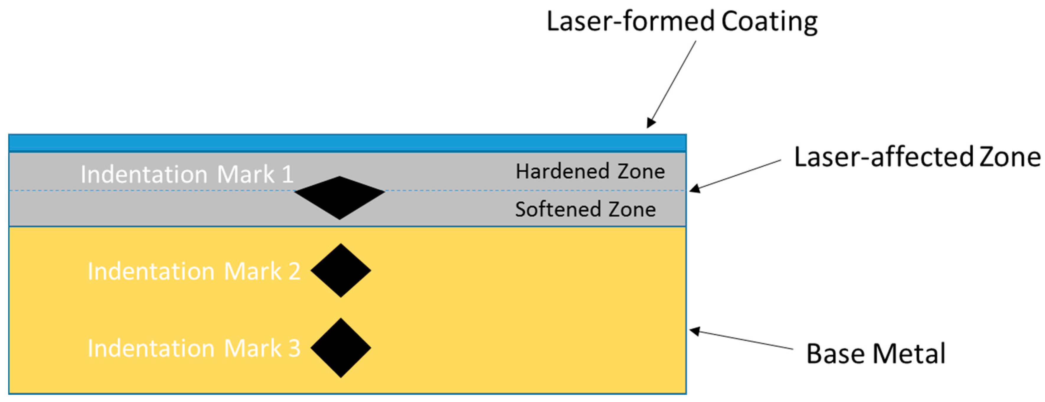
| Indentation Mark 1 | Indentation Mark 2 | Indentation Mark 3 | |
|---|---|---|---|
| Diagonal of the upper half area, dupper (μm) | Diagonal of the lower half area, dlower (μm) | Half of the average diagonal (d1 + d2)/4 (μm) | |
| 12.6 | 22.4 | 15.4 | 15.0 |
© 2018 by the authors. Licensee MDPI, Basel, Switzerland. This article is an open access article distributed under the terms and conditions of the Creative Commons Attribution (CC BY) license (http://creativecommons.org/licenses/by/4.0/).
Share and Cite
Chan, C.-W.; Smith, G.C.; Lee, S. A Preliminary Study to Enhance the Tribological Performance of CoCrMo Alloy by Fibre Laser Remelting for Articular Joint Implant Applications. Lubricants 2018, 6, 24. https://doi.org/10.3390/lubricants6010024
Chan C-W, Smith GC, Lee S. A Preliminary Study to Enhance the Tribological Performance of CoCrMo Alloy by Fibre Laser Remelting for Articular Joint Implant Applications. Lubricants. 2018; 6(1):24. https://doi.org/10.3390/lubricants6010024
Chicago/Turabian StyleChan, Chi-Wai, Graham C. Smith, and Seunghwan Lee. 2018. "A Preliminary Study to Enhance the Tribological Performance of CoCrMo Alloy by Fibre Laser Remelting for Articular Joint Implant Applications" Lubricants 6, no. 1: 24. https://doi.org/10.3390/lubricants6010024