Pathways of Dissipation of Frictional Energy under Boundary Lubricated Sliding Wear of Martensitic Materials


Materials Science and Engineering, University of Duisburg-Essen, Duisburg 47057, Germany
*
Author to whom correspondence should be addressed.
Lubricants 2018, 6(2), 34; https://doi.org/10.3390/lubricants6020034
Submission received: 6 March 2018
/
Revised: 26 March 2018
/
Accepted: 3 April 2018
/
Published: 11 April 2018
(This article belongs to the Special Issue Applied Nanotribology)
Abstract
:The challenges of technical systems subjected to friction and wear become more demanding with steadily increasing stresses. Besides safety matters, failure of tribologically loaded systems can cause tremendous maintenance costs. Because of the lack of a general wear prediction model, tribometer tests must be used in order to investigate wear behaviour of materials in certain tribological systems. Any well-aimed optimizations of tribological contacts requires a comprehensive understanding of friction and wear mechanisms. Otherwise the transferability into technical applications is questionable because of the wide range of applied loads, lubrication conditions, and materials microstructures. In this study, specimens with different topographies and subsurface microstructures were investigated prior to and after tribological testing. The analyses of surface and subsurface characteristics were performed by means of complementary high-resolution electron-microscopy techniques. The study attempted to link the findings to the wear behavior in order to gain information about the pathways of dissipation and transformation of frictional energy into wear. It was found that the dissipation pathways of base body and counter body were different, resulting in diverse tribological behaviour. Nonetheless, the presence of a near-surface grain-refined layers (tribomaterial) supported by a sub-surface strain gradient appears to provide a beneficial influence. Despite the fact that any direct or even conclusive relation to the topographies or subsurface microstructures cannot be given, the discussion provides some hints on how to analyse such systems for their characteristic mechanisms. In addition to the capability of such approach as one step of understanding, its limitations are shown and briefly discussed as well.
1. Introduction
Friction and wear, their relation and possible transition criteria for acting wear mechanisms have been described on all scales over the last 40 years by many authors, e.g., [1,2,3,4,5,6]. By relating material loss and dissipated frictional energy, several studies implied even a linear trend [3,7,8,9,10]. Other results have also been reported, e.g., by [11], which demonstrated a relation between energy-based wear rate and the acting wear mechanisms under multidirectional sliding. Shakhvorostov et al. tried to quantify terms of energy dissipation of a lubricated steel/cast iron contact, using online tribometry. It was found that approximately 70% was dissipated in heat and the second largest part was represented by material transformation processes [12]. Thus, the latter were investigated in parallel but could also not be directly related to a certain frictional or wear behaviour [13,14,15,16].
The reasons might be the multiple and interacting pathways and elementary processes of how frictional work is dissipated. In addition, they act on completely different time scales, e.g., as accumulation of cyclic plastic strains resulting in, e.g., dislocation cells or phase transformations [17,18]. In contrast, monotonic plastic strains led to grain refinement and shear band formation [19,20]. However, the biggest problem in the authors’ opinion stems from the fact that under mild and ultra-mild wear, the contact area, which brings about the measured frictional force, is orders of magnitude bigger than the area in which wear particles are generated [21]. Finally, the amount of particles generated must not match those being ejected from the system and, therefore, allow to be measured as wear loss [22]. Moreover, material loss can also be brought about by tribocorrosion and the steady release of metal ions, which might be triggered by friction but must not contribute to it. As a conclusion, we have to understand that friction signals from tribometers cannot be related to wear. Nonetheless, the pathways of dissipation appear interesting in order to qualitatively gain information about the resulting mechanisms and underlying elementary processes. This should enable us to optimize tribosystem by whatever well-aimed means, instead of trial-and-error, regarding, e.g., material selection, heat treatment, and/or surface topography.
Here we simply try to follow the paths of dissipation by high-resolution microscopy from different initial deformation states caused by machining of martensitic materials. By adding oil lubricants and using certain loading parameters, tribocorrosion should be suppressed. Thus, we maintained that the final materials loss is brought about by mostly mechanically dominated mechanisms under mild- and ultra-mild sliding wear.
In sliding wear, mild and severe can be roughly distinguished by the characteristics of contact mechanics, e.g., the plasticity index [23]. Ultra-mild wear is characterized by a linear wear rate less than about 10 nm/h. This number is a criterion for piston ring wear that would allow for a minimum of 200,000 km of a passenger car engine without substantial wear. It is chosen absolutely voluntarily in order to distinguish between ultra-mild wear and mild wear. While most laboratory tribometers for time reasons run under mild-wear conditions with a wear rate more than 1000 times bigger, most parts in application would require ultra-mild wear for a sufficient lifetime. Nonetheless, all these terms are not standardized and the regimes might overlap.
This paper does not try to render a conclusive explanation about friction and wear behaviour of martensitic materials. It should only show that such analyses are worthwhile in order to understand it, even though similar wear appearances might be related to completely different tribological behaviour.
2. Materials and Methods
2.1. Materials
2.1.1. Carburized Steel 18CrNiMo7-6
The standard case hardening steel 18CrNiMo7-6 (1.6587, SAE 18NCD6) was carburized to a surface hardness of 650 ± 24 HV10 and case hardening depth (CSD) of about 1.7 mm (Figure 1). Such hardening state is similar to that for gear applications [24]. The near surface martensite is characterized by microcrystalline plates and less than 2 vol % of retained austenite. It should be mentioned here that after the selected standard tempering treatment of carburizing no cementite precipitates have been found. As in gear boxes, this carburized steel was used to run in a self-mating tribocouple designated as CS/CS (Table 1).
2.1.2. Flame-Hardened Cast Iron EN HJS-HB265
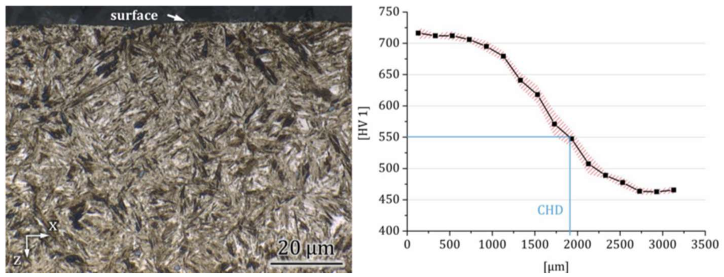
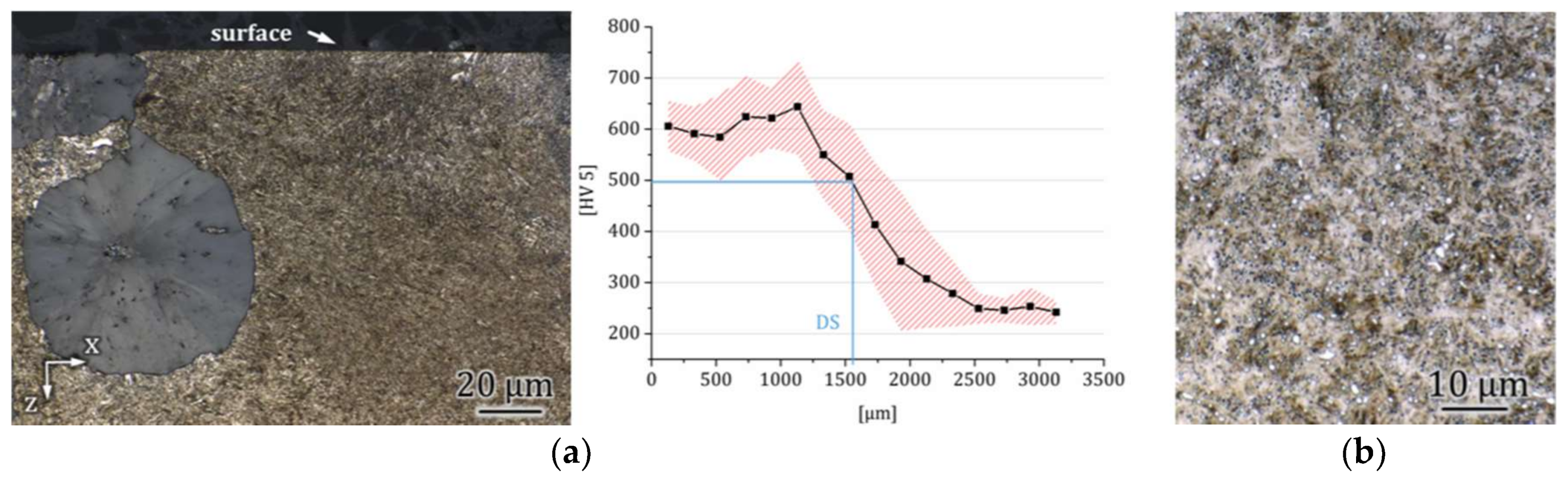
Spheroidal cast irons like EN GJS-HB265 (EN JS2070) are characterized by globular precipitation of graphite. This leads to higher ductility compared to cast iron with vermicular or lamellar graphite precipitates. Hence, they are also referred to as ductile cast iron. Due to their good mechanical properties and castability, they are used in complex and highly loaded parts, like engine components such as crankshafts or pistons. The cast iron samples were flame hardened to about 700 HV10 and a conventional hardening depth (DS) of about 1.7 mm (Figure 2a). According to typical applications, the flame hardened cast iron was used to run in a non-self-mating tribocouple designated as CI/BS against the standard ball bearing steel 100Cr6 (1.3505, AISI 52100) with a hardness of 61 HRC (Figure 2b).
2.1.3. Surface Preparation
The samples were machined using different processes, in order to investigate how the surface topography affects the friction and wear behavior:
- milled—leaving a periodic semi-circled surface;
- ground—to decrease the surface roughness after milling;
- milled + finished—to reduce the peak height while preserving the valleys;
- polished—serving as a reference sample.
Further details about the production processes can be found in [25].
2.2. Laboratory Tribosystems and Analyses
The reciprocating sliding wear tests were conducted in the ball-on-plane configuration. The test parameters are given in Table 1. Self-mating carburized steel tribocouples (CS/CS) were tested at room temperature and industrial gear oil was used as lubricant. The cast iron/bearing steel couples (CI/BS) were performed at 80 °C in engine oil. Based on pilot tests, the normal force was set to 30 N rendering a maximum Hertzian contact pressure of 1.18 GPa. This made sure that the generation of tribomaterial is basically possible. It has been shown in a parallel investigation that too low loads do not generated a tribolayer, while too severe loads destroy it immediately [26]. Others showed that the test frequency might influence the acting mechanisms of martensitic tribocouples under reciprocating sliding wear in ambient air [27]. All systems were run under boundary lubrication conditions and the wear rates were measured by subtracting the surface profiles before and after the tests as published in [28,29]. This method allows for a reproducibility of the volumetric wear rate of about ±10%.
2.3. Metallography and Microscopy
2.3.1. Light Microscopy and Hardness Measurements
For a first examination of the wear tracks and microstructures a standard optical microscope (BX41, Olympus, Hamburg, Germany) was used. The samples were cleaned in an ultrasonic bath with ethanol before analysis of the wear tracks. Cross-sections were prepared by means of a precision cutting machine (Accutom-50, Struers, Ballerup, Denmark). Hot mounting was carried out by pressing the samples (Simplimet 1000, Buehler, Lake Bluff, IL, USA) in a graphite filled polymer (Technotherm 3000, Heraeus Kulzer, Hanau, Germany) followed by grinding using 320–800 SiC grit papers and polishing down to 1 μm diamond suspension (Rotopol-31, Struers, Willich, Germany). In order to reveal the microstructure, the samples were etched in 2% nitric acid for a few seconds. Hardness measurements were conducted on cross-sections according to DIN EN ISO 6507-1 using a Zwick hardness testing device (Typ 3212, Zwick, Ulm, Germany).
2.3.2. Scanning-Electron Microscopy (SEM)
For a more detailed analysis of the wear tracks and microstructures of the samples a FE-SEM (LEO 1530 Gemini, Zeiss, Oberkochen, Germany) was applied. Micrographs were obtained in secondary electron (SE) imaging mode. Chemical analyses were performed by electron dispersive x-ray spectroscopy (EDS) with a silicon drift detector (Apollo X, Ametek, Wiesbaden, Germany). Electron backscattered diffraction (EBSD) provides information of the crystal structures and lattice parameters. In this work, kernel average misorientation (KAM) diagrams are used, indicating lattice distortions. KAM is calculated by averaging the misorientations of surrounding data points with regard to the point at the center. In this case, the parameters were set to a radius of three neighbouring data points. EBSD analyses were carried out at an acceleration voltage of 20 kV and the step size was set to 80 nm. A Digiview IV camera (Ametek, Wiesbaden, Germany) and corresponding analytical software (OIM 6.2, Ametek, Wiesbaden, Germany) were used for the analyses.
Cross-sections were prepared parallel to the sliding direction using a cross section polisher (IB-09010CP, Jeol, Freising, Germany). First the samples were wet-cut to a desired length and height. Afterwards, a 300 μm thick silicon wafer was glued on top by a two-component adhesive (G2, Gatan, Munich, Germany). Subsequently, one side of the sample was ground using 1200 grit SiC paper in order to reach the position of interest. This side was then polished by Ar+ ions at 5 kV and approximately 130 μA for several hours (IB-09010CP, Jeol, Freising, Germany).
2.3.3. Transmission Electron Microscopy (TEM)
Sample preparation by means of focused ion beam (FIB) was performed using a dual beam FIB/SEM system (Helios NanoLab 600, FEI, Eindhoven, Netherlands). First, a protective Pt-layer was deposited at the area of interest. Afterwards bulk material was removed in a wedge-shaped trench by Ga+ ions on one side. By stepwise decreasing the ion beam energy the sidewall was polished at a small glancing angle in subsequent polishing steps. Micrographs of the cross-sections were obtained in SE mode at 2 kV accelerating voltage by the electron channelling contrast (ECC).
Bright field (BF), dark field (DF) and selected area electron diffraction (DP) were performed by means of a 120 kV TEM (EM 400, Philips, Eindhoven, Netherlands). TEM samples of the unworn state were prepared by classical cross-section preparation as described in [30] while cross-sections of the wear tracks were prepared using an ion polishing system (EM-09100IS, Jeol, Freising, Germany). Therefore, small samples parallel to the sliding direction were cut and a silicon wafer was applied to the surface. Afterwards, the samples were ground with 1200 grit SiC paper to a thickness of 100 μm. The cross-sections were then polished by an ion slicer (EM-09100IS, Jeol, Freising, Germany) on both sides with Ar+ ions, while a thin ridge of the sample was masked by a metal foil. In order to gain electron transparency, an additional ion-milling process was necessary. Therefore, the specimens were thinned on both sides using an ion-mill (PIPSII Model No. 695, Gatan, Munich, Germany) at accelerating voltages between 5 kV to 0.5 kV and gun angles between 5° to 10°. All process parameters and further details are shown in [31].
3. Results
3.1. Friction and Wear
The details about the friction and wear behaviour (Table 2) have been reported earlier and it was found that there is no direct relation, because the contact area that generates the friction force differs markedly from that generating the wear particles [28,29].
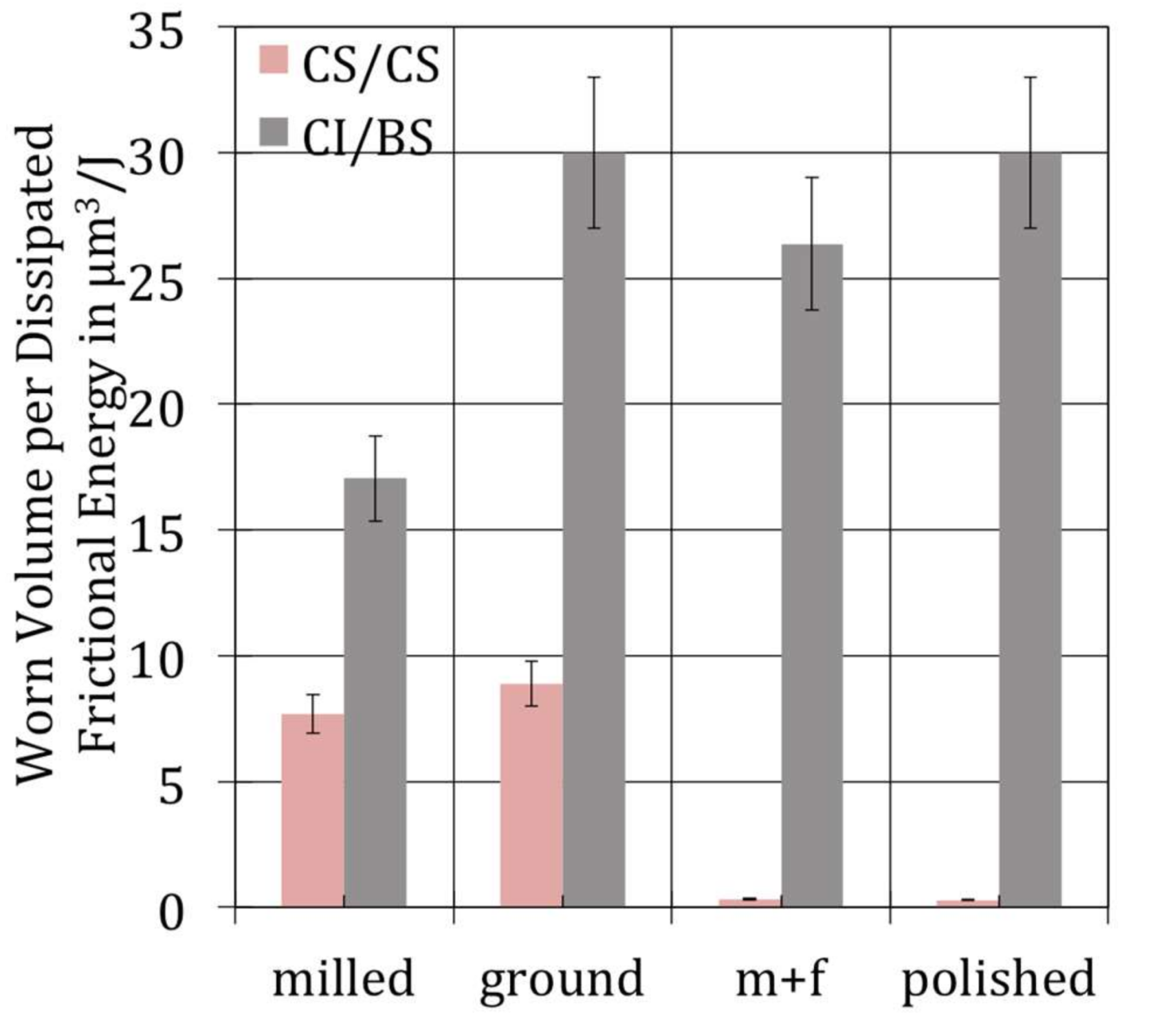
If one relates the worn volume WV to the dissipated frictional energy Ed accumulated over 2 × 10⁶ sliding cycles, it also becomes clear that there is no clear tendency as to the topographies for tribocouples (Figure 3). In order to wear away a certain volume from the surfaces in contact the CS/CS tribocouples would need to dissipate distinctly more frictional energy compared to CI/BS. In a first approach, this can be seen as a much smaller capability of the latter to transform the introduced frictional energy into something that does not result in material loss.
By calculating an average linear wear rate in nm/h from the volumetric numbers of [28,29] by simple geometrical equations, it becomes clear that for all tribocouples, the counter bodies (CB) show bigger numbers than the base bodies (BB) (Table 2). This can be explained by the fact that the contact area of the counter body is about 10 times smaller than that of the base body and that it is always in contact. Surprisingly, the 100Cr6 wears more than the softer flame hardened cast iron. Nonetheless, all values are in the sub-mild (1000 nm/h > W > 10 nm/h) or the ultra-mild (W < 10 nm/h) wear regime. In summary the removal of material in terms of µm3/J is by far more pronounced for the CI/BS-couples compared to CS/CS. In terms of nm/h, the counter bodies would wear about twenty- to eightyfold faster than the base bodies.
3.2. Wear Appearances
3.2.1. Carburized Steel 18CrNiMo7-6 vs. Carburized Steel 18CrNiMo7-6
Figure 4 shows the surfaces of the carburized steel base bodies before and after wear as well as the polished counter bodies after wear. This should demonstrate the influence of the initial surface topography on surface alterations during sliding wear.
Base Bodies. The milled and the ground sample show a flattening of the summits, which leads to an increase of the real contact area [21]. The polished surface demonstrated an opposite behaviour with grooves bring about a roughening of the contact. The influence of an optimized surface topography during manufacturing can be seen by comparing the milled with the milled + finished surfaces. While the summits of the milled surface were worn during sliding, any reduction of the milling marks was already achieved by the finishing before wear. As a result, such surface shows only minor alterations and no measurable wear loss of the base body (Table 2). The SEM analyses of the wear tracks reveal a smooth appearance with occasional grooves and some small pits, mostly in the contact zones of the counter bodies [21]. Thus microploughing (a submechanism of abrasion) and indentation (a submechanism of surface fatigue with predominantly plastic interactions) could be presumed to be the primary acting submechanisms [31].
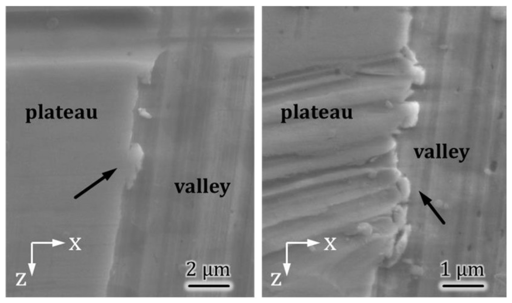
The opposite behavior of the ground and the milled tribocouples with regard to the wear of the counter and the base bodies, respectively, could be influenced by the orientation of the machining marks of the base bodies. The grinding marks of the ground base body run parallel to the sliding direction, probably allowing the summits to plough into the counter body, therefore, facilitating microploughing as well [31]. In the milled case, the machining marks are oriented perpendicular to the sliding direction. The stresses during sliding give rise to plastic deformation at the summits of the milled topography, consequently causing material to be pushed off the plateau (Figure 5).
Counter Bodies. Figure 6 illustrates the macroscopic changes of the contact areas of the counter bodies. These appear smooth with some grooves, which are most pronounced in the contact area of the counter body run against the polished surface. Microscopically, all contact areas look quite similar, showing some grooves and small pits, which point towards microcutting and/or microploughing (submechanisms of abrasion) as well as indentation (submechanism of surface fatigue).
3.2.2. Flame-Hardened Cast Iron EN HJS-HB265 vs. 100Cr6
Base Bodies. Figure 7 shows the surfaces of the flame-hardened cast iron bodies before and after wear as well as the polished 100Cr6 counter bodies after wear. From [28] we know that polished and ground surfaces showed a distinct run-in behaviour with regard to friction. This was explanation by the relatively smooth surfaces leading to a more distinct activation of the graphite nodules forming lubricating third bodies.
Thus, at a higher magnification the ground (Figure 8b) and polished (Figure 8d) surfaces appear only slightly plastically deformed with some pits, while the milled (Figure 8a) and the milled + finished (Figure 8c) samples show patches of former debris sticking rigidly to the surfaces. These patches consist mainly of P, Ca, S, and Zn and are known to be usual constituent of such cast irons. They are also found on the ground and polished surfaces, even though to a smaller extent [31]. The formation of such patchy third bodies could already originate from machining debris. For the milled and milled + finished samples microcracks were observed in the vicinity of graphite nodules (Figure 9). Such appearances also called metal sheaths around graphite nodules are known to be generated by machining [32]. Under tribological stresses such sheaths would be torn off and can result in the formation of larger and shallow particles that form those patches (Figure 8).
If such µm-large wear particles are pushed out of the contact zone they should give rise to wear by destroying any existing tribomaterial.
Counter Body. The worn surfaces of the counter bodies are shown in Figure 10. Again, all surfaces appear quite similar. At higher magnification it is evident that the wear tracks of the counter bodies are characterized by shallow grooves, small pits, and patches sticking to the surfaces. The contact areas sporadically show microcracks. These as well as the patches are most evident in the wear track of the counter body (Figure 10b) from the ground sample, followed by the counter body tested against the milled sample (Figure 10a). These appearances point towards microcutting, microploughing, and indentation.
4. Discussion
On the basis of the early investigations of the last century, friction, wear, and lubrication were seen as interconnected parts of an area named tribology in 1966. Most importantly it became clear that any tribological property is not just related to a certain material but it is connected to the entire tribological system consisting of base body, counter body, interfacial medium, and environment. This specific structure leads to certain friction and wear mechanisms (Figure 11) [33,34,35].
We distinguish between four main wear mechanisms: “Abrasion”, “Adhesion”, “Surface Fatigue” and “Tribochemical Reactions”, which are related to and can be defined by certain wear appearances. The alterations of the surfaces as to topography, chemistry, and microstructure as well as changes of the interfacial and surrounding media led to the further definition of so-called sub-mechanisms. This somewhat rough scheme (and even though not all sub-mechanisms are known or have yet been sufficiently investigated) has been proven to allow for targeted countermeasures [36]. Table 3 sums about up the current state of sub-mechanisms known to the authors.
It also has been shown by [35] and others that “Adhesion” might lead to wear rates that are nine or more orders of magnitude larger than those caused by “Tribochemical Reactions”. At the desired very small wear rates in the range of less than, e.g., <10 nm/h one would in general expect sub-mechanisms of “Tribochemical Reactions” and “Surface Fatigue”. The authors exemplified that a combination of “Mechanical Mixing” and “Indentation” may lead to relatively small wear rates [36,37]. This is the more pronounced the better the mechanically mixed layer (also called tribomaterial, Figure 12) at the surface is sufficiently supported by the subsurface microstructure (strain gradient, Figure 12) [18]. Another prerequisite is that such layer must not be overloaded by too large contact stresses [26]. Thus if “Indentation” as well as frictional shear forces trigger “Mechanical Mixing” and, therefore, generate tribomaterial and nano-size wear particles the total wear rates might become very small and even reach the so-called ultra-mild wear regime [26,38,39].
In order to properly analyze such near- or sub-surface structures one has to distinguish between either amorphous, nanocrystalline and/or chaotic surface layers and the underlying strain gradient, which is generated by the accumulation of cyclic plastic strains [17,18]. In contrast to this, the tribomaterial appears like a shear band [19], which is caused by monotonic stresses and strains similar, but not equal, to what is known from severe plastic deformation [45] (Figure 12). However, despite the intensive research of the last 70 years any direct or even quantitative relation to the so-called elementary processes like, e.g., the generation of lattice defects is still missing.
The presented gross numbers of material loss as well as accumulated dissipated frictional energy (Table 2) in combination with the wear appearances imply that the pathways of dissipation into wear can obviously be quite different for sub-mild or ultra-mild wear rates under boundary lubrication. Thus, the results should be discussed on the basis of the alteration of subsurface microstructures inside the tribomaterial and the strain gradient. In order to achieve this, the incipient state before wear is exemplary compared to that after wear.
4.1. Carburized Steel 18CrNiMo7-6 vs. Carburized Steel 18CrNiMo7-6
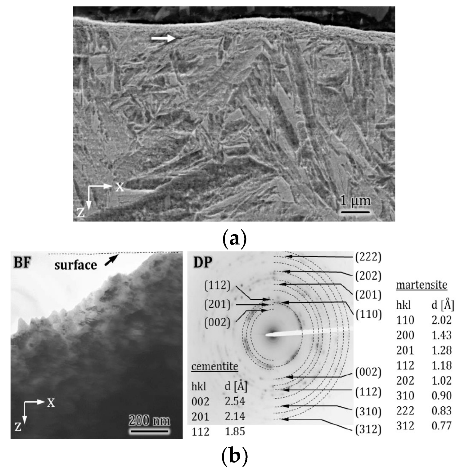
Cross-sections of the milled base body before wear is shown in Figure 13. The uppermost structure-less layer (Figure 13a) can be attributed to the secondary shear zone generated by machining and shows a nanocrystalline martensitic structure (Figure 13b) with cementite precipitates. It is important to notice that before machining no such precipitates were found within the microcrystalline martensite. Thus, some heat generation followed by self-tempering must have taken place during milling.
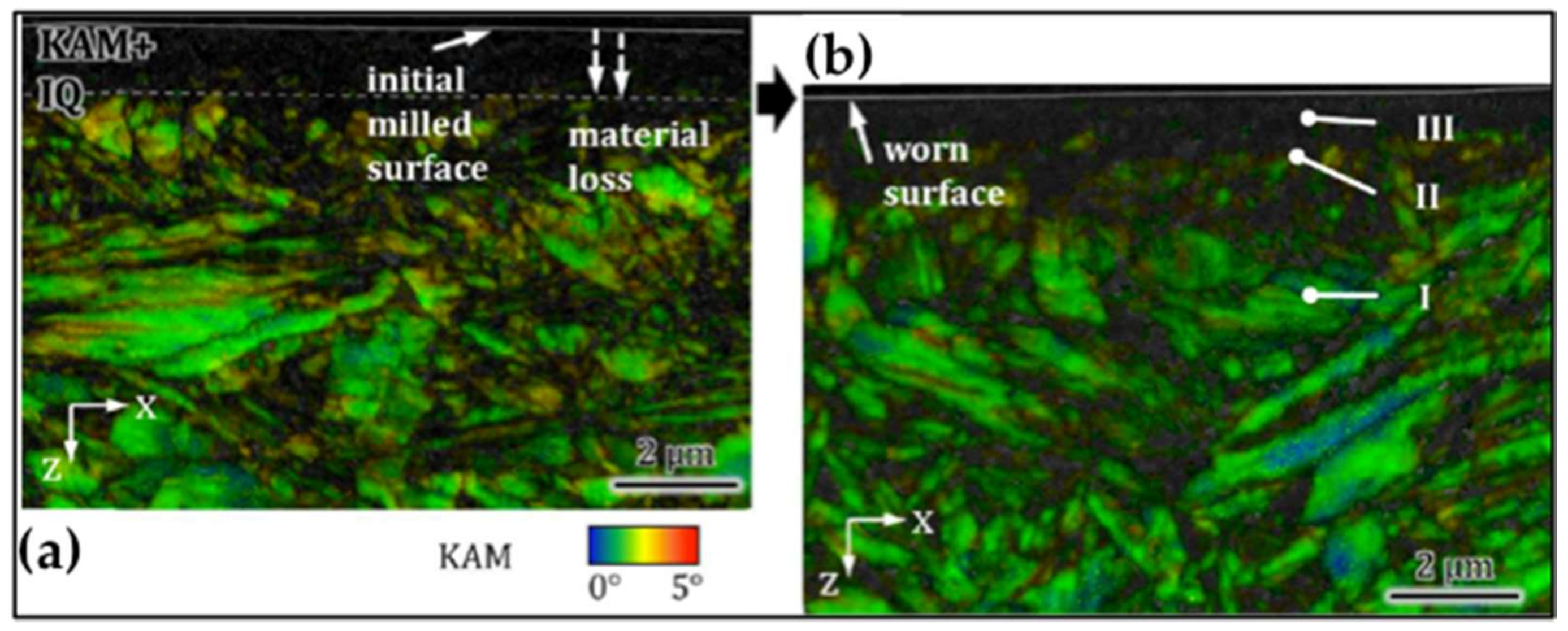
The KAM images (Figure 14) of the unworn (Figure 14a) and worn (Figure 14b) state appear similar with a highly deformed layer at the surface, which by EBSD appears just black and shows so called “no-counts”. This method cannot resolve severely deformed microstructures. Nonetheless, inside the highly deformed surface layer some small and less deformed areas can be seen. These are fragments of the former microcrystalline martensite plates.
While the severely deformed layer of Figure 14a could be related to machining, the one after wear is about 300 nm deeper and must, at least in parts, have been generated by tribological stresses. TEM bright field images and corresponding electron diffraction patterns at positions I, II, and III of figure 14b illustrate the microstructural gradient of the subsurface zone after wear (Figure 15).
Position I (Figure 15a) displays the bulk microstructure structure with the typical microcrystalline martensitic appearance. At position II (Figure 15b) the diffraction pattern slightly appears as rings pointing towards an increasing defect density as well as grain refinement. Towards the surface the microcrystalline structure vanishes completely by further grain refinement down to sizes below 100 nm at position III (Figure 15c).
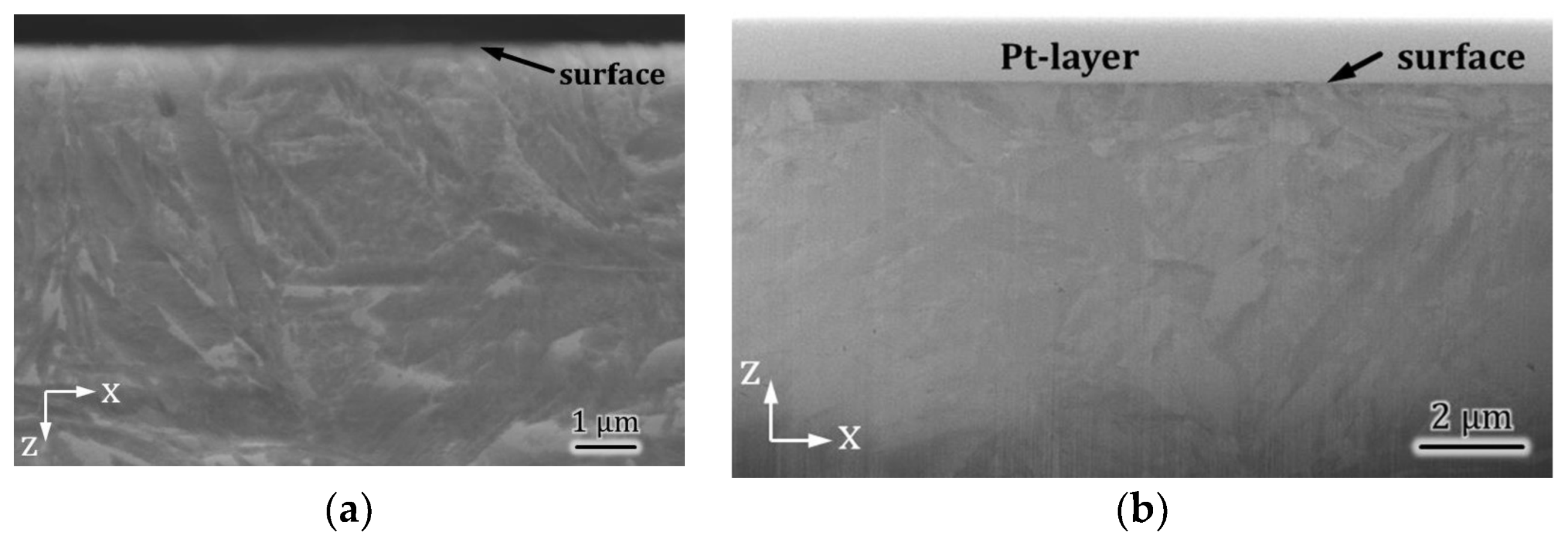
The polished counter body depicts a microcrystalline martensite up to the surface (Figure 16a) before wear testing while the FIB cross-section after being tested against the milled sample a marginal lattice distortion of the near-surface zone is hardly observable (Figure 16b).
At first glance, such divergent findings for the base and counter bodies as to the structure of the subsurface zones look surprising, because the wear depth of the latter is about 30 times larger. By this difference and the fact that the contact area is 10 times smaller one would expect much more frictional energy being somehow stored inside the subsurface zone of the counter body. However, obviously, this is not the case. It appears, therefore, interesting to compare these findings with a system that showed about the same frictional behaviour but did not wear to such extent; the milled + finished vs. polished tribocouple.
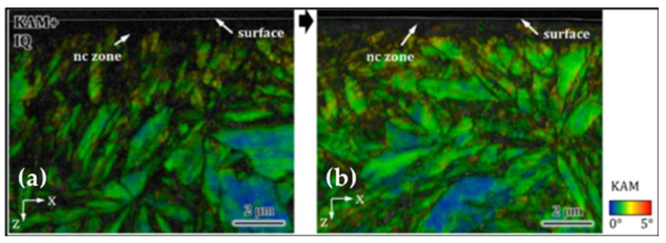
For the milled + finished base body the wear volume was not detectable, because the changes in topography were at the resolution limit of the confocal white light microscope [29]. With respect to any microstructural alteration during the wear tests, it is evident that these were not detectable as well (Figure 17). The comparison of the milled + finished base body prior to (Figure 17a) and after (Figure 17b) wear testing reveals absolutely no significant changes.
For the polished counter body this is different. Before wear the surface’s microstructure was microcrystalline, while after wear a highly deformed layer could be observed revealing an ultrafine crystalline martensite (Figure 18).
Stickel did show that that wear by WV and by WL could neither be related to the coefficient of friction, nor to the gross accumulated frictional energy Ed in kJ, nor to the specific dissipated frictional energy per half cycle Es,d in W/mm2, which in his model was related to the real contact area of that half cycle [21]. However, it became clear that below a certain value of Es,d no wear was measurable. Since Es,d was never zero for the real contact area, the frictional energy must have been stored inside the microstructure by some elementary mechanisms (like, e.g., transformation into lattice defects). For the milled + finished base body there was no detectable alteration at all, but by the dissipated frictional energy of that couple the counter body could develop a strain gradient (represented in figure 18 by a mixture of green patches representing fragments of the former martensite plates surrounded by black no-counts representing nanocrystalline martensite) and a nanocrystalline surface layer (represented by the uppermost thin black zone of “no-counts”), while about 1 µm has been worn away. This could be understood as some sort of stabilization of tribomaterial inside the contact zone. In contrast Es,d of the counter body run against the milled surface was about 10 times larger. Here no tribomaterial could be stabilized and, even if it had been generated by dissipating frictional energy, it must have been worn off immediately. This should be elucidated in detail in the following paragraph.
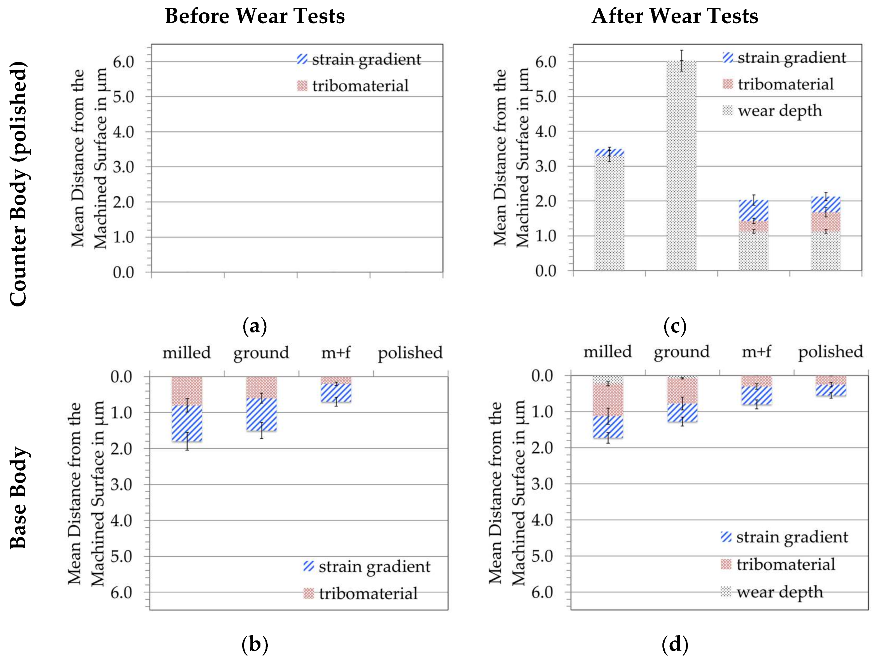
TEM offers a fair tool to investigate structures at high resolution in a certain position, but it does not allow for an overview along the wear track. Thus, and in order to gain such overview within one as well as over the different tribosystems investigated here the thickness of the strain gradients as well as those of the uppermost tribomaterial has been analysed by EBSD on all micrographs at hand. By the resolution of this analyses as well by the fact that the interfaces between base material and strain gradient and strain gradient and tribomaterial are not always sharply defined, such quantitative analysis bares some uncertainties. However, plotted in combination with the measured depth of the wear tracks it might help to understand obvious differences of the pathways of dissipation. Figure 19 shows the results of such analyses comparing the depth of the wear track and the thicknesses of strain gradient and tribomaterial in nm. The uncertainties as well as any local values scattering by position, roughness, and loading history are represented by the error bars. For better comparability all y-axes are plotted within the same range, while 0.00 always represents the surfaces after machining.
Due to the microcrystalline surface of the polished counter bodies, Figure 19a does not show any indications of a strain gradient or a nanocrystalline surface layer, while for the base bodies this is more pronounced depending on the specific machining procedure (Figure 19b). By milling the remaining microstructural alterations reach nearly two micrometres deep, while after polishing there are none at all. The base bodies show quite small average depths of the wear scars (Figure 19d). For the milled samples it is less than 300 nm, so that after wear the strain gradient as well as the nanocrystalline zone is about in range of depth of those before wear. At a first glimpse this appears to be in contrast to what we have shown before, but in fact it is not. The TEM figures are taken at certain positions of the wear tracks, while the analyses of Figure 19 are taken from several positions and represent a mean value and not a local one. This elucidates the fact that both methods EBSD and TEM have their possibilities and limitations in revealing, what is characteristic under a worn surface. This overlapping of regions is also true for the ground and the milled + finished base bodies. Thus, one cannot distinguish between what has been there before wear and what has been generated by the dissipation of frictional energy during the wear tests. The only hint towards a possible difference for the milled samples lies in the fact that after machining the nc-layer did show cementite precipitates, which were not found before machining. Nonetheless, for the other machining processes there were no such precipitates and for the ground and milled + finished base bodies such differences cannot be shown at all. The only unequivocal alteration resulting from tribological stresses can be seen for the polished counter body. It depicts a distinct strain gradient and tribomaterial after wear that has not been there before. This in general can be seen as the capability of microcrystalline martensite to dissipated frictional energy by transforming it into the generation of lattice defects and a stable tribomaterial without any measurable wear loss. Stickel showed on the basis of his Es,d-model that for these cases (milled + finished, polished) the base bodies’ materials dissipate less than 100 W/mm2 per half-cycle of the stroke.
Clearly, the counter bodies do not dissipate by the same pathways. All of them show a distinct larger wear depth after two million cycles (Figure 19c). As mentioned before Es,d is about 10 times larger for the counter bodies because of the smaller real contact area and they are always in contact. However, because the Es,d-model does not regard the time in contact, its influence cannot be quantified. Nevertheless, for the relatively small Es,d-values of the milled + finished and the polished couples the counter bodies could build a strain gradient and tribomaterial meaning that parts of the dissipated energy could be stored without wear. For the milled tribocouple a small strain gradient can be seen, but no tribomaterial, while for the ground one, obviously, the Es,d was so large that it was transformed into direct wear loss. It is known from former work that too small tribological stresses do not generate stable tribomaterial, while too large stresses remove it immediately [26]. Thus, maybe some tribomaterial formed on the counter body run against the milled and the ground base bodies, but it wore off immediately.
According to the third-bodies approach of [47,48] the accommodation of the velocity gradient of the interfacial medium can be based on different accommodation modes like elastic deformation, breaking, shearing, and rolling. Combining the third-bodies approach with our strain gradient-tribomaterial model (Figure 12) we would sort the accommodation modes as follows:
- Due to the fact that we found no cracks with this tribocouple the breaking mode can be ruled out.
- From [19] we know that shear bands are characterised by extreme grain refinement which would take up the shearing mode, while.
- According to [50] nanocrystalline metals deform under shear by rotation of grains comprising the rotation mode.
Finally, we can accept the nanocrystals inside the tribomaterial as detached from the strain gradient, but not yet ejected from the tribosystem. From [22] we know that not any wear particle that detaches must also be ejected but might remain in the contact zone and built so-called third-body particles. In our model this would be the tribomaterial on top of the strain gradient. Thus, the question is not whether a wear particle detaches form the strain gradient into the tribomaterial, but whether it is ejected from the latter. Now the tribomaterial under boundary lubrication is a metallo-organic nanostructured composite with unknown load carrying capacity and viscosity, but it has been shown that it only can hinder wear losses within a certain loading range [26]. If the tribological stresses are too large, the tribomaterial might be generated, but it is immediately squeezed out of the contact zone. Thus, inside such optimal tribological stress field the number of particles ejected balances the numbers of particles detached and, therefore, allow for a stable tribomaterial and an ultra-mild wear rate. If such particles just detach but are not ejected the wear rate is close to zero.
In our tribosystems one can apply such a modelled view in a way that wear particles detach from the top of the strain gradient into the tribomaterial and by rolling might even act as solid lubricant. The high defect density inside the strain gradient as well as the generation of defect free domains could define the size of such wear particles as long as no cracks are generated inside the strain gradient [18]. Additionally, the shearing of the surface is hindered by, e.g., grain boundaries and generates so-called overfolds that resemble ultrafine- and nanocrystalline shear bands [51,52,53]. If the tribological loading, e.g., defined by different Es,d for body and counter body is under a certain value (e.g., called Es,d,0) the defects are just accumulated so that wear particles detach, but are mostly not ejected staying inside the tribomaterial as it is for the milled + finished and the polished tribocouples. Here, Es,d,0 of the base body would be about 100 W/mm2. For the counter body, it would be about 1.000 W/mm2 for the roughly 10 times smaller real contact area. For Es,d > Es,d,0, particles are generated and ejected so that measurable wear takes place. Nonetheless, Es,d is stored by lattice defects allowing for the generation of a strain gradient and tribomaterial and leading to a small wear rate. This could be true for the milled tribocouple, in which the base body can mostly store the frictional energy, while the counter body cannot. However, in contrast, it could also be that, by the already deformed subsurface material of the base body by machining, no further dissipation is possible and the counter body dissipates it all. Due to the fact that we do not know the fraction of dissipation and storage such explanation must remain hypothetical. Nonetheless, theoretically one could derive that above a critical value Es,d,c the material is overloaded, generates an immediate shear band (maybe even without a strain gradient for too little numbers of cycles), which is squeezed out of the contact zone. In that case, we find neither a strain gradient nor tribomaterial like for the counter body of the ground tribocouple, which also showed the largest Es,d of 3500 W/mm2.
4.2. Conclusions of Carburized Steel 18CrNiMo7-6 vs. Carburized Steel 18CrNiMo7-6
Qualitatively there appears to be a relation but it is not unquestionable. We do not know how much frictional energy can be stored as well as the interdependencies of the different pathways based on the loading history by machining and tribological loading. We also do not know the fraction between body and counter body as well as the influence of the localization as to location and time. Finally, the elementary mechanisms of particle detachment as well as those of particle ejection are still unknown not to mention their dissipative character. Thus, beside such qualitative description of the relations between the topography and the pathways of the dissipation of frictional energy any fully conclusive one cannot be given.
4.3. Flame-Hardened Cast Iron EN HJS-HB265 vs. 100Cr6 (CI/BS)
Now the question appears to be whether at least the descriptions given above can be applied to a tribosystem, which according to [28] shows a different friction and wear behaviour under similar tribological stresses. The volumetric and the linear wear rates as well as the behaviour of the base and counter bodies could not be related to any machining procedure (Table 2). Nonetheless, the base bodies showed ultra-mild and the counter bodies sub-mild (but now up to 80 times larger) wear depths.
By comparing the near- and subsurface zones of the base bodies after the wear tests as to possible strain gradients or tribomaterials, not even a qualitative ranking related to the surface topographies is possible (Figure 20).
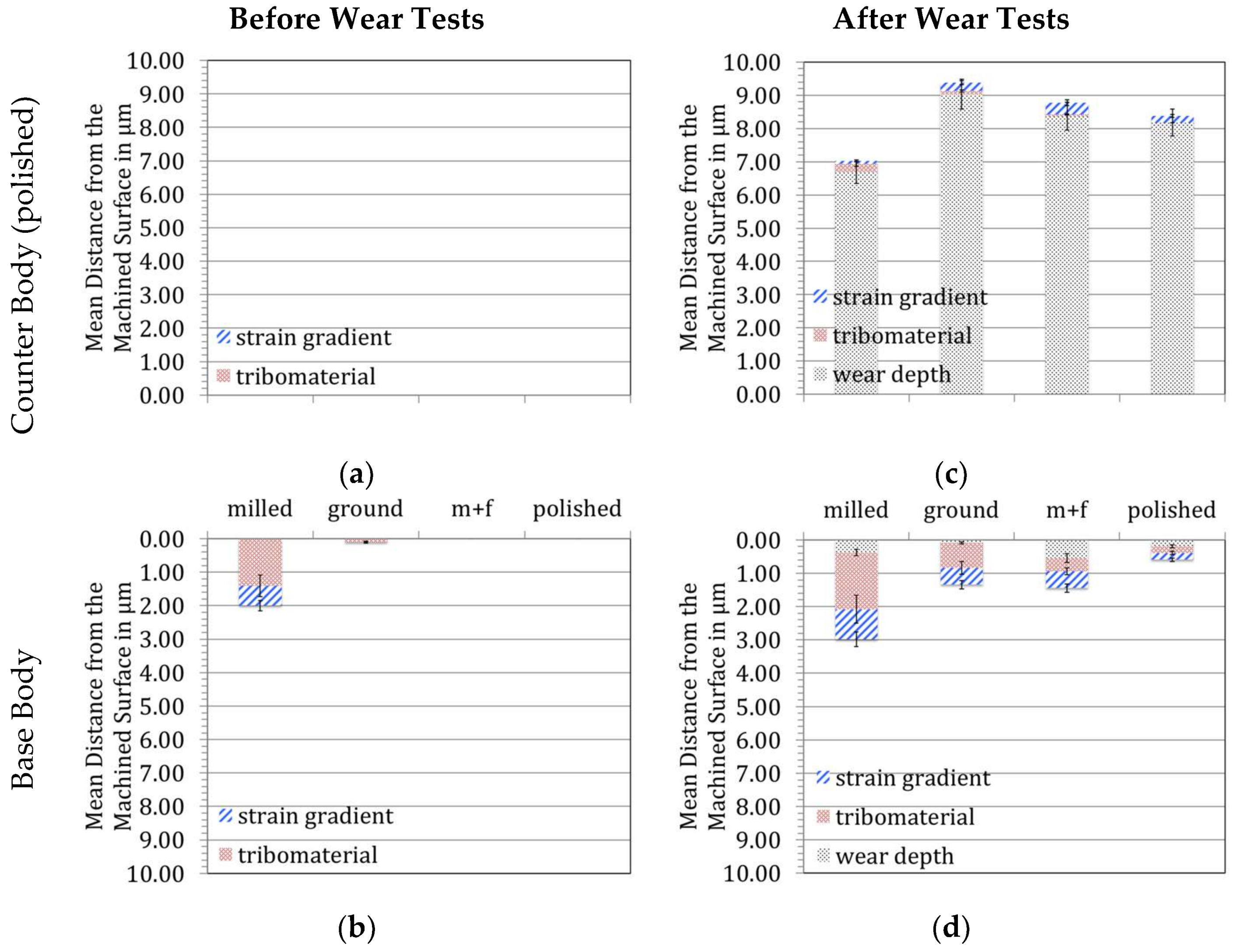
This can be further elucidated by plotting the depth of the wear scars in relation to the thicknesses of the strain gradients and tribomaterials on the basis of all EBSD and TEM micrographs at hand (Figure 21). Again, this plot regards the scatter between different positions of wear tracks as well as the uncertainties of the methods. For better comparability, all y-axes are plotted within the same range, while 0.00 always represents the surfaces after machining.
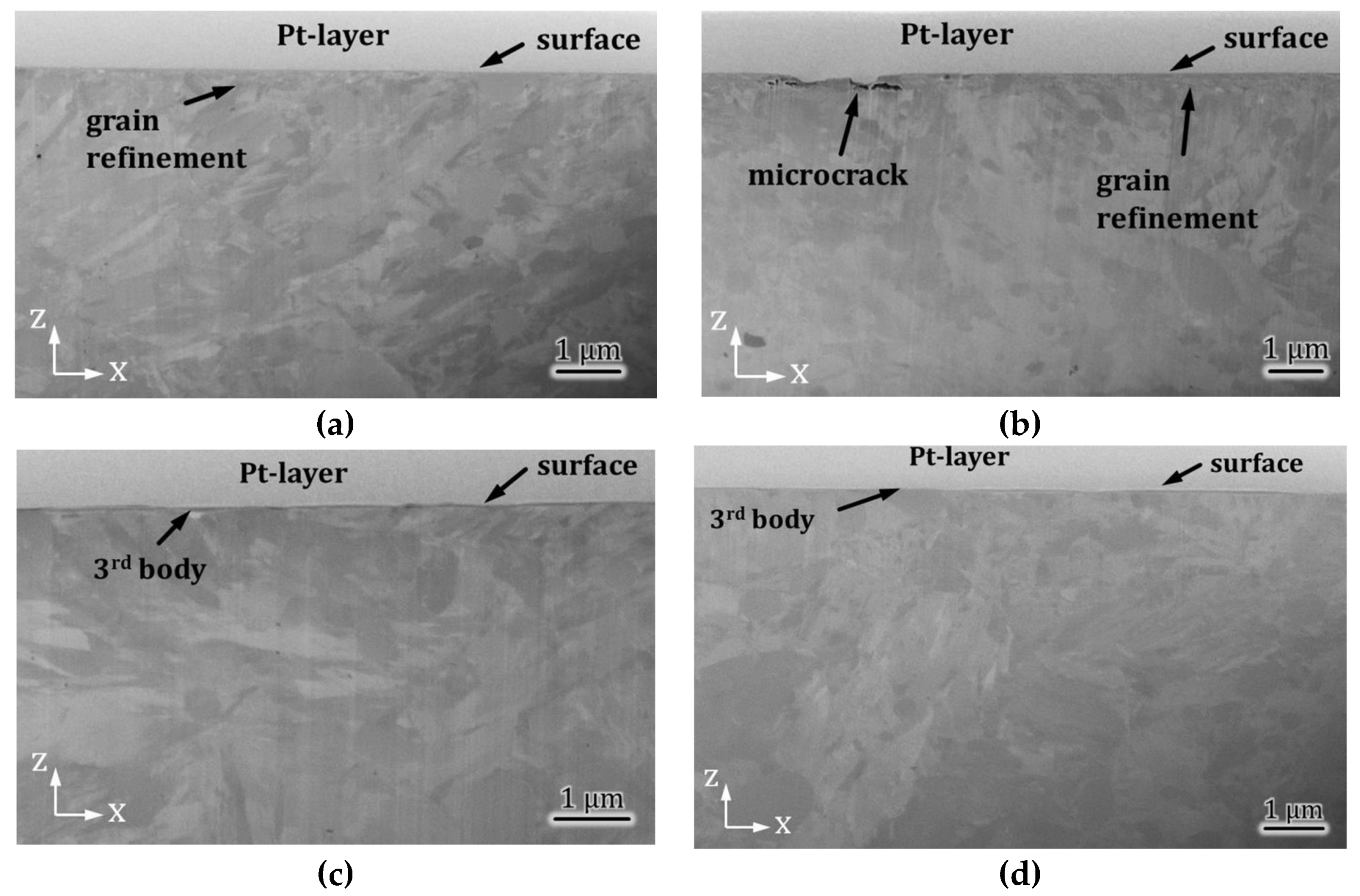
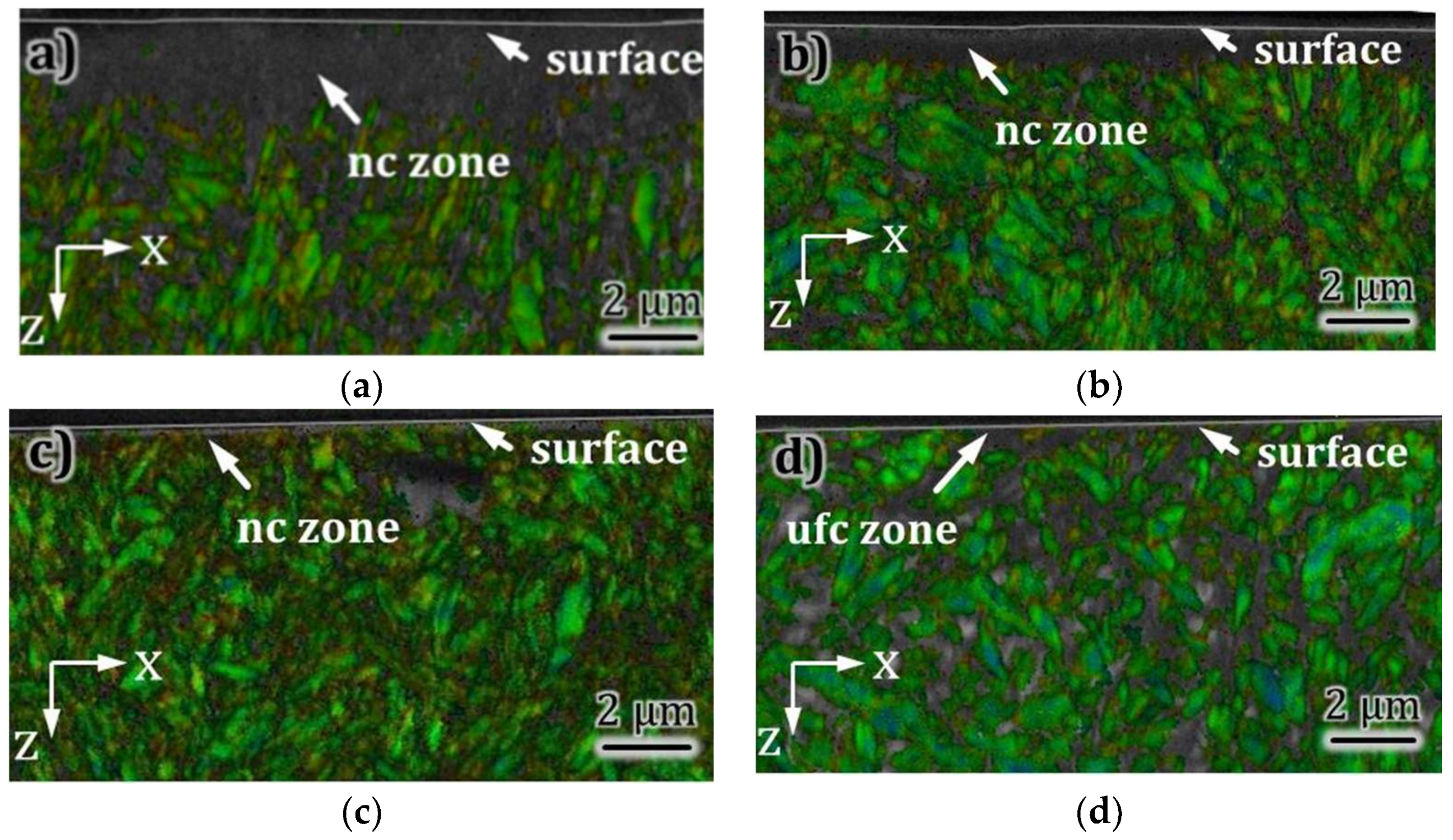
Obviously, the transformation of the frictional energy into strain gradient, tribomaterial, and wear follows similar paths but to absolutely different spreading, when compared to the CS/CS tribocouples in Figure 19. The polished counter bodies of commercial 100Cr6 bearing balls did neither show a strain gradient nor some nanocrystalline tribomaterial (Figure 21a). The cast iron base bodies displayed such alterations by machining, which were most pronounced for the milled surface (Figure 21b). The ground one showed only a very thin nanocrystalline layer, but no discernible strain gradient. The milled + finished as well as the polished surface in general did not reveal any alteration near the uppermost surface by machining [31]. Nevertheless, after wear all base bodies displayed marked microstructural features that must have been generated by tribological stresses (Figure 21d). The higher efficiency of the dissipated frictional energy to generate material loss has already been shown in Figure 3 for the CI/BS wear tests. From the volumetric wear rates (Table 2) the counter bodies wore either equally or more than the base bodies, while for the linear wear rates the depth of the wear tracks are much bigger for the counter bodies and two- to fourfold bigger than for the counter bodies of the CS/CS wear tests. Thus, the most distinct difference to the CS/CS couples is brought about by the behaviour of the BS counter bodies, which wore much more than the even softer CI base bodies. Surprisingly they also did display neither any distinct generation of a strain gradient nor of a tribomaterial (Figure 21c). FIB cross-sections of the counter bodies of the milled + finished and the polished couples indicate only very minor alterations (Figure 22c,d), whereas the counter bodies of the milled and the ground ones reveal some grain refinement (Figure 22a,b). Most obviously, the cross-section of the counter body run against the ground body bares microcracks parallel to the surface.
On the basis of this and the measured wear rates it appears reasonable to hypothesize that the base bodies can somehow transform the frictional energy into deformation within the strain gradient and the tribomaterial, while the counter bodies transform it more or less directly into material loss. The wear appearances on the base bodies allow for the assumption that beside microploughing (shallow grooves in Figure 10b–d), indentation by rotating wear debris (pits in Figure 10a,d) might have been the prominent submechanisms. At least this would explain the sub-mild wear rates, while again the counter body for its about 10 times smaller real contact area dissipates and transforms assumingly 10 times more frictional energy. Due to the fact that for the counter bodies we find nearly no appearances of deformation below the worn surface, we must accept that any deformation zone generated is immediately sheared out of the contact. Thus the relatively large Es,d values [21] of the CI/BS tribocouples do not allow for a stable tribomaterial on the counter bodies surfaces. The combination milled vs. polished with the smallest linear wear rates (Table 2) as well as the smallest ratio of Wv/Ed (Figure 3) show the most distinct strain gradient and tribomaterial after the wear test. Again, it appears that the capability to transform frictional energy into certain lattice defects, which store it, looks beneficial for the tribological behaviour. Unfortunately, it also becomes clear that there is absolutely no simple relation between the topography, the dissipated frictional energy and the wear loss.
4.4. Conclusions of Flame-Hardened Cast Iron vs. Ball Bearing Steel 100Cr6
For this tribocouple a description of pathways appears possible, but a conclusive relation between topography and wear could once more not be found. Again, the fraction of frictional energy dissipated as well as its pathways and effectiveness of generating wear are not quantifiable. The martensitic ball bearing steel 100Cr6 displays a very limited capability to store the dissipated frictional energy. One reason could be the missing of compressive residual stresses. As for the other tribosystem investigated the elementary mechanisms of particle detachment as well as those of particle ejection remain unknown.
5. Limitations
There are some aspects that cannot be elucidated here due to the chosen experimental approach, the structure of the tribosystem and the lack of data.
If the metal sheaths (Figure 9) generated by machining tear off the surfaces any existing tribomaterial should be worn away by one stroke and a new run-in process would start. The given tribosystem and in-situ analyses of normal and friction forces obviously did not allow for the discrimination of such single incidents during 2 × 10⁶ cycles.
The distinctly larger wear depths of the 100Cr6 counter bodies, e.g., compared to those of the carburized 17CrNiMo7-6 ones, could be linked to the missing of any compressive residual stresses within the bearing balls. The positive effect of such compressive residual stresses is known but the question emerges as to whether they have a positive effect by lowering any tensile contact stresses, or by stabilizing the strain gradient for a better support of the tribomaterial, or both.
This investigation did not discuss the influence of the load carrying capacity of loose (detached but not ejected) wear particles, because we did not carry out a full statistical analysis of the few particles and their agglomerates that were extracted from the lubricant.
6. Conclusions and Outlook
Martensitic materials can dissipate frictional energy and transform it into strain gradients and tribomaterials without wearing immediately. Thus, tribomaterial can be built up and kept stable up to a certain amount of specific dissipated frictional energy. The pathways of dissipation and transformation of frictional energy can be analysed and described but they cannot be conclusively related to each other or even quantified.
TEM analyses are necessary but insufficient for their distinct localisation of characterization. EBSD as well as other methods must be included on and below the surfaces in order to gain information about adequate contact areas and loaded microstructural volumes.
Both base bodies and counter bodies must be analysed in order to be able to gain sufficient information about the characteristics of a tribosystem.
The fraction of dissipation and transformation between both bodies is still unknown. Volumetric and linear wear rates might lead to different conclusions about this.
It appears that there might be critical values of dissipated frictional energy, which generates wear particles, but they stay inside the tribomaterial and are not ejected.
Nonetheless, by means of an appropriate model for the calculation of the real contact area and a sound analysis of the subsurface microstructural gradients and their alterations, one does gain information on the main acting submechanisms. This renders information on how to optimize the topography and the materials microstructures within a certain tribosystem.
Acknowledgments
The authors are in debt to D. Biermann and S. Goeken of TU-Dortmund, Germany as well as to W. Theisen and K. Geenen of Ruhr-University Bochum, Germany. Essential parts of this work have been sponsored by the Mercator Foundation, Essen under contract MERCURPR-2011-0002.
Author Contributions
Priska Stemmer developed and performed the complex preparation of ferromagnetic specimens for high-resolution microscopy, the light-, scanning- and transmission-electron microscopy as well as their complete analyses; Alfons Fischer wrote the paper.
Conflicts of Interest
The authors declare no conflicts of interest.
References
- Fleischer, G. Energy method of wear computation. Schmier 1973, 4, 269–274. [Google Scholar]
- Uetz, H.; Foehl, J. Wear as an energy transformative process. Metaux. Corros. Ind. 1979, 55, 340–350. [Google Scholar]
- Heilmann, P.; Rigney, D.A. An energy-based model of friction and its application to coated systems. Wear 1981, 72, 195–217. [Google Scholar] [CrossRef]
- Fouvry, S.; Kapsa, P.; Zahouani, H.; Vincent, L. Wear analysis in fretting of hard coatings through a dissipated energy concept. Wear 1997, 203–204, 393–403. [Google Scholar] [CrossRef]
- Fouvry, S.; Paulin, C.; Liskiewicz, T. Application of an energy wear approach to quantify fretting contact durability: Introduction of a wear energy capacity concept. Tribol. Int. 2007, 40, 1428–1440. [Google Scholar] [CrossRef]
- Abdel-Aal, H.A. Influence of frictional energy dissipation on wear regime transition in dry tribo-systems. Int. J. Mater. Prod. Technol. 2010, 38, 78–92. [Google Scholar]
- Rymuza, Z. Energy concept of the coefficient of friction. Wear 1996, 199, 187–196. [Google Scholar] [CrossRef]
- Huq, M.Z.; Celis, J.P. Expressing wear rate in sliding contacts based on dissipated energy. Wear 2002, 252, 375–383. [Google Scholar] [CrossRef]
- Fouvry, S.; Liskiewicz, T.; Kapsa, P.; Hannel, S.; Sauger, E. An energy description of wear mechanisms and its applications to oscillating sliding contacts. Wear 2003, 255, 287–298. [Google Scholar] [CrossRef]
- De Moerlooze, K.; Al-Bender, F.; Van Brussel, H. A novel energy-based generic wear model at the asperity level. Wear 2011, 270, 760–770. [Google Scholar] [CrossRef]
- Hanke, S.; Samerski, I.; Schöfer, J.; Fischer, A. The role of wear particles under multidirectional sliding wear. Wear 2009, 267, 1319–1324. [Google Scholar] [CrossRef]
- Shakhvorostov, D.; Pöhlmann, K.; Scherge, M. An energetic approach to friction, wear and temperature. Wear 2004, 257, 124–130. [Google Scholar] [CrossRef]
- Gane, N.; Skinner, J. The generation of dislocations in metals under a sliding contact and the dissipation of frictional energy. Wear 1973, 25, 381–384. [Google Scholar] [CrossRef]
- Jost, N.; Schmidt, I. Friction-induced martensitic transformation in austenitic manganese steels. Wear 1986, 111, 377–389. [Google Scholar] [CrossRef]
- Oila, A.; Bull, S.J. Phase transformations associated with micropitting in rolling/sliding contacts. J. Mater. Sci. 2005, 40, 4767–4774. [Google Scholar] [CrossRef]
- Cao, S.; Sarasin, F.; Cantoni, M.; Mischler, S. Effect of surface films on tribologically induced metallurgical transformations of steel in oil lubricated contacts. Wear 2016, 368–369, 75–83. [Google Scholar] [CrossRef]
- Saleski, W.J.; Fisher, R.M.; Ritchie, R.O.; Thomas, G. The Nature and Origin of Sliding Wear Debris from Steels. Available online: https://cloudfront.escholarship.org/dist/prd/content/qt7t1779pp/qt7t1779pp.pdf (accessed on 3 April 2018).
- Fischer, A.; Weiss, S.; Wimmer, M.A. The tribological difference between biomedical steels and CoCrMo-alloys. J. Mech. Behav. Biomed. Mater. 2012, 1, 50–62. [Google Scholar] [CrossRef] [PubMed]
- Rainforth, W.M.; Stevens, R.; Nutting, J. Deformation structures induced by sliding contact. Philos. Mag. A 1992, 66, 621–641. [Google Scholar] [CrossRef]
- Büscher, R.; Fischer, A. The pathways of dynamic recrystallization in all-metal hip joints. Wear 2005, 259, 887–897. [Google Scholar] [CrossRef]
- Stickel, D. The Influence of Surface Finish on the Localized Dissipation of Frictional Power at Ultra-Mild Wear. Ph.D. Thesis, University of Duisburg-Essen, Duisburg, Germany, 2015. [Google Scholar]
- Fillot, N.; Iordanoff, I.; Berthier, Y. Wear modeling and the third body concept. Wear 2007, 262, 949–957. [Google Scholar] [CrossRef]
- Johnson, K.L. Contact Mechanics; Cambridge University Press: Cambridge, UK, 1985; p. 425. [Google Scholar]
- Berns, H.; Theisen, W. Ferrous Materials: Steel and Cast Iron; Springer: Berlin, Germany, 2008. [Google Scholar]
- Goeke, S.; Biermann, D.; Stickel, D.; Stemmer, P.; Fischer, A.; Geenen, K.; Huth, S.; Theisen, W. Enhancing the surface integrity of tribologically stressed contacting surfaces by an adjusted surface topography. Procedia CIRP 2014, 13, 214–218. [Google Scholar] [CrossRef]
- Wimmer, M.A.; Laurent, M.P.; Mathew, M.T.; Nagelli, C.; Liao, Y.; Marks, L.D.; Jacobs, J.J.; Fischer, A. The effect of contact load on CoCrMo wear and the formation and retention of tribofilms. Wear 2015, 332–333, 643–649. [Google Scholar] [CrossRef] [PubMed]
- Bermúdez, M.D.; Iglesias, P.; Jiménez, A.E.; Martínez-Nicolás, G. Influence of sliding frequency on reciprocating wear of mold steel with different microstructures. Wear 2009, 267, 1784–1790. [Google Scholar] [CrossRef]
- Stickel, D.; Goeke, S.; Geenen, K.; Huth, S.; Theisen, W.; Biermann, D.; Fischer, A. Reciprocating sliding wear of case-hardened spheroidal cast iron against 100Cr6 under boundary lubrication. Proc. Inst. Mech. Eng. J. Eng. Tribol. 2015, 229, 1214–1226. [Google Scholar] [CrossRef]
- Stickel, D.; Fischer, A.; Bosman, R. Specific dissipated friction power distributions of machined carburized martensitic steel surfaces during running-in. Wear 2015, 330, 32–41. [Google Scholar] [CrossRef]
- Büscher, R. Gefügeumwandlungen und partikelbildung in künstlichen metall/metall-hüftgelenken. Ph.D. Thesis, Universität Duisburg-Essen, Düsseldorf, Germany, 2005. [Google Scholar]
- Stemmer, P. The divergent pathways and mechanisms of energy dissipation at the interfaces of martensitic tribocouples. Ph.D. Thesis, University of Duisburg-Essen, Duisburg, Germany, 2016. [Google Scholar]
- Dimkovski, Z.; Anderberg, C.; Rosén, B.G.; Ohlsson, R.; Thomas, T.R. Quantification of the cold worked material inside the deep honing grooves on cylinder liner surfaces and its effect on wear. Wear 2009, 267, 2235–2242. [Google Scholar] [CrossRef]
- Czichos, H.; Dowson, D. Tribology: A systems approach to the science and technology of friction, lubrication and wear. Tribol. Int. 1978, 11, 259–260. [Google Scholar] [CrossRef]
- Czichos, H. Overview and Classification. In Wear Mechanisms in Tribological Systems; Ehmann, K.F., Ed.; ASME: New Orleans, LA, USA, 1993; pp. 239–241. [Google Scholar]
- Zum Gahr, K.H. Microstructure and Wear of Materials; Elsevier: Amsterdam, The Netherlands, 1987. [Google Scholar]
- Fischer, A. Well-founded selection of materials for improved wear resistance. Wear 1996, 194, 238–245. [Google Scholar] [CrossRef]
- Sikorski, M.E. The adhesion of metals and factors that influence it. Wear 1964, 7, 144–162. [Google Scholar] [CrossRef]
- Quinn, T.F.J. Review of oxidational wear part ii: Recent developments and future trends in oxidational wear research. Tribol. Int. 1983, 16, 305–315. [Google Scholar] [CrossRef]
- Jahanmir, S.; Suh, N.P. Mechanics of subsurface void nucleation in delamination wear. Wear 1977, 44, 17–38. [Google Scholar] [CrossRef]
- Mischler, S.; Spiegel, A.; Stemp, M.; Landolt, D. Influence of passivity on the tribocorrosion of carbon steel in aqueous solutions. Wear 2001, 251, 1295–1307. [Google Scholar] [CrossRef]
- Wimmer, M.A.; Loos, J.; Heitkemper, M.; Fischer, A. The acting wear mechanisms on metal-on-metal hip joint bearings—In vitro results. Wear 2001, 250, 129–139. [Google Scholar] [CrossRef]
- Rigney, D.A.; Hammerberg, J.E. Mechanical mixing and the development of nanocrystalline material during the sliding of metals. In Proceedings of the TMS Fall Meeting, Colorado Springs, CO, USA, 1–4 November 1999; pp. 465–474. [Google Scholar]
- Wimmer, M.A.; Fischer, A.; Buscher, R.; Pourzal, R.; Sprecher, C.; Hauert, R.; Jacobs, J.J. Wear mechanisms in metal-on-metal bearings: The importance of tribochemical reaction layers. J. Orthop. Res. 2010, 28, 436–443. [Google Scholar] [CrossRef] [PubMed]
- Liao, Y.; Pourzal, R.; Wimmer, M.A.; Jacobs, J.J.; Fischer, A.; Marks, L.D. Graphitic tribological layers in metal-on-metal hip replacements. Science 2011, 334, 1687–1690. [Google Scholar] [CrossRef] [PubMed]
- Wu, S.D.; Wang, Z.G.; Jiang, C.B.; Li, G.Y.; Alexandrov, I.V.; Valiev, R.Z. Shear bands in cyclically deformed ultrafine grained copper processed by ecap. Mater. Sci. Eng. A 2004, 387–389, 560–564. [Google Scholar] [CrossRef]
- Schmaltz, G. Technische oberflächenkunde; feingestalt und eigenschaften von grenzflächen technischer körper, insbesondere der maschinenteile; Springer: Berlin, Germany, 1936. [Google Scholar]
- Godet, M. The third-body approach: A mechanical view of wear. Wear 1984, 100, 437–452. [Google Scholar] [CrossRef]
- Godet, M. Third-bodies in tribology. Wear 1990, 136, 29–45. [Google Scholar] [CrossRef]
- Glardon, R.; Chavez, S.; Finnie, I. Simuation of sliding wear by cyclic plastic deformation under combined stresses. J. Eng. Mater. Technol. Trans. ASME 1984, 106, 248–252. [Google Scholar] [CrossRef]
- Rigney, D.A. Transfer, mixing and associated chemical and mechanical processes during the sliding of ductile materials. Wear 2000, 245, 1–9. [Google Scholar] [CrossRef]
- Beckmann, N.; Romero, P.A.; Linsler, D.; Dienwiebel, M.; Stolz, U.; Moseler, M.; Gumbsch, P. Origins of folding instabilities on polycrystalline metal surfaces. Phys. Rev. Appl. 2014, 2, 064004. [Google Scholar] [CrossRef]
- De Beer, S.; Müser, M.H. Viewpoint: surface folds make tears and chips. Physics 2012, 5, 100. [Google Scholar] [CrossRef]
- Sundaram, N.K.; Guo, Y.; Chandrasekar, S. Mesoscale folding, instability, and disruption of laminar flow in metal surfaces. Phys. Rev. Lett. 2012, 109, 106001. [Google Scholar] [CrossRef] [PubMed]
Figure 1.
Microstructure and hardness profile of case hardened 18CrNiMo7-6 (Tribocouple CS/CS). The dashed area represents the scatter of the hardness profiles measured at different samples.
Figure 1.
Microstructure and hardness profile of case hardened 18CrNiMo7-6 (Tribocouple CS/CS). The dashed area represents the scatter of the hardness profiles measured at different samples.

Figure 2.
Microstructure and hardness profile of (a) flame hardened EN GJS-HB265 (Tribocouple CI/BS) and (b) the standard ball bearing steel 100Cr6. The dashed area within (a) represents the scatter of the hardness profiles measured at different samples.
Figure 2.
Microstructure and hardness profile of (a) flame hardened EN GJS-HB265 (Tribocouple CI/BS) and (b) the standard ball bearing steel 100Cr6. The dashed area within (a) represents the scatter of the hardness profiles measured at different samples.

Figure 3.
The ratio of the worn volume WV and the accumulated frictional energy Ed after 2 × 10⁶ sliding cycles (≈24 km wear path).
Figure 3.
The ratio of the worn volume WV and the accumulated frictional energy Ed after 2 × 10⁶ sliding cycles (≈24 km wear path).

Figure 4.
Surface appearances after machining and after CS/CS wear tests. Direction x is parallel to the relative velocity.
Figure 4.
Surface appearances after machining and after CS/CS wear tests. Direction x is parallel to the relative velocity.
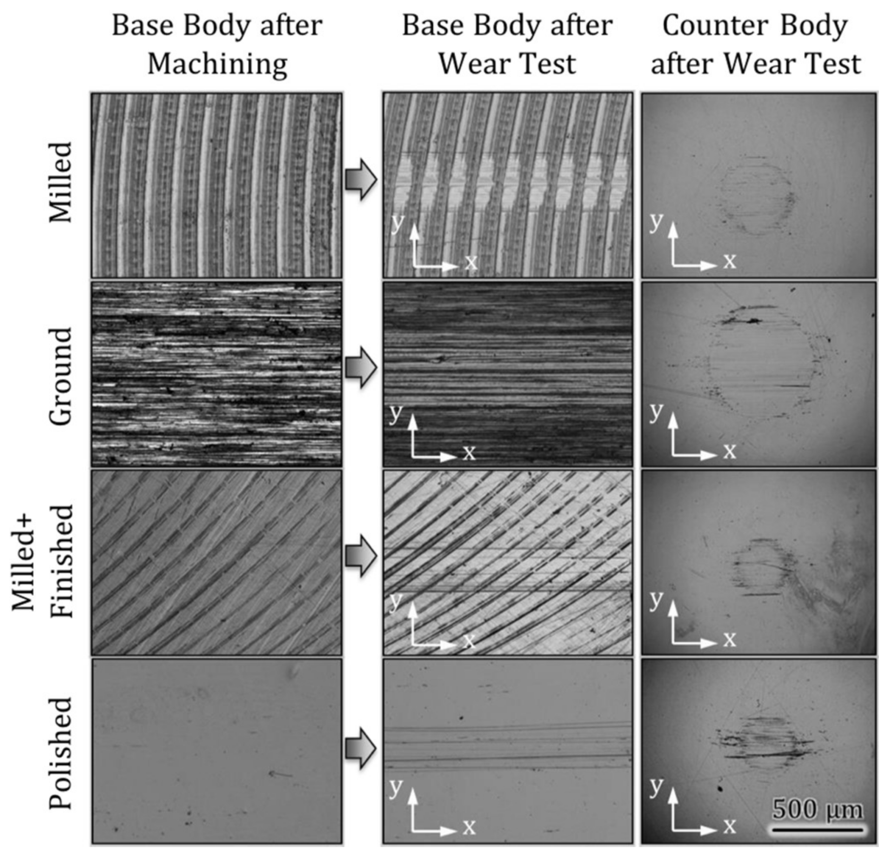
Figure 5.
Surface appearances of milled samples after wear tests. Direction x is parallel to the relative velocity.
Figure 5.
Surface appearances of milled samples after wear tests. Direction x is parallel to the relative velocity.

Figure 6.
Surface appearances of the polished counter bodies after wear tests. (a) tested against the milled base body; (b) tested against the ground base body; (c) tested against the milled + finished base body; (d) tested against the polished base body. Direction x is parallel to the relative velocity.
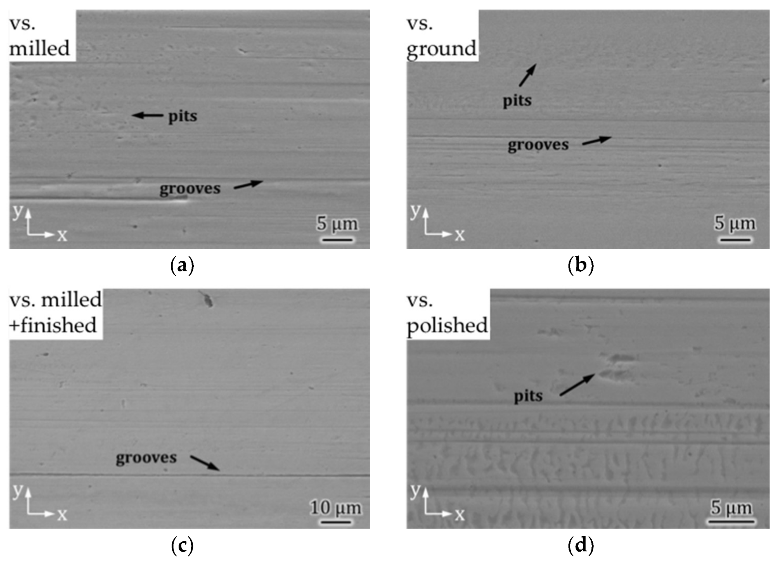
Figure 7.
Surface appearances after the CI/BS wear tests. Direction x is parallel to the relative velocity.
Figure 7.
Surface appearances after the CI/BS wear tests. Direction x is parallel to the relative velocity.
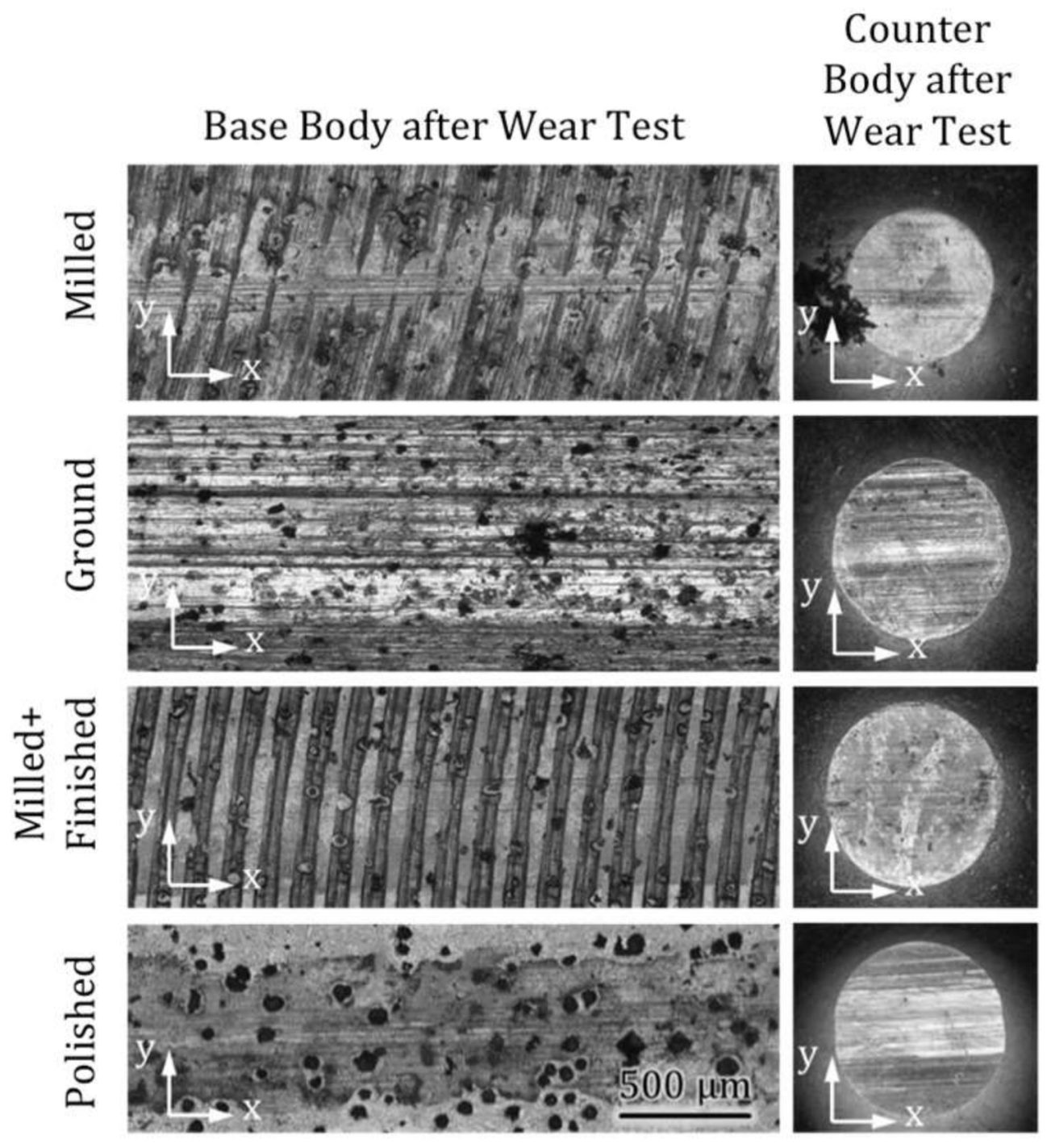
Figure 8.
Surface appearances of the base bodies after CI/BS wear tests. (a) tested against the milled base body; (b) tested against the ground base body; (c) tested against the milled + finished base body; (d) tested against the polished base body. Direction x is parallel to the relative velocity.
Figure 8.
Surface appearances of the base bodies after CI/BS wear tests. (a) tested against the milled base body; (b) tested against the ground base body; (c) tested against the milled + finished base body; (d) tested against the polished base body. Direction x is parallel to the relative velocity.
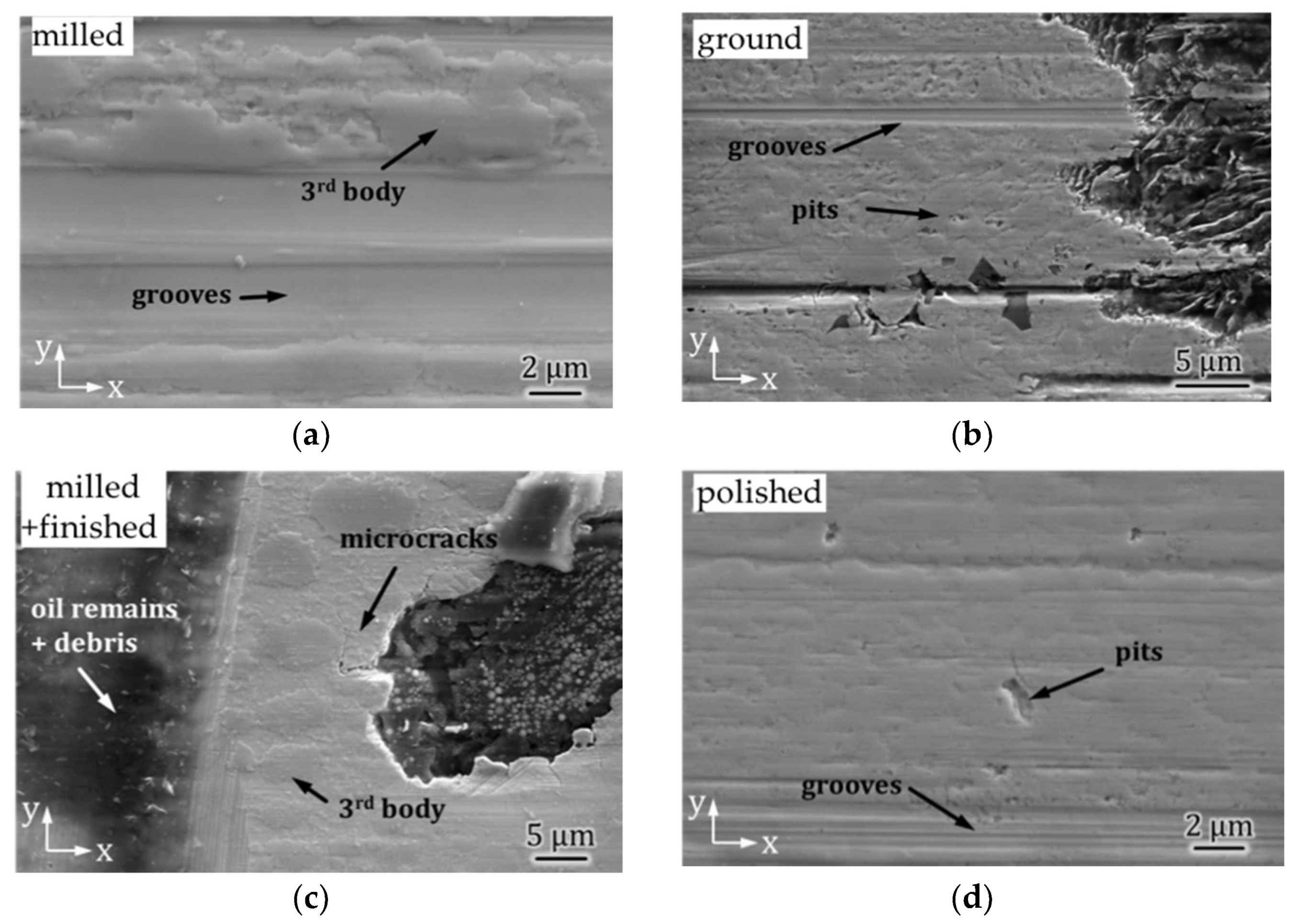
Figure 9.
Metal sheath over a graphite nodule from machining of a milled sample after wear tests. Direction x is parallel to the relative velocity.
Figure 9.
Metal sheath over a graphite nodule from machining of a milled sample after wear tests. Direction x is parallel to the relative velocity.
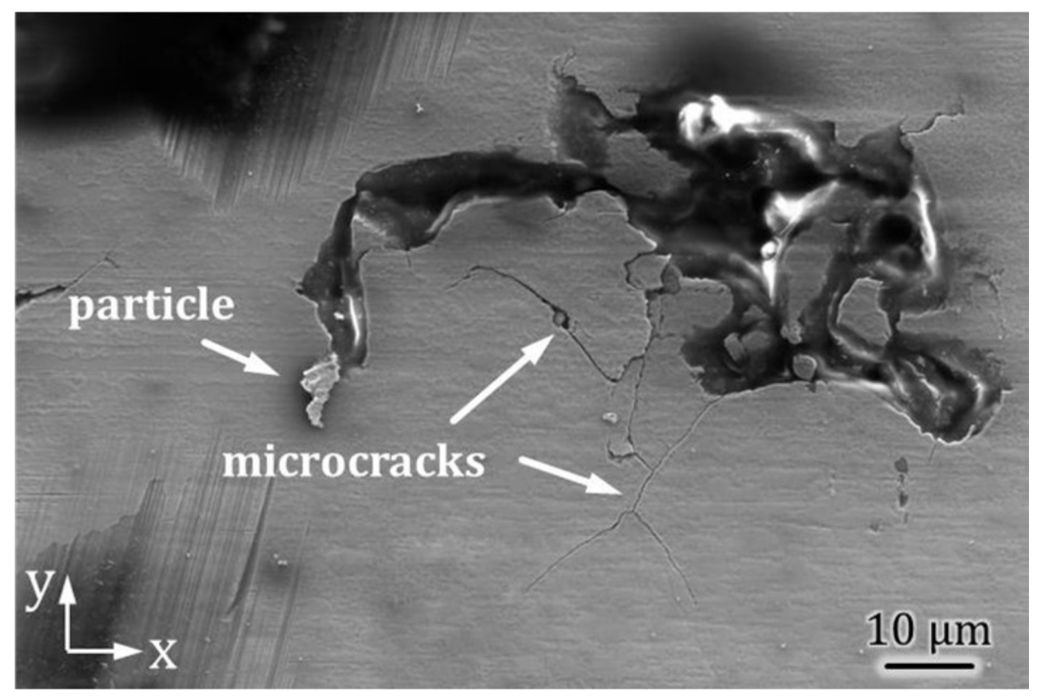
Figure 10.
Surface appearances of the counter bodies after CI/BS wear tests. (a) tested against the milled base body; (b) tested against the ground base body; (c) tested against the milled + finished base body; (d) tested against the polished base body. Direction x is parallel to the relative velocity.
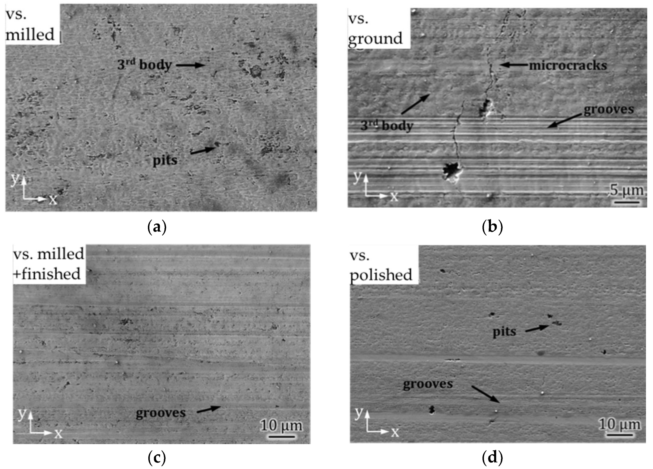
Figure 11.
The main wear mechanisms and known related submechanisms (shaded).
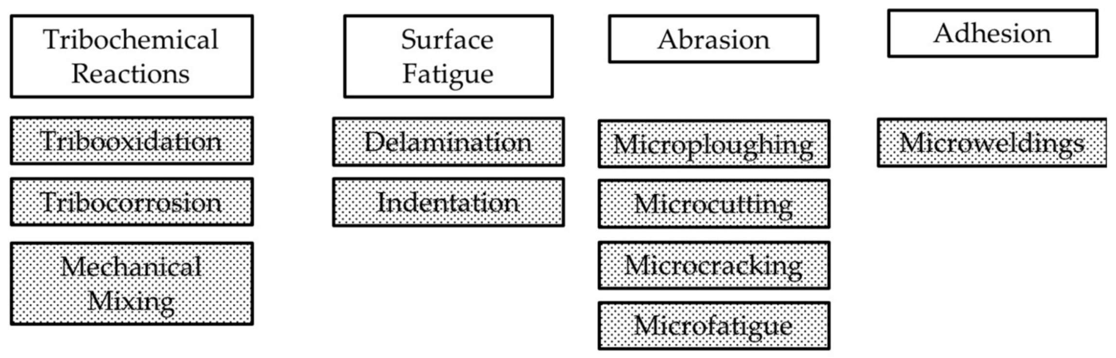
Figure 12.
Scheme of surface and subsurface structures generated under tribological stresses based on [30,34,46].
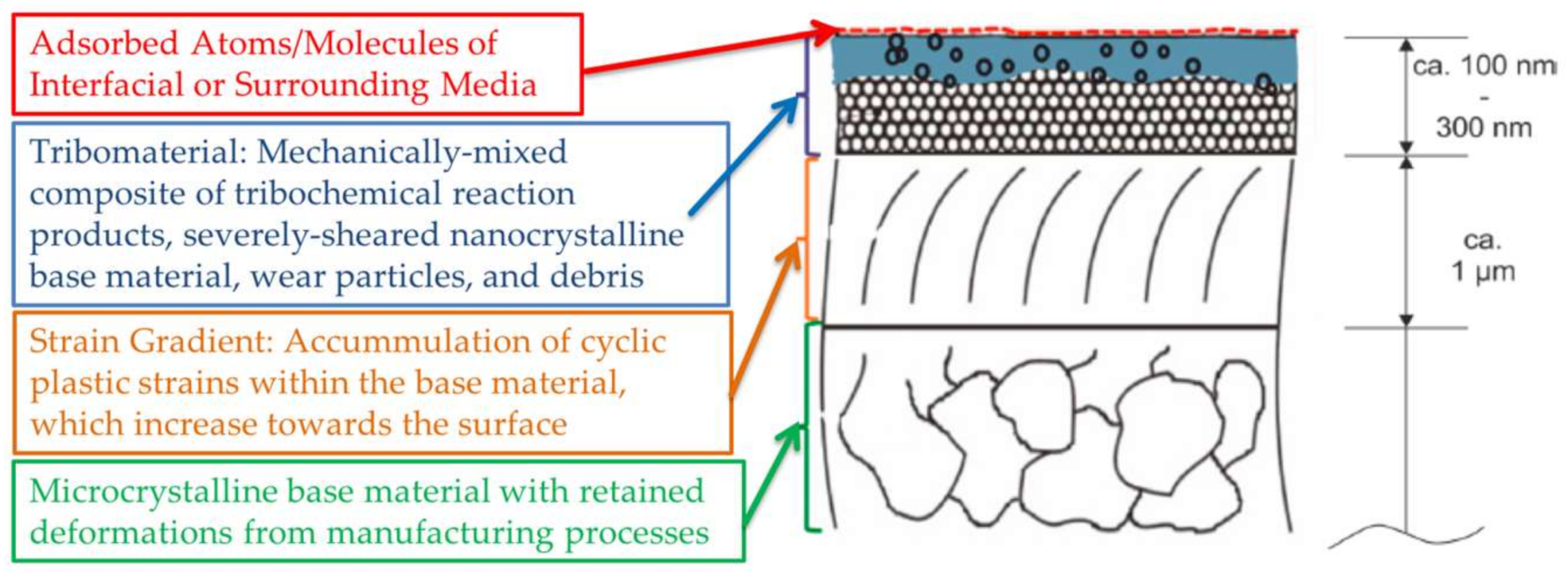
Figure 13.
Taper Sections of the milled base body after the CS/CS wear tests. (a) the microcrystalline martensite of the bulk is covered by a structure-less layer at the surface. The white arrow depicts the interface between the structure-less layer and the bulk (b) The bright field transmission electron microscopy (TEM) micrograph and diffraction pattern reveal a nanocrytsalline martensitic structure with cementite precipitates. The dotted line represents the milled surface.

Figure 14.
KAM results of taper sections of the milled base body; (a) before the wear test; the solid line represents the milled surface; (b) after the wear test; the solid line represents the surface after the wear test. Direction x is parallel to the relative velocity.
Figure 14.
KAM results of taper sections of the milled base body; (a) before the wear test; the solid line represents the milled surface; (b) after the wear test; the solid line represents the surface after the wear test. Direction x is parallel to the relative velocity.

Figure 15.
Bright field TEM micrographs and corresponding diffraction patterns of the subsurface microstructure after the CS/CS wear test; (a) bulk material; (b) strain gradient; (c) tribomaterial.
Figure 15.
Bright field TEM micrographs and corresponding diffraction patterns of the subsurface microstructure after the CS/CS wear test; (a) bulk material; (b) strain gradient; (c) tribomaterial.
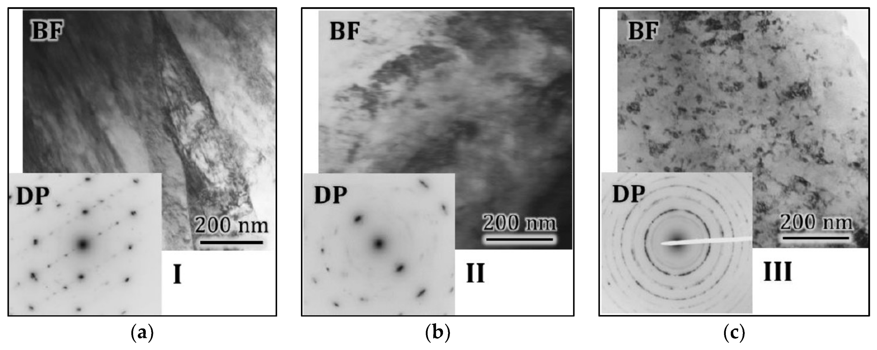
Figure 16.
SEM micrographs of taper sections of the counter body (a) before and (b) after the CS/CS wear test against the milled base body.
Figure 16.
SEM micrographs of taper sections of the counter body (a) before and (b) after the CS/CS wear test against the milled base body.

Figure 17.
Kernel average misorientation (KAM) results of taper sections of the milled + finished base body; (a) before the wear test; (b) after the wear test. The solid line in (a) represents the milled surface; the solid line in (b) the surface after the wear test. Direction x is parallel to the relative velocity.

Figure 18.
Taper sections of the polished counter body after wear test against the milled + finished base body; (a) KAM results; the solid line represents the surface after the wear test (b) TEM bright field micrograph and diffraction pattern of the near-surface zone; Direction x is parallel to the relative velocity.
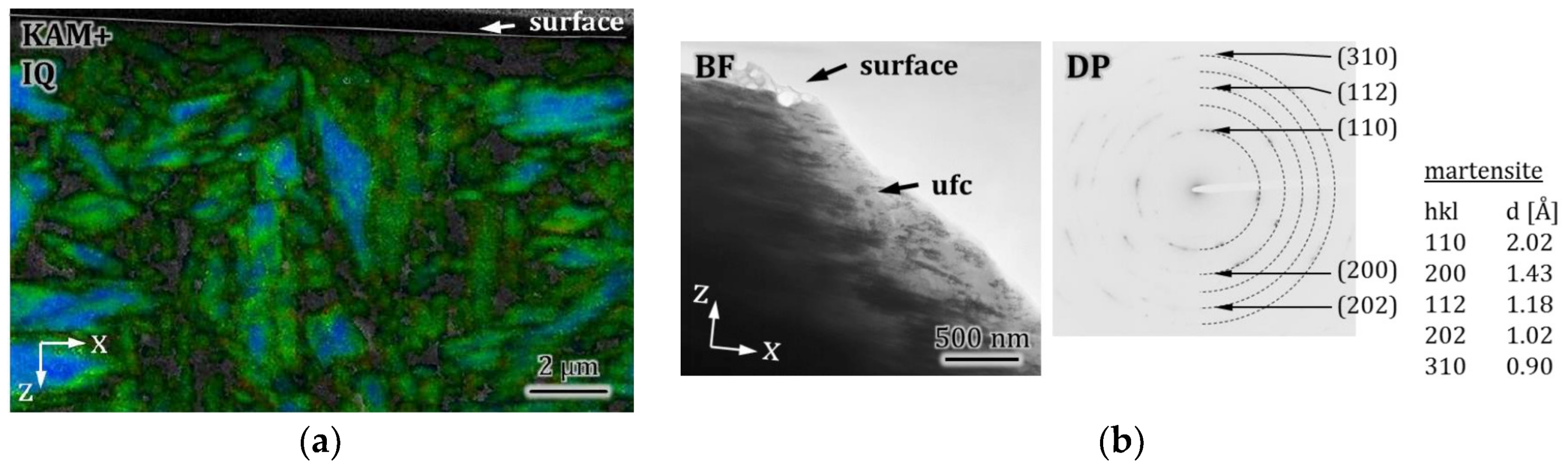
Figure 19.
Depths of wear tracks and thicknesses of strain gradients and tribomaterials of the CS/CS tribocouples after 2 × 10⁶ sliding cycles; (a) counter bodies before wear tests; (b) base bodies before wear tests; (c) counter bodies after wear tests; (d) base bodies after wear tests.
Figure 19.
Depths of wear tracks and thicknesses of strain gradients and tribomaterials of the CS/CS tribocouples after 2 × 10⁶ sliding cycles; (a) counter bodies before wear tests; (b) base bodies before wear tests; (c) counter bodies after wear tests; (d) base bodies after wear tests.

Figure 20.
KAM results of taper sections of the base bodies after the CI/BS wear tests; (a) milled; (b) ground; (c) milled + finished; (d) polished. The solid line represents the surface after the wear test. Direction x is parallel to the relative velocity.
Figure 20.
KAM results of taper sections of the base bodies after the CI/BS wear tests; (a) milled; (b) ground; (c) milled + finished; (d) polished. The solid line represents the surface after the wear test. Direction x is parallel to the relative velocity.

Figure 21.
Depths of wear tracks and thicknesses of strain gradients and tribomaterials of the CI/BS tribocouples after 2 × 10⁶ sliding cycles; (a) counter bodies before wear tests; (b) base bodies before wear tests; (c) counter bodies after wear tests; (d) base bodies after wear tests.
Figure 21.
Depths of wear tracks and thicknesses of strain gradients and tribomaterials of the CI/BS tribocouples after 2 × 10⁶ sliding cycles; (a) counter bodies before wear tests; (b) base bodies before wear tests; (c) counter bodies after wear tests; (d) base bodies after wear tests.

Figure 22.
SEM micrographs of taper sections of the counter bodies after the CI/BS wear test against (a) the milled; (b) the ground; (c) the milled + finished; (d) the polished base bodies. Direction x is parallel to the relative velocity.
Figure 22.
SEM micrographs of taper sections of the counter bodies after the CI/BS wear test against (a) the milled; (b) the ground; (c) the milled + finished; (d) the polished base bodies. Direction x is parallel to the relative velocity.

Table 1.
Parameters of the used laboratory tribosystems.
| Tribocouple | CS/CS | CI/BS | |
|---|---|---|---|
| Base Body | Carburized 17CrNiMo7-6 | Flame-hardened EN GJS265HB | |
| Counter Body | Carburized 17CrNiMo7-6 Pin | 100Cr6 Ball | |
| Tip/Ball Radius | mm | 5 | |
| Stroke | mm | 6 | |
| Normal Force | N | 30 | |
| Test Frequency | Hz | 5 | |
| Lubricant | Mobilgear SHC XMP 320 | Mobile 1™ ESP Formula SW-30 | |
| Viscosity at 40 °C | cSt | 320 | 72.8 |
| Lubricant Temperature | °C | 20 | 80 |
Table 2.
Coefficient of friction (COF) at end of tests, accumulated frictional energy Ed, average volumetric Wv and linear WL wear rates of base bodies (BB) and counter bodies (CB) after 2 × 10⁶ sliding cycles. WL was iterated from the volumetric numbers by simple geometrical assumptions. Zero does not mean that there was no wear at all, but we could not measure it with respect to the resolution of the equipment used. Thus, they must have been much smaller than 1 nm/h.
| Tribocouple | CS/CS | CI/BS | ||||||||
|---|---|---|---|---|---|---|---|---|---|---|
| Machining | Milled | Ground | m + f | Polished | Milled | Ground | m + f | Polished | ||
| COF | - | 0.084 ± 0.003 | 0.108 ± 0.003 | 0.088 ± 0.0005 | 0.093 ± 0.002 | 0.12 ± 0.0025 | 0.074 ± 0.007 | 0.14 ± 0.0012 | 0.073 ± 0.003 | |
| Ed | kJ | 65 | 81 | 62 | 68 | 88 | 50 | 91 | 50 | |
| WV | BB | ×106 in µm3 | 0.33 | 0.15 | 0.00 | 0.00 | 0.80 | 0.22 | 1.30 | 0.45 |
| CB | 0.17 | 0.57 | 0.02 | 0.02 | 0.70 | 1.28 | 1.10 | 1.05 | ||
| WL | BB | nm/h | 2 | 1 | 0 | 0 | 3 | 1 | 5 | 2 |
| CB | 30 | 54 | 10 | 10 | 60 | 81 | 75 | 74 | ||
Table 3.
Main Wear Mechanisms and their Submechanisms.
| Main Wear Mechanisms | Tribochemical Reactions | Surface Fatigue | Abrasion [35] | Adhesion [40] |
|---|---|---|---|---|
| Submechanisms | Tribooxidation [41] | Delamination (by predominantly elastic interaction of solid contacts [42]) | Microploughing | Material Transfer |
| Tribocorrosion [43] | Indentation (by predominantly plastic interaction of solid contacts [37]) | Microcutting | ||
| Mechanical Mixing [44] | Microcracking | |||
| Microfatigue |
© 2018 by the authors. Licensee MDPI, Basel, Switzerland. This article is an open access article distributed under the terms and conditions of the Creative Commons Attribution (CC BY) license (http://creativecommons.org/licenses/by/4.0/).
Share and Cite
MDPI and ACS Style
Stemmer, P.; Fischer, A. Pathways of Dissipation of Frictional Energy under Boundary Lubricated Sliding Wear of Martensitic Materials. Lubricants 2018, 6, 34. https://doi.org/10.3390/lubricants6020034
AMA Style
Stemmer P, Fischer A. Pathways of Dissipation of Frictional Energy under Boundary Lubricated Sliding Wear of Martensitic Materials. Lubricants. 2018; 6(2):34. https://doi.org/10.3390/lubricants6020034
Chicago/Turabian StyleStemmer, Priska, and Alfons Fischer. 2018. "Pathways of Dissipation of Frictional Energy under Boundary Lubricated Sliding Wear of Martensitic Materials" Lubricants 6, no. 2: 34. https://doi.org/10.3390/lubricants6020034
Note that from the first issue of 2016, this journal uses article numbers instead of page numbers. See further details here.