Modeling the Friction Boundary Layer of an Entire Brake Pad with an Abstract Cellular Automaton

TU Braunschweig–Institute of Dynamics and Vibrations, Schleinitzstraße 20, Braunschweig 38106, Germany
*
Author to whom correspondence should be addressed.
Lubricants 2018, 6(2), 44; https://doi.org/10.3390/lubricants6020044
Submission received: 13 April 2018
/
Revised: 26 April 2018
/
Accepted: 2 May 2018
/
Published: 4 May 2018
(This article belongs to the Special Issue Computer Simulation in Tribology and Friction)
Abstract
:The principle energy exchange of a brake system occurs in the tribological boundary layer between the pad and the disc. The associated phenomena are primarily responsible for the dynamics of brake systems. The wear debris forms flat contact structures, or “patches,” which carry the majority of the normal load in the system and are highly influential on the friction behavior of the system. A new simulation tool is presented, which is capable of rapidly performing simulations of the contact between an entire brake pad and disc. The “Abstract Cellular Automaton” simulations accurately model the patch coverage state of a brake pad surface based on the system’s load history. This can be used to simulate the complex dissipation phenomena within the tribological contact of the entire pad, including time-dependent local friction coefficients, wear and wear debris transport, and vibrational effects on highly differing scales.
1. Introduction
1.1. Background
The dynamics of automotive brakes have come into the focus of research and development in recent decades. The goals of these investigations include achieving an adjustable coefficient of friction, optimizing NVH behavior, and minimizing particle emissions.
1.2. Formulation of the Problem
The study of the dynamic friction behavior of automotive braking systems is a multifaceted, interdisciplinary pursuit. It presents numerous challenges to academic researchers and great efforts and resources have been devoted to achieving a better understanding of this behavior in the automotive industry. In order to understand the friction behavior of brake systems, wide ranges of tests are carried out on a daily basis, over a broad scope of standards and specializations of interest. Such measurements generally require high-power, precise measurement equipment, and introduce many costs to the research organization. While some general tendencies have been observed, measurements usually do not offer detailed insight into the fundamental processes that occur at the contact interface between a brake pad and disc. Typically, the friction interface cannot be observed during measurement, and the relevant tribological forces are typically measured indirectly through the resulting friction torque in the system, with many system components separating the sensors from the friction interface.
It is therefore very difficult to develop and test a comprehensive theory of the fundamental boundary layer phenomena in tribological contacts. This presents a major obstacle to achieving the greater goal of establishing a robust means of predicting, and ultimately designing, the behavior of a friction pair.
1.3. Literature Survey
In recent years, the aforementioned limits of standard brake measurements have been pushed. For example, Gramstat et al. [1] made use of a transparent disc material in order to directly observe the formation of contact structures in the friction interface. Furthermore, reduced-scale tribometers have been developed, which enable highly accurate measurements of the relevant forces very close to the friction interface [2,3,4]. Nevertheless, the limitations and costs of measurements introduce the need for additional alternatives.
Computer-aided engineering tools can be used to investigate the fundamental phenomenological processes that occur in real-life braking scenarios. Simulations based on finite element methods (FEM) can be quite accurate, but tend to be computationally demanding and are therefore generally constrained to small studies. Another difficulty is the description of wear processes within these tools. In the interest of performing more efficient studies, alternative simulation tools have been developed. Such alternatives may focus on the phenomena that have the most profound influence on the friction behavior, while improving performance through (for example) simplified consideration of other aspects and/or scaling down the simulation domain.
One solution is to focus the simulation on the tribological boundary layer of the system, which is primarily responsible for the friction dynamics of the brake system. This boundary layer is characterized through a highly complex dynamic coupling of topography, friction, and wear, which are substantially influenced by the materials of the friction partners and braking conditions.
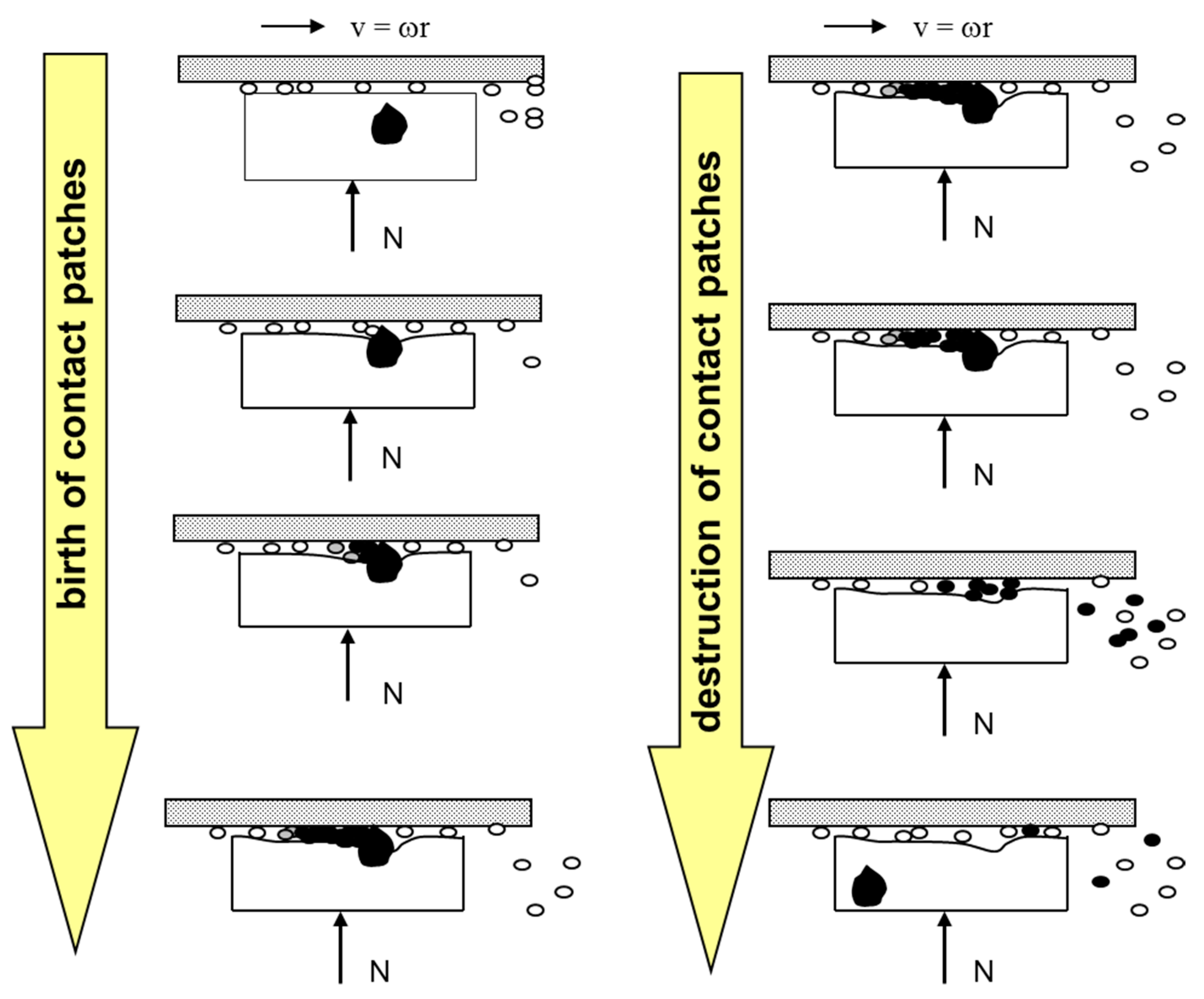
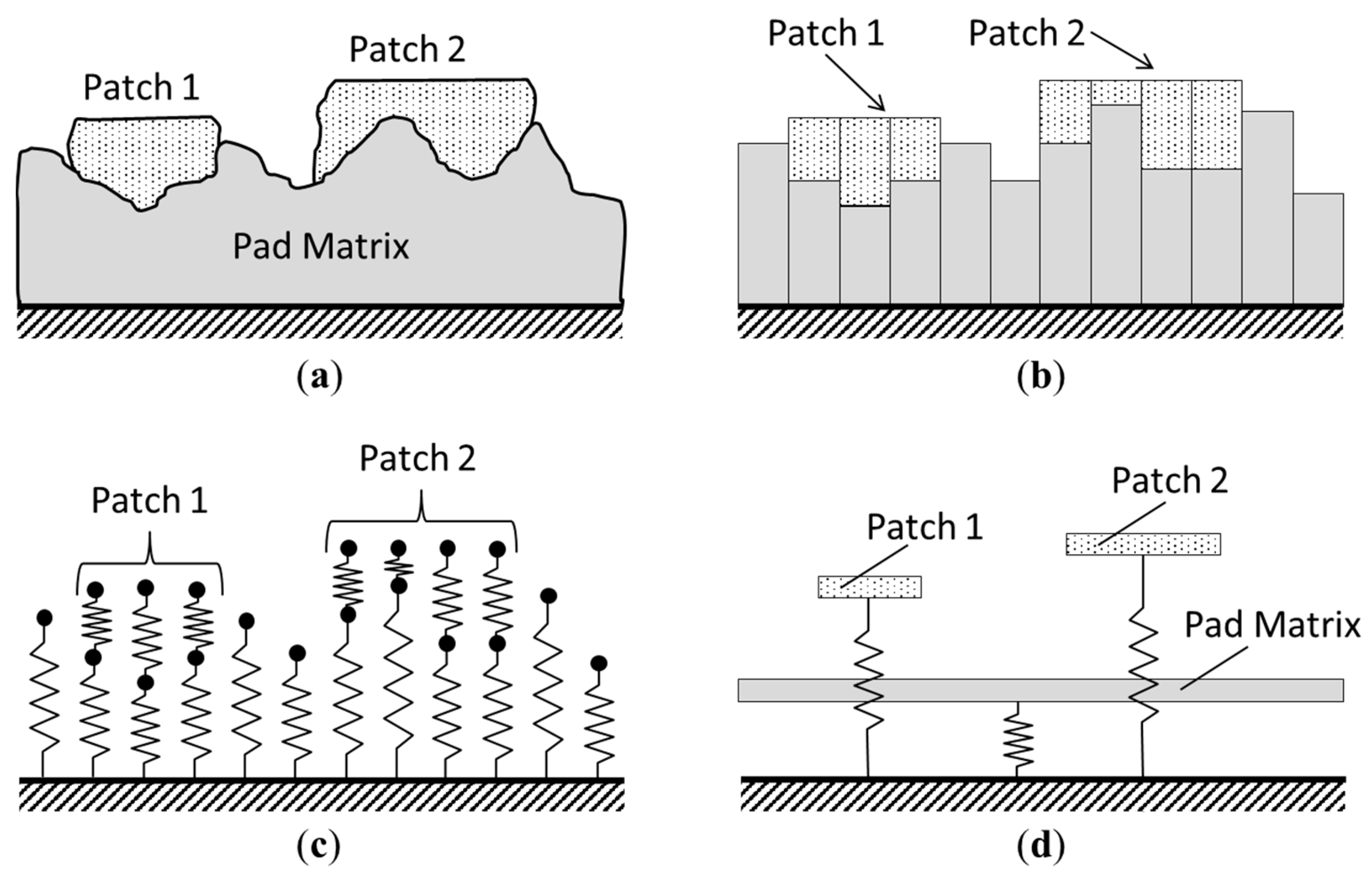
Simulation tools have been developed, for example, based on the key assumption that the combined dynamics of contact plateaus, or “patches”, in the tribological interface have a dominant influence on the global friction signature of the brake system. The dynamics of how these patches come into existence, grow, and collapse are illustrated in Figure 1. As seen in this figure, wear particles flow between the brake disc and the inhomogeneous brake pad. The brake pad is gradually worn down, and a hard particle within the pad comes to the surface. At the location of contact between this hard particle and the disc, wear dust is unable to flow, and therefore accumulates. If this hard particle is much more wear-resistant than the surrounding polymer matrix, the hard particle is pressed more and more into the matrix, concentrating the normal load in this local surface. Through this process, the agglomeration of wear dust encounters high pressures and temperatures, and can undergo physical and chemical changes, often becoming coated with a protective metal oxide layer. The result is a hard and flat structure that is raised above the average surface height of the brake pad. These patches are understood to carry the majority of the normal load on the brake pad and are therefore highly influential with respect to the friction behavior of the brake system. These brittle structures continue to undergo severe loading conditions and can eventually become damaged, at which point they are believed to nearly instantaneously return into the flow of wear dust. These processes may occur simultaneously at thousands of locations within the friction contact between a brake pad and disc. These contact plateaus were first described in Ref. [5], and their implication on the friction dynamics of brake systems was postulated in Ref. [6].
Figure 2a shows a photograph of a brake pad with visible patches on it (black regions).
The patches visible in Figure 2a are much larger than average. Theoretically, there are also many hundreds or thousands of smaller patches within the tribological boundary layer, which are observable only upon further magnification, as shown in Figure 2b.
As the dynamics of the patches in the friction interface are understood to be a crucial source of the dynamic signature of the coefficient of friction of brake systems [6,8], several simulation tools have been developed based on patch theory. Some of these have employed a classical, grid-based cellular automaton approach [9]. The grid-based cellular automata are based on a fine discretization of an area of interest. Each cell within this discretized grid is analyzed based on the current states of itself and its neighboring cells. A finite set of rules are used to compute, for example, the physical and chemical interactions of the individual cells. These simulation tools have aided in furthering the understanding of how patch dynamics influence the friction behavior of brake systems, based on a scaled-down brake pad sample (about 0.1%–1% of a total brake pad) encompassing a representative material mixture. For example, one such cellular automaton was comprised of a 150 × 150 cell grid, with each cell being 50 × 50 µm2 in area. These simulations focused on detailed analyses of local effects on a mesoscopic level [7,10].
These tools are capable of performing detailed simulations of complex material mixtures and have been validated through a series of specialized measurements. They have aided in gaining insights into the dependencies of the patches’ dynamics, particularly with regard to surface pressure, sliding speed, and temperature. The grid-based cellular automaton introduced a wear particle density flow, modeled using the local contact scenario for generating patch growth. The patch growth process was formulated based on the dynamics of macroscopic bulk goods. While information from this automaton corresponds very well with the local friction behavior, the local heat generation, the local wear behavior, and the distribution of patch areas, the individual patch size was only correct in a statistical sense. In addition, global effects on the brake pad, such as those related to thermoelastic instabilities [11], could not be represented with these tools. Due to the numerical complexity, the grid-based automaton cannot currently be extended to simulate the entire contact area between a brake pad and disc.
1.4. Contribution of This Study
A new method has been developed towards simulating the tribological phenomena associated with automotive braking. The Abstract Cellular Automaton combines the techniques of classical, grid-based automata with those of N-body simulations. Unlike previous simulation techniques, the computational resources are focused on the detailed analysis of the contact plateaus (patches), which are primarily responsible for the characteristic behavior of high-load contacts. Through detailed investigations of these mesoscopic, local structures and coarsely discretized bulk elements, efficient computations of the tribological boundary layer are enabled. The computational resources allocated to a given location in the contact are commensurate with the influence of the corresponding local tribological phenomena on the global system behavior. This is made possible through a priori knowledge of the role of patch dynamics in high-load contacts. Thus, the boundary layer between an entire brake pad and disc can be simulated relatively quickly using a standard computer. These simulations enable investigations into the interactions between highly detailed, local phenomena and global, macroscopic behaviors. This can contribute to an improved understanding the fundamental tribological mechanisms associated with observable system behaviors.
1.5. Organization of This Paper
This paper sets out to introduce this new simulation tool. In Section 2, its fundamental principles are explained, including detailed descriptions of some crucial program functions and a summary of the relevant operating parameters. In Section 3, example studies and results are presented, offering an overview of some of the Abstract Cellular Automaton’s capabilities and potential. These results are further contextualized through the discussion in Section 4. Finally, the work presented in this paper is summarized and future studies are outlined.
2. Materials and Methods
Recently, a new computational tool has been developed for simulating of the tribological interface between a brake pad and disc. The Abstract Cellular Automaton is based upon the same physical principles as the aforementioned cellular automata, but models the patches in a new way, and is structured differently from a programming perspective. This development was motivated by the facts that the individual tangential motion of patches can be essential to the NVH behavior of the entire pad [12], and that the contour of the patches was not essential at any stage in the realization of the grid-based automaton. It follows that each patch can be modeled for simplicity as a rigid disc of constant thickness on an elastic matrix. The size dynamics of the patches require a locally-resolved wear particle flow, which is realized in the grid-based automata by local balance equations taking into account the friction properties and the patch coverage state of the brake pad. To integrate the principles of N-body simulations and classic grid-based cellular automata, we introduce an automaton with generalized neighborhood properties, where each patch is one cell. The result is a simulation software that produces global results comparable to those attained using the classic grid-based cellular automata simulations [13]. Through its innovative structure and use of simplified algorithms, the Abstract Cellular Automaton implements the insights gained through the development and use of the classical grid-based cellular automata, while offering significant computational advantages compared to these predecessors and computing solutions of the entire pad-disc contact under realistic normal load distributions.
This work presents several functions and algorithms implemented in the Abstract Cellular Automaton. Many setting parameters are introduced, whose values are selected based on the results of complex validation simulations carried out on the Abstract Cellular Automaton as well as on classic grid-based automata, not all of which are shown in this work. These parameters () are defined and described within the body of this work and in the list of nomenclature. As the structures of the friction boundary layer (i.e., patch dynamics) in high-load contacts such as automotive brakes are a stable tribological effect, these parameters can be adjusted without significantly influencing the simulated phenomena. The used values aid in the fine-tuning of the simulation program to improve the performance for simulating semi-met brake pads. Another set of values would be implemented to simulate NAO brake pads, which differ from semi-met pads based on differing statistical parameters, not due to differing tribological mechanisms.
The Abstract Cellular Automaton was first documented in Ref. [13], where its functionality was validated based on comparison studies with the grid-based cellular automata. It is a simulation tool developed with the intention of modeling the dynamic signature of the coefficient of friction at the tribological interface of an automotive braking system based on the theories of patch dynamics. The emergent simulated friction characteristics that come about through considerations of the patch dynamics can offer insights into true physical systems. In comparison to its predecessors (described above), the Abstract Cellular Automaton employs a reduction of fundamental physical parameters in the model. It strives to aid in the understanding of the dynamic processes relating to patch growth, birth, and collapse, as they interact with the fundamental tribological phenomena of the system. As the Abstract Cellular Automaton is capable of rapidly simulating the tribological interface between an entire brake pad and disc, up to 100,000 patches can be simulated simultaneously. Knowledge and insights gained through the development and implementation of the classic grid-based cellular automata were used towards the development of the Abstract Cellular Automaton. For example, the highly-detailed patch shape and location information attained using the grid-based cellular automata does not have a significant influence on the global macroscopic results. The Abstract Cellular Automaton therefore generalizes this type of information, simplifying computations without significant trade-offs in accuracy within its scope. The highly detailed, explicit simulations of the grid-based cellular automata are used towards the validation of the elementary processes of the Abstract Cellular Automaton.
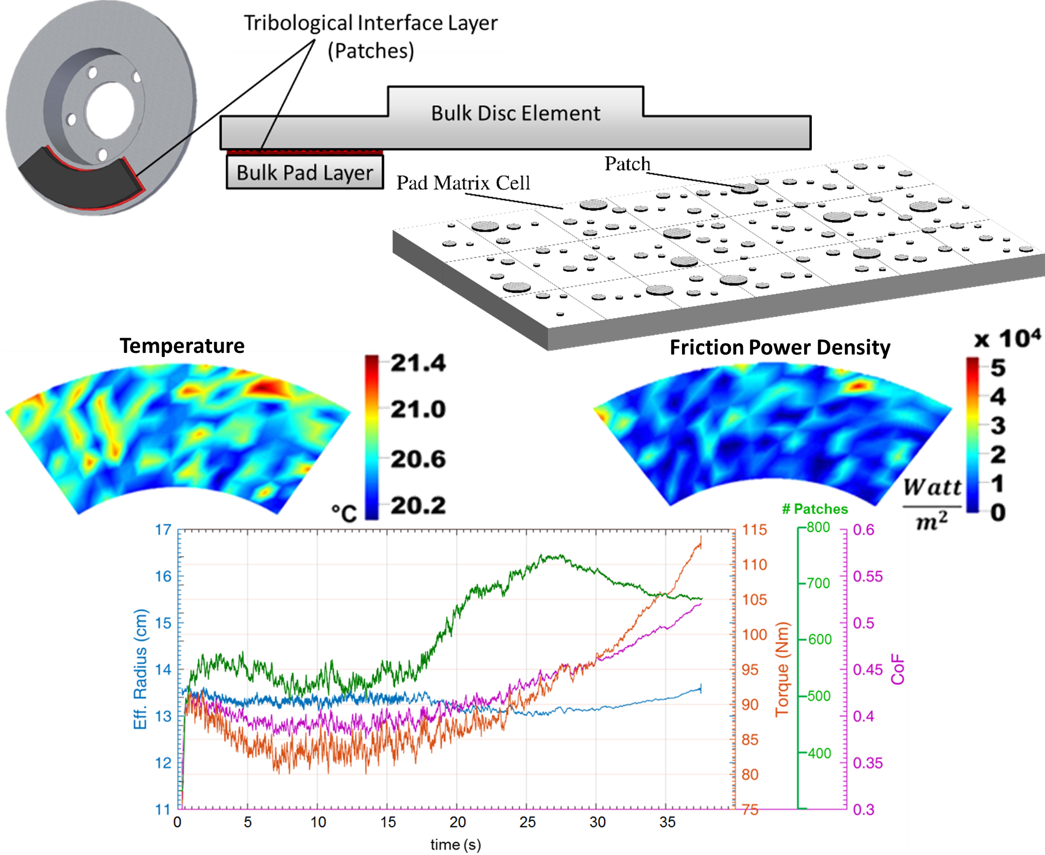
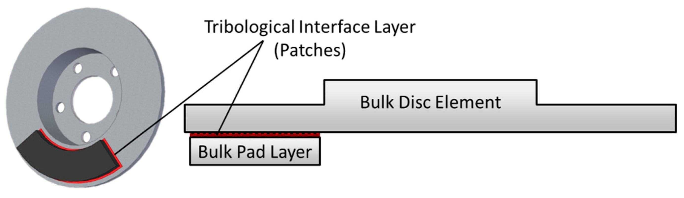
The benefits introduced by the Abstract Cellular Automaton come from its underlying structure. The task of analyzing the entire brake pad is carried out in two separate layers, as outlined Figure 3.
As the tribological interface between the pad and the disc has the most substantial influence on the friction behavior of the system, the computational effort is focused on this layer, which is modeled through an analysis of the contact patches in the interface. These computations are carried out using an approach similar to that of N-body simulations. A linked list containing pointers to all of the patches is implemented. At each time step, a series of functions are carried out at each individual patch. Here, the physics within the individual patches are computed, along with the following interactions: patch-pad (interaction between patches and the bulk matrix material of the brake pad; for example, thermal conduction), patch-disc (for example, friction), and patch-patch (interactions between neighboring patches). An example of a patch-patch interaction is the tangential elastic coupling between patches, which will be discussed below.
The bulk matrix material of the brake pad (pad matrix) is also considered in the analysis, albeit in a less detailed manner than the individual patches. For this portion of the simulation, it is assumed to be sufficient to consider the pad matrix in the form of a coarsely discretized grid. This is implemented using a classical grid-based cellular automaton approach, negligibly increasing the computational effort due to the relatively low number of pad matrix cells compared to the number of patch cells. The discretization size is chosen such that all relevant computations are numerically stable, and may be adjusted if higher resolution results are needed. Such adjustments do not affect the simulated tribological dynamics or mechanisms, although small numerical influences follow. Figure 4 provides a general impression of how the linked list of patches is superimposed on the pad matrix.
In the pad matrix layer, the physics within each cell are computed, along with the following interactions: cell–disc (for example, friction between the pad matrix and the disc), cell-environment, and cell–cell (interactions between neighboring cells of the pad matrix). These interactions primarily concern heat transfer phenomena. The brake disc is currently modeled as a single, homogeneous element. The various interactions between the main simulation components are summarized in Figure 5.
The prioritization of computational effort into the tribological interface, combined with the modeling techniques implemented, enable simulations to be run much faster than both common FEM studies and simulations from the classical cellular automaton programs.
Towards simulating friction in the tribological interface, the Abstract Cellular Automaton is capable of flexible implementation of various types of friction rules. For simple investigations, the assumption of constant Coulomb friction is a reasonable approximation. Here, a constant coefficient of friction is assigned to the contact between each patch and the disc. The contact between the pad matrix and the disc is generally assigned a lower friction value.
For more in-depth investigations, in which, for example, the patches are modeled as individual self-excited oscillators, it is reasonable to approximate friction as a function with a negative gradient with respect to the sliding speed. Further investigations require, for example, temperature-dependent friction states [14].
The local friction coefficient can also be iteratively improved through the evaluation of the global coefficient of friction, by implementing the global result from one iteration as the local coefficient of friction in the following iteration, and so on. This will be presented in a future work. The use of the dynamic friction rules from Ref. [8] is quite similar to such an optimization of the local friction formulation. Furthermore, different types of patches can be assigned different friction behavior characteristics based on, for example, the conditions under which the patches were formed. Between braking applications, the surfaces of the pad and disc can undergo oxidation effects. The influence of this on the friction behavior of the system is also implemented in the Abstract Cellular Automaton. Here, the difference between coated and non-coated patches is considered. The non-coated patches possess temporary friction characteristics, which can be modeled as the effects of self-locking of the wear particles.
The initial studies and tests performed using the Abstract Cellular Automaton, however, seek to implement relatively simple friction rules. As hundreds or thousands of patches (each exhibiting a simple friction behavior) undergo birth, growth, and collapse processes, interacting with one another and their surroundings, a global friction behavior of the system emerges that can be much more complex than the friction rules themselves.
The global coefficient of friction of the system is calculated as shown in Equation (1):
where is the total number of patches in the system, is the number of pad matrix cells, is the friction force, is the normal force, is the coefficient of friction, and and are placeholders for iterating over the patches and matrix cells, respectively. Each of the individual friction forces are determined based on the individual normal force and friction rule on the given element.
The kinetic energy dissipated through friction and the associated friction power is primarily converted into heat. The resulting increase in temperature and further thermal effects are computed based on the methods described in Ref. [14]. For further information on this, see the literature cited there. In this abstract automaton, the following effects are considered: heat generation due to friction, conduction between patches and their foundation pad cells, conduction between patches and the disc, conduction between the pad and the disc, conduction within the brake pad (between pad cells), and cooling from the environment through convection and radiation.
As a simple friction law is often chosen, the global dynamics of the coefficient of friction largely result from the patch dynamics, or the cumulative effects of the simultaneous creation, growth, and collapse of hundreds or thousands of patches in the tribological interface. When constant friction coefficients are assumed for the patches and for the pad matrix, the global coefficient of friction is primarily influenced by the ratio of total patch surface area to the total pad area in the system. This can be expressed as shown in Equation (2).
where an increase in the total patch surface area is associated with a positive time derivative of the coefficient of friction [8]. This coincides with the assumption that the coefficient of friction between the patches and the disc is greater than the friction coefficient between the pad matrix and the disc.
Figure 6, Figure 7 and Figure 8 show precisely how these dependencies affect the creation, growth, and destruction of patches, respectively. The patch birth algorithm is carried out once per simulation time step. The patch growth and collapse algorithms are each carried out once per patch per time step.
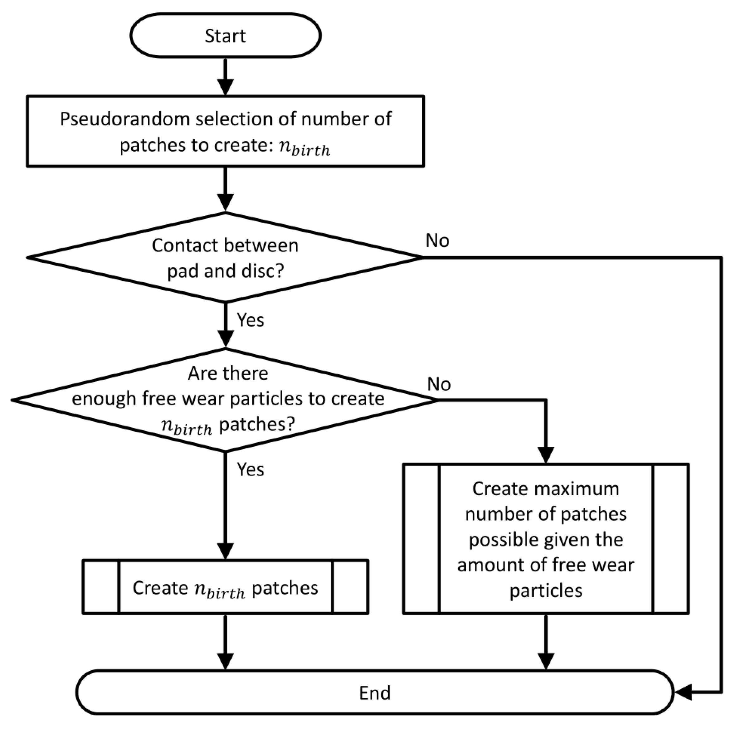
As shown in Figure 6, the only conditions required for patch birth to take place are that the disc and pad need to be in contact, and that a sufficient volume of wear particles is present in the tribological interface to create the respective patches. For simplicity, a single representative patch volume is considered toward determining if the latter condition is satisfied. It is taken into account that the patch density is greater than that of the pad material density (and likewise that of the wear particles). The parameter is comprised of a pseudorandom component with a uniform distribution and deterministic components based on the brake pad material (NAO, low-met) and the simulation time step. For , it can range between 0 and 84. The symbol represents the function floor (x), which returns the greatest integer less than or equal to .
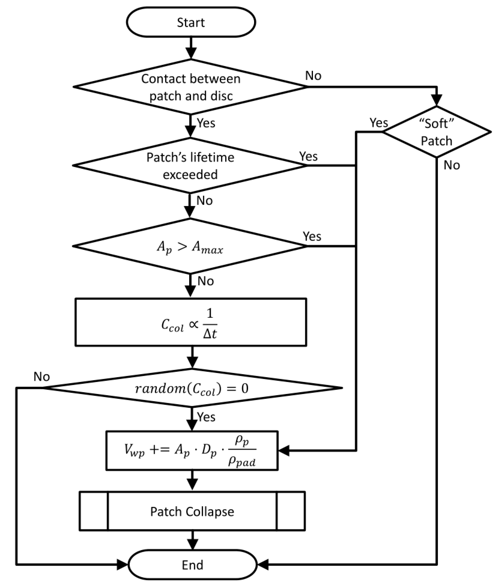
Once a patch already exists in the Abstract Cellular Automaton, it has the potential to increase in surface (and thereby contact) area. The algorithm employed is made explicit in Figure 7. First, the magnitude of the increase in patch area is determined. The square root of the current patch area is used as a factor in this step because new wear particles collect along the perimeter of the patch. The magnitude of patch growth is therefore directly proportional to the size of this perimeter. This value is then scaled according to reference values for the normal force and pad area. If the resulting value is nonzero, the patch is in contact with the disc, and sufficient wear particles are present to form the extra patch mass, growth can theoretically occur. If the patch is a “soft” or “white” patch, meaning that it consists of self-locked wear particles that have undergone no chemical change [15], the conditions for patch growth are already fulfilled and growth occurs. If it is a “hard” or “black” patch, meaning it is coated with an oxide layer, an additional minimum temperature condition must also be fulfilled for growth to occur. When a patch grows, the amount of wear particles needed to create the additional patch mass are removed from the tribological boundary layer.
As seen in Figure 7, the amount of area added on to a patch during growth is proportional to the average relative velocity between the patch and the disc, the time step, the square root of the patch’s surface area, and the normal force. This quantity is weighted with a constant factor to guarantee a realistic order of magnitude. The expression represents updating the variable through compound assignment as follows: . An analogous compound assignment operation for addition () is referred to below.
By definition, “soft” patches are destroyed as soon as they are released from the brake disc and the self-locking mechanism is thus no longer in place. Regardless of patch type, other collapse mechanisms may occur. A patch collapses, for example, if its age exceeds its individual, non-constant lifetime factor (dependent on its load history), or if its size exceeds a fixed, global size limit (). Otherwise, a patch can also collapse as a result of various other effects, which in the Abstract Cellular Automaton are summarized in the form of a random variable . This value is scaled to the simulation time step, aiding the robustness of these simulations to the adjustment of . The term refers to a command that returns a pseudorandom integer within . When a patch collapses, it returns to the friction boundary layer in the form of free wear particles.
As seen in Figure 6 and Figure 7, the creation and growth of patches depend on the amount of wear particles present in the tribological interface. The wear of the brake pad is computed based on the Archard wear equation. The loss of wear particles to the environment is assumed to occur at the rate defined in Equation (3):
where is the total volume of wear particles in the tribological interface, is the simulation time step, is the average sliding speed between the pad and the disc, is the average width of the brake pad, and is a constant model parameter. Based on the authors’ experience, is assumed; the motion of the disc along the full width of the brake pad therefore results in a 25% loss of wear particles to the environment.
“In-stop” braking procedures can also be simulated using the Abstract Cellular Automaton. Early simulations implement this under the assumption that all eight pad-disc interfaces of the automobile undergo identical conditions and exhibit identical responses [16].
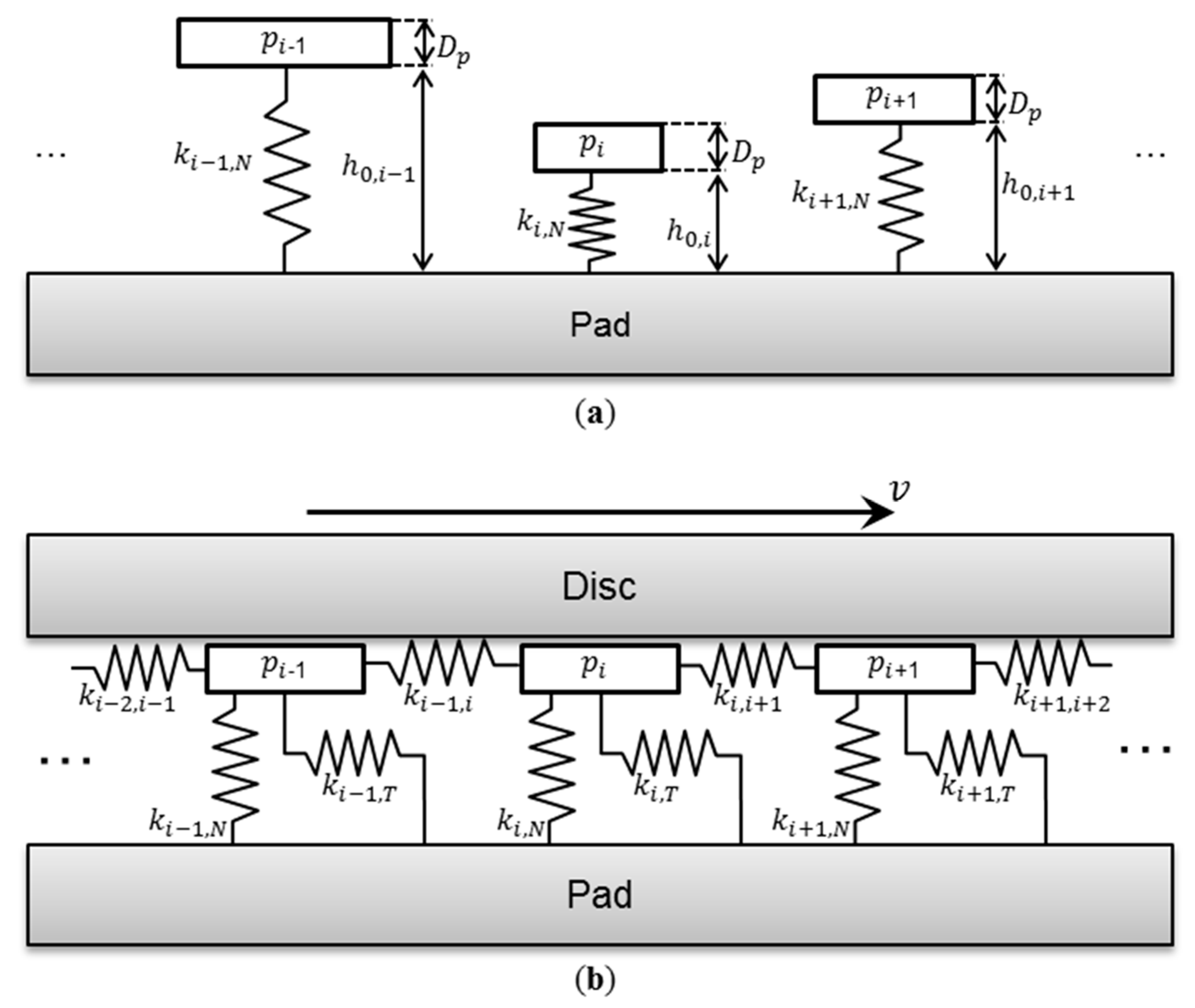
A fundamental aspect of the Abstract Cellular Automaton’s functionality is the calculation of the normal force distribution on the patches and pad matrix. This problem is coupled with the computation of the deformation of the patches and bulk pad material. To attain this information, various potential system models can be implemented.
In early versions of the classical grid-based cellular automata, broad approximations were used to calculate the normal force on the patches and pad matrix cells focused on developing models based on the local discretization of a continuous half-space [7]. This resulted in rather precise results for the normal force and deformations of all cells in the cellular automata, but was associated with significant computational costs. Therefore, instead of a half-space, a Winkler dynamic bedding modulus is assumed, which is achieved without unacceptable accuracy losses. This model is illustrated in Figure 9. For the computation of the normal force distribution, the materials of the patches and pad matrix are considered separately. Here, each matrix cell is represented by an individual spring, and each patch cell is modeled as a second spring, serially connected to the corresponding matrix cell. Known material parameters are implemented for modeling the spring stiffnesses of the pad matrix. The patches are generally considered to be significantly denser and harder than the pad matrix, and are therefore modeled with comparably high spring stiffnesses. Such a model allows for the simple implementation of patches of varying height.
In the Abstract Cellular Automaton, each patch is represented by a single spring, so it necessarily experiences a uniform normal force distribution and deformation. This is a closer representation of the notion that a patch is a hard, flat, surface structure. The implementation of this model is schematically represented Figure 9d.
It is evident in this figure that the Abstract Cellular Automaton offers an advanced class of simplicity, improving performance without sacrificing informational value. Here, it is important to note that the pad matrix element is not directly coupled to the springs of the patches. The pad matrix spring element is first engaged when the deformation of the patches is sufficient for the disc to contact the pad matrix.
While all patches are modeled in the Abstract Cellular Automaton as having the same thickness, or depth , contributing to their volume and lumped mass, they have varying unloaded spring lengths, or heights , as seen in Figure 10a. Thus, the surface roughness of the brake pad material is accounted for.
On a real brake pad, the tangential motion of one patch (along the direction of the disc’s motion) is related to the deformation of the pad material near that patch. The motion of a neighboring patch is coupled to the motion of through this deformation. In the Abstract Cellular Automaton, this coupling is accounted for using a lumped element model based on Ref. [12], as shown in Figure 10b. Here, the coupled vibrations of patches in the friction boundary layer are simulated under the assumption that the patches act as coupled stick–slip oscillators. The tangential coupling of an individual patch to the matrix of the brake pad is simplified through a single, linear spring.
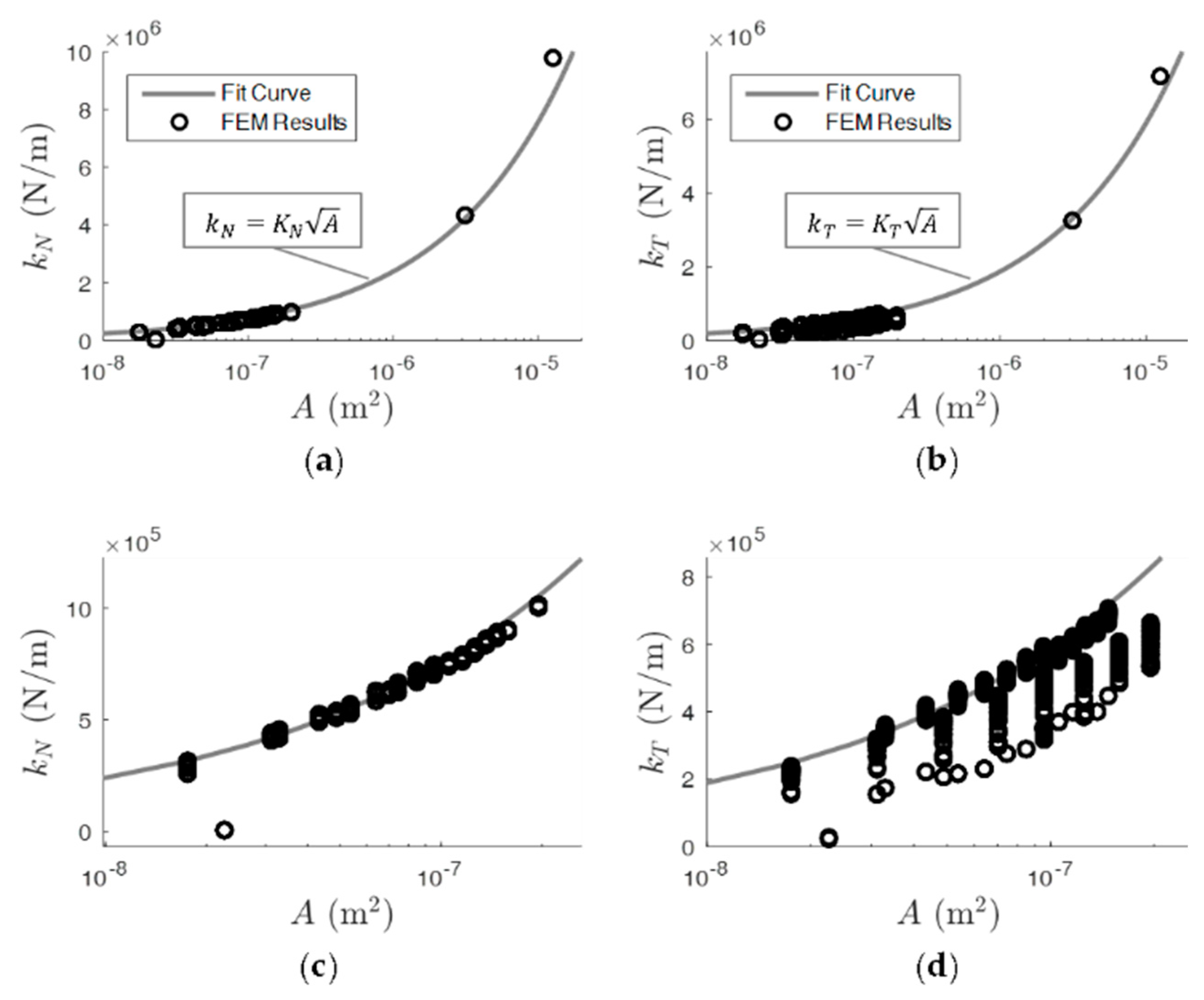
The spring stiffnesses, represented by , are chosen for simplicity based on results from an FEM study on deformations of flat cylindrical structures on the face of a quasi-half-space, as shown in Figure 11.
Here, the spring stiffnesses of an individual patch, , in the normal (, into the pad material) and tangential (, the sliding direction of the disc) directions are shown as functions of the patch’s surface area, .
Figure 11 shows that the stiffnesses of the patches in both the normal and tangential directions can be closely approximated as proportional to the square root of the patch’s area. The resulting functions used are given in Equations (4) and (5):
with the constants and . The tangential stiffness coupling two neighboring patches and is assumed to be described by:
This relationship ensures that the elastic coupling of the patches is approximately proportional to the reciprocal of their initial distance from one another, , as described in Ref. [17]. The relationship shown in Equation (6) and the value for the constant were chosen based on results of FEM parameter studies. This relationship is only considered for any two given circular patches with a maximum distance of from one another. The elastic coupling between patches greater than this distance is neglected. There is no explicit limit for the number of neighboring patches that can be elastically coupled with any given patch.
Although not shown in Figure 10, calculations of friction-induced vibrations are carried out considering the elastic connection of patches with several of their neighbors (for example, the spring connecting patches and ). Naturally, the patches are elastically coupled to one another along a two-dimensional elastic grid, although displacements and forces perpendicular to the motion of the disc (in the radial direction) are neglected. For simplicity, the vertical elastic coupling of the patches with one another is also neglected. The brake disc imposes a kinematic constraint, however, directly coupling the vertical position of all patches that make contact with the disc (i.e., all patches with a nonzero normal force which contribute to the friction behavior of the system).
The positions of each patch cell within the linked list is arbitrary with regard to its location on the surface of the pad. For some physical analyses, it is beneficial to rapidly analyze the interaction of a patch with several of its closest neighboring patches. This is important, for example, in high-frequency analyses of the friction-induced vibrations of the patches (discussed below). In order to systematically implement the elastic coupling of the patches, each patch is fitted with an array of pointers to its neighboring patches. This is carried out based on a predefined maximum distance between patches. The elastic coupling between two patches and is neglected if the two patches are further apart than a defined maximum distance . The implementation and investigation of the associated phenomena will be discussed in another work, which will focus on simulations of the high-frequency vibrations of patches.
3. Results
For first simulations, Coulomb friction is assumed between the surface of each patch and the brake disc, as well as between the pad matrix and the disc. This is chosen for simplicity, in order to perform first investigations to better demonstrate the base functionality and sensitivity of the simulations. The interface between each patch and the disc is assigned a pseudorandom coefficient of friction within the range based on a uniform distribution, and the pad matrix-disc interface is assigned a friction coefficient of 0.3. A simulation time step of is used.
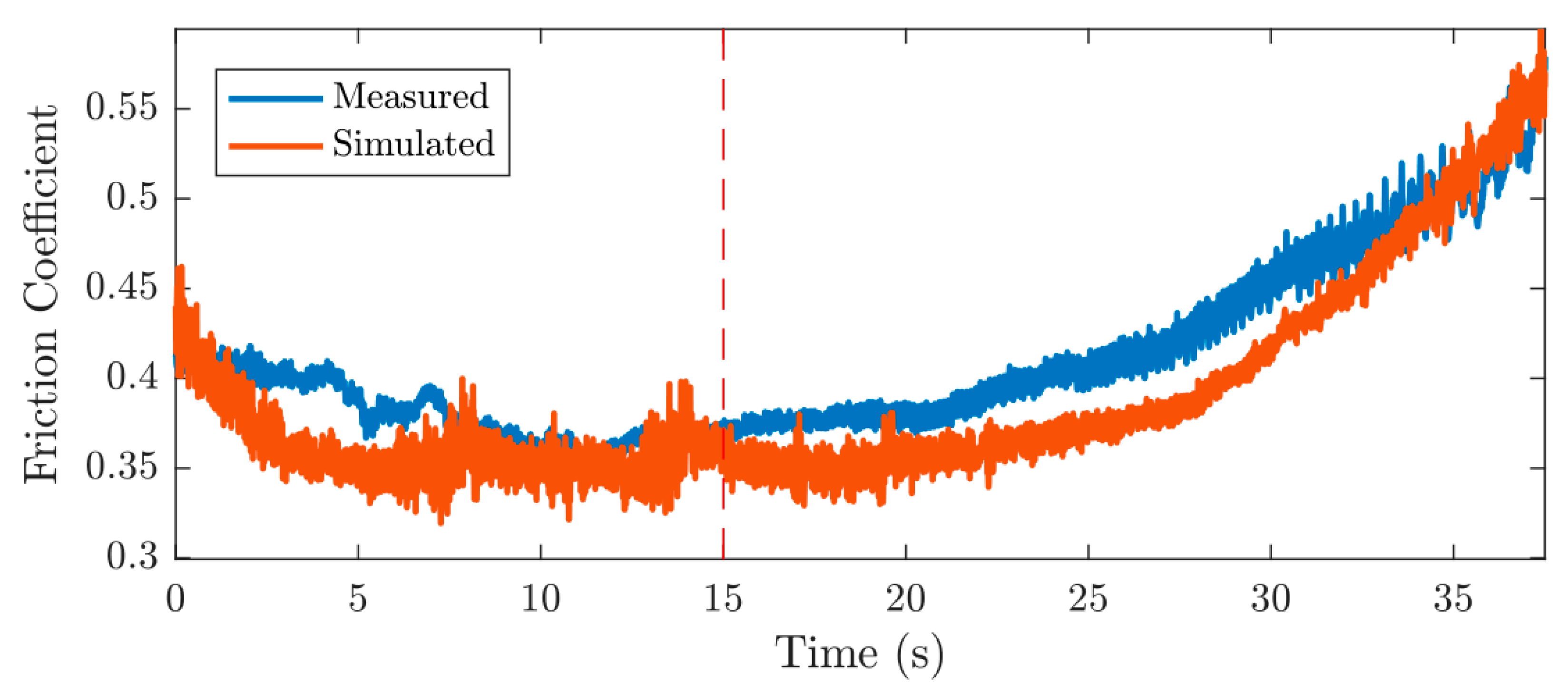
In Figure 12, a measurement application is compared with simulation results from the Abstract Cellular Automaton. In the first 15 seconds of both the measured and simulated brake applications, a constant sliding speed of is imposed. Starting at , a linear velocity ramp is imposed until a sliding speed of is reached. It can be observed that the overall dynamics of the coefficient of friction during a stop braking application are well represented by the Abstract Cellular Automaton.
The increased variation in the coefficient of friction at the end of the measurement is due to the effects of axial run-out of the disc at low speeds. The Abstract Cellular Automaton assumes an ideal axial run-out; this effect is therefore not observed in the simulation results. The tribological behavior simulated using the Abstract Cellular Automaton was also validated against results from a classical grid-based automaton, which itself underwent rigorous validation testing [13].
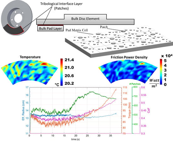
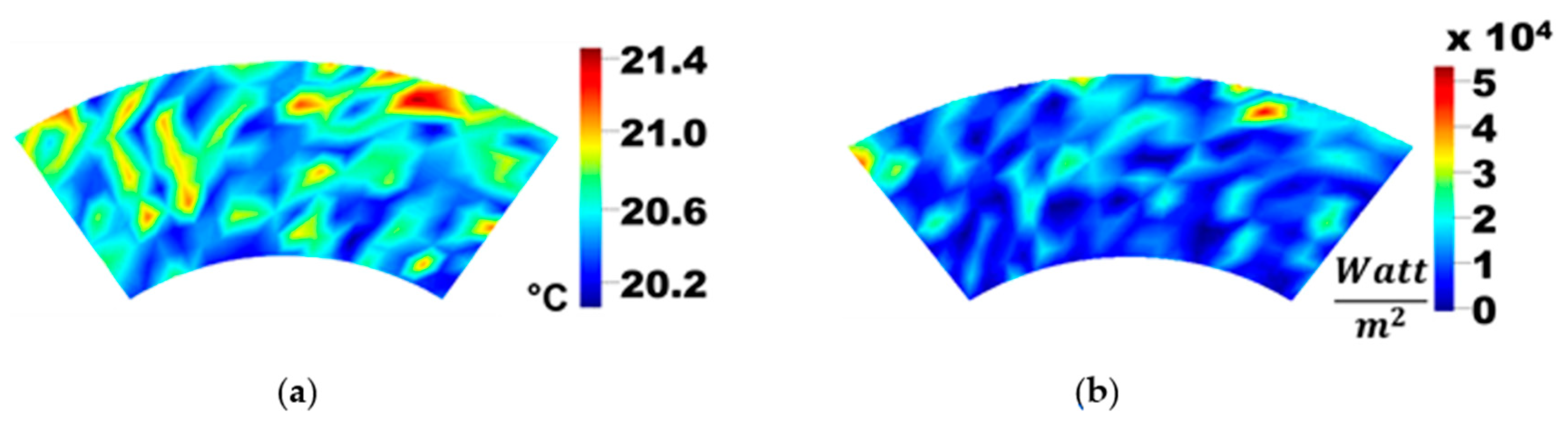
As the Abstract Cellular Automaton simulates tribological boundary layers representing the full surface area of a brake pad, broader spatial effects can be investigated, such as thermoelastic instabilities, friction power distribution (towards determination of the effective friction radius), temperature distribution, etc. This is illustrated in Figure 13, which shows results for temperature and friction power density distributions at one time step in an Abstract Cellular Automaton simulation.
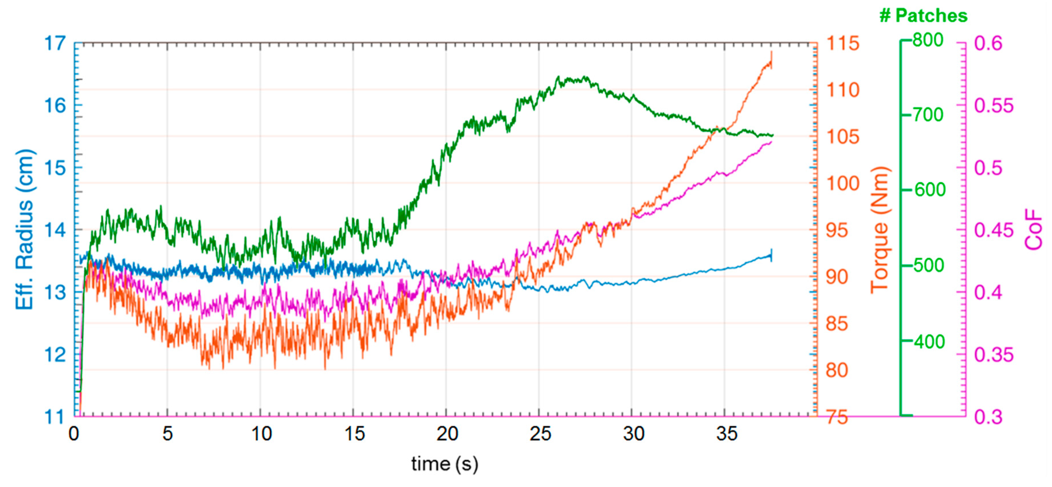
Figure 14 exemplifies the capability of the Abstract Cellular Automaton-based simulations to offer insights into quantities that are difficult to attain through measurements. Typically (for example, on a dynamometer), the total friction torque of a braking system is measured. Here, global values such as the brake line pressure and sliding speed are known, but precise local information, such as the local force distributions and total coefficient of friction at the tribological interface can at best be roughly approximated.
Researchers use data from measurements of the total system torque, with many mechanical components of varying stiffness separating the measurement device from the tribological interface. This dilutes the quality of information for a researcher who is interested in studying fundamental principles in the tribological boundary layer.
Although some new techniques have been developed towards directly measuring the local behavior at the friction interface [18,19], it has been shown that the Abstract Cellular Automaton allows researchers to perform more generalized analyses, considering the unique dynamics of the coefficient of friction and the effective friction radius [16]. Thus, one has the opportunity to gain more nuanced insights into the interactions between these phenomena, and it is possible to interpret the total braking torque as an emergent combination of these dynamics (Figure 14). Furthermore, Figure 14 exemplifies the potential for observing the complex interactions between the aforementioned phenomena and the total number of patches in the interface.
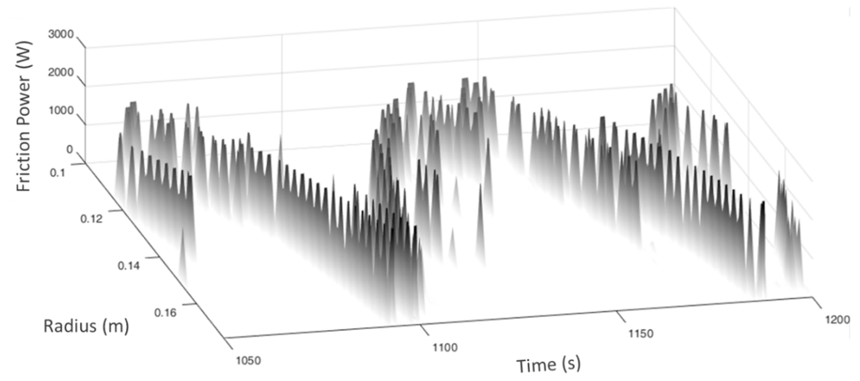
As shown above, the Abstract Cellular Automaton enables considerations of local effects in the tribological interface to be carried out. This capability allows for investigations of thermoelastic instabilities in braking systems. Figure 15 shows the development of the total friction power on the various radii of the tribological interface.
The total sum of the friction power at all patches and all pad matrix cells within each radial section was computed. As seen in Figure 15, the location of maximum friction power oscillates radially along the interface. These studies were carried out using constant normal loading conditions on the brake pad. Realistic, variable normal load development on the pad are also simple to implement.
4. Discussion
The results indicate that complex tribological dynamics can be modeled using 0th order friction rules (Coulomb). More sophisticated friction rules will be introduced for future studies investigating specialized dynamic phenomena such as boundary layer vibrations.
The behavior observed in Figure 15 can be explained as follows: one section, , of the brake pad may encompass more patches than the other section, . The increased presence of patches in this section causes increases in the friction power, and thereby the temperature of . Through thermal expansion, this leads to an increased normal load relative to . This, in turn, encourages more patch birth and growth on . Due to the chosen friction rule, now carries the majority of the friction power in the system. This process continues until it reaches a critical point, when (for example) the load on the patches in causes the collapse of several patches. Many patches in reach the end of their lifetimes and the matrix material of section becomes more vulnerable to wear. The total normal loads on both sections begin to balance as their effective heights (considering wear and thermal expansion) become level. The resulting increasing normal force on causes an increase in the friction force, leading to an increase in temperature, all of which leads to more patch growth and birth in . Thus, the process repeats, and the maximum friction power is then either transmitted back to or on to further radial sections, such as and above.
The resulting dynamics reveal an oscillation with a period in the range of about , depending on how many radii are involved. This phenomenon is suggestive of thermoelastic instabilities (such as hot banding) commonly observed in brake systems. The oscillation periods observed in these simulations correspond to measured thermoelastic instabilities [20,21] and simulation results from established models [11,22].
5. Conclusions
In this paper, the new Abstract Cellular Automaton simulation tool towards modeling the tribological behavior in the boundary layer of automotive brake contacts was introduced. Its fundamental functionality was discussed and it was compared to classical simulation techniques with regard to performance and usage potentials. First results were presented, showing the potential of the Abstract Cellular Automaton to aid investigations of the interactions of various fundamental phenomena that affect braking behavior. The modular structure of the source code makes the Abstract Cellular Automaton versatile for further enhancements and development.
In future investigations, high- and low-frequency synchronized vibration of patches in the tribological interface will be presented. These synchronized vibrations will be related to known NVH phenomena in brake systems, i.e., brake squealing, as discussed in Ref. [12,17]. Such studies will include simulative representations of industry standard NVH studies (such as SAE J2521) and will be carried out using a multi-time scale approach.
Also, the numerical performance is being developed towards the integration of this model into realistic three-dimensional brake models. Here, the dynamics of the brake system are considered together with a confirmed wear debris output model.
Finally, material aspects in the automaton will be confirmed, in order to model dissipation dynamics as is done with the grid-based automaton.
Author Contributions
Georg-Peter Ostermeyer developed the abstract cellular automaton and conceived the simulation program; Georg-Peter Ostermeyer and Joshua H. Merlis authored the source code; Georg-Peter Ostermeyer conceived and designed the simulations and experiments; Joshua H. Merlis performed the simulations and experiments; Joshua H. Merlis analyzed the data; Georg-Peter Ostermeyer and Joshua H. Merlis wrote the paper.
Funding
This research received no external funding.
Acknowledgments
This research received no external funding.
Conflicts of Interest
The authors declare no conflict of interest.
Nomenclature
| Greek Symbols | ||
| Unloaded distance | (m) | |
| Change | (1) | |
| Simulation time step | (s) | |
| Model parameter constant | (1) | |
| Coefficient of friction | (1) | |
| Angular velocity | (rad/s) | |
| Density | (kg/m3) | |
| Roman Symbols | ||
| Surface area | (m2) | |
| Number of pad matrix cells | (1) | |
| Simulation constant/parameter | (1) | |
| Thickness | (m) | |
| Force | (N) | |
| Function of | (1) | |
| Patch height | (m) | |
| Arbitrary indices | (1) | |
| Spring constant factor | (N/m2) | |
| Equivalent spring stiffness | (N/m) | |
| Normal force | (N) | |
| Total number of patches | (1) | |
| Patch | (1) | |
| Iteration indices | (1) | |
| Radius | (m) | |
| Brake pad section | (1) | |
| Time | (s) | |
| Temperature | (°C) | |
| Average sliding speed between the pad and the disc | (m/s) | |
| Wear particle volume in the boundary layer | (m3) | |
| Average brake pad width | (m) | |
| Subscripts | ||
| Patch birth | ||
| Coupled | ||
| Patch collapse | ||
| Friction | ||
| Maximum (allowed) value | ||
| Normal | ||
| Patch | ||
| Brake pad, pad matrix material | ||
| Relative | ||
| Total | ||
| Tangential (parallel to friction) | ||
References
- Gramstat, S. Methoden der in-situ Visualisierung der Reibzonendynamik trockenlaufender Reibpaarungen unter Ergänzung physikalischer und chemischer Charakterisierungen der Reibpartner. Ph.D. Thesis, TU Ilmenau, Ilmenau, Germany, 2015. [Google Scholar]
- Ostermeyer, G.P.; Perzborn, N. Test-Variability of Tribological Measurements. In Proceedings of the SAE 2012 Brake Colloquium & Exhibition–30th Annual, San Diego, CA, USA, 23–26 September 2012. [Google Scholar]
- Ostermeyer, G.P.; Schramm, T.; Raczek, S.; Bubser, F.; Perzborn, N. The Automated Universal Tribotester. In Proceedings of the EuroBrake Conference, Dresden, Germany, 4–6 May 2015. [Google Scholar]
- Perzborn, N.; Agudelo, C.; Ostermeyer, G.P. On Similarities and Differences of Measurements on Inertia Dynamometer and Scale Testing Tribometer for Friction Coefficient Evaluation. SAE Inter. J. Mater. Manuf. 2014, 8, 104–117. [Google Scholar] [CrossRef]
- Eriksson, M.; Jacobson, S. Tribological surfaces of organic brake pads. Tribol. Inter. 2000, 33, 817–827. [Google Scholar] [CrossRef]
- Ostermeyer, G.P. Friction and wear of brake systems. Forsch. Im Ing. 2001, 66, 267–272. [Google Scholar] [CrossRef]
- Müller, M.; Ostermeyer, G.P.; Graf, M. Towards an explicit computation of wear in brake materials. In Proceedings of the SAE 2009 Brake Colloquium and Exhibition, Tampa, FL, USA, 11–14 October 2009. [Google Scholar]
- Ostermeyer, G.P. On the dynamics of the friction coefficient. Wear 2003, 254, 852–858. [Google Scholar] [CrossRef]
- Ostermeyer, G.P.; Müller, M. New developments of friction models in brake systems. Available online: https://www.sae.org/publications/technical-papers/content/2005-01-3942/ (accessed on 2 May 2018).
- Bode, K.; Ostermeyer, G.P. Thermal Effects in Friction Materials-A Comprehensive Strategy for Modeling and Simulation. SAE Inter. J. Mater. Manuf. 2013, 6, 1–10. [Google Scholar] [CrossRef]
- Ostermeyer, G.P.; Graf, M. Influence of wear on thermoelastic instabilities in automotive brakes. Wear 2013, 308, 113–120. [Google Scholar] [CrossRef]
- Ostermeyer, G.P. On Tangential Friction Induced Vibrations in Brake Systems. Springer: Berlin, Germany, 2008; 101–111. [Google Scholar]
- Ostermeyer, G.-P.; Merlis, J.H. Effective Simulation of the Boundary Layer of an Entire Brake Pad. In Proceedings of the SAE Brake Colloquium & Exhibition–33rd Annual, Charleston, SC, USA, 4–7 October 2015. [Google Scholar]
- Bode, K.; Ostermeyer, G.P. A comprehensive approach for the simulation of heat and heat-induced phenomena in friction materials. Wear 2014, 311, 47–56. [Google Scholar] [CrossRef]
- Ostermeyer, G.P.; Dilnot, A.; Lange, J. Analysis of Friction in Brakes on a Virtual AK-Master Test Rig. In Proceedings of the Internationales My-Symposium Bremsen-Fachtagung, Bad Neuenahr, Germany, 26–27 November 2012; pp. 168–182. [Google Scholar]
- Ostermeyer, G.P.; Merlis, J.H. Investigations of the Effective Friction Radius in Simulations of the Boundary Layer of an Entire Brake Pad. In Proceedings of the Eurobrake 2016, Milan, Italy, 13–15 June 2016. [Google Scholar]
- Ostermeyer, G.P. Dynamic friction laws and their impact on friction induced vibrations. In Proceedings of the SAE 2010 Annual Brake Colloquium and Engineering Display, Phoenix, AZ, USA, 10–13 October 2010. [Google Scholar]
- Degenstein, T.D. Kraftmessung in Scheibenbremsen. Ph.D. Thesis, TU Darmstadt, Dissertation, Germany, 2007. [Google Scholar]
- Neis, P.D.; Duarte, F.L.; Perez, D.; Yeczain, F.; Ney, F.; DeBaets, P. Methodology for Determination of the Effective Radius by means of Thermograph Analysis on the Disc Surface. In Proceedings of the EuroBrake 2012, Dresden, Germany, 16–18 April 2012. [Google Scholar]
- Lee, K.; Barber, J. An experimental investigation of frictionally-excited thermoelastic instability in automotive disk brakes under a drag brake application. J. Tribol. 1994, 116, 409–414. [Google Scholar] [CrossRef]
- Severin, D.; Dörsch, S. Friction mechanism in industrial brakes. Wear 2001, 429, 771–779. [Google Scholar] [CrossRef]
- Ostermeyer, G.P.; Müller, M. Dynamic interaction of friction and surface topography in brake systems. Tribol. Inter. 2006, 39, 370–380. [Google Scholar] [CrossRef]
Figure 1.
Graphic representation of patch dynamics, adapted from Ref. [6].
Figure 1.
Graphic representation of patch dynamics, adapted from Ref. [6].

Figure 2.
Magnified brake pad boundary layer with patches: (a) brake pad sample with visible patches (dark spots). Brightness and contrast are adjusted to make the patches more clearly visible; (b) reflection electron microscope (REM) image of a brake pad showing a patch, adapted from Ref. [6]; (c) screenshot from a classic grid-based cellular, adapted from Ref. [7]. The arrow points in the direction of motion of the brake disc for all images.

Figure 3.
Overview of the Abstract Cellular Automaton’s multi-layer model.

Figure 4.
Diagram of pad section as considered in the Abstract Cellular Automaton.

Figure 5.
Flow of influence between the primary components of the Abstract Cellular Automaton.

Figure 6.
Patch birth algorithm flow chart.

Figure 7.
Patch growth algorithm flow chart.

Figure 8.
Patch collapse algorithm flow chart.

Figure 9.
Brake pad elasticity models: (a) diagram of a small section of a brake pad; (b) discretization from grid-based cellular automata; (c) lumped elasticity model of grid-based cellular automata; (d) lumped elasticity model of an Abstract Cellular Automaton.
Figure 9.
Brake pad elasticity models: (a) diagram of a small section of a brake pad; (b) discretization from grid-based cellular automata; (c) lumped elasticity model of grid-based cellular automata; (d) lumped elasticity model of an Abstract Cellular Automaton.

Figure 10.
Schematic drawings of the elastic coupling model: (a) schematic of pad section with unloaded patches; (b): schematic with loaded patches and tangential springs shown.
Figure 10.
Schematic drawings of the elastic coupling model: (a) schematic of pad section with unloaded patches; (b): schematic with loaded patches and tangential springs shown.

Figure 11.
FEM results for patch stiffness with curve fit: (a) in the direction of normal pressure; (b) in the direction of friction; (c) detailed view of (a); (d) detailed view of (b).
Figure 11.
FEM results for patch stiffness with curve fit: (a) in the direction of normal pressure; (b) in the direction of friction; (c) detailed view of (a); (d) detailed view of (b).

Figure 12.
Example measurement results for comparison with Abstract Cellular Automaton-based stop braking results. Deceleration begins at .
Figure 12.
Example measurement results for comparison with Abstract Cellular Automaton-based stop braking results. Deceleration begins at .

Figure 13.
Abstract Cellular Automaton example simulation results: (a) temperature distribution; (b) friction power density distribution [16].
Figure 13.
Abstract Cellular Automaton example simulation results: (a) temperature distribution; (b) friction power density distribution [16].

Figure 14.
Abstract Cellular Automaton example simulation results: Abstract Cellular Automaton enables analyses of the interactions between immeasurable quantities, adapted from Ref. [16].
Figure 14.
Abstract Cellular Automaton example simulation results: Abstract Cellular Automaton enables analyses of the interactions between immeasurable quantities, adapted from Ref. [16].

Figure 15.
Abstract Cellular Automaton example simulation results: indicative of thermoelastic instabilities.
Figure 15.
Abstract Cellular Automaton example simulation results: indicative of thermoelastic instabilities.

© 2018 by the authors. Licensee MDPI, Basel, Switzerland. This article is an open access article distributed under the terms and conditions of the Creative Commons Attribution (CC BY) license (http://creativecommons.org/licenses/by/4.0/).
Share and Cite
MDPI and ACS Style
Ostermeyer, G.-P.; Merlis, J.H. Modeling the Friction Boundary Layer of an Entire Brake Pad with an Abstract Cellular Automaton. Lubricants 2018, 6, 44. https://doi.org/10.3390/lubricants6020044
AMA Style
Ostermeyer G-P, Merlis JH. Modeling the Friction Boundary Layer of an Entire Brake Pad with an Abstract Cellular Automaton. Lubricants. 2018; 6(2):44. https://doi.org/10.3390/lubricants6020044
Chicago/Turabian StyleOstermeyer, Georg-Peter, and Joshua H. Merlis. 2018. "Modeling the Friction Boundary Layer of an Entire Brake Pad with an Abstract Cellular Automaton" Lubricants 6, no. 2: 44. https://doi.org/10.3390/lubricants6020044
Note that from the first issue of 2016, this journal uses article numbers instead of page numbers. See further details here.