Article

Thermal–Hydrodynamic Behaviour of Coated Pivoted Pad Thrust Bearings: Comparison between Babbitt, PTFE and DLC

by
Konstantinos Katsaros
1,
Dimitrios A. Bompos
1,
Pantelis G. Nikolakopoulos
1,* and
Stephanos Theodossiades
2
1
Machine Design Laboratory, Department of Mechanical Engineering and Aeronautics, University of Patras, 26500 Patras, Greece
2
Wolfson School of Mechanical, Electrical and Manufacturing Engineering, Loughborough University, Loughborough, Leicestershire LE11 3TU, UK
*
Author to whom correspondence should be addressed.
Lubricants 2018, 6(2), 50; https://doi.org/10.3390/lubricants6020050
Submission received: 25 December 2017 / Revised: 4 May 2018 / Accepted: 8 May 2018 / Published: 17 May 2018
(This article belongs to the Special Issue Friction and Lubrication of Sliding Bearings)

Abstract

:
The hydrodynamic lubrication and thermal analysis of tilting pad thrust bearings has been a major subject for many studies in the field of tribology. There is only a limited number of studies regarding thrust bearings with coated surfaces. The purpose of this study is to build a parametric, iterative algorithm in order to perform a complete thermal and hydrodynamic lubrication analysis for pivoted pad thrust bearings with coatings. The analytical model is mainly based on the energy, continuity and Navier–Stokes equations, which are solved numerically with the Semi-Implicit Method for Pressure Linked Equations Consistent (SIMPLEC) method. The analysis focuses on a single pivoted pad of the thrust bearing. The thermal properties of the coating material are taken into account and the resulting thermal and flow fields are solved. The basic hydrodynamic and tribological characteristics are calculated for an uncoated, a Babbitt coated, a PTFE coated and a diamond like carbon (DLC) coated pivoted pad thrust bearing. The pressure and the film thickness distribution, as well as the load capacity and the frictional forces, are determined for several pad positions and velocities of the rotor. A mineral oil lubricant is used to estimate the shear thinning or thickening effects on the pad tribological performance. The results indicate that pads coated with PTFE and DLC show lower friction forces compared to the common steel and Babbitt applications. At the same time, the DLC coating seems to affect the bearing’s flow and thermal fields less than the PTFE, making it more suitable for thrust bearings applications.

1. Introduction

Hydrodynamic thrust bearings are commonly used in rotating machinery. An oil film between two sliding surfaces is essential to limit wear and to enhance bearing performance. Hydrodynamic lubrication relies on the convergent wedge and the relative motion of the two surfaces together with the viscous nature of the lubricating oil. Nowadays, and due to technological progress, pad thrust bearings are one of the most essential components of many industrial, commercial and naval applications determining the reliability of the whole operation. Thrust bearings of large vertical shaft power units take thrusts up to several hundred and in some cases even several thousand tons. The expectation is that they become compact in size and work for higher load carrying capacity. At the same time, environmental and economic concerns require that pad thrust bearings must operate with minimum power loss. Thus, various design improvements such as different surface profiles, texturing and coatings over pads’ surfaces are carried out in order to enhance the bearing performance. There are significant problems to be solved regarding the design and especially the operation of thrust bearings under nominal thrusts resulting from thermal and mechanical deformations of the segments. To start with, these problems are associated with the transient modes, i.e., start-up and stop of the power unit. Thermohydrodynamic analysis of tilting pad thrust bearings is an important topic in the science of tribology [1,2,3]. Moreover, high temperatures and pressures due to misalignment or cavitation issues can also cause major impacts [4,5]. In many investigations [1,2,3,6,7,8], the performance of hydrodynamic pad thrust bearings has been studied, taking into consideration the influence of temperature on the viscosity of the lubricant. Khonsari [9] and Tanaka [10] presented detailed review papers on thermal–hydrodynamic (THD) analyses of fluid film bearings.
Surface coatings have been the main concern for many researchers. Tailoring friction properties of lubricated contacts operating under the elasto–hydrodynamic (EHD) lubrication regime have recently come to the forefront, especially in terms of reducing viscous friction (that governs friction performance in those types of contact) [11,12,13,14]. A series of tests were also carried out including different types of DLC coatings deposited on surfaces with different roughness, as well as different types of lubricants and varying contact properties (load, slide-to-roll ratio) [13]. Researchers have compared Babbitt coatings with polymer ones (such as PTFE and PFA) in terms of hydrodynamic as well as thermal performance [15,16,17,18]. Tailoring friction properties of lubricated contacts with DLC coating have been presented in [19] for the case of thrust bearings. The results show that the (H-DLC) coatings provide excellent wear resistance and low friction for bearing applications. However, the use of such coatings with aqueous lubricants could pose some difficulties due to the hydrophobic nature of the surface.
The TEHD (thermo–elasto–hydrodynamic) analysis is able to give more accurate results regarding the overall behavior of the bearing [20,21] in cases where either the coating or the bearing material itself is significantly deformed. As a result of the higher elasticity of the sliding layer in the case of softer materials such as PTFE, the load distribution can become greater even among individual pads of the bearing. For example, the elasticity of the bearing faces can entrap oil in the loaded area, helping in such way the cases of lubricant misfeeding or offering excellent anti-seizure properties [22]. TEHD (thermo–elasto–hydrodynamic) bearing models were used by Glavatskih and Fillon [20]. The results of theoretical analyses for PTFE-faced tilting-pad thrust bearing were presented. For comparison purposes, analyses were also carried out for Babbitt-faced bearings of the same size. Glavatskih and Fillon presented the solution of the generalized Reynolds equation which permits taking into account fluid flow, thermal phenomena in the oil film, heat transfer, thermo-elastic pad deformations, and pad tilting. Also, they showed that the minimum film thickness deviates slightly between the two bearing types (PTFE and Babbitt coated), with the film thickness of the inlet being 96 micrometers for the Babbitt coating and 82 micrometers for the case of the PTFE coating. Regarding the power losses, it was noticed that they were slightly lower for PTFE lined bearings. However, bearing performance also depends on shaft speed. Power losses calculated at low velocities were comparable for both bearing types. Ettles et al. [21] mentions that there is strong interest in the industry concerning PTFE and Babbitt coated bearings, but limited data are available on actual performance. They also mentioned that the power losses for the two types of bearing coatings were found to be almost identical. Also, effects such creep of materials were observed and discussed. The test results are compared with predictions using the GENMAT analysis software. A method of allowing for creep in numerical modelling was also discussed. Bálint et al. [22] presented an experimental study as well as a THD and pseudo-transient TEHD simulation in order to examine the seizure of the PTFE in grooved journal bearings during start up.
In this work, the thermo-hydrodynamic behavior of pivoted pad thrust bearings treated with DLC, Babbitt, and PTFE faced materials is accomplished using a combined THD FEM and CFD model.
The calculations performed in this work showed that the DLC coating offers the best possible option between those examined, since its mechanical and thermal properties improve the operational characteristics of the thrust bearing. Combined with the anti-wear properties at mixed and boundary lubrication conditions, this specific coating option is suggested for further investigation in different bearing applications.

2. Theory

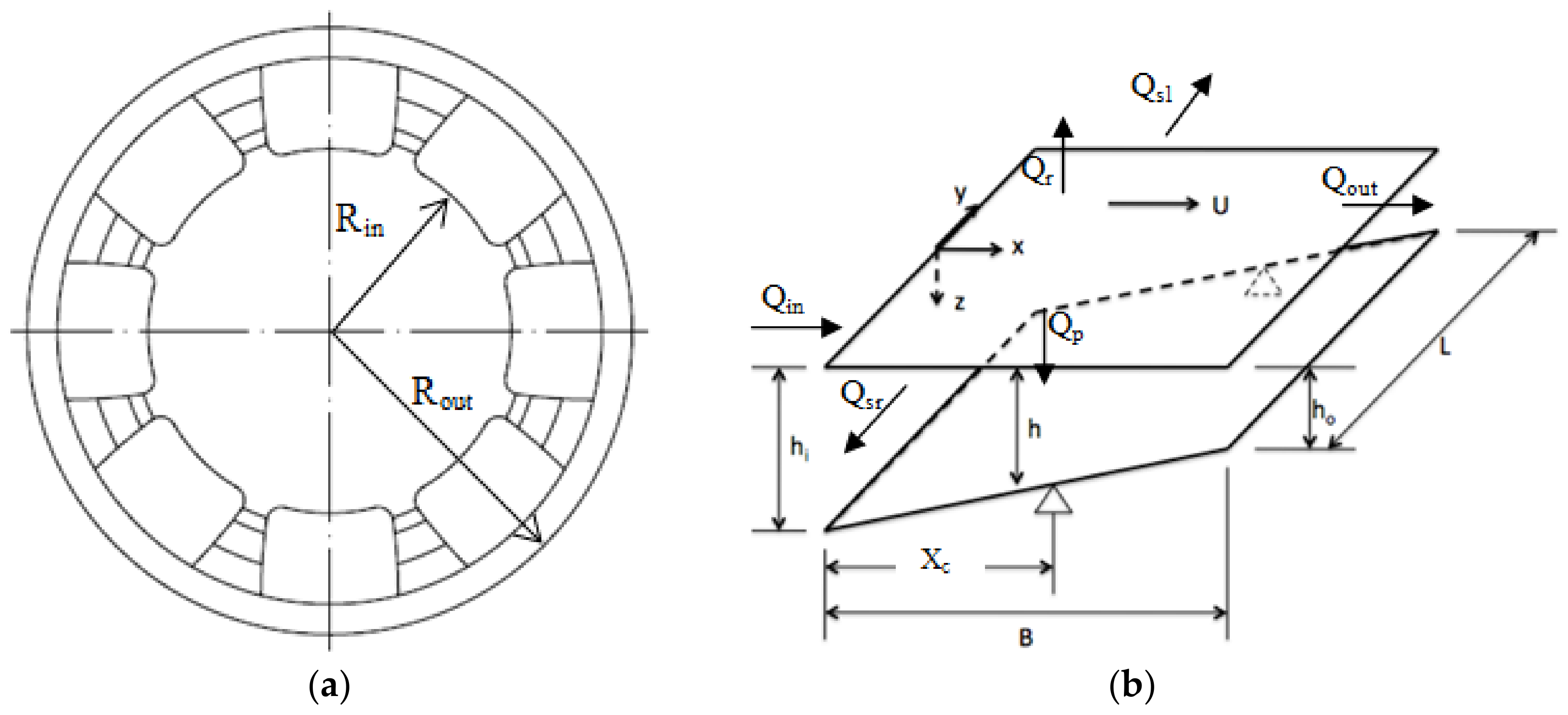
2.1. Hydrodynamic Analysis

Governing Equations and Assumptions

The flow is considered non-isothermal and the minimum pressure value is assumed to be above the vapour pressure; thus, cavitation is not accounted for.
The usual assumption of hydrodynamic bearings lubrication is the no-slip assumption at the wall, leading to the oil layer having the same velocity as the solid surface that it comes into contact with. Slip can occur when the solid surface is smooth enough and the oil is under relatively high shear stress [23]. In the topic examined in the current work, it is expected that the possible bearing surface deformations due to hydrodynamic and thermal loads will “forbid” lubricant to escape, helping the better wetting of the solid, supporting the assumption of the lack of slip at the wall. A typical view of a pivoted pad thrust bearing is presented in Figure 1.
The conservation equations for unsteady incompressible and isothermal flow, with zero gravitational and other external body forces, are as follows:
Mass conservation equation
V = 0
Momentum equation
V t + V V = 1 ρ p + μ ρ 2 V
Equations (1) and (2) are solved with the CFD commercial code ANSYS Multiphysics v14. From dimensional analysis, it follows that, for a given geometry, the flow dynamics depend on the Reynolds number, Re, defined here in the bearing mid-section in terms of the moving wall velocity, U, and the minimum film thickness, Hmin. Simulations are performed for Re = 14, 10.8, 7.8, 4.7, 1.6. In the present dimensional model, a value of Re = 7.8 corresponds to a wall velocity U = 24.34 m/s (in the pad mid-sector) and values of the fluid thermo-physical properties equal to those of oil at 25 °C.

2.2. Thermal Analysis

In order to obtain the pressure, velocity and temperature distribution in the volume of the thin fluid film, computational fluid dynamics (CFD) analysis is performed. The fluid film is meshed using 3D 8-node hexahedron elements with 5 degrees of freedom at each node, the velocities Vx, Vy and Vz along the x, y and z directions of the global coordinate system respectively, the total pressure and the nodal temperature T. Certain boundary conditions, presented in Section 3 of the manuscript, are applied on the CFD model in order to accurately approximate to the actual problem.

Energy Equation

The energy equations for a laminar flow with viscosity model following Equations (1) and (2) for the lubrication of an infinitely wide slider bearing can be written as below:
t ( ρ C p T ) + x ( ρ V x C p T ) + y ( ρ V y C p T ) + z ( ρ V z C p T ) = x ( K T x ) + y ( K T y ) + z ( K T z ) + Q V
where QV is a term that represents internal heat sources that may raise the lubricant’s temperature. In the case studied, it is assumed that no such heat sources exist; thus, the term is not accounted for.

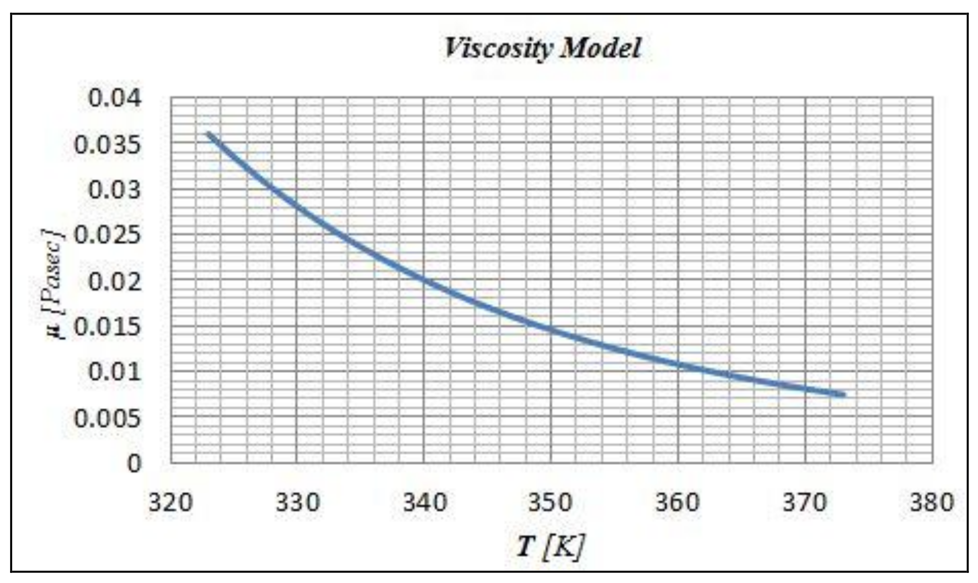
2.3. Viscosity Model

The viscosity variation with respect to temperature is modelled according to Sutherland’s law, see Equations (4) and (5) and Figure 2. Specific coefficients have been calculated in order to adapt the viscosity model to the needs of the case studied. The lubricant properties used in all cases match those of SAE30 with a density of 890 kg/m3.
μ = μ ν e A
A = C 2 μ ( 1 Τ + 1 C 1 μ ) + C 3 μ ( 1 Τ + 1 C 1 μ )

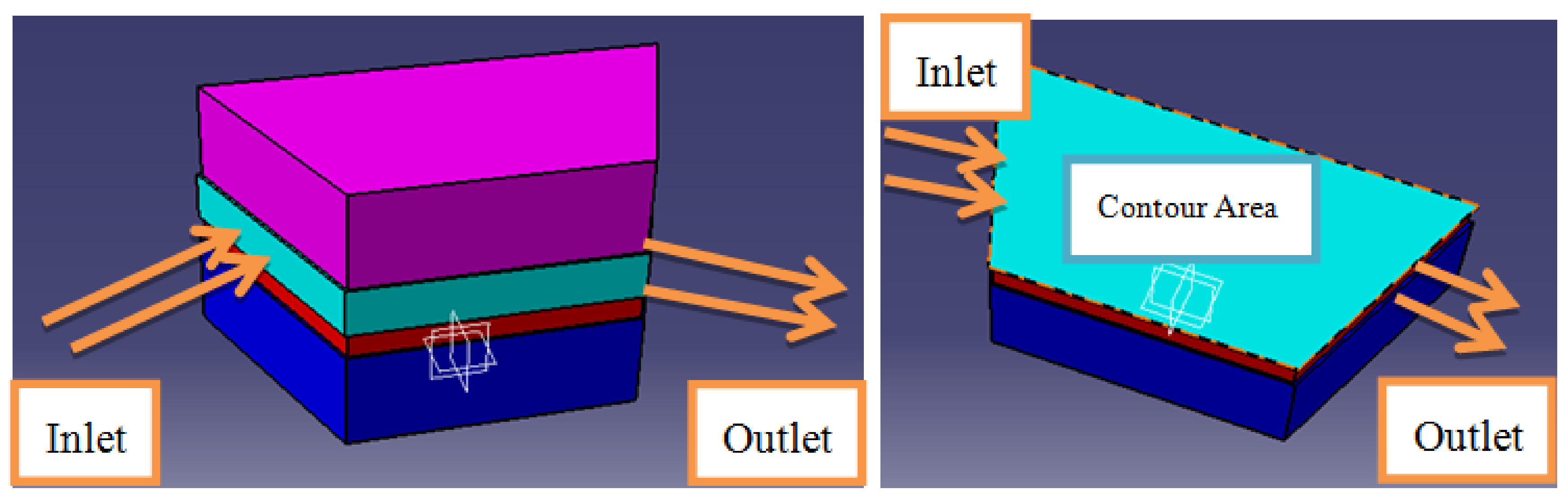
3. Spatial Discretization, Boundary and Initial Conditions

Depending on flow symmetries of the particular case studied, the model was built according to the schematic in Figure 1. The typical 3-D meshes that were generated consisted of approximately 250,000 hexahedral finite volumes per bearing pad. During load variation, since the instantaneous pad height changes, the grid is modified accordingly; the modification maintains the total number of finite volumes. The corresponding finite volume number in the cross-flow direction of the slider is 50, along the z direction. In the radial direction, discretization utilizes a typical finite volume number of approximately 45 elements. Spatial resolution tests have been performed by generating meshes with numbers of finite volumes both lower and substantially higher than the typical meshes used. The relative differences in the flow integral quantities between typical and very fine meshes were in all cases on the order of 1%.
The bearing walls are considered impermeable. The bottom wall is stationary. The upper wall is assumed to be moving at a constant angular velocity, ω , which corresponds to a velocity U = ω R m e a n at the pad mid-sector. No-slip conditions are assumed at both walls.
The inlet and outlet surfaces of the bearing (see Figure 1), are considered openings: the pressure is assumed constant, with the same value p = 0 prescribed at both boundaries. At the bearing sides, r = Rin, Rout, an outflow condition is prescribed, i.e., in addition to the above assumptions, no inflow to the computational domain is allowed and the value of pressure p = 0 is applied.
All simulations were initialized from different velocities of the rotor. The convergence to steady-state conditions was verified by monitoring the computed velocity, temperature and pressure at a number of representative points within the flow domain.
The average vertical force exerted to a pad area is calculated by integrating the instantaneous pressure, p, over the sector pad’s surface:
F p = 1 N p A p d A = W
where A is the total area of the bearing pads.
For the thermal analysis, a constant temperature of Ta = 50 °C (323 K) is assumed in the thrust bearing’s ambient. This temperature is applied in the outer surfaces of the rotor, the lubricant, the coating and the pad.
The heat transfer is governed by the following Laplace’s equation:
( 2 T x 2 ) + ( 2 T y 2 ) + ( 2 T z 2 ) = 0
Boundary conditions at the fluid–ambient, fluid–stationary pad (uncoated bearing), fluid–coating (coated bearing), fluid–rotor, rotor–ambient, stationary pad–ambient, coating–ambient and coating–stationary pad (coated bearing) boundaries are given as:
  • Fluid–ambient inlet surface:
    T ( B , y , z ) = T a
  • Fluid–ambient outlet surface:
    T ( 0 , y , z ) = T a
  • Fluid–ambient Side y = 0 surface:
    T ( x , 0 , z ) = T a
  • Fluid–ambient Side y = L surface:
    T ( x , L , z ) = T a
  • Fluid–coating interface:
    K i ( T i z i ) z i = 0 = h c ( T i ( x , y , 0 ) T j )
  • Fluid–rotor interface:
    K i ( T i z i ) z i = t = h c ( T i ( x , y , t ) T j )
  • Coating, pad, rotor–ambient interfaces for the inlet, outlet and side surfaces:
    K i ( T i y i ) y i = 0 = h c ( T i ( x , 0 , z ) T a )
    K i ( T i y i ) y i = t = h c ( T i ( x , L , z ) T a )
    K i ( T i x i ) x i = 0 = h c ( T i ( 0 , y , z ) T a )
    K i ( T i x i ) x i = t = h c ( T i ( B , L , z ) T a )
  • Pad–coating interface:
    K c ( T c z c ) z c = t c = K s ( T s z s ) z s = 0
    where i = s, r, c, for the cases of the stationary pad, the rotor and the coating layer, j = oil and a = ambient for the case of the lubricant, the ambient temperatures.

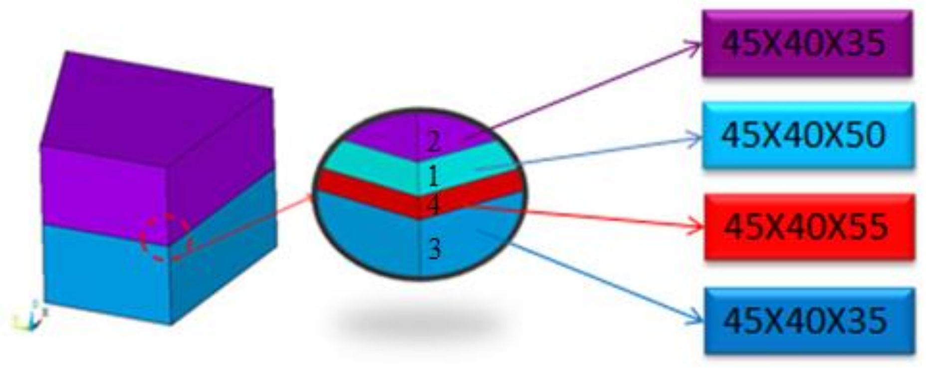
4. Coating Simulation

The geometry for the coating simulation was designed with four volumes. The initial volume, coloured cyan (volume No. 1, Figure 3), corresponded to the lubricant. Two more volumes were added, the first one on top and the second on the bottom of the lubricant that simulated the rotor—coloured magenta (volume No. 2)—and the sector pad of the bearing, coloured dark blue (volume No. 3). Finally, a 6-μm volume was added between the sector pad and the fluid film—coloured red (volume No. 4)—that simulated the thin layer of coating for the current case study. Each volume was meshed separately with its own grid. For the lubricant, a grid of 45 × 40 × 50 elements was used along the x, y and z directions. Similarly, for the coating, the chosen grid consisted of 45 × 40 × 55 elements and for the rotor and pads 45 × 40 × 35 elements were used.

5. Convergence Criteria
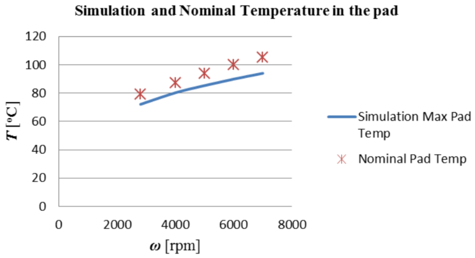
The below convergence criteria were used for the pressure and the temperature:
E r r p r e s s = i = 1 i = N n C F D | p i k p i k 1 | i = 1 i = N n C F D | p i k | 1 × 10 6
E r r T e m p = i = 1 i = N n C F D | T i k T i k 1 | i = 1 i = N n C F D | T i k | 1 × 10 6
A converged solution for the thermo-hydrodynamic problem is obtained when both pressure and temperature criteria are reached simultaneously.

6. Validation

The data (Table 1) for the validation of the model were obtained from the paper of Bielec and Leopard [24]. Figure 4 and Figure 5 show the comparison between the bearing’s pad load and the maximum pad temperature obtained from the present model with the one presented in [24]. The graphical display shows that the results obtained from the present model are in good agreement with the results of the relevant reference.

7. Design Parameters

The friction force is calculated in the equilibrium position by integrating the shear stress τ over the bearing (or journal) area:
F f r i = A i τ   ι d A i , i = j or b
where i = j refers to journal and i = b refers to bearing. Ai is the total area of journal or bearing.
The stress tensor can be defined as
τ ¯ = μ [ ( υ + ( υ ) T ) 2 3 υ I ¯ ¯ ]
where the second term on the right-hand side is the effect of volume dilation and μ is the dynamic viscosity.

8. Results

Results have been recorded for five rotor velocities—1000, 3000, 5000, 7000, 9000 rpm—three pad angles that correspond to three values of the coefficient—k = 0.25, 0.67, 1.54—and three coatings—Babbitt, PTFE and DLC. Different coating manufacturing methods (sintering, casting and vacuum deposition) lead to a variety of coating thicknesses depending on the material applied as a layer. Yet, for comparison purposes only, the coating’s thickness is assumed to be 6 μm in all the studied cases. All properties (Table 2) of the materials studied are presented in the following table [25,26,27,28,29]:

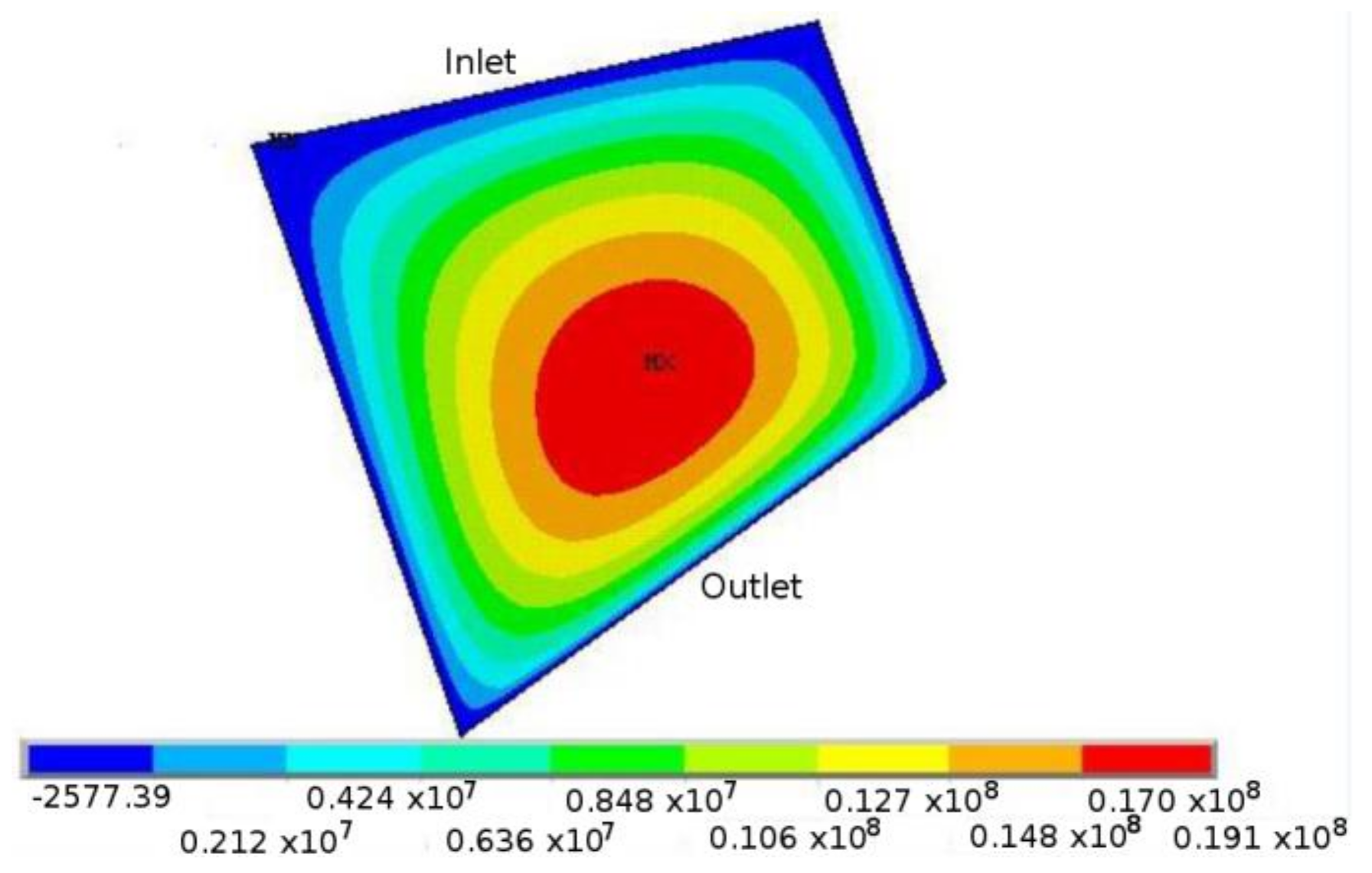
8.1. Hydrodynamic Problem

A 3D representation of the simulated pad as well as the surface, which the following contours refer to, is presented in Figure 6:
The pressure distribution along the oil film can be seen in Figure 7. The maximum pressure can be observed in the centre of the surface and towards the bottom of the image where the minimum film thickness occurs. The distribution is similar in all cases but different pressure values can be observed for different velocities, pad angles or coatings.

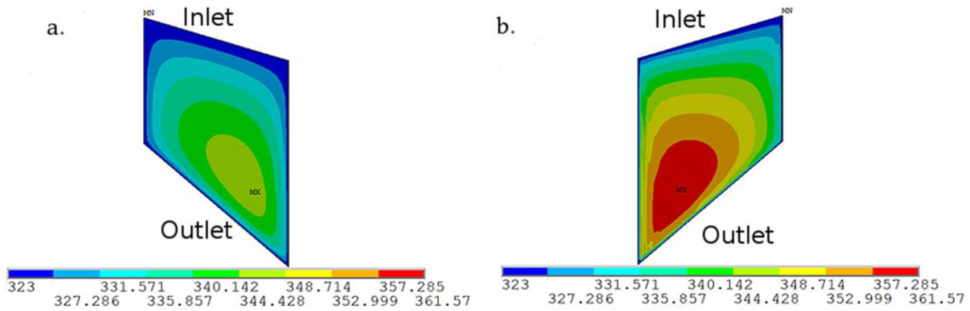
8.2. Thermo-Hydrodynamic Problem

Figure 8 shows the temperature distribution along the oil film. The maximum temperature can be observed near the region of the minimum film thickness and maximum rotating speed. The distribution is similar in all cases but different temperature values can be observed for different velocities, pad angles or coatings.
Figure 9 shows the viscosity distribution for the four cases studied: the uncoated pad, the Babbitt coated pad, the PTFE and the DLC coated pads:
In all cases, the distribution is identical to that of the temperature and according to the viscosity model, since the higher temperatures are observed almost in the centre of the pad and the lower viscosity values are observed in the same area as well. The PTFE that has the lowest thermal conductivity also shows the highest temperatures, and this leads to the PTFE being the material with the lowest viscosity for the same lubricant and the same conditions of operation.

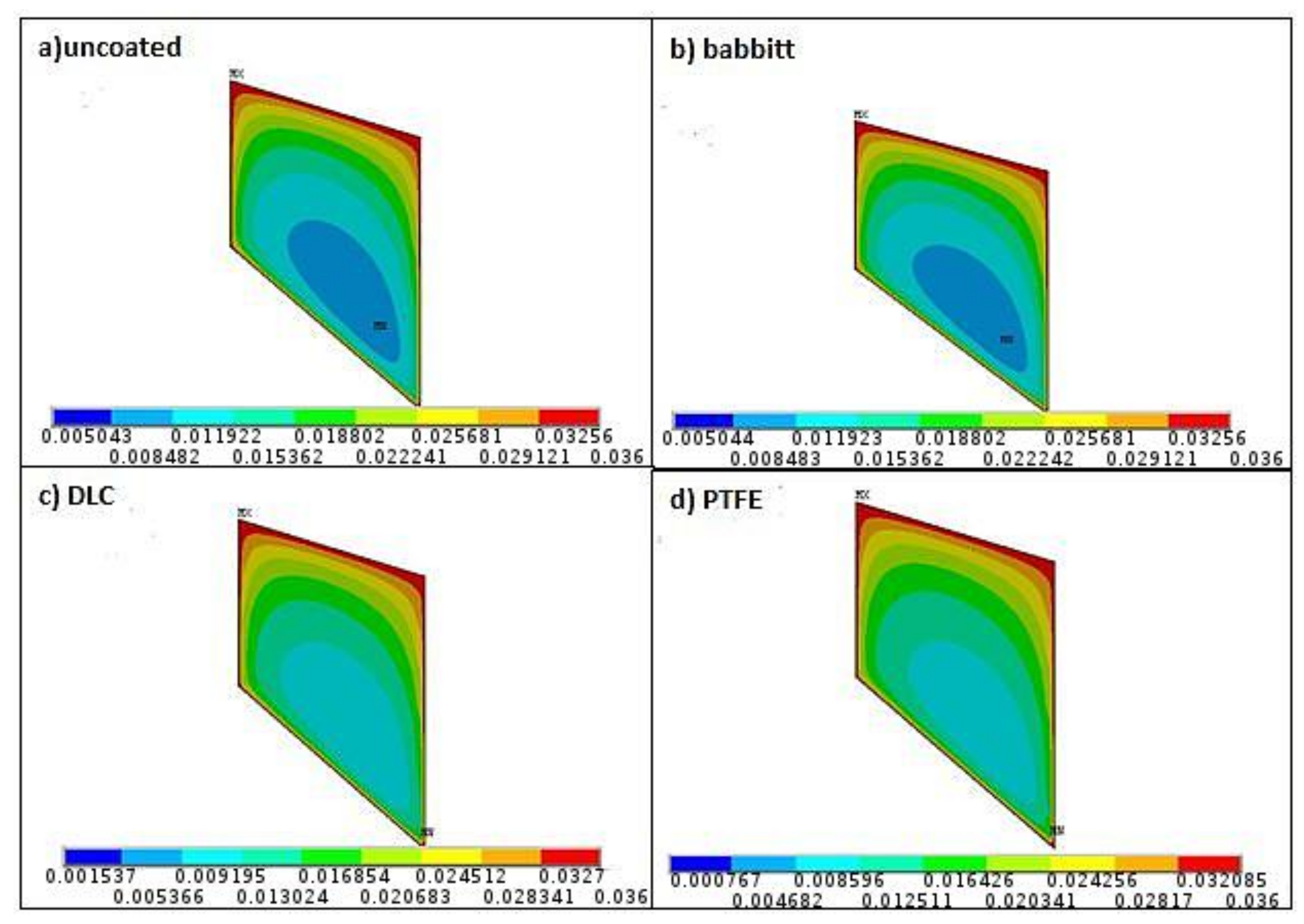
8.3. Thermo-Hydrodynamic Results for the Uncoated and Coated Thrust Bearings

The temperature distribution for the case of the DLC coated pad thrust bearing is shown in Figure 10. Comparing the maximum temperature on the rotor’s side to the one in the pad’s side, a difference up to 20 °C can be observed for 5000 rpm rotor velocity and k = 0.67. Comparing the maximum temperature on the pad’s side for the uncoated pad (Figure 8) to the one of the DLC coated pad, a difference of 4 °C is observed, due to the significantly lower thermal conductivity of the DLC coating.
The following Figure 11, Figure 12, Figure 13, Figure 14, Figure 15, Figure 16, Figure 17, Figure 18, Figure 19, Figure 20, Figure 21, Figure 22, Figure 23, Figure 24, Figure 25 and Figure 26 present the results, in the hydrodynamic and thermal fields, for the DLC, Babbitt and PTFE coated thrust bearings, operating under different conditions, in terms of k values and rotational speeds. In the following discussion, some comparisons between the numerical results obtained for different pad types under specific operating conditions are given in a percent form as examples of the highest observed differences.
In THD analysis, the qualitive behavior of the several examined coating cases seems to be similar, regarding the pressure, the temperature, the friction force and the heat flux through the pad. However, there are a lot of significant quantitative differences that are worth noting for certain operational points.
Figure 11 shows the maximum lubricant pressure in the oil film for the cases of DLC coated and uncoated, steel made pad thrust bearings. At 9000 rpm rotor velocity and k = 0.25, the maximum pressure on the DLC coated pad is up to 2.5% lower than it is on the uncoated pad. Further, Figure 12 shows the maximum lubricant pressure on the oil film for the cases of DLC and the Babbitt coated pad thrust bearings. Here, at 5000 rpm rotor velocity and k = 0.25, the maximum pressure on the DLC coated pad is up to 3% lower than it is on the Babbitt coated pad. Consequentially, Figure 13 shows the maximum lubricant pressure for the cases of DLC and the PTFE coated pad thrust bearings. At 9000 rpm rotor velocity and k = 0.25, the maximum pressure on the DLC coated pad is up to 2.5% higher than on the PTFE coated pad, while in Figure 14 at 9000 rpm rotor velocity and k = 0.25, the maximum pressure on the PTFE coated pad is up to 5% lower than on the Babbitt coated pad.
Regarding the maximum lubricant temperature in the oil film, Figure 15 presents the cases of DLC coated and uncoated pad thrust bearings. At 9000 rpm rotor velocity and k = 1.54, a 9% higher temperature is observed for the DLC coated pad, while in Figure 16 at 9000 rpm rotor velocity and k = 1.54, a 7% lower temperature is observed for the DLC coated pad as compared to the PTFE coated one. Furthermore, in Figure 17, at 9000 rpm rotor velocity and k = 1.54, a 9% higher temperature is observed for the DLC coated pad compared to the Babbitt one, while in Figure 18 at 9000 rpm rotor velocity and k = 1.54, a 15% higher temperature is observed for the PTFE coated compared to that of the Babbitt coated pad.
The pad’s friction force is also a very important parameter in lubrication studies. Figure 19, Figure 20, Figure 21 and Figure 22 present the results for all the examined cases. DLC and PTFE coated pads present lower friction values when compared to steel and Babbitt coating, whereas the PTFE coated pad itself appears to have lower friction values than the DLC coated one for every k value and rotating velocity. The physical mechanism that explains the smaller friction force in every case is the viscosity distribution, presented in Figure 9 for multiple coatings. Lower viscosity values result in lower friction force on the sector pad area since the thrust bearing operates in hydrodynamic lubrication regime. As indicated, at 3000 rpm rotating velocity and k = 1.54, in Figure 19, 1% less friction force can be observed for the case of the DLC coated pad compared to the uncoated steel pad, while at 9000 rpm and k = 0.67, Figure 20, DLC shows 1% less friction force than the Babbitt coating. Moreover, when DLC is compared to PTFE, Figure 21, at 5000 rpm and k = 1.54, 1% higher friction force can be observed for the case of the DLC coated pad.
Another important parameter for evaluating the performance of the different coatings is the heat flux. Figure 23, Figure 24, Figure 25 and Figure 26 show the maximum heat flux from the oil film to the coating layer for the cases of the DLC, Babbitt and PTFE coated and the uncoated pad thrust bearings. An important thing to notice is that the uncoated pad and the Babbitt coated pad show higher values of heat flux in comparison to the DLC and the PTFE coated pads in all cases. For instance, in Figure 23 and Figure 24, at 9000 rpm and k = 1.54, the heat flux is up to 19% lower for the DLC coating. Moreover, Figure 25, at 9000 rpm and k = 1.54, the heat flux is 28% lower for the PTFE coating in comparison to the Babbitt one. Finally, in all cases, the PTFE coated pad shows higher heat flux than does the DLC-coated one. In Figure 26, for example, at 9000 rpm and k = 1.54, 13% higher heat flux can be observed for the case of the DLC coating compared to the PTFE one.
From the above results, it is observed that, as the thermal conductivity of the film decreases from steel to Babbitt (tin based) to DLC and to PTFE (Table 2), the heat flux into the pad also decreases, raising the lubricant’s temperature and consequently the pad’s surface temperature. Therefore, the lubricant’s viscosity decreases, which leads to a lower load capacity for the bearing.

9. Conclusions

For the current case studied, the operation of pivoted coated pad thrust bearings was simulated and the flow and thermal fields were numerically solved for three different coating applications: Babbitt, PTFE and DLC.
The thermo-hydrodynamic simulation enables us to calculate the interdependency between the heat flux through the coatings and the variation of the lubricant’s viscosity. The higher the thermal conductivity of the coating material, the lower the lubricant viscosity, which in turn leads to higher load capacity as well as higher friction and vice versa. The extent of the coatings’ influence is indeed significant given their low thickness. This is something that needs to be considered in the design of a suitable coating surface or during the design of the bearing itself.
The investigation of different pad angles and rotor velocities produced the following results:
The tin-based Babbitt coating has similar properties to steel. As a result, no significant changes were observed for the flow and thermal fields.
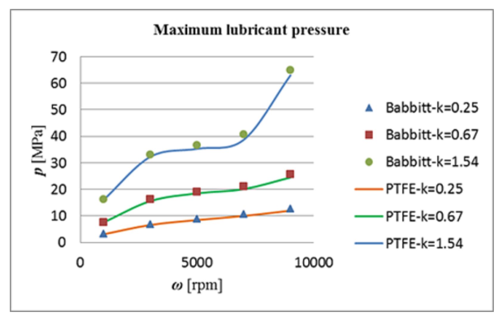
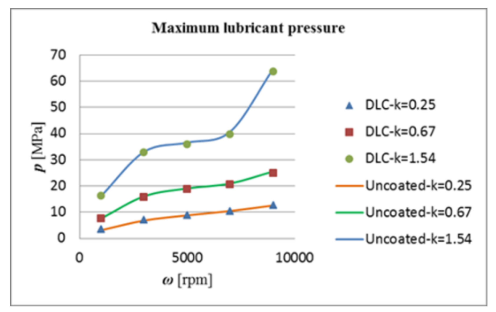
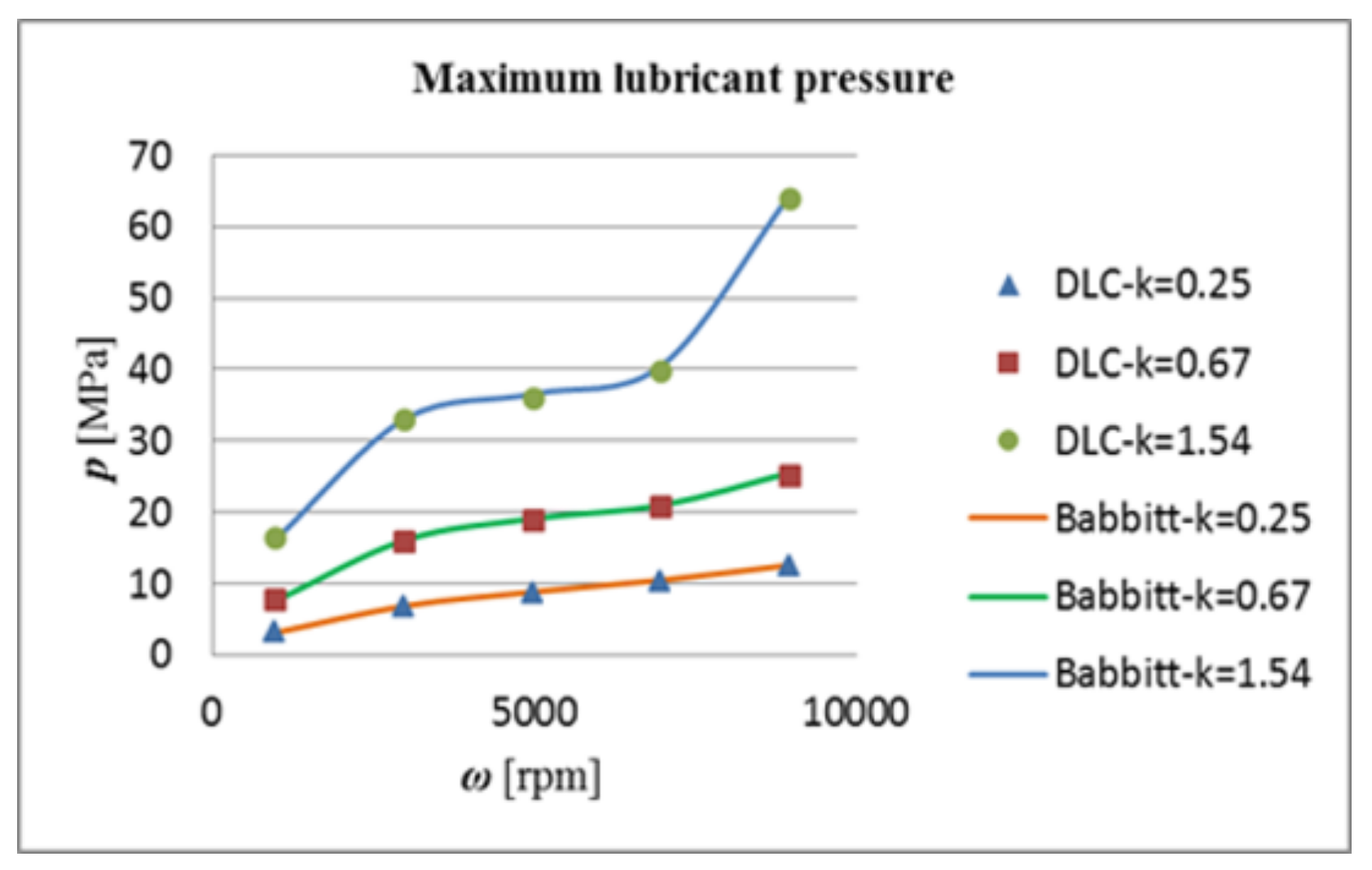
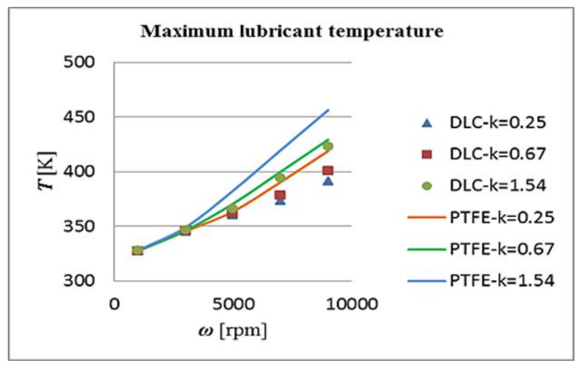
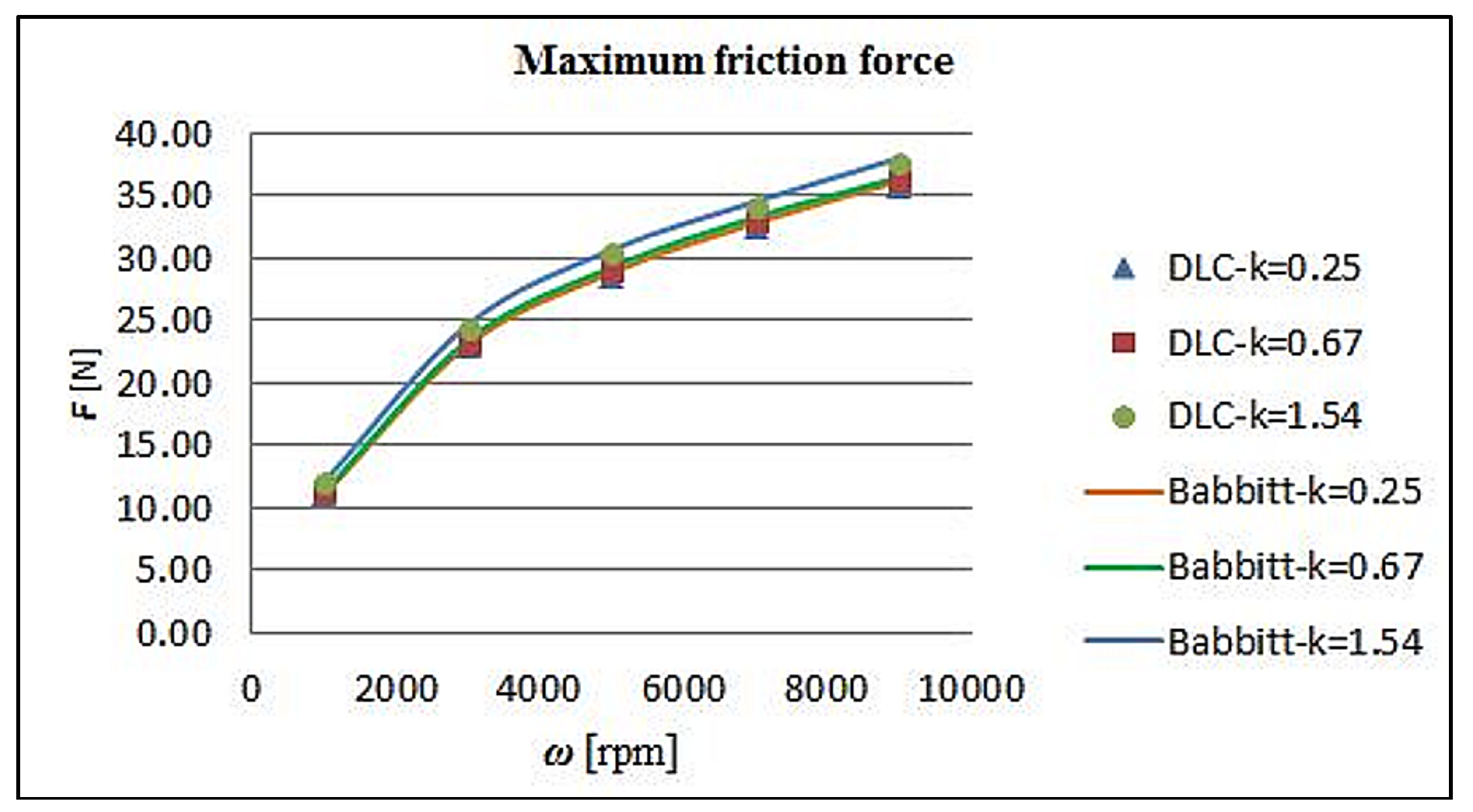
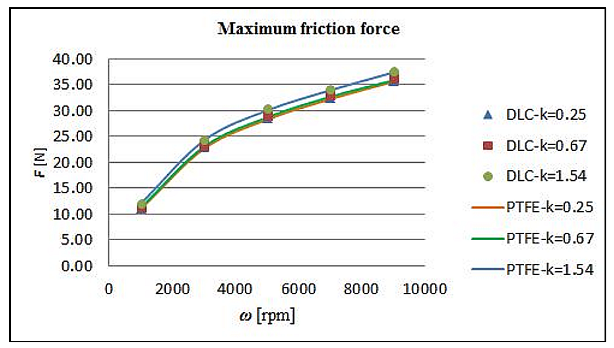
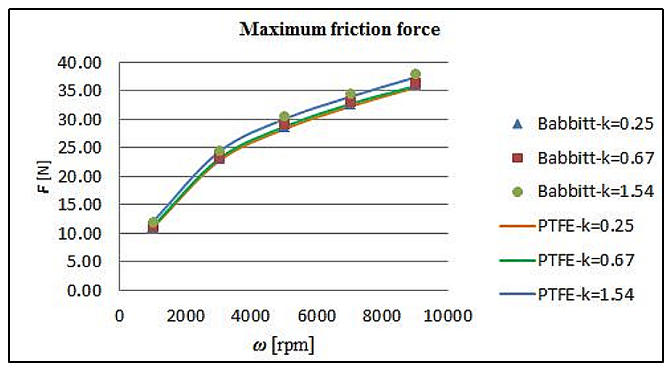
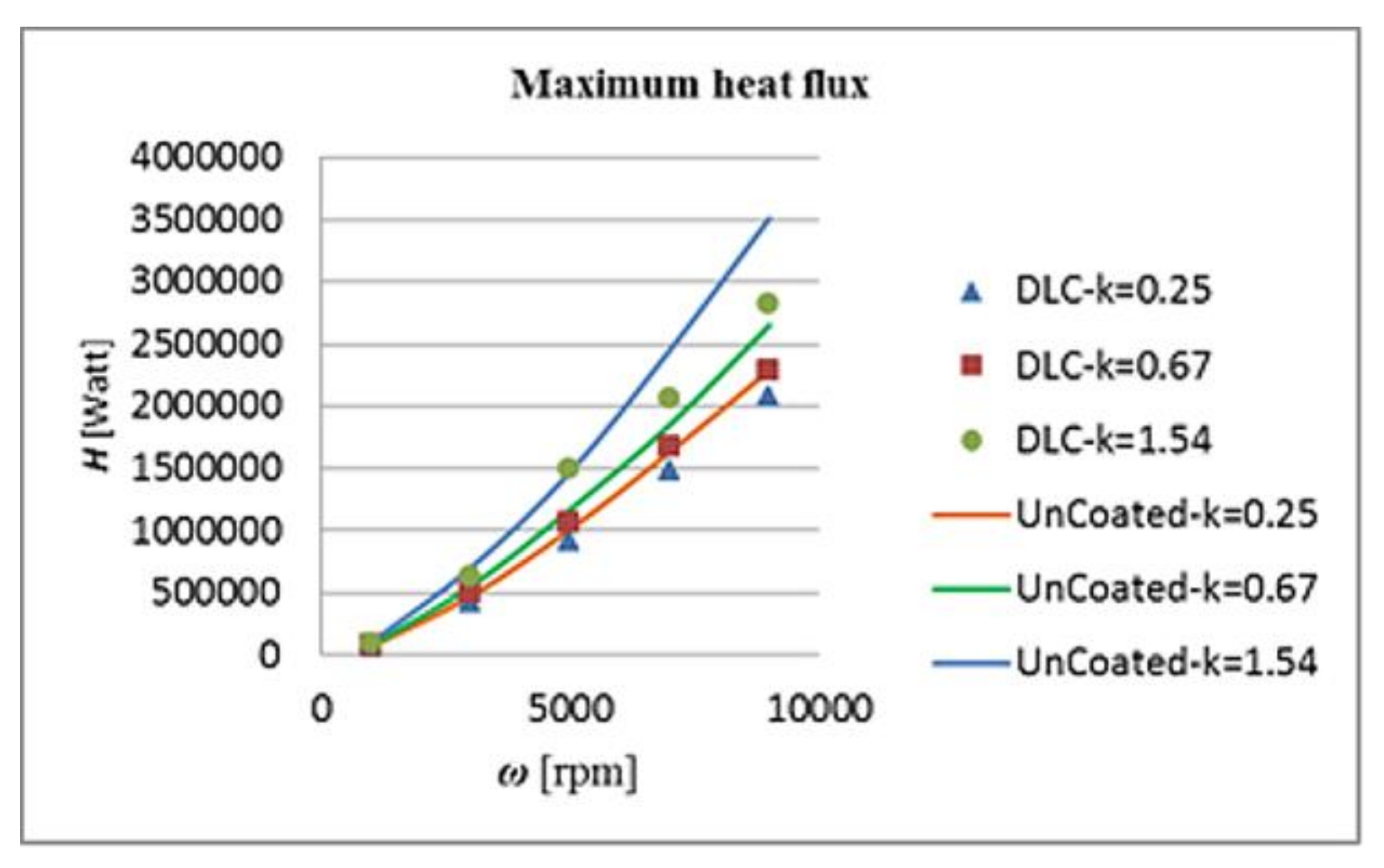
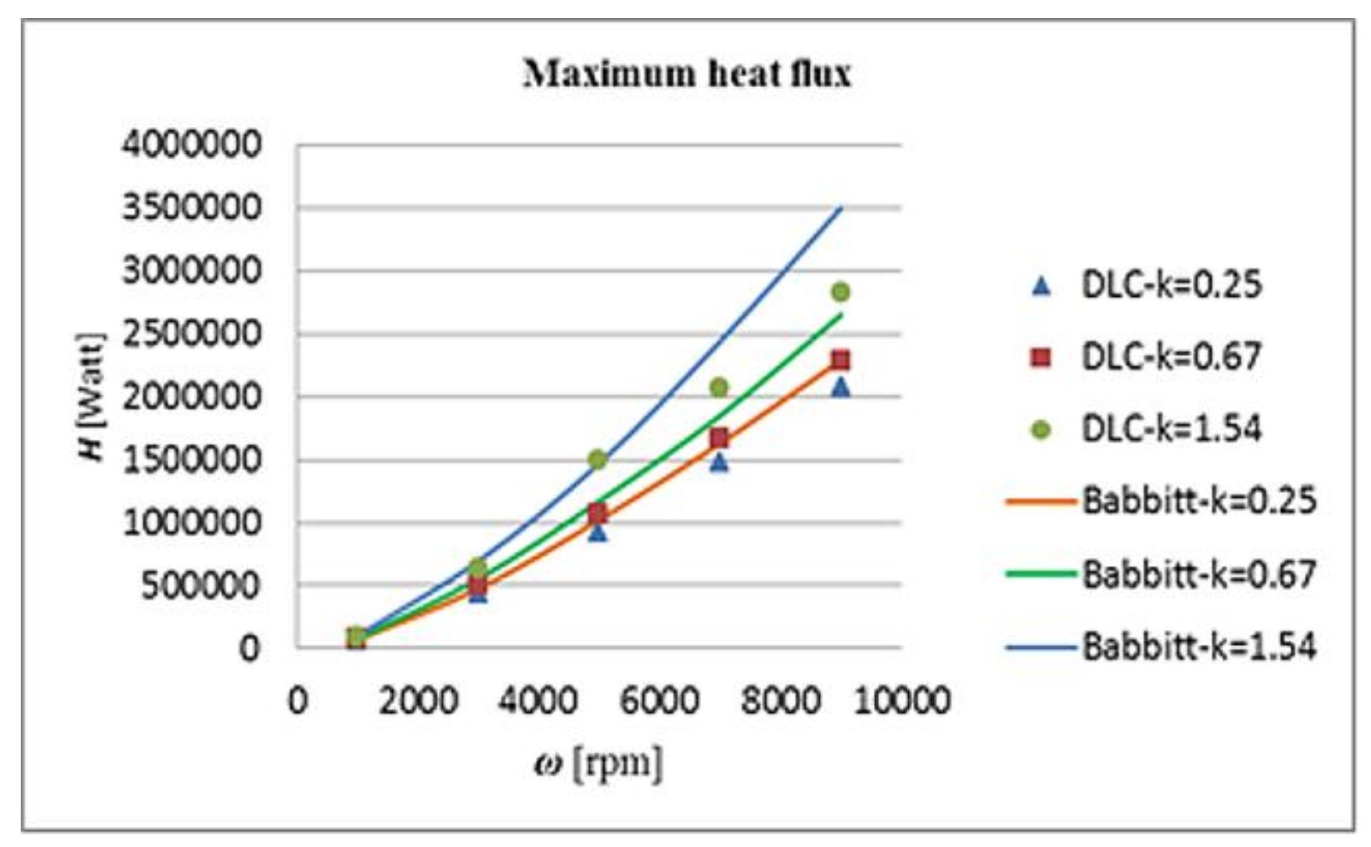
The Babbitt coating shows up to 5% higher pressure, 15% lower temperature but 2% higher friction force compered to PTFE. Similarly, when compared to DLC, the corresponding values are 2.5% higher pressure, 7% lower temperature but 1% higher friction force. The low thermal conductivities of DLC and PTFE result in higher temperatures and lower viscosity values for the lubricant. Lower viscosity values result in lower pressure, which corresponds to lower load capacity for the bearing.
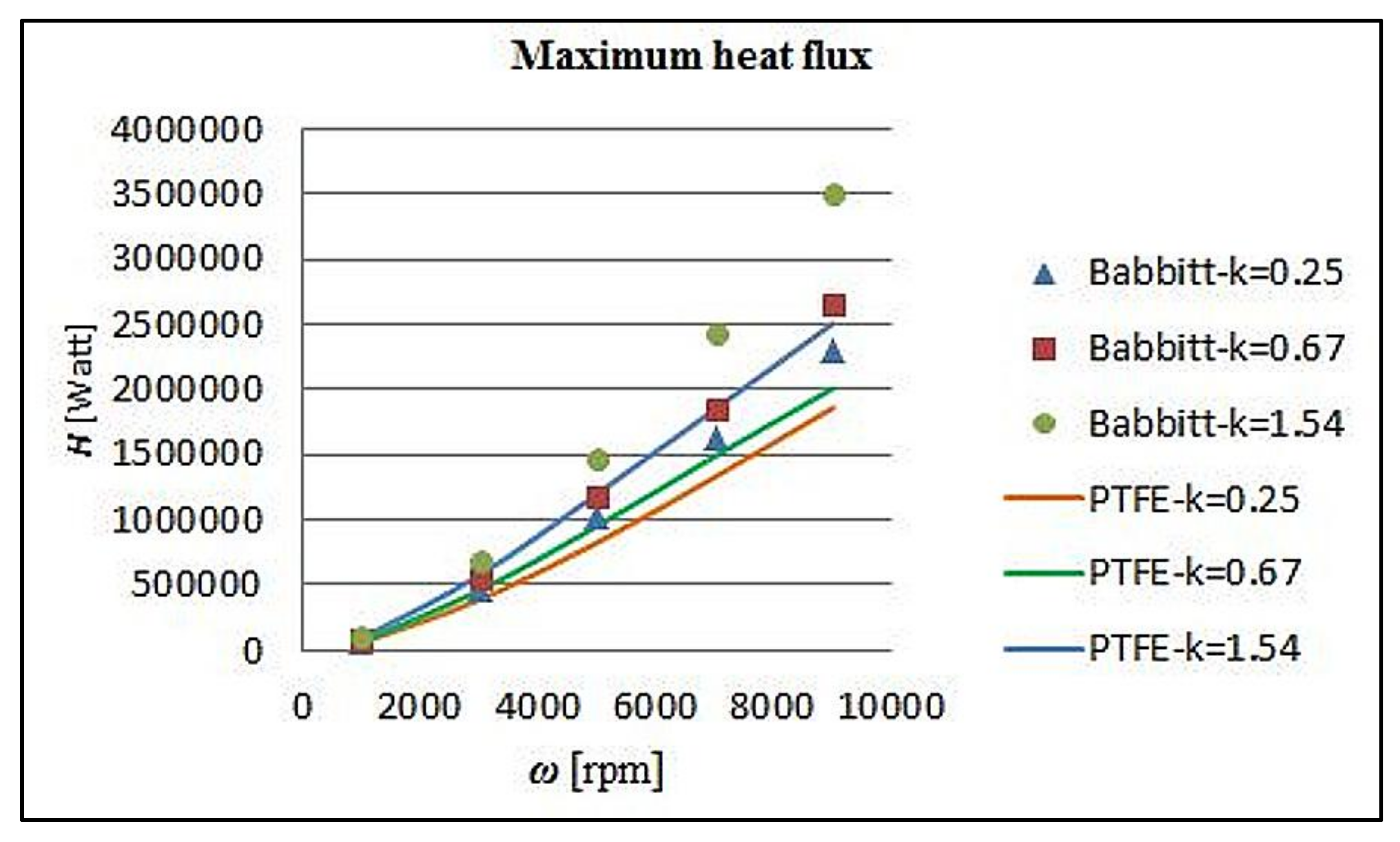
The mechanical and thermal properties of PTFE and DLC allow them to be appropriate for a wider range of applications in terms of minimum film thickness and lubricant temperatures. However, DLC shows up to 2.5% higher pressure and 7% lower temperature for the worst case studied, with 1.1% higher friction force for the DLC. PTFE has lower thermal conductivity than DLC. As a result, higher temperatures are observed in the lubricant during operation, which end up in lower viscosity values that affect the flow field and the pressure drops together with the load capacity of the bearing.
To summarize, the DLC coating seems to be less harmful for the flow and the thermal fields compared to PTFE due to its higher thermal conductivity. At the same time, the DLC coating gives the opportunity to tailor the bearing’s properties according to the application, just as the PTFE coating also does. As a result, the DLC coating is regarded as being more efficient than the PTFE one for thrust bearing applications. Finally, showing a very promising behavior, the DLC coating is generally suggested for further investigations in different bearing applications.

Author Contributions

K.K. performed the simulations, analyzed the results and wrote the main body of the paper. D.A.B. consulted concerning the design of the simulations and participated in the scientific discussions. P.G.N. revised the paper, performed the methodology and validation of the results paper. S.T. supported the interpretation and validation of the results and proof read the paper.

Conflicts of Interest

The authors declare no conflict of interest.

Nomenclature

A total area of bearing pads [m2]
B rotor’s width [m]
C 1 μ first viscosity coefficient—absolute temperature at which μ = μν (323 K)
C 2 μ second viscosity coefficient according to Sutherland’s law = 3800
C 3 μ third viscosity coefficient according to Sutherland’s law = 30,000
C p specific heat [J/Kg K]
h film thickness [m]
H 0 , H 1 outlet, inlet film thickness [m]
h c convective heat transfer coefficient [W/(m2 K)] or [W/(m2 °C)]
H min minimum film thickness [m]: H min = min ( H 0 , H 1 )
k convergence ratio: k = ( H 1 H 0 ) / H 0
K thermal conductivity [W/(m K)]
K r thermal conductivity of the rotor [W/(m K)]
K s thermal conductivity of the stationary pad [W/(m K)]
Npnumber of bearing’s pads
p absolute pressure [Pa]
Q v volumetric heat source (not taken into account)
ReReynolds Number
T absolute temperature [K]
T a ambient temperature [K]
T o i l lubricant temperature [K]
T r rotor temperature [K]
T s stationary pad temperature [K]
V linear rotor velocity [m/s]
V x linear rotor velocity-x direction [m/s]
V y linear rotor velocity-y direction [m/s]
V z linear rotor velocity-z direction [m/s]
μ viscosity coefficient [Pas]
μ ν nominal viscosity (0.036 Pas)
ρ density [Kg/m3]

References

  1. Dowson, D.; Hudson, J. Thermohydrodynamic analysis of the infinite slider bearing: Part I, the plane inclined slider bearing. Proc. Inst. Mech. Eng. 1963, 34, 34–44. [Google Scholar]
  2. Elrod, H. Efficient numerical method for computation of the thermohydrodynamics of laminar lubricating films. J. Tribol. 1991, 113, 506–511. [Google Scholar] [CrossRef]
  3. Chowdhury, S.; Ahmadi, G. Thermodynamic analysis of wide thrust bearings operating in laminar inertial flow regimes. Tribol. Int. 1986, 19, 281–288. [Google Scholar] [CrossRef]
  4. Neale, M.J. The Tribology Handbook; Butterworth-Heinemann: Oxford, UK, 1995. [Google Scholar]
  5. Shan, X.C.; Zhang, Q.D.; Sun, Y.F.; Maeda, R. Studies on a Micro Turbine Device with both Journal- and Thrust-Air Bearings. Microsyst. Technol. 2007, 13, 1501–1508. [Google Scholar] [CrossRef]
  6. Boncompain, R.; Fillon, M.; Frene, J. Analysis of thermal effects in hydrodynamic bearings. J. Tribol. 1986, 108, 219–224. [Google Scholar] [CrossRef]
  7. Ezzat, H.; Rohde, S. A study of the thermohydrodynamic performance of finite slider bearings. J. Tribol. 1973, 95, 298–307. [Google Scholar] [CrossRef]
  8. Almqvist, T.; Glavatskikh, S.; Larsson, R. THD analysis of tilting pad thrust bearings—Comparison between theory and experiments. J. Tribol. 2000, 122, 412–417. [Google Scholar] [CrossRef]
  9. Khonsari, M. A review of thermal effects in hydrodynamic bearings part I: Slider and thrust bearings. ASLE Trans. 1987, 30, 19–25. [Google Scholar] [CrossRef]
  10. Tanaka, M. Recent thermohydrodynamic analyses and designs of thick-film bearings. Proc. Inst. Mech. Eng. Part J J. Eng. Tribol. 2000, 214, 107–122. [Google Scholar] [CrossRef]
  11. Kalin, M.; Velkavrh, I.; Vižintin, J. The Stribeck curve and lubrication design for Non-fully wetted surfaces. Wear 2009, 267, 1232–1240. [Google Scholar] [CrossRef]
  12. Kalin, M.; Polajnar, M. The Effect of Wetting and Surface Energy on the Friction and Slip in Oil Lubricated Contacts. Tribol. Lett. 2013, 52, 185–194. [Google Scholar] [CrossRef]
  13. Kalin, M.; Polajnar, M. The wetting of steel, DLC coatings, ceramics and polymers with oils and water: The importance and correlations of surface energy, surface tension, contact angle and spreading. Appl. Surf. Sci. 2014, 293, 97–108. [Google Scholar] [CrossRef]
  14. Björling, M.; Isaksson, P.; Marklund, P.; Larsson, R. The influence of DLC coating on EHL friction coefficient. Tribol. Lett. 2012, 47, 285–294. [Google Scholar] [CrossRef]
  15. Glavatskih, S.B. Evaluating thermal performance of a PTFE-faced tilting pad thrust bearing. J. Tribol. 2003, 125, 319–324. [Google Scholar] [CrossRef]
  16. Mahieux, C. Experimental characterization of the influence of coating materials on the hydrodynamic behavior of thrust bearings: A comparison of Babbitt, PTFE, and PFA. J. Tribol. 2005, 127, 568–574. [Google Scholar] [CrossRef]
  17. Zhou, J.; Blair, B.; Argires, J.; Pitsch, D. Experimental Performance Study of a High Speed Oil Lubricated Polymer Thrust Bearing. Lubricants 2015, 3, 3–13. [Google Scholar] [CrossRef]
  18. Ricci, R.; Chatterton, S.; Pennacchi, P.; Vania, A. (Eds.) Multiphysics Modeling of a Tilting Pad Thrust Bearing: Comparison Between White Metal and Polymeric Layered Pads. In Proceedings of the ASME 2011 International Design Engineering Technical Conferences and Computers and Information in Engineering Conference, Washington, DC, USA, 28–31 August 2011; American Society of Mechanical Engineers: New York, NY, USA, 2011. [Google Scholar]
  19. Jahanmir, S.; Hunsberger, A.Z.; Heshmat, H. Load capacity and durability of H-DLC coated hydrodynamic thrust bearings. J. Tribol. 2011, 133, 031301. [Google Scholar] [CrossRef]
  20. Glavatskih, S.B.; Fillon, M. TEHD analysis of thrust bearings with PTFE—Faced pads. Trans. ASME J. Tribol. 2006, 128, 49–58. [Google Scholar] [CrossRef]
  21. Ettles, C.; Knox, R.; Ferguson, J.; Horner, D. Test results for PTFE-faced thrust pads, with direct comparison against Babbitt-faced pads and correlation with analysis. J. Tribol. 2003, 125, 814–823. [Google Scholar] [CrossRef]
  22. Pap, B.; Fillon, M.; Guillemont, M.; Bauduin, L.; Chocron, J.; Gédin, P.; Biadalla, L. Experimental and Numerical Analysis on the Seizure of a Carbon-Filled PTFE Central Groove Journal Bearing during Start-Up Period. Lubricants 2018, 6, 14. [Google Scholar] [CrossRef]
  23. Aurelian, F.; Patrick, M.; Mohamed, H. Wall slip effects in (elasto) hydrodynamic journal bearings. Tribol. Int. 2011, 44, 868–877. [Google Scholar] [CrossRef]
  24. Bielec, M.; Leopard, A. (Eds.) Tilting Pad Thrust Bearings: Factors Affecting Performance and Improvements with Directed Lubrication; The Institution of Mechanical Engineers, Tribology Convention: Westminster, UK, 1970. [Google Scholar]
  25. Periodic Table. Available online: http://www.periodictable.com (accessed on 28 October 2017).
  26. Engineering Toolbox. Available online: http://www.engineeringtoolbox.com (accessed on 23 December 2017).
  27. Shamsa, M.; Liu, W.L.; Balandin, A.A.; Casiraghi, C.; Milne, W.I.; Ferrari, A.C. Thermal conductivity of diamond-like carbon films. Appl. Phys. Lett. 2006, 89, 161921. [Google Scholar] [CrossRef]
  28. Zhou, Z.F.; Li, K.Y.; Bello, I.; Lee, C.S.; Lee, S.T. Study of tribological performance of ECR–CVD diamond-like carbon coatings on steel substrates Part 2. The analysis of wear mechanism. Wear 2005, 258, 1589–1599. [Google Scholar] [CrossRef]
  29. Blumm, J.; Lindemann, A.; Meyer, M.; Strasser, C. Characterization of PTFE Using Advanced Thermal Analysis Techniques. Int. J. Thermophys. 2010, 31, 1919–1927. [Google Scholar] [CrossRef]
Figure 1. (a) Thrust bearing assembly and (b) schematic of pivoted pad thrust bearing.
Lubricants 06 00050 g001
Figure 2. Viscosity model—viscosity variation with respect to temperature.
Lubricants 06 00050 g002
Figure 3. Three-dimensional model of the rotor, lubricant, coating layer and stationary pad.
Lubricants 06 00050 g003
Figure 4. Pad’s load: comparison between simulation and nominal load.
Lubricants 06 00050 g004
Figure 5. Pad’s temperature: comparison between simulation and nominal temperature.
Lubricants 06 00050 g005
Figure 6. Three-dimensional representation of the simulated pad and contour area.
Lubricants 06 00050 g006
Figure 7. Pressure distribution [Pa]. k = 0.67, rotor’s velocity 5000 rpm, uncoated bearing.
Lubricants 06 00050 g007
Figure 8. Temperature distribution [K]. k = 0.67, rotor’s velocity 5000 rpm, uncoated bearing.
Lubricants 06 00050 g008
Figure 9. Viscosity distribution [Pa s], 9000 rpm and k = 1.54. (a) uncoated pad; (b) babbitt coated pad; (c) DLC coated pad; (d) PTFE coated pad.
Lubricants 06 00050 g009
Figure 10. k = 0.67, rotor’s velocity 5000 rpm, DLC coated bearing. (a) Temperature [K] distribution on the rotor’s side; (b) temperature [K] distribution on the pad’s side.
Lubricants 06 00050 g010
Figure 11. Maximum lubricant pressure: DLC coated–uncoated pad.
Lubricants 06 00050 g011
Figure 12. Maximum lubricant pressure: DLC coated–Babbitt coated pad.
Lubricants 06 00050 g012
Figure 13. Maximum lubricant pressure: DLC coated–PTFE coated pad.
Lubricants 06 00050 g013
Figure 14. Maximum lubricant pressure: Babbitt coated–PTFE coated pad.
Lubricants 06 00050 g014
Figure 15. Maximum lubricant temperature: DLC coated–uncoated pad.
Lubricants 06 00050 g015
Figure 16. Maximum lubricant temperature: DLC coated–Babbitt coated pad.
Lubricants 06 00050 g016
Figure 17. Maximum lubricant temperature: DLC coated–PTFE coated pad.
Lubricants 06 00050 g017
Figure 18. Maximum lubricant temperature: Babbitt coated–PTFE coated pad.
Lubricants 06 00050 g018
Figure 19. Maximum friction force on the sector pad’s surface: DLC coated–uncoated pad.
Lubricants 06 00050 g019
Figure 20. Maximum friction force on the sector pad’s surface: DLC coated–Babbitt coated pad.
Lubricants 06 00050 g020
Figure 21. Maximum friction force on the sector pad’s surface: DLC coated–PTFE coated pad.
Lubricants 06 00050 g021
Figure 22. Maximum friction force on the sector pad’s surface: Babbitt coated–PTFE pad.
Lubricants 06 00050 g022
Figure 23. Maximum heat flux: DLC coated–uncoated pad.
Lubricants 06 00050 g023
Figure 24. Maximum heat flux: DLC coated–Babbitt coated pad.
Lubricants 06 00050 g024
Figure 25. Maximum heat flux: DLC coated–PTFE coated pad.
Lubricants 06 00050 g025
Figure 26. Maximum heat flux: Babbitt coated–PTFE coated pad.
Lubricants 06 00050 g026
Table 1. Validation data.
Velocity (rpm)Minimum Film Thickness (μm)Simulation Pad Load (N)Experimental Pad Load (N) [24]Simulation Max Pad Temp (°C)Experimental Pad Temp (°C) [24]
280010.03005.82943.572.0779
400010.62985.02943.580.2887
500011.02916.52943.585.3494
600011.23047.62943.589.92100
700011.42910.42943.593.99105
Table 2. Material properties. DLC: diamond like carbon.
MaterialDensity (kg/m3)Specific Heat (J/kg K)Thermal Conductivity (W/mK)
Bronze Rotor8200435110
Steel Pad775045243
Babbitt740029740
DLC18609700.6
PTFE220012000.3

