The Running-in of Lubricated Metal-Metal Contacts—A Review on Ultra-Low Wear Systems

Fraunhofer IWM MikroTribologie Centrum, Rintheimer Querallee 2a, 76131 Karlsruhe , Germany
Lubricants 2018, 6(2), 54; https://doi.org/10.3390/lubricants6020054
Submission received: 11 April 2018
/
Revised: 11 May 2018
/
Accepted: 15 May 2018
/
Published: 8 June 2018
(This article belongs to the Special Issue Applied Nanotribology)
Abstract
:The running-in of lubricated metal–metal contacts leading to ultra-low wear is inseparably connected with the formation of the third body and vice versa. Adequate tribological stressing provides the system with a power density that leads to complex changes of topography, near-surface morphology and chemical composition. During the running-in these changes proceed until the system shows small friction and ultra-low wear rates and performs stable with low sensitivity to external perturbations. By means of high-resolution wear measurement as well as physical and chemical analysis the capability of a tribological system to develop the third body can be determined. Moreover, the running-in can be controlled by sample finishing, oil additivation and the sequence of initial stressing steps. This contribution summarizes 20 years of own research on ultra-low wear systems and its applications.
1. Introduction
Wear in modern lubricated mechanical systems—gear boxes, compressors, pumps or combustion engines—is characterized by ultra-low wear rates in the range of nanometers per hour. Due to intense loading at high sliding velocities, the stressing level at the asperities is frequently higher than the yield stress of the material. As a result, the asperities start to flow leading to an exchange of material of both friction bodies among one another and with the lubricant. This process is called mechanical intermixing [1]. Since the tribological contact of two asperities lasts only a few microseconds, the material becomes quenched at high cooling rate. As consequence of high cooling and shear, the materials gradually become nanocrystalline with a high concentration of foreign elements in the vicinity of the surface. In addition, the surface develops dissipative structures, which are very often in form of regular waves [2]. As result of plastic flow and intermixing at adequate energy level, a modified zone, the third body, with a thickness of several 10 to 100 nanometers evolves. The thickness of the third body is a function of the amount of energy dissipated at the microcontacts [3]. The third body, as described here, is not a layer on top such as a transfer film, but constitutes newly-formed material in the near-surface of both friction bodies. It is the result of mechano-chemical reactions.
To find the adequate energy level, the control of the running-in is of major importance. In addition, during this time the tribological long-term performance becomes determined. For ultra-low wear systems, running-in and third body formation are inseparable processes. The running-in provides the adequate energy level for the generation of the third body and the formed third body feeds back to the further course of the running-in. It has to be emphasized that nearly all tribological systems develop a third body and that this phenomenom is labeled with numerous different names. Depending on the level of stressing, the third bodies have different compositions, structures and properties. In this contribution the term “third body” refers to the state that enables the tribological system to develop ultra-low wear rates. The state of ultra-low wear rates is accompanied by low friction, high system stability and low sensitivity. The terms stability and sensitivity will be described in Section 2.3.
2. Friction and Wear Behavior
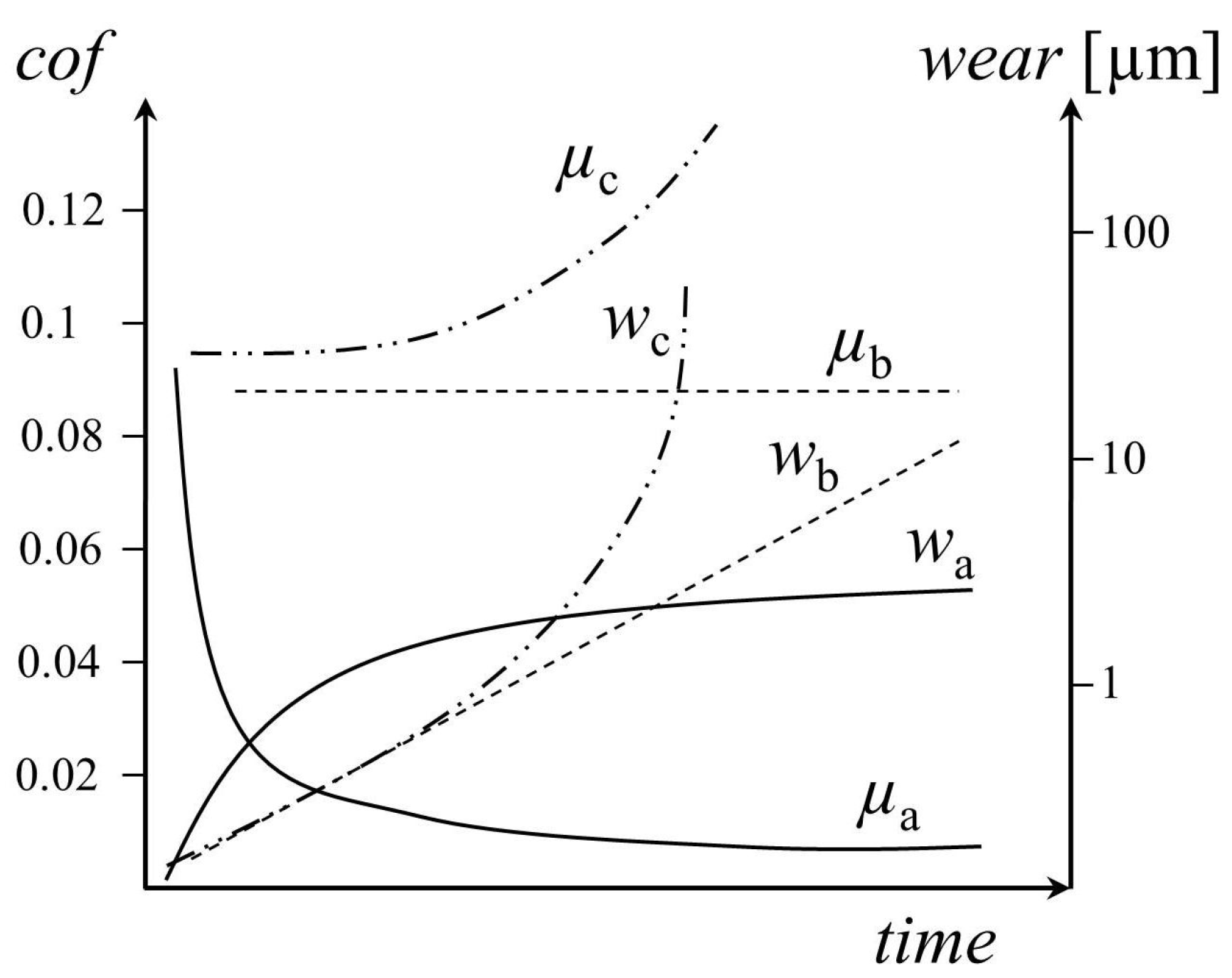
2.1. General Friction and Wear Trends
Friction and wear can pursue three different paths during the first minutes or hours of operation, see Figure 1. The running-in, as addressed by this paper, is denoted by for wear and for friction. and characterize a behavior that is characterized by a linear increase of wear and constant friction. This type of system does not develop the third body in the meaning of this paper, since friction power density is too high. Usually these kinds of systems with a deep (i.e., micrometer) mechanical interaction are described in tribology textbooks and the majority of scientific publications. Finally, and stand for a systems that quickly runs into catastrophic failure. Soon after start, friction and wear show exponential increase. Both last systems have in common, that the involved materials lose their capability to develop the special type of third body as needed for the development of ultra-low wear rates.
2.2. The Energetic View on Friction and Wear
Running-in and third body formation are energetically controlled processes. To describe the level of tribological interaction, the power density expressed as:
is used. is the friction force and v is the sliding velocity. Friction force is influenced by the joint response of both solids, the lubricant and the environment. A denotes the macroscopic contact area. As a first approach, the geometric contact area can be inserted. For more advanced studies, however, a measured initial contact area should be used or contact mechanics simulation should be considered to compute the real contact area and its evolution.
With respect to friction, Bowden and Tabors approach [4]:
can be applied, where is the material-dependent shear coefficient representing the combined response of both (flowed) solids and the lubricant. Equation (2) represents the sum of all single asperity contacts. When a system is adequately stressed, friction decreases throughout the experiment due to decreasing . This in turn means that both materials can be sheared more easily, i.e., by consuming less energy.
The main paths of energy dissipation are heat and wear generation as well as a significant change of near-surface material within the range of a few hundred nanometers [5].
The largest portion of energy dissipated in the system results in heat and change of material . Due to mechanical intermixing and plastic flow at the asperity level, the involved materials change with respect to chemical composition, morphology and mechanical properties. The power spent on wear imposes the smallest contribution to this equation. All terms are time-dependent.
2.3. Sensitivity and Stability
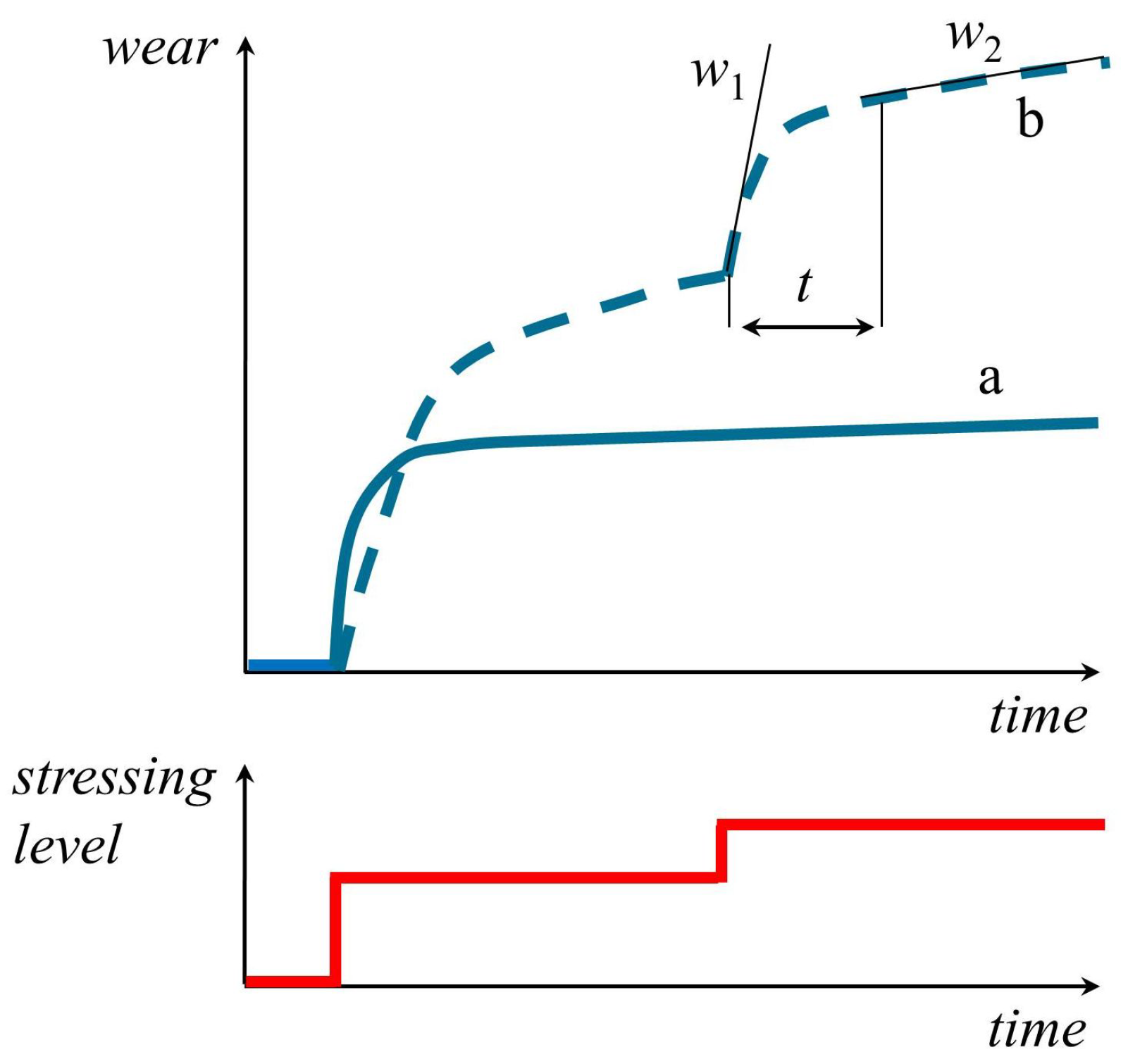
In addition to friction and wear, sensitivity and stability are important parameters to describe the performance of a tribological system [6]. Sensitivity reflects the property of the system to develop negligible response of friction and wear to changes of the stressing conditions such as oil temperature, load or speed, see Figure 2.
The analysis of sensitivity allows the evaluation of various influencing factors without any risk of severe damage to the analyzed machine parts, as for example, the load limits of bearings in the case of a power enhancement or decrease of oil viscosity. Especially for the development of lubricants, temperature sensitivity is of particular importance. In many cases additives become effective only above a certain minimum temperature. However, if a certain maximum temperature is exceeded, the additives may deteriorate. Special attention should be paid also to fluctuations of the operational conditions, since some machine parts might become impaired beyond any remedy after exceeding the admissible working load for only very short periods of time. As a consequence of these fluctuations, high wear rates might result even at low-load levels.
Stability refers to the property of the system to quickly pass the running-in and to adopt a constant wear rate. With respect to that definition both curves in Figure 2 show stable behavior, since constant wear rates were achieved. System (a) behaves more stable, since its constant wear rate was achieved quicker than by system (b). In summary, friction, wear, sensitivity and stability are necessary entities to comprehensively describe a tribological system.
2.4. Evaluation of Running-in Wear
As shown in Figure 2, three characteristic values are monitored and used to evaluate the running-in behavior [7]:
- the wear rate immediately after a variation of the operating conditions towards higher loads ,
- the period of time t until a constant value of wear rate is reached,
- the wear rate upon reaching a stationary wear behavior .
During the running-in process it often emerges (by extrapolation of the wear behavior) that machine parts will not stand the required loads. In such cases the tests have to be stopped.
3. Running-in Performance
3.1. Running-in Corridor
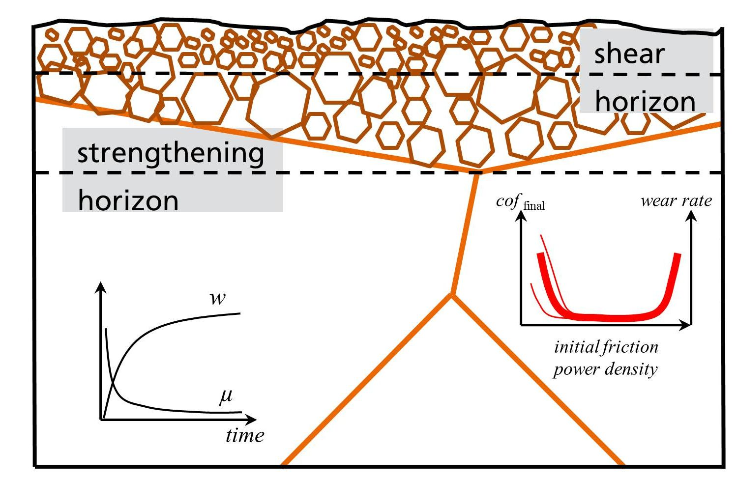
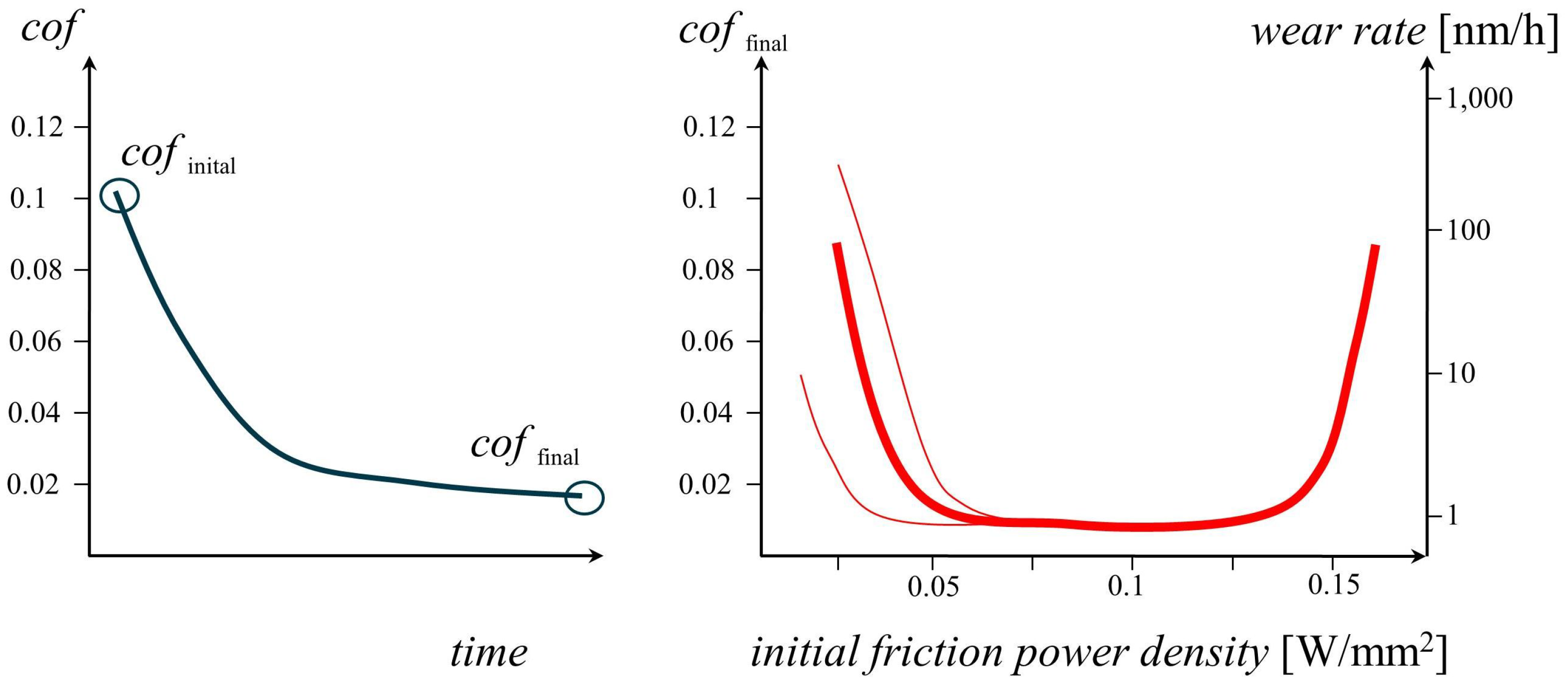
It was shown by numerous experiments [8,9,10,11,12] that friction and wear behave extremely repeatable provided that the adequate energetic range for the running-in was found. It can be demonstrated that the coefficient of friction at the end of the running-in cof, crucially depends on the magnitude of the initial coefficient of friction cof, since the initial friction power density determines how the third body forms. The results obtained for friction coefficient and wear rate show that a running-in corridor exists, see Figure 3. It turned out that the corridor has a certain width in accordance to the tribological experience with the materials in application. For example, systems with gray cast iron as one of the friction bodies are known to respond with great stability and low sensitivity. Accordingly, these systems adjust to a wide range of boundary conditions. Other systems like AlSi versus steel are more difficult to operate. The running-in corridor is much narrower and shifted to lower initial friction power densities.
The results for friction and wear can be approximated by a single master curve. The width of the corridor is a function of the tribological stressing conditions, i.e., load, sliding velocity, temperature, a.s.o. In addition, the type of materials, their finishing and the lubricant impose great impact. All corridors show a larger data scatter at the left border. Whereas at the right hand side of the corridor the system is driven into catastrophic failure, at the left hand side the systems partly jump between high and low friction. In this range the system is highly sensitive to external changes—load, temperature, viscosity—and internal deviations such as changes in topography or structural changes due to finishing. These changes act on the friction power density and determine whether the system is able to start mechano-chmeical reactions and to develop the third body. At the right hand side friction power density is too high preventing third body formation because of excessively high wear rates. To obtain the friction power density the geometric area of contact was used. The model can be refined when instead of the geometric contact area the real area of contact is used. However this approach requires sophisticated contact mechanics.
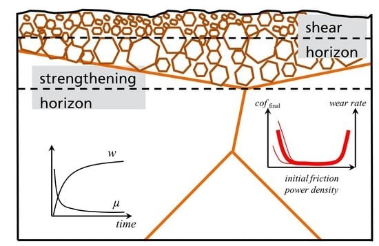
3.2. Structural and Chemical Evolution
To explain the antiwear properties of nano-crystalline layers, literature describes a variety of mechanisms [13]. Due to shear the grain size decreases gradually towards a nano-crystalline structure [14]. As it is known from the Hall-Petch effect, the mechanical strength increases with decreasing grain size due to grain boundary strengthening and dislocation pile up [15].
Since the mobility of dislocations is limited by the grain size, motion of dislocations is gradually suppressed when the grains become smaller. The nano-crystalline layers become extremely hard and therefore protect the surface from pressure peaks. The deformation runs predominantly elastically. The boundary between nano-crystalline material and bulk is called strengthening horizon [16], see Figure 4.
The other mechanism considers the effect, that close the surface grains with a size of less than 10 nm can be found, suggesting that the so-called inverse Hall-Petch effect kicks in [8]. When grains reach a critical size and the volume of grain boundaries represents a significant part of the entire material volume, the diffusion-driven (fluid-like) deformation mechanism becomes active [17,18,19,20]. As a consequence, nano-crystalline layers become superplastic and soft. Superplastic means, that once they are sheared, they exhibit low shear strength [21] and probably non-Newtonian fluid-like characteristics. These layers develop every time two asperities collide, forming the third body [22,23] which acts as a solid lubricant. The range of material where shear is accommodated, is therefore called shear horizon [16].
The combination of softening and hardening describe the tribological observations very well, when applied to the appropriate depth level. Whereas the material above shear horizon develops by plastic flow and intermixing, new material at the interface of strengthening horizon and bulk emerges by cyclic creep due to repeated stressing events, i.e., frequent asperity collisions [24].
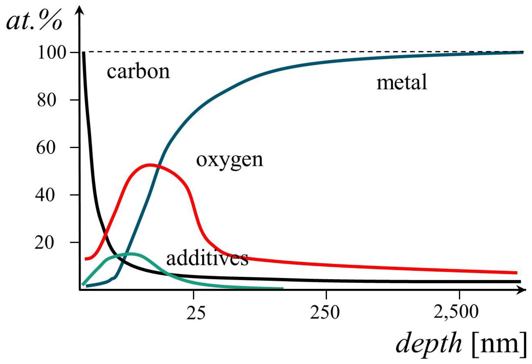
With respect to chemical composition, the near-surface region, i.e., the material between surface and shear horizon, shows incorporations of foreign elements from the oil (C and CH), anti-wear additives (S, P, Zn) and elements from the counter body. In addition, oxygen can be detected, however, with larger penetration depth, see Figure 5. The deeper intake of oxygen cannot be explained solely by plastic flow and intermixing. Quinn and Sulivan reported on an FeO layer [25] built up at elevated temperatures. The production of heat—as described by the flash temperature concept [26,27]—causes a diffusion process that proceeds in parallel to mechanical intermixing, mainly observed for oxygen.
4. Running-in Optimization
4.1. Parameter Fields
Different sequences of loads and sliding velocities result in different running-in behaviors [28]. To consider all operational conditions a tribological system will be subjected to during its lifetime, purposeful initial stressing by passing through an appropriate parameter field is necessary.
When the tribological behavior of the system under investigation is unknown, it is advisable to subject the system to a thorough analysis of friction and wear, with respect to sliding velocity and normal force (Stribeck analysis). The parameter range of velocity and normal force thereby depends on the field of application of this tribo-system. The stressing points that yield the most intensive response of friction and wear are called key operation points. A sequence of these key operation points can be used to construct a parameter field for running-in [7]. However, as of today, no straightforward procedure for the generation of a successful running-in procedure exists.
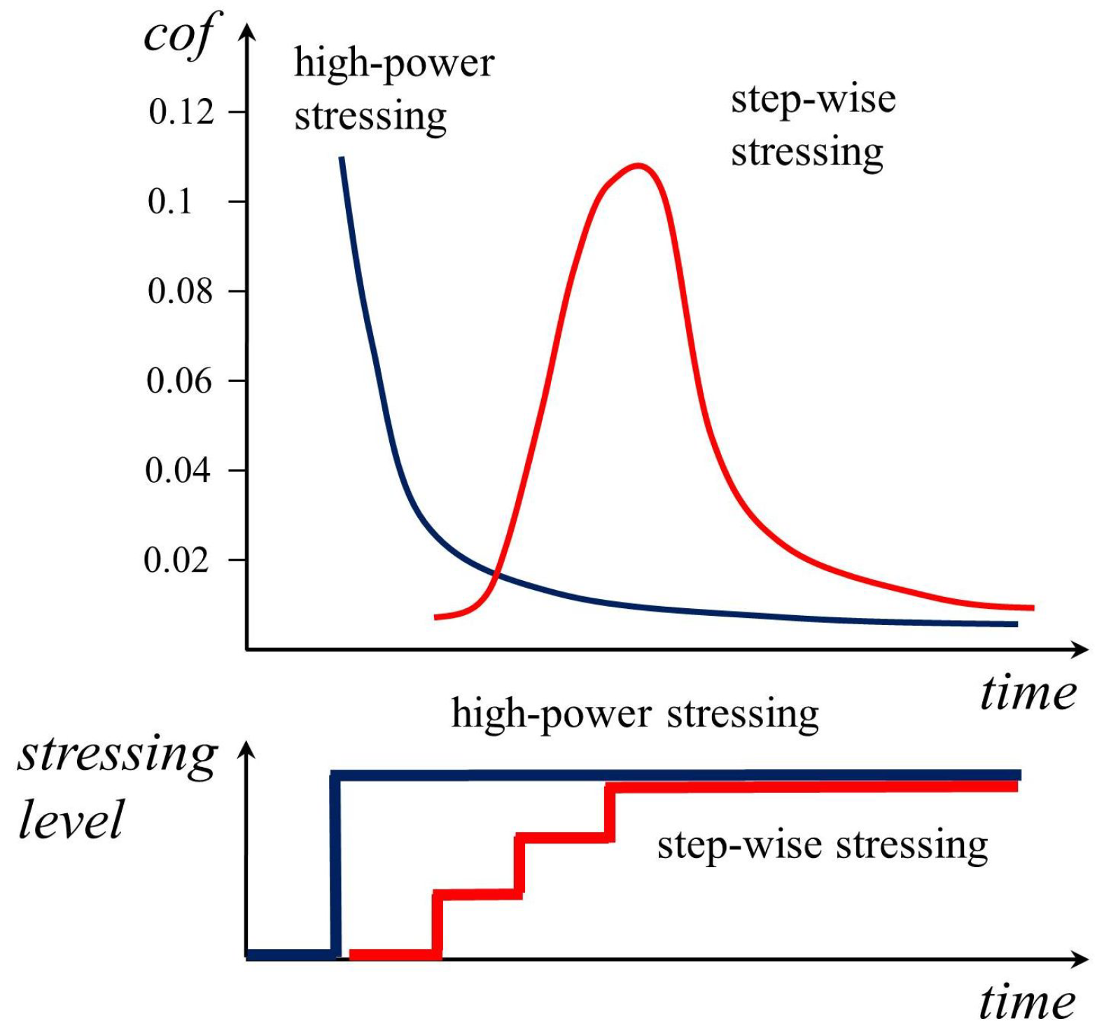
In addition to the selection of stressing points, a running-in depends on the conditioning of involved materials, see below. Tribological pairings which already have a history, i.e., a longer time in practical use, can usually be stressed at higher level than newly-introduced pairings. The reason for this kind of behavior is that the pairing with tribological history has experienced an evolutionary optimization of the finishing routines. Pairings without optimized finishings have to be sent through a step-wise stressing with increasing loads, see Figure 6.
When during the first operation point or sequence of operation points a running-in was achieved, turns low and the dissipated power for each following operation point keeps low values. The running-in performance of a tribological system is rendered excellent, when the wear surfaces are conditioned sufficiently, by the formation of the third body.
4.2. Pre-Conditioning
In addition to the initial friction power density determined by sliding velocity, normal force, type of lubrication and additivation, the achievement of the adequate energy level for running-in crucially depends on the machine piece finishing [29]. Therefore, mechanical conditioning of the tribological system—e.g., polishing or lapping—plays an important role. When by conditioning the near-surface material is furnished with the adequate microhardness (due to grain size reduction), a high-power running-in is possible, quickly inducing low friction and wear. When conditioning is not possible, the high-power running-in has to be replaced by a step-wise increase in normal force, see Figure 6. In this case the first stressing steps serve as sample finishing, enabling the tribological system to perform the running-in.
In terms of finishing procedure the one with a high portion of rubbing instead of cutting is most valuable for tribological conditioning. Consequently, honing performs better than grinding, lapping imposes a significantly greater influence when compared to polishing and turning with optimized cutting tools yields a better tribological result than with standard tools without optimized geometry.
Macrohardness comes into play when plastic deformation possesses subordinate influence. When both friction bodies have a similar macrohardness and due to conditioning similar microhardness, the high power running-in can be applied. When no conditioning was performed and the friction bodies show a large difference in macrohardness, even the step-wise increase in load does not lead to the running-in. For this case the combination of materials has to be changed [8].
5. Testing
5.1. Continuous Wear Measurement
The only method to address systems with ultra-low wear rates is radionuclide technique (RNT). RNT is based on counting gamma pulses emitted by wear debris leaving the tribological interface.
When using radionuclide technique, first and/or second body can be marked radioactively. The activity is extremely low, requiring the sensor setup to be shielded with lead. Due to wear, radioactive particles can be found in the oil circuit. The activity in the oil is measured and correlated to the mass of the wear particles after calibration. The greatest advantage of the method is its ability to measure wear continuously. To obtain wear tracers, either cyclotron or a low-energy neutron source can be used. Upon tribological stressing nanometer-sized wear particles are generated [30]. The oil circuit of the tribometer has to be connected to a gamma detector allowing continuous monitoring of wear in the oil. To account for decay effects, a reference measuring device is included in the oil circulation. With the RNT, micrograms of wear can be detected in the oil circuit which corresponds to a wear rate of a few nanometers per hour. Further details of RNT can be found in [7,31].
5.2. Analytics
The extremely low wear rates implicate that physical and chemical analysis before and after the tribological test has to probe the near-surface material of both friction bodies. Appropriate methods are atomic force or white light microscopy for topography analysis, photoelectron or Auger electron spectroscopy for chemical analysis and focused ion beam analysis for microstructural observation.
In addition, to characterize the mechanical properties of the near-surface material, nanoindentation can be used. As a first order approximation, nanoindentation hardness can be considered a measure of conditioning, since by changing grain-size and dislocation density, the microhardness is affected.
6. Conclusions
The following conclusions on systems developing ultra-low wear rates can be drawn:
- The running-in is the phase in the lifetime of a tribological system when the most important parameters such as friction coefficient, wear rate, stability and sensitivity become determined.
- Only adequate stressing conditions initiate this type of running-in. In most of the cases running-in can be achieved, when the initial stressing conditions are located inside an appropriate energetic corridor.
- The running-in generates a third body characterized by dissipative surface structures, nano-crystalline grain structure, the incorporation of foreign elements by plastic flow and mechanical intermixing. The third body is responsible for ultra-low wear and low friction.
- Running-in can be enforced by optimized parameter fields and by adequate sample finishing.
- The course of the running-in can be monitored by radionuclide technique and the properties of the third body can be evaluated by surface science methods.
Conflicts of Interest
The author declare no conflict of interest.
References
- Rigney, D.A. Transfer, mixing and associated chemical and mechanical processes during the sliding of ductile materials. Wear 2000, 245, 1–9. [Google Scholar] [CrossRef]
- Scherge, M.; Shakhvorostov, D.; Poehlmann, K. Fundamental wear mechanism of metals. Wear 2003, 255, 395–400. [Google Scholar] [CrossRef]
- Dienwiebel, M.; Scherge, M. Fundamentals of Friction and Wear on the Nanoscale; Springer: Berlin, Germany, 2014. [Google Scholar]
- Bowden, F. A review of the friction of solids. Wear 1958, 1, 333–346. [Google Scholar] [CrossRef]
- Shakhvorostov, D.; Poehlmann, K.; Scherge, M. An energetic approach to friction, wear and temperature. Wear 2004, 257, 124–130. [Google Scholar] [CrossRef]
- Linsler, D.; Schroeckert, F.; Scherge, M. Influence of subsurface plastic deformation on the running-in behavior of a hypoeutectic AlSi alloy. Tribol. Int. 2016, 100, 224–230. [Google Scholar] [CrossRef]
- Scherge, M.; Poehlmann, K.; Gerve, A. Wear measurement using radionuclide-technique (RNT). Wear 2003, 254, 801–817. [Google Scholar] [CrossRef]
- Brink, A.; Lichtenberg, K.; Scherge, M. Influencing the tibological performance by different initial microstructures and adjusting stressing levels during the running-in. Wear 2016, 360-361, 114–120. [Google Scholar] [CrossRef]
- Linsler, D.; Schlarb, T.; Weingaertner, T.; Scherge, M. Influence of subsurface microstructure on the running-in of an AlSi alloy. Wear 2015, 332–333, 926–931. [Google Scholar] [CrossRef]
- Scherge, M.; Linsler, D.; Schlarb, T. The running-in corridor of lubricated metal–metal contacts. Wear 2015, 342–343, 60–64. [Google Scholar] [CrossRef]
- Antusch, S.; Dienwiebel, M.; Nold, E.; Albers, P.; Spicher, U.; Scherge, M. On the tribochemical action of engine soot. Wear 2010, 269, 1–12. [Google Scholar] [CrossRef]
- Scherge, M.; Boettcher, R.; Kuerten, D.; Linsler, D. Multi-Phase Friction and Wear Reduction by Copper Nanopartices. Lubricants 2016, 4, 36. [Google Scholar] [CrossRef]
- Popov, V.; Kroener, E. Theory of elastoplastic media with mesostructure. Theor. Appl. Fract. Mech. 2001, 37, 299–310. [Google Scholar] [CrossRef]
- Shakhvorostov, D.; Gleising, B.; Buescher, R.; Dudzinski, W.; Fischer, A.; Scherge, M. Microstructure of tribologically induced nanolayers produced at ultra-low wear rates. Wear 2007, 263, 1259–1265. [Google Scholar] [CrossRef]
- Linz, M.; Ripoll, M.R.; Gachot, C.; Pauly, C.; Franek, F.; Muecklich, F. On the competition between plastic deformation and material detachment in ferritic/pearlitic steel under boundary lubrication. Wear 2017, 376–377, 813–821. [Google Scholar] [CrossRef]
- Scherge, M.; Brink, A.; Linsler, D. Tribofilms Forming in Oil-Lubricated Contacts. Lubricants 2016, 4, 27. [Google Scholar] [CrossRef]
- Schiøz, J.; Di Tolla, d.F.; Jacobsen, K.W. Softening of nanocrystalline metals at very small grain size. Nature 1998, 391, 561. [Google Scholar] [CrossRef]
- Arzt, E. Size effects in materials due to microstructural and dimensional constraints: A comparative review. Acta Mater. 1998, 46, 5611–5626. [Google Scholar] [CrossRef]
- Gleiter, H. Materials with ultrafine microstructures: Retrospectives and perspectives. Nanostruct. Mater. 1992, 1, 1–19. [Google Scholar] [CrossRef]
- Chokshi, A.; Rosen, A.; Karch, J.; Gleiter, H. On the validity of the hall-petch relationship in nanocrystalline materials. Scr. Metall. 1989, 23, 1679–1683. [Google Scholar] [CrossRef]
- Shakhvorostov, D.; Poehlmann, K.; Scherge, M. Structure and mechanical properties of tribologically induced nanolayers. Wear 2006, 260, 433–437. [Google Scholar] [CrossRef]
- Kragelsky, I.V.; Dobychin, M.N.; Kombalov, V.S. Chapter 6—Friction on Impact. In Friction and Wear; Kragelsky, I.V., Dobychin, M.N., Kombalov, V.S., Eds.; Elsevier: Pergamon, Turkey, 1982; pp. 208–218. [Google Scholar]
- Godet, M. The third-body approach: A mechanical view of wear. Wear 1984, 100, 437–452. [Google Scholar] [CrossRef]
- Fischer, A.; Weiss, S.; Wimmer, M.A. The tribological difference between biomedical steels and CoCrMo-alloys. J. Mech. Behav. Biomed. Mater. 2012, 9, 50–62. [Google Scholar] [CrossRef] [PubMed] [Green Version]
- Quinn, T.; Rowson, D.; Sullivan, J. Application of the oxidational theory of mild wear to the sliding wear of low alloy steel. Wear 1980, 65, 1–20. [Google Scholar] [CrossRef]
- Blok, H. The flash temperature concept. Wear 1963, 6, 483–494. [Google Scholar] [CrossRef]
- Kuhlmann-Wilsdorf, D. Flash temperatures due to friction and Joule heat at asperity contacts. Wear 1985, 105, 187–198. [Google Scholar] [CrossRef]
- Volz, J. Erstellung Optimierter Einlaufprogramme von Dieselmotoren; Karlsruhe Institute of Technology: Karlsruhe, Germany, 1977. [Google Scholar]
- Berlet, P.; Dienwiebel, M.; Scherge, M. The effect of sample finishing on the tribology of metal/metal lubricated contacts. Wear 2010, 268, 1518–1523. [Google Scholar] [CrossRef]
- Scherge, M.; Martin, J.; Poehlmann, K. Characterization of wear debris of systems operated under low wear-rate conditions. Wear 2006, 260, 458–461. [Google Scholar] [CrossRef]
- Ditroi, F.; Takacs, S.; Tarkanyi, F.; Reichel, M.; Scherge, M.; Gerve, A. Thin layer activation of large areas for wear study. Wear 2006, 261, 1397–1400. [Google Scholar] [CrossRef]
Figure 1.
General Friction and Wear Trends. cof = coefficient of friction.

Figure 2.
The running-in of stable but differently sensitive systems.

Figure 3.
(Left) Coefficient of friction during running-in and definitions of cof and cof; (Right) The running-in corridor.
Figure 3.
(Left) Coefficient of friction during running-in and definitions of cof and cof; (Right) The running-in corridor.

Figure 4.
Third body with shear and strengthening horizon.

Figure 5.
Depth profile of a tribological system after running-in.

Figure 6.
Different stressing scenario to achieve a running-in.

© 2018 by the author. Licensee MDPI, Basel, Switzerland. This article is an open access article distributed under the terms and conditions of the Creative Commons Attribution (CC BY) license (http://creativecommons.org/licenses/by/4.0/).
Share and Cite
MDPI and ACS Style
Scherge, M. The Running-in of Lubricated Metal-Metal Contacts—A Review on Ultra-Low Wear Systems. Lubricants 2018, 6, 54. https://doi.org/10.3390/lubricants6020054
AMA Style
Scherge M. The Running-in of Lubricated Metal-Metal Contacts—A Review on Ultra-Low Wear Systems. Lubricants. 2018; 6(2):54. https://doi.org/10.3390/lubricants6020054
Chicago/Turabian StyleScherge, Matthias. 2018. "The Running-in of Lubricated Metal-Metal Contacts—A Review on Ultra-Low Wear Systems" Lubricants 6, no. 2: 54. https://doi.org/10.3390/lubricants6020054
Note that from the first issue of 2016, this journal uses article numbers instead of page numbers. See further details here.