Article

Effects of Travel Speed on the Microstructure and Abrasion Resistance of Hardfacing Alloys Deposited with Composite Powder Particles and Solid Wire

School of Mechanical Engineering, Xiangtan University, Xiangtan 411105, China
*
Author to whom correspondence should be addressed.
Metals 2020, 10(6), 740; https://doi.org/10.3390/met10060740
Submission received: 25 April 2020 / Revised: 26 May 2020 / Accepted: 27 May 2020 / Published: 2 June 2020
(This article belongs to the Special Issue Hardfacing of Metals and Alloys)

Abstract

:
Composite powder particles (CPP) preset on base metals were fused with a solid wire to form a melt by the intense heat provided by the arc. An X-ray diffractometer, scanning electron microscopy, and energy dispersive spectrometer were employed to investigate the effects of travel speed on the microstructure and abrasion resistance. It was found that the microstructure of hardfacing alloys with CPP consists of γ-Fe, M7C3, and (Ti, V) C. With an increase in the travel speed from 3.5 to 6 mm/s, the microstructure with CPP changed from a hypoeutectic to hypereutectic structure. For hardfacing alloys with CPP, the increase in the travel speed not only contributed to a reduction of the dilution ratio of base metals, but also deliberately increased the volume fraction of primary M7C3-type carbides, which indicated that the bonding function executed on powder components led to a significant improvement in abrasion resistance and increased the utilization ratio of the alloying elements. The wear mechanism of hardfacing alloys included micro-cutting of abrasive particles and micro-spalling.

1. Introduction

Hardfacing is widely used in advanced machinery to improve the surface properties such as abrasive wear resistance and corrosion resistance by depositing high alloying metal layers on base metals. It reduces the wearing amount deliberately even at harsh abrasive attacking conditions, thereby extending their service life [1,2,3]. The conventional hardfacing methods include shielded metal arc welding, submerged arc welding, self-shielded open arc welding, gas-shielded arc welding, etc. Coated electrode, solid wire, and flux-cored wire can be used as welding consumables [4] for the manufacture of hardfacing alloys. However, solid wire is seldom chosen as filler metal due to the insufficient amount of alloying elements, except for machine parts that require less alloying elements. Compared to solid wire, coated electrode and flux-cored wire are preferably used as welding consumables, and their coating or flux-core is generally made up of different powdered components [5], such as ferroalloy, graphite, etc. The identical characteristics of coated electrode and flux-cored wire include a structure that contains low carbon plastic steel such as H08A and an alloying powder layer, which determine the chemical composition and properties of hardfacing alloys, but their distributing location is the exact opposite. Currently, flux-cored wire welding is the most common method due to its highly efficient persistent processing. The coated electrode is preferably applied to the parts in which flux-cored wire cannot be employed, although its deposition efficiency appears uneconomic for heavy hardfacing work [6]. However, the processing technology of flux-cored wire, which includes U-type groove rolling, filling of powder into the U-type groove, being shut into the O-type lapped coarse wire, and drawing the coarse wire into fine ones, is still complex, time-consuming, and expensive for application in small-scale industries. Thus, powder materials are employed as a more convenient way to produce hardfacing alloys. For example, a laser was used by Dilawary and Sha [7,8] as a heat source for powder hardfacing alloys, but this method is rarely applied due to its high cost, which is unacceptable for small and mini enterprises. Fortunately, the results of Zahiri and Srikarun [4,9] showed that hardfacing coating can be prepared by submerged arc welding of ferroalloy powder mixture preset on weld beads. The amount of powder input and welding variables have significant effects on their microstructure. However, it is noticed that their powder components are too special to be universally applied for the manufacture of the different kinds of hardfacing alloys needed by enterprises. Moreover, for every powder particle, its size and weight must satisfy the stabilization requirements under the arc blowing forces. In addition, in most cases, the carbon content of hardfacing alloys deposited with powder mixture is usually insufficient for the precipitation of primary carbides such as M7C3 (1300–1800 HV) and M23C6 (1140 HV). Hence, carbon-containing components such as graphite chips are essentially added into the coating of the electrode or the core of the wire [10]. Since it is very light, the graphite chips may blow away and cause negative impacts on the self-shielded open-arc welding process, which has no external shielding provided by the granular fluxes. Furthermore, the dilution ratio of base metals is the key factor that influences the chemical composition of hardfacing alloys as well as their microstructure and properties [11]. In general, high chromium alloys are the most common and popular wear-resistant hardfacing metals [12,13,14,15,16] used due to their cost efficiency and reliability. In this paper, a new type of welding consumable termed as composite powder particles are prepared via a series of special processes and used as filler metals. High chromium hardfacing alloys are deposited on the base metals by self-shielded open arc welding, with the composite powder particles preset on the weld beads and solid wire. The effects of travel speed on their microstructure and properties are investigated in detail.

2. Experiments

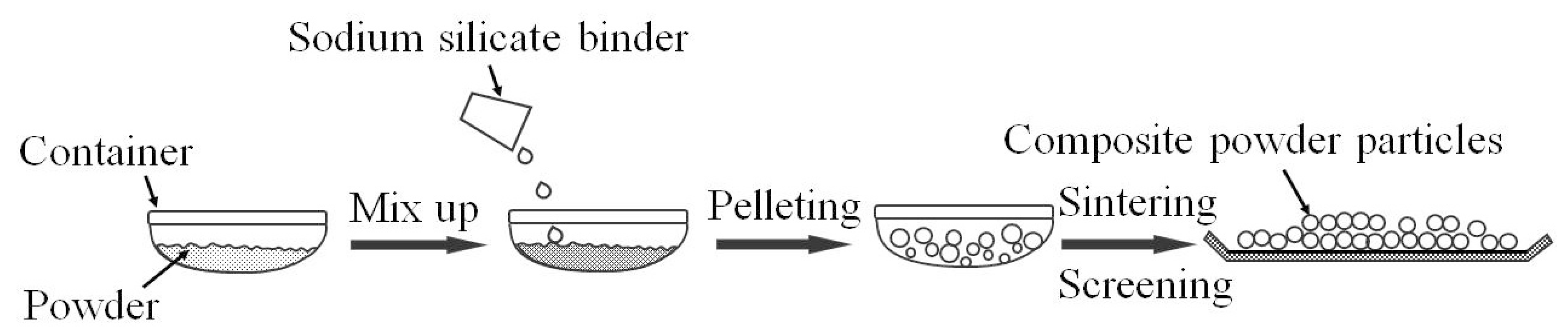
2.1. The Preparation of Composite Powder Particles

Composite powder particles (CPP) were prepared from a mixture of powdered components, such as high-carbon ferrochromium (FeCr70C8.0), ferrovanadium (FeV50A), ferrotitanium (FeTi30A), graphite chip, superfine aluminum dust, iron dust, etc. The processing course is shown in Figure 1.
Firstly, the powdered components were put in a container and stirred for at least half an hour. Next, 15–25 mL of sodium silicate binder with a Baume degree of 40 and modulus of 3.3 was added to 100 g of the mixture. The mixture was agitated for 20 min and wet evenly. Later, the container was rotated to pelletize the mixture into composite powder particles and dried at room temperature for an hour. The container was kept in the stove at 300–400 °C for 3 h. Subsequently, the sintered composite powder particles were screened through sieves of 10 mesh and 30 mesh, respectively. Finally, composite powder particles of sizes 0.5–1.5 mm were acquired. To study the effects of composite powder particles, the powder mixture (PM) containing the same powdered components without the binder as CPP was selected as the reference sample.

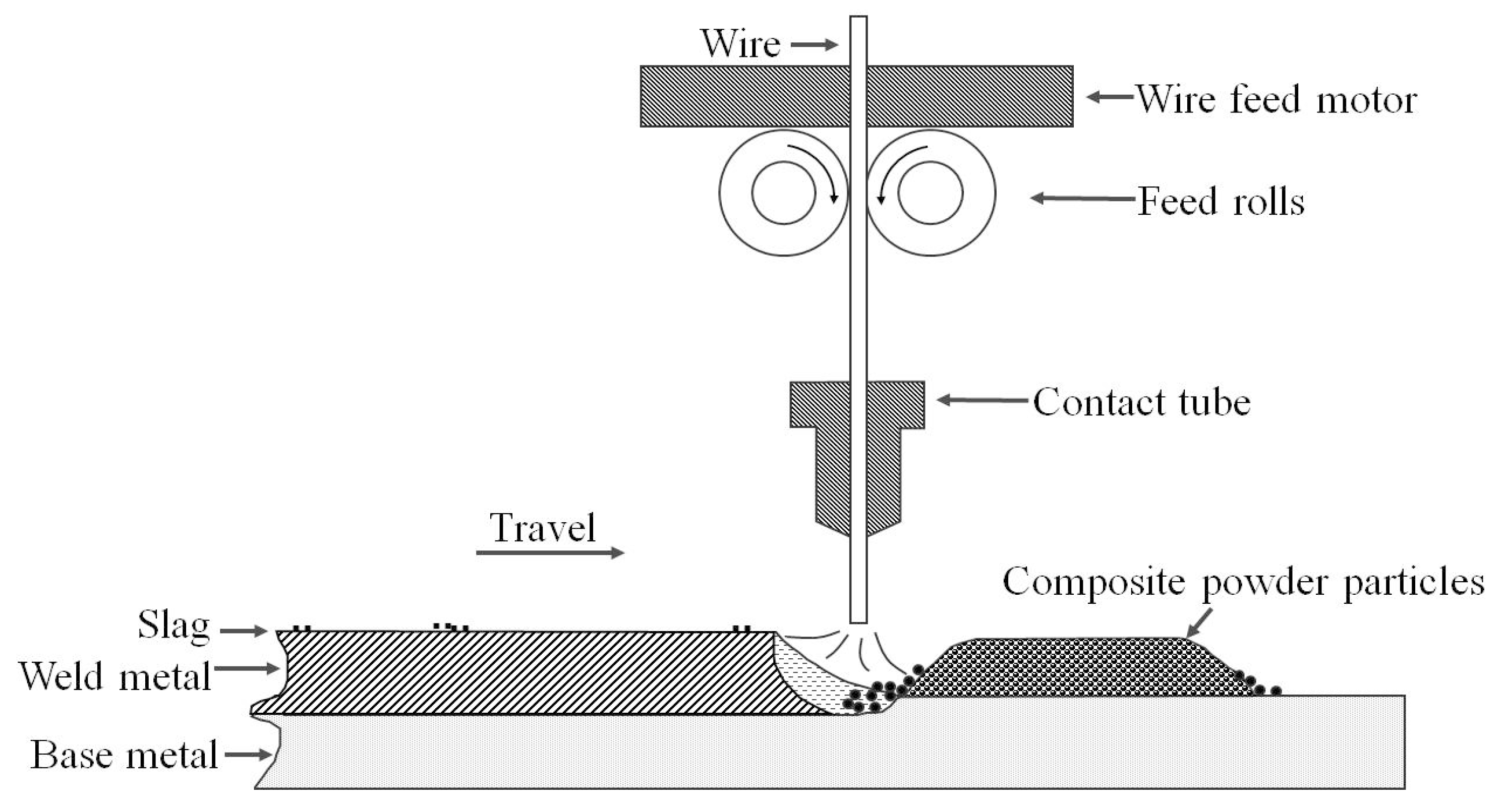
2.2. Welding Procedure

The prepared composite powder particles of constant mass were preset on weld beads along the welding direction. The schematic image is shown in Figure 2. An H08A solid wire with a diameter of 2.5 mm was chosen to be the arc carrier, and its chemical composition is shown in Table 1. The welding was performed on a ZD5-1000E direct current welding machine (Tangshan Kaiyuan Special Welding Equipment Co. Ltd, Tangshan, China) with the polarity designated as direct current electrode positive (DCEP) (reverse polarity). High chromium hardfacing alloys were deposited on base plates of dimensions 200 mm × 47 mm × 10 mm using self-shielded open arc welding. The welding parameters are shown in Table 2, and the travel speed of each sample is given in Table 3.
During the welding processes, molten drops of H08A solid wire and melts of composite powder particles were fused into a molten pool due to the intense heat applied by the arc. The pool solidified directly in the atmosphere and high chromium alloys were deposited on the base metals. To reduce the effect of dilution of base metals, high chromium hardfacing alloys with double layers were prepared. In contrast to the samples with CPP, hardfacing alloys deposited with the powder mixture having the same components as CPP, except for the sodium silicate binder, were also prepared in the same manner and used as a reference.
This research aimed to investigate the effects of travel speed on the microstructure and abrasion resistance of hardfacing alloys. The variation of the chemical composition of hardfacing alloys is given in Table 4. After welding, all the samples were cooled at room temperature and cut appropriately for the analysis of microstructure, bulk or microhardness, and abrasion resistance.

2.3. Microstructure of Hardfacing Alloys

Metallographic specimens of dimensions 12 mm × 10 mm × 25 mm were cut from the middle part of the welding beads using wire electrical discharge machining. The phase compositions of these specimens that were not etched after polishing were analyzed using a D/MAX2550VB X-ray diffractometer (XRD) (Rigaku inc., Tokyo, Japan) Next, the samples were etched with a 4% nital solution for 60 s. The microstructure of the hardfacing alloys was examined using an Axiovert40 MAT optical microscope (OM) (Carl Zeiss Co., Ltd., Jena, Germany), JSM-6360LV scanning electron microscope (SEM) (Japan Electronics Co. Ltd., Tokyo, Japan), and attached Oxford 7854 energy dispersive spectrometer (EDS) (Oxford instruments Ltd., Oxford, UK). The bulk hardness measurements were performed using the Rockwell hardness tester (Laizhou Huayin Testing Instrument Co., Ltd., Laizhou, China) (150 kg). Micro-hardness tests were conducted using a HMV-2 micro-hardness machine (Shanghai Tuming Optical Instrument Co., Ltd., Shanghai, China).
The dilution of base metals on hardfacing alloys was characterized by measuring the area of the vertical cross-section. The area of deposited metal (A) and that of the melted base metal (B), as shown in Figure 3, were measured, and the average area calculated from five samples was taken as the final value.
The dilution ratio, η = Area B/(Area A + Area B)

2.4. Abrasive Wear Test

Abrasive wear tests were performed on an MLS-225 wet sand rubber wheel testing machine (Chengxin Instrument Manufacture Co., Ltd., Zhangjiakou, China). The wear testing specimens of dimensions 57 mm × 25.5 mm × 6 mm were cut from the middle part of the welding beads. A mixture of water and quartz grain sand of the size 250–425 µm were taken as abrasive materials. The testing parameters were as follows: wheel diameter 178 mm, load 24.5 N, and wheel rotation speed 245 r/min. The initial weight, M0, and final weight, M1, were weighed, and the difference (M0–M1) between them was calculated to be the weight loss of the wear specimen (∆M). It was measured using an electronic precision balance.
Finally, the worn morphology of the hardfacing alloys was observed using a SEM to investigate their wear mechanism.

3. Results and Discussion

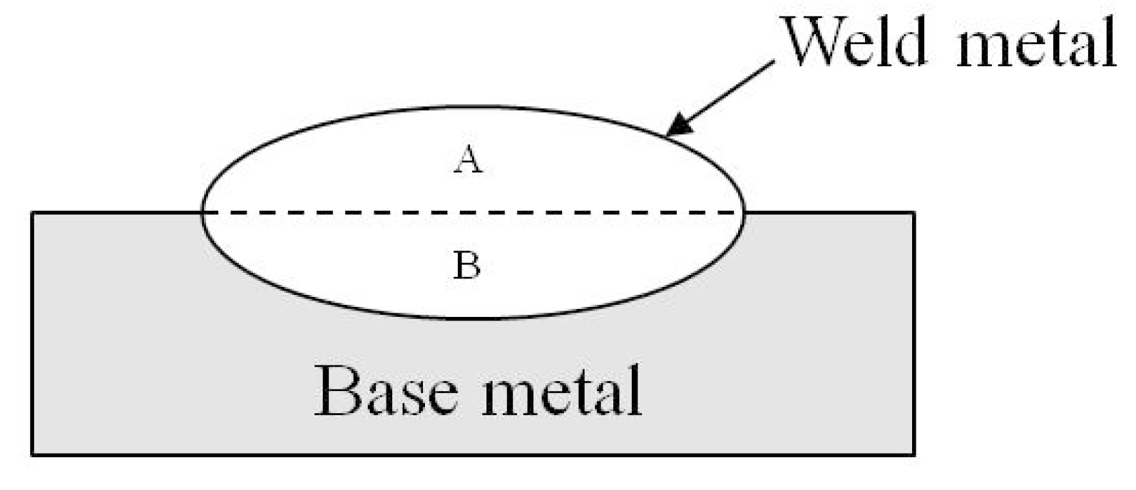
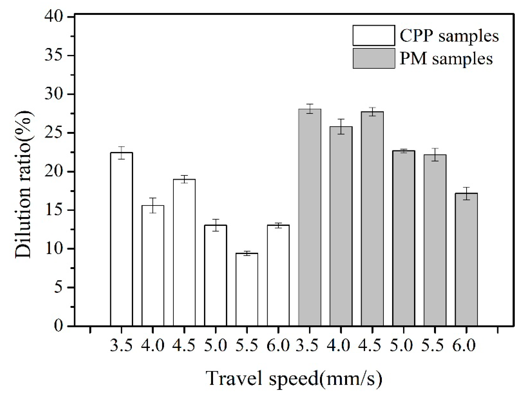
3.1. The Dilution Ratio of Base Metals

The welding metals were made of deposited metals and melted base metals of low carbon steel, as shown in Figure 2 and Figure 3. It can be concluded that the amount of melted base metals has a marked effect on the chemical composition of the welding metals due to the significant difference between them, especially for hardfacing alloys with a large amount of alloying elements. Hence, the high dilution ratio induced by the base metals can change the microstructure of the hardfacing alloy from hypereutectic to hypoeutectic and results in a huge difference between the values of abrasion resistance, which reduces the quality of the welding metals. The dilution level and resultant weld metal composition will depend on the volumetric filler metal and net arc [17]. However, a reduction in the dilution ratio of base metals remains a challenge for hardfacing alloys.
For some hardfacing samples with PM, porosity appears easily but to a small extent on the weld beads. During the open arc self-shielded welding process, the arc blow forced the light components such as graphite chips to be blown away from the arc column. This results in an insufficient formation of self-shielded gases and high oxide levels, causing porosity and cracks. The CPP were in complete contrast to PM as they showed no porosity on weld beads and different welding properties. The appearance of these weld beads was similar to those of self-shielded flux-cored wire. The binding function of sodium silicate on graphite and other powdered components drastically reduces the blow-off loss of light components such as graphite chips. It is concluded that the metallurgical reactions of the powdered components are complete, generating sufficient amounts of shielded gases that reduce the loss of alloying elements by oxidation, as can be seen from the composition shown in Table 4.
Figure 4 indicates that the dilution ratio of the hardfacing alloy with PM is much higher than that with CPP welding at the same travel speed. With an increase in the travel speed, the dilution ratio gets reduced gradually, lowering the melting mass of the base metals, despite some fluctuations at 4.0 mm/s. Although the total weight of the presetting powder is the same, the weight of the individual powdered particles is entirely different, and the arc blow easily repels the lighter particle from the arc column. The arc directly attacks the base metals, which leads to an increase in the melt. In contrast, the CPP contain a small amount of sodium silicate, which preferentially emitted electrons. This induces the arc to attack the CPP directly, thus reducing the dilution ratio of the base metal. Therefore, compared to PM, CPP with a binding agent are preferentially heated into a melt by the arc.
As shown in Figure 4, when the travel speed was 5.5 mm/s, the dilution ratio of the base metal for hardfacing alloys with CPP was 9.4%, but for those with PM it was 22.2%, which was more than twice the ratio of the CPP. The results in Table 4 and Figure 4 indicate that the composite powder particles have a positive effect on the dilution ratio in comparison with the powder mixture. This leads to an increase in the travel speed, which decreases heat input on the base metal as well as the composite powder particles. The melts show the characteristics of the component with higher chemical composition, leading to better precipitation of primary carbides from them.

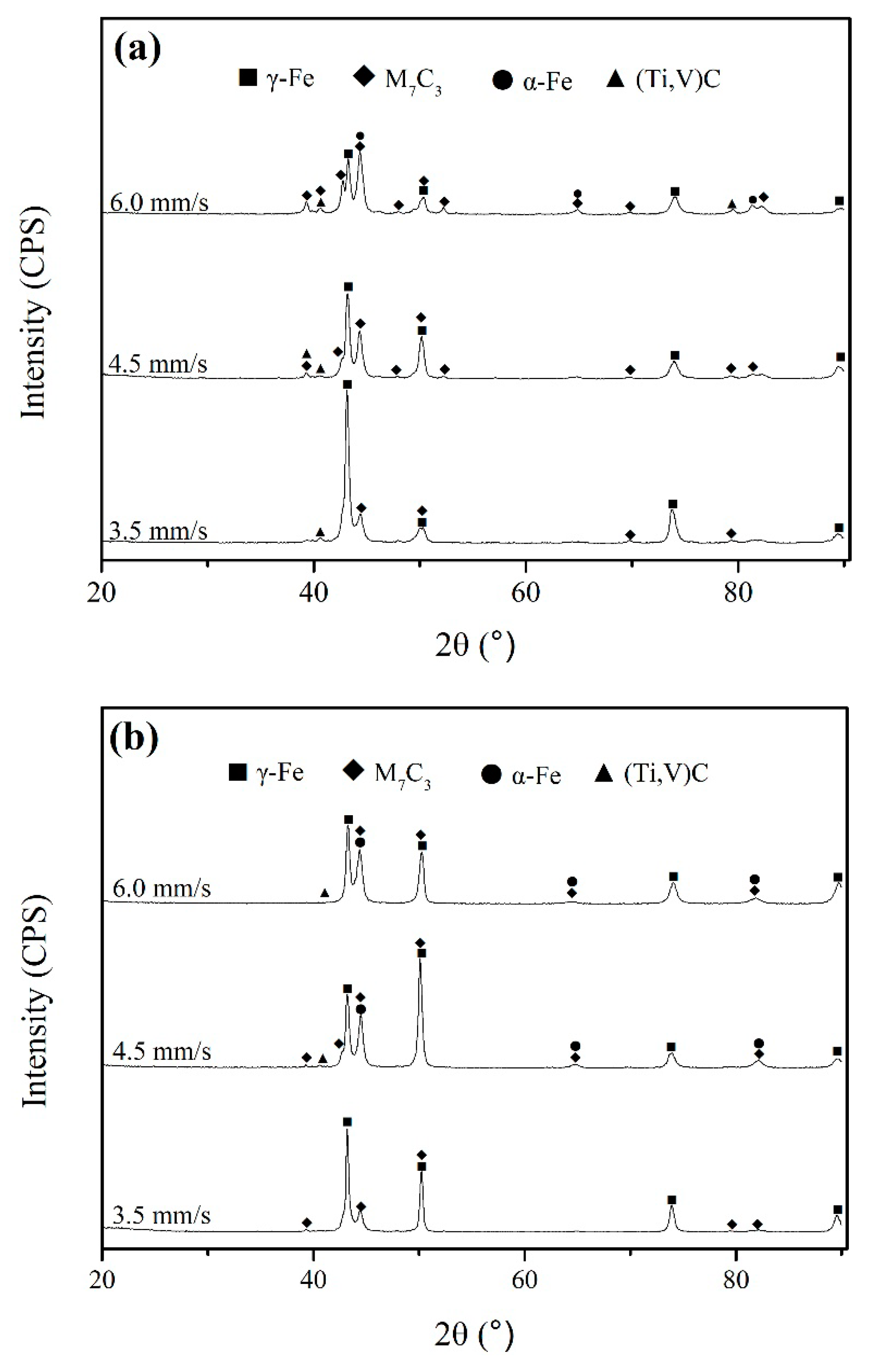
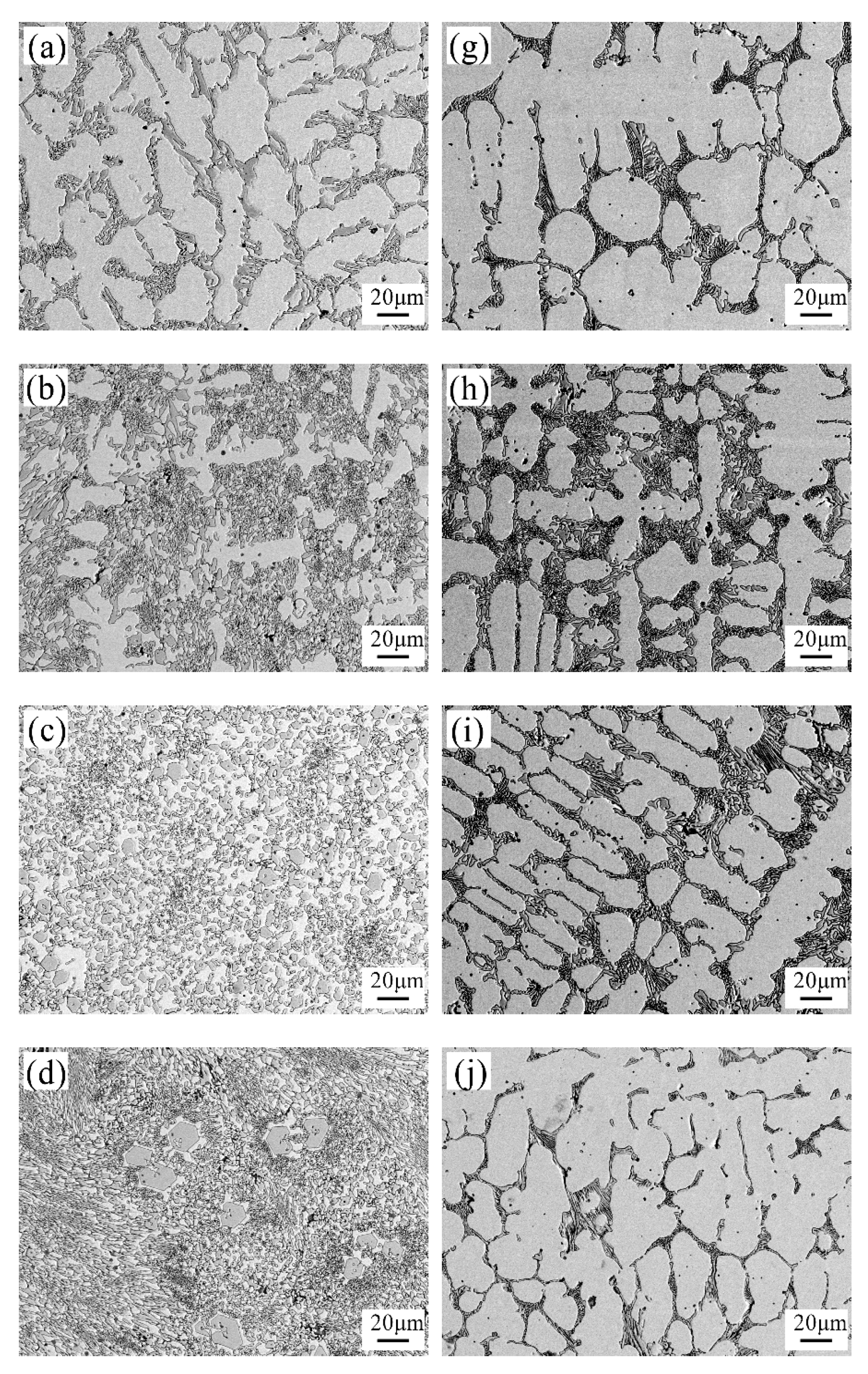
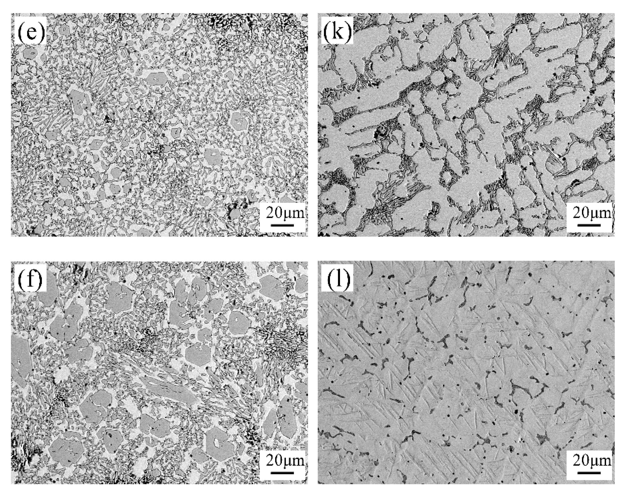
3.2. The Microstructure of Hardfacing Alloys

The X-ray diffraction patterns of hardfacing alloys with CPP and PM are shown in Figure 5a,b, respectively. It is seen from Figure 5a that the microstructure of hardfacing alloys with CPP consists of γ-Fe, M7C3, and (Ti, V) C. At a travel speed of 3.5 mm/s, the matrix consists of γ-Fe, and the diffraction peak intensity of the M7C3 phase shows that their volume fraction is not high. With the travel speed increasing from 4.5 to 6.0 mm/s, the intensity of the diffraction peak indicates that the volume fraction of the M7C3 phase increases, but that of γ-Fe decreases. It is obviously seen that the travel speed has a huge impact on the characteristic phases of hardfacing alloys with composite powder particles.
The X-ray diffraction patterns of hardfacing alloys with PM in Figure 5b shows that the diffraction peak intensity of γ-Fe is quite high at different travel speeds, which means that the volume fraction only varies slightly. The volume fraction of M7C3 increases initially and then decreases with the enhancement of travel speed. This shows that the travel speed has minor impacts on the microstructure of hardfacing alloys with powder mixture.
The microstructures of hardfacing alloys with CPP welding at different weld speeds are given in Figure 6a–f. It is observed that the matrix in the cellar shape is austenite, and the grey phases of discontinuous net-like shape are inter-granular carbides, based on the XRD results shown in Figure 5a. With the increase in the travel speed from 3.5 to 6.0 mm/s, the cellar austenite gets refined due to the reduction of heat input on the weld metals. The volume fraction of the inter-granular carbides rises initially and then drops, with the microstructure changing from the hypoeutectic to the hypereutectic form.
As shown in Figure 6d,e, the primary carbides in a hexagonal shape with micro-hardness of 1170 HV can be deemed as M7C3 phases based on the XRD patterns shown in Figure 5a. According to the Fe-C-Cr ternary phase diagram, the solidification phase transformation procedure can be described as follows: LL + M7C3 (primary) → γ + M7C3 (primary) → γ + M7C3 (primary) + α-Fe + M7C3 (secondary). As the morphology of carbides depends on the cooling rate and composition [18], the increase in the travel speed also changes the morphology by reducing the heat input on the weld metals. In general, the grains of weld metals can be refined as the solidification speed of the puddles is high. However, the grains of the primary M7C3 phase of hardfacing alloys with CPP are not refined according to the general law. They become larger, as shown in Figure 6d–f. This clearly indicates that the component supply is sufficient enough to meet the requirements of grain growth under faster solidification conditions. This contributes to the decrease in the dilution ratio of base metals and higher concentration of alloying welding melts, which subsequently leads to the rapid growth of primary M7C3 phases in open arc welding conditions with reduced migration and diffusion of alloying atoms.
The grains of hardfacing alloys with PM are refined with the increase in travel speed due to the reduced heat input on weld metals, as can be seen in Figure 6g–k. In addition, an irregular variation of inter-granular carbides is observed. The initial increase in the volume fraction of inter-granular carbides is caused by the carbon atoms accommodated in austenite that gets reduced with the decrease in the volume fraction of austenite at high carbon levels. Subsequently, the variation in the volume fraction of inter-granular carbide is attributed to the combined action of grain refinement and varied austenite content, as a result of the considerable decrease in the transferred alloy with increasing travel speed, which also affects the carbon content, as observed in Table 4.
The EDS results of the hardfacing alloys with CPP, as shown in Figure 7a, and with PM, as shown in Figure 7b, at 5.0 mm/s are tabulated in Table 5. The hardfacing alloys with CPP had alloying elements such as Cr and V in the regions under investigation. Although the carbon content varied sharply in Regions a1 and a4, the alloys of Cr and V showed only a slight variation. Among the Regions a1, a2, a3, and a4, the element Ti was detected only in Region a2, while Cr and V were remarkably seen in Regions a1, a2, and a3. The (Ti,V)C phases were precipitated in these regions. The phases in Regions a1 and a3 are confirmed to be the primary M7C3 and secondary M7C3, respectively. Moreover, the phase present in Region a4 is considered to be the ferrite matrix, based on the results shown in Table 5 and Figure 5a. Furthermore, this indicates that the alloying element is not only dissolved in ferrite or austenite matrices, but also appears in carbides such as M7C3, where M represents Fe, Cr, and V.
For the hardfacing alloys with PM shown in Figure 7b, the concentrations of Cr and V in Region b2 are much higher than in Regions b1 and b3. The matrix in Region b1 can be deemed as austenite, the grey phase in Region b3 is ferrite, and the phases in Region b2 are identified as inter-granular M7C3 based on the results of XRD patterns shown in Figure 5b.
From the carbide morphology shown in Figure 6a–l, and the results shown in Table 4, it is observed that the CPP bonded with sodium silicate have a higher transitional alloying element coefficient under self-shielded open arc welding condition compared to PM, although the mass preset on the weld beads is the same. This increases the utilization ratio of alloying elements and reduces the consumption of hardfacing alloys.

3.3. Abrasion Resistance of Hardfacing Alloys

The micro-hardness curves of hardfacing alloys along vertical profiles are shown in Figure 8. It is seen that the micro-hardness of hardfacing alloys with CPP is much higher than those with PM, with its average value being more than 1.5 times the value of the other. The highest hardness value is 1061 HV, which is almost equal to that of the primary hard phases that appeared in the high chromium alloys.
Although the constituents in CPP and PM are the same, except for the bonding agent, their micro-hardness values show remarkable variance, which indicates that their properties are entirely different. Generally, CPP bonded with sodium silicate significantly improve the abrasion resistance of hardfacing alloys.
From the results shown in Figure 8, it is obvious that the micro-hardness curve of hardfacing alloy layers with PM shows nearly the same variation, which indicates that the travel speed has less impact on the microstructure. For hardfacing alloy layers with CPP, the micro-hardness curve shows higher fluctuation, especially over 800 HV, which indicates the appearance of primary M7C3 phases and reduced effects of the dilution ratio induced by base metals. It is observed that the uniformity of micro-hardness at every hardfacing layer is affected, although the variation is lowered with the elevation of travel speed.
The bulk hardness and mass loss upon wearing of hardfacing alloys are shown in Figure 9. The hardfacing alloys with CPP exhibit excellent abrasion resistance, which is correlated to the high value of bulk hardness. The bulk hardness was initially low due to the high dilution ratio of base metals and was enhanced subsequently with the continuous decrease in the dilution ratio and precipitation of primary M7C3 phases, which played a major role in improving the abrasion resistance of hardfacing alloys [19,20]. When their bulk hardness rose to 58.1 HRC, the wear mass loss was reduced to 0.019 g, which is lower than the high chromium alloys deposited by self-shielded open arc welding [21]. This clearly indicates that the abrasion resistance of hardfacing alloys with composite powder particles is comparable to the resistance offered by flux-cored wire open arc welding, although the processing technology of the latter is more straightforward, faster, and economical.
The bulk hardness of hardfacing alloys with PM is below 46 HRC, which is lower, and the wear mass loss is much higher and nearly triple, compared to that of CPP. It is seen that the bonding shown by the powder components leads to a significant improvement in the abrasion resistance.
The scratches and pits on the surface of the weld metals in the hardfacing alloys containing CPP indicate that their wear mechanisms involve the micro-cutting of abrasive particles and micro-spalling, respectively [22,23], as can be clearly seen from Figure 10a–c. With the increase in the travel speed, the scratches become discontinuous, pits appear due to the high volume fraction of primary M7C3 phases, and the eutectic carbides are not strong enough to resist the attack of rigid abrasive particles, as observed in Figure 10c. The wear mass loss produced by micro-spalling is larger and appears in the area of the eutectic, as seen from the results in Figure 6e, which is in contrast with Figure 10c.
Scratches are observed on the surface of powder mixture hardfacing alloys, as shown in Figure 10d–f. There are no pits, and the scratches are parallel to each other with no interruption. This explicitly indicates that the intra-granular carbides do not have much involvement in the improvement of abrasion resistance because the hardness of quartz grain was much higher than the samples with soft cellular austenite as the primary phase, as the latter is easily penetrable by abrasive particles [24,25], and their wear mechanism involves the micro-cutting of these particles.
In general, the wear resistance is determined by the size, shape, distribution, matrix microstructure, and chemical composition of the carbides, as well as the wear test conditions [26]. Those with hard primary phases show better abrasion resistance [27,28]. The experimental results for hardfacing alloys with composite powder particles indicate that the increase in travel speed not only contributes to the decrease in the dilution ratio of base metals on hardfacing alloys but also improves the volume fraction of primary M7C3-type carbides [29,30], which is advantageous for the improvement of abrasive resistance.

4. Conclusions

In this study, the composite powder particles preset on base metals were fused with a solid wire by the intense heat provided by the arc to form a melt. An X-ray diffractometer, scanning electron microscopy, and energy dispersive spectrometer were employed to investigate the effects of travel speed on the microstructure and abrasion resistance. It was found that the microstructure of the hardfacing alloys with composite powder particles or powder mixture consists of γ-Fe, M7C3, and (Ti, V) C. With an increase in the travel speed, the microstructure with composite powder particles changes from the hypoeutectic to the hypereutectic form, but the one with the powder mixture remains hypoeutectic throughout. For hardfacing alloys with composite powder particles, the increasing travel speed not only contributes to the reduction of the dilution ratio of the base metals on these alloys but also deliberately improves the volume fraction of primary M7C3-type carbides, which is advantageous for the improvement of abrasive resistance. The corresponding study also indicated that the bonding function executed by the powder components led to a significant increase in the abrasion resistance and improved the utilization ratio of the alloying elements. Further studies suggested the primary wear mechanisms of micro-cutting and micro-spalling.

Author Contributions

Conceptualization, J.G. and H.Y.; data curation, H.Y.; formal analysis, H.Y. and J.G.; investigation, H.Y.; methodology, H.Y., S.C., C.L., and H.H.; Project administration, J.G.; resources, J.G.; supervision, J.G.; writing—original draft, H.Y.; writing—review and editing, J.G. and H.Y. All authors have read and agreed to the published version of the manuscript.

Funding

This research was funded by the Natural Science Foundation of Hunan Province, grant number 2015JJ5031.

Conflicts of Interest

The authors declare no conflict of interest.

References

  1. Correa, E.O.; Alcantara, N.G.; Tecco, D.G.; Kumar, R.V. The relationship between the microstructure and abrasive resistance of a hardfacing alloy in the Fe-Cr-C-Nb-V system. Metall. Mater. Trans. A 2007, 38, 1671–1780. [Google Scholar] [CrossRef]
  2. Wang, X.H.; Han, F.; Qu, S.Y.; Zou, Z.D. Microstructure of the Fe-based hardfacing layers reinforced by TiC-VC-Mo2C particles. Surf. Coat. Techol. 2008, 202, 1502–1509. [Google Scholar] [CrossRef]
  3. Rafi, H.K.; Ram, G.D.J.; Phanikumar, G.; Rao, K.P. Microstructure and Properties of Friction Surfaced Stainless Steel and Tool Steel Coatings. Mater. Sci. Forum 2010, 638–642, 864–869. [Google Scholar] [CrossRef]
  4. Srikarun, B.; Muangjunburee, P. The effect of iron-based hardfacing with chromium powder addition onto low carbon steel. Mater. Today Proc. 2018, 5, 9272–9280. [Google Scholar] [CrossRef]
  5. Morsy, M.; El-Kashif, E. The effect of microstructure on high-stress abrasion resistance of Fe-Cr-C hardfacing deposits. Weld. World 2014, 58, 491–497. [Google Scholar] [CrossRef]
  6. Sapate, S.G.; Ramarao, A.V. Erosive wear behaviour of weld hardfacing high chromium cast irons: Effect of erodent particles. Tribol. Int. 2006, 39, 206–212. [Google Scholar] [CrossRef]
  7. Dilawary, S.A.A.; Motallebzadeh, A.; Houdkova, S.; Medlin, R.; Haviar, S.; Lukac, F.; Afzal, M.; Cimenoglu, H. Modification of M2 Hardfacing: Effect of Molybdenum Alloying and Laser Surface Melting on Microstructure and Wear Performance. Wear 2018, 404, 111–121. [Google Scholar] [CrossRef]
  8. Sha, C.K.; Lin, J.C.; Tsai, H.L. The impact characteristics of Ti–6Al–4V plates hardfacing by laser alloying NiAl+ZrO2 powder. J. Mater. Process. Technol. 2003, 140, 197–202. [Google Scholar] [CrossRef]
  9. Zahiri, R.; Sundaramoorthy, R.; Lysz, P.; Subramanian, C. Hardfacing using ferro-alloy powder mixtures by submerged arc welding. Surf. Coat. Technol. 2014, 260, 220–229. [Google Scholar] [CrossRef]
  10. Liu, D.; Liu, R.; Wei, Y. Effects of titanium additive on microstructure and wear performance of iron-based slag-free self-shielded flux-cored wire. Surf. Coat. Technol. 2012, 207, 579–586. [Google Scholar] [CrossRef]
  11. Shen, S.; Oguocha, I.N.A.; Yannacopoulos, S. Effect of heat input on weld bead geometry of submerged arc welded ASTM A709 Grade 50 steel joints. J. Mater. Process. Technol. 2012, 212, 286–294. [Google Scholar] [CrossRef]
  12. Yuksel, N.; Sahin, S. Wear behavior–hardness–microstructure relation of Fe–Cr–C and Fe–Cr–C–B based hardfacing alloys. Mater. Des. 2014, 58, 491–498. [Google Scholar] [CrossRef]
  13. Zhang, A.F.; Xing, J.D.; Fang, L.; Su, J.Y. Inter-phase corrosion of chromium white cast irons in dynamic state. Wear 2004, 257, 198–204. [Google Scholar] [CrossRef]
  14. Berns, H. Comparison of wear resistant MMC and white cast iron. Wear 2003, 254, 47–54. [Google Scholar] [CrossRef]
  15. Xing, J.D.; Gao, Y.M.; Wang, E.Z.; Bao, C.G. Effect of phase stability on the wear resistance of white cast iron at 800 C. Wear 2002, 252, 755–760. [Google Scholar] [CrossRef]
  16. Aso, S.; Goto, S.; Komatsu, Y.; Hartono, W. Sliding wear of graphite crystallized chromium white cast iron. Wear 2001, 250, 511–517. [Google Scholar] [CrossRef]
  17. Banovic, S.W.; DuPont, J.N.; Marder, A.R. Dilution control in gas-tungsten-arc welds involving superaustenitic stainless steels and nickel-based alloys. Metall. Mater. Trans. B 2001, 32, 1171–1176. [Google Scholar] [CrossRef]
  18. Pawar, S.; Mukhopadhyay, G. Metallurgical and Tribological Evaluation of Fe-Cr-C Hardfacing Alloys. J. Fail. Anal. Prev. 2018, 18, 868–876. [Google Scholar] [CrossRef]
  19. Badisch, E.; Mitterer, C. Abrasive wear of high speed steels: Influence of abrasive particles and primary carbides on wear resistance. Tribol. Int. 2003, 36, 765–770. [Google Scholar] [CrossRef]
  20. Bergman, F.; Hedenqvist, P.; Hogmark, S. The influence of primary carbides and test parameters on abrasive and erosive wear of selected PM high speed steels. Tribol. Int. 1997, 30, 183–191. [Google Scholar] [CrossRef]
  21. Jiang, M.; Li, Z.X.; Wang, Y.J.; Shi, Y.W.; Jiang, J.M.; Li, X.B. Effect of vanadium on microstructures and properties of Fe-Cr-C self-shielded metal cored hardfacing alloys. Sci. Technol. Weld. Join. 2008, 13, 114–117. [Google Scholar] [CrossRef]
  22. Ren, S.; Zhu, J. The effect of substitutional alloying elements on the impact wear rate of medium carbon steels related to delamination and quasi-nanometer wear mechanisms. Mater. Sci. Eng. A 2011, 528, 7020–7023. [Google Scholar] [CrossRef]
  23. Ren, S.; Zhu, J. Wear mechanisms and hardness thresholds under repeated impact contact loading. Sci. China Technol. Sci. 2017, 61, 124–128. [Google Scholar] [CrossRef]
  24. Oo, H.Z.; Muangjunburee, P. Wear behaviour of hardfacing on 3.5% chromium cast steel by submerged arc welding. Mater. Today Proc. 2018, 5, 9281–9289. [Google Scholar] [CrossRef]
  25. Zhg, M.; Li, M.; Wang, J. Study on Composition, Microstructure and Wear Behavior of Fe-B-C Wear-Resistant Surfacing Alloys. J. Mater. Eng. Perform. 2017, 26, 6182–6192. [Google Scholar] [CrossRef]
  26. Buchely, M.F.; Gutierrez, J.C.; Leon, L.M.; Toro, A. The effect of microstructure on abrasive wear of hardfacing alloys. Wear 2005, 259, 52–61. [Google Scholar] [CrossRef]
  27. Gong, J.X.; Tang, T.S.; Xiao, Y.F. Effect of WC/W2C on the microstructure and abrasion resistance of high-boron hardfacing alloys. Acta Metall. Sinica (Engl. Lett.) 2010, 23, 439–445. [Google Scholar] [CrossRef]
  28. Chatterjee, S.; Pal, T.K. Wear behaviour of Hardfacing Deposits on Cast Iron. Wear 2003, 255, 417–425. [Google Scholar] [CrossRef]
  29. Liu, Y.F.; Xia, Z.Y.; Han, J.M. Microstructure and wear behavior of (Cr,Fe)7C3 reinforced composite coating produced by plasma transferred arc weld-surfacing process. Surf. Coat. Technol. 2006, 201, 863–867. [Google Scholar] [CrossRef]
  30. Filipovic, M.; Romhanji, E.; Kamberovic, Z. Chemical Composition and Morphology of M7C3 Eutectic Carbide in High Chromium White Cast Iron Alloyed with Vanadium. ISIJ Int. 2012, 52, 2200–2204. [Google Scholar] [CrossRef] [Green Version]
Figure 1. The processing course of composite powder particles.
Metals 10 00740 g001
Figure 2. Schematic image of open arc welding with composite powder particles.
Metals 10 00740 g002
Figure 3. Schematic image of hardfacing alloy layers.
Metals 10 00740 g003
Figure 4. The dilution ratio of base metals on hardfacing alloys with composite powder particles (CPP) and powder mixture (PM).
Metals 10 00740 g004
Figure 5. XRD patterns of hardfacing alloys (a) with CPP; (b) with PM.
Metals 10 00740 g005
Figure 6. Microstructure of hardfacing alloys (af) with CPP; (gl) with PM; (a,g) 3.5 mm/s; (b,h) 4.0 mm/s; (c,i) 4.5 mm/s; (d,j) 5.0 mm/s; (e,k) 5.5 mm/s; (f,l) 6.0 mm/s.
Metals 10 00740 g006aMetals 10 00740 g006b
Figure 7. SEM carbide image of hardfacing alloys at welding speed 5.0 mm/s (a) with CPP; (b) with PM.
Metals 10 00740 g007
Figure 8. Micro-hardness curves of hardfacing alloys along vertical profile.
Metals 10 00740 g008
Figure 9. Bulk hardness and wear mass loss of hardfacing alloys.
Metals 10 00740 g009
Figure 10. Worn morphology of hardfacing alloys (ac) with composite powder particles; (df) with powder mixture; (a,d) 3.5 mm/s; (b,e) 4.5 mm/s; (c,f) 5.5 mm/s.
Metals 10 00740 g010
Table 1. Chemical composition of solid wire H08A (wt%).
MaterialsCSiMnSPFe
H08A0.100.120.22≤0.02≤0.02Balance
Table 2. Welding parameters of hardfacing alloys.
ParametersCurrent(A)Voltage(V)Wire Extension(mm)Wire Feed Rate (mm/s)
410273045
Table 3. Travel speed of hardfacing samples.
SamplesComposite Powder ParticlesPowder Mixture
Travel speed (mm/s)1 #2 #3 #4 #5 #6 #1 #2 #3 #4 #5 #6 #
3.54.04.55.05.56.03.54.04.55.05.56.0
Table 4. Chemical compositions of hardfacing alloys (wt%).
AlloysCCrTiVFe
Composite powder particles2.3–2.99.0–13.90.1–0.31.4–1.9Balance
Powder mixture1.4–2.72.7–9.10–0.10.3–1.4Balance
Table 5. Micro-area chemical composition in high chromium hardfacing alloys (atom fraction, %).
PointAtom Fraction (%)abs. Error (%) [1 Sigma]
a1a2a3a4b1b2b3
C32.9334.1233.6817.1313.2940.6917.8219.71
Ti--1.19----------0.17
V3.702.253.593.300.424.020.680.92
Cr33.4821.0629.8331.336.4621.967.700.22

