Noise Reduction Potential of Cellular Metals

Institute for Materials, TU Braunschweig, Langer Kamp 8, Braunschweig D-38106, Germany
*
Author to whom correspondence should be addressed.
Metals 2012, 2(2), 195-201; https://doi.org/10.3390/met2020195
Submission received: 15 April 2012
/
Revised: 29 May 2012
/
Accepted: 7 June 2012
/
Published: 12 June 2012
(This article belongs to the Special Issue Selected Papers from the 7th International Conference on Porous Metals and Metallic Foams (MetFoam 2011))
Abstract
:Rising numbers of flights and aircrafts cause increasing aircraft noise, resulting in the development of various approaches to change this trend. One approach is the application of metallic liners in the hot gas path of aero-engines. At temperatures of up to 600 °C only metallic or ceramic structures can be used. Due to fatigue loading and the notch effect of the pores, mechanical properties of porous metals are superior to the ones of ceramic structures. Consequently, cellular metals like metallic foams, sintered metals, or sintered metal felts are most promising materials. However, acoustic absorption depends highly on pore morphology and porosity. Therefore, both parameters must be characterized precisely to analyze the correlation between morphology and noise reduction performance. The objective of this study is to analyze the relationship between pore morphology and acoustic absorption performance. The absorber materials are characterized using image processing based on two dimensional microscopy images. The sound absorption properties are measured using an impedance tube. Finally, the correlation of acoustic behavior, pore morphology, and porosity is outlined.
1. Introduction
Due to increasing traffic, many people are exposed to significant noise loads causing insomnia and other reactions, which impair health and productivity [1,2]. The rising number of flights and aircrafts causes an excessive air traffic noise increase. To change this development, various approaches have been developed to reduce the different noise sources like airframe noise, jet noise or engine noise. One approach to reduce this noise is the application of noise reducing liners in the hot gas path. Due to the elevated temperatures and high fatigue loading in this part of the aero-engine, conventional passive absorber materials cannot be used. Polymers are not able to bear the heat and brittle ceramic structures would crack due to the mechanical loading. Consequently, this study focuses on cellular metals, which can resist elevated temperatures as well as fatigue loading and, additionally, resemble geometrically conventional passive absorbers. Depending on the production processes, e.g., sintering of metal fibers [3], powder processing using a foaming agent [4], coating of polymer foams [5], or melt infiltration techniques [6], the characteristic dimensions of the porosity are usually in a range of 0.01 mm to 10 mm. Here, the relationship between sound absorption, pore size and porosity is analyzed and discussed. Finally, a conclusion is given suggesting suitable cellular metals for their application as liner materials.
2. Material Characterization
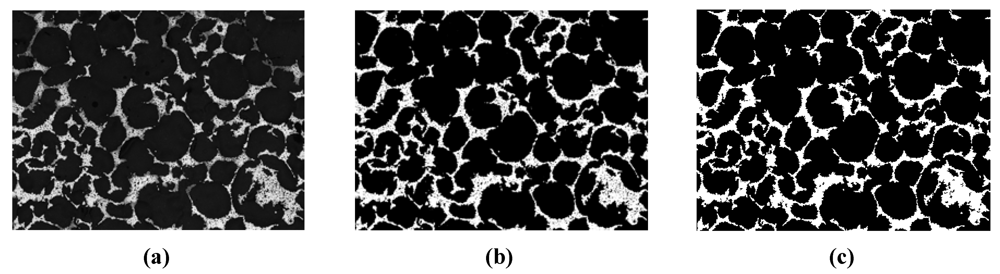
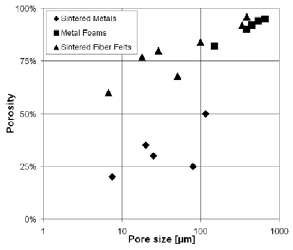
The characterization of the different cellular metals, see Table 1, is performed by using light microscopy. Therefore, all samples are embedded into a polymer, grinded and polished. The images must contain a representative area with a reasonable amount of pores, while details still contain a sufficient amount of pixels, see Figure 1(a). Since porous material is not homogenous, several images were taken to average results. In the first step, the microscopy images are binarized to generate black and white images; see Figure 1(b). In the second step, a smoothing routine is applied to remove areas of less than ten connected white pixels in a black area and vice versa to reduce noise from the image acquisition; see Figure 1(c). The pixel ratio of black and white pixels gives the porosity. Furthermore, a line segmenting method is applied to measure the average pore size [7,8]. Therefore, a lattice of parallel lines with a defined distance is superimposed on the image. The superimposing lines are rotated from 0° to an angle of 180° in 1°-step. The arithmetic average of the segment lengths in both phases is calculated for every angle. Black areas are pores and white areas are ligaments. The average segment lengths are plotted in a polar coordinate system forming an ellipse for each phase, see Figure 2. Due to symmetry, a half ellipse contains all information. If the obtained ellipses are circular, there is no preferred orientation of pores and an average pore size can be defined by averaging the segment lengths of each single angle. Average pore size and porosity of the analyzed materials are given in Table 1. In Figure 3, the porosity of the analyzed metallic absorber materials is plotted against the pore size. Sintered metals have comparably low porosity (20% to 50%) and the pore size ranges from some microns to around 120 µm. The porosity of sintered fiber felts is between 60% and 96%, the pore size ranges from some microns to some hundred microns. The porosity of metal foams is between 82% and 95% with pore sizes above 100 µm.
Figure 1.
Three steps of image pre-processing for the line segmenting method on MF-50. (a) Light microscope image; (b) Binarized image; (c) Structures < 10 pixels deleted.
Figure 1.
Three steps of image pre-processing for the line segmenting method on MF-50. (a) Light microscope image; (b) Binarized image; (c) Structures < 10 pixels deleted.

Figure 2.
Microstructure ellipses based on five different images of MF-50.
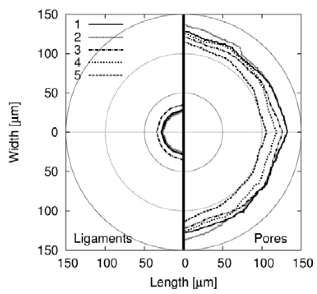
Figure 3.
Analyzed porous materials with properties shown in Table 1.
Figure 3.
Analyzed porous materials with properties shown in Table 1.


Table 1.
Material properties of metal foams (MF), sintered flakes (SF), sintered spheres (SS) sintered fiber felts (SFF).
| Material | Alloy | Porosity | Cell/pore size * | Average pore size |
|---|---|---|---|---|
| MF-50 | Haynes Alloy 230 | 82% | n/a | 121 ± 9 µm |
| MF-450 | NiFe22Cr22Al6 | 90% | 450 ± 45 µm | 380 ± 19 ** µm |
| MF-580 | NiFe22Cr22Al6 | 92% | 580 ± 60 µm | 445 ± 18 ** µm |
| MF-800 | NiFe22Cr22Al6 | 94% | 800 ± 80 µm | 538 ± 58 ** µm |
| MF-1200 | NiFe22Cr22Al6 | 95% | 1200 ± 120 µm | 656 ± 59 ** µm |
| SF-7.5 | Hastelloy X | 20% | 1.4~8 µm | 8.6 ± 1.2 µm |
| SF-20 | Hastelloy X | 35% | 12~25 µm | 22 ± 2 µm |
| SF-115 | Hastelloy X | 50% | 24~117 µm | 113 ± 13 µm |
| SS-25 | CuSn12 | 30% | 8~21 µm | 25 ± 2 µm |
| SS-80 | CuSn12 | 25% | 37~175 µm | 80 ± 12 µm |
| SFF-1 | Fe-22Cr-5Al (316 L) | 60 *% | 3~10 µm | 6.7 * µm |
| SFF-15 | Fe-22Cr-5Al (316 L) | 77 *% | 13~26 µm | 18 * µm |
| SFF-25 | Fe-22Cr-5Al (316 L) | 80 *% | 22~52 µm | 29 * µm |
| SFF-50 | Fe-22Cr-5Al (316 L) | 68 *% | 33~98 µm | 51 * µm |
| SFF-100 | Fe-22Cr-5Al (316 L) | 84 *% | 38~112 µm | 99 ± 8 µm |
| SFF-120 | Fe-22Cr-5Al (316 L) | 92% | n/a | 337 ± 83 µm |
| SFF-150 | Fe-22Cr-5Al (316 L) | 96% | n/a | 386 ± 14 µm |
* information of producer; ** values slightly influenced by hollow struts.
3. Acoustic Absorption Measurement Using an Impedance Tube
In an impedance tube, a noise generator emits a plane wave. The angle of incidence between the surface of the absorber material and the direction of the sound wave is 90°. Behind the absorber is a sonically hard wall, which reflects the sound waves. Two microphones measure the sound pressure of incident (pincident) and reflected (preflected) waves, which gives the factor of reflection r and the acoustic absorption α in dependence of the sample thickness [9]:

The sound pressure levels at the microphone positions x1 and x2 are defined as:

The microphone spacing ( ![Metals 02 00195 i005]() ) gives the transfer functions of incident wave H1, reflected wave H2, and entire interference field H3. p1incident is the incident part of p1 and p1reflected is the reflected part of p1. The same applies for p2.
) gives the transfer functions of incident wave H1, reflected wave H2, and entire interference field H3. p1incident is the incident part of p1 and p1reflected is the reflected part of p1. The same applies for p2.
 ) gives the transfer functions of incident wave H1, reflected wave H2, and entire interference field H3. p1incident is the incident part of p1 and p1reflected is the reflected part of p1. The same applies for p2.
Solving these equations gives the factor of reflection r which can be inserted in Eq.2 to calculate the acoustic absorption α [9]:

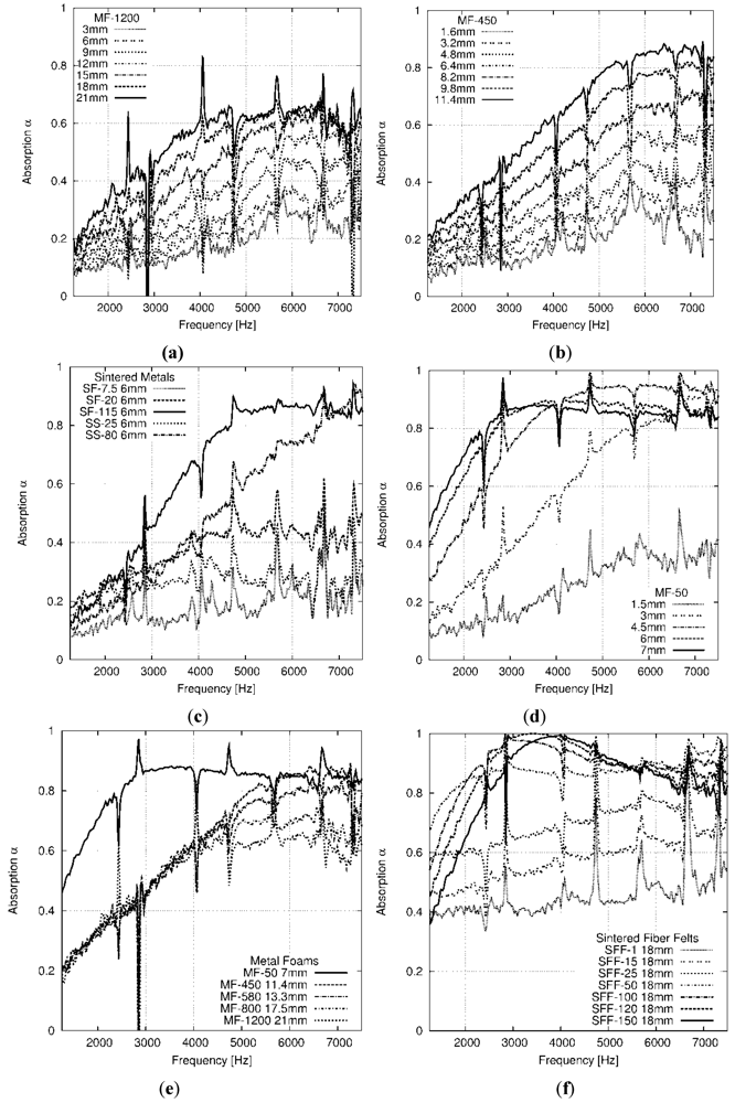
In this study, frequencies between 1 kHz and 7.5 kHz were analyzed. All samples were machined to fit precisely into the tube to avoid small gaps between sample and tube. Additionally, the tube was greased to avoid sample movement. The measurements were performed on single samples and sample stacks in front of an acoustic hard wall to analyze the influence of the absorber thickness, see Figure 4.
Figure 4.
Acoustic absorption of porous materials (detailed description of material properties in Table 1). (a) Absorption of MF-1200; (b) Absorption of MF-450; (c) Absorption of MF-50; (d) Absorption of different metal foams; (e) Absorption of different sintered metals; (f) Absorption of different metal fiber felts.

4. Discussion
All conducted measurements show poor absorption of low frequencies, supporting results of previous studies on passive absorbers [10]. At higher frequencies, acoustic absorption of cellular metals can reach values of more than 90%. Figure 4(a)–(d) show, that materials with bigger pores need thicker absorbers to reach high acoustic absorption in comparison to materials with smaller pores. Figure 4(e)−(f) show measurements of materials with similar pore sizes but different porosity. Materials with higher porosity show higher absorption due to reduced reflection of sound waves from the surface of the absorber material, since acoustic absorption can only be reached if the acoustic waves can couple into the absorber. Even if the porosity is high, low acoustic absorption results if the pores are too small, see Figure 4(f). Here, only cellular metals with pores taller than 50 µm showed satisfactory acoustic absorption. According to the law of Hagen-Poiseuille, the pore size is the dominant factor to influence the static air flow resistivity. The smaller the pores, the higher the static air flow resistivity and vice versa. In literature, the product of static air flow resistivity and absorber thickness is described as the most important parameter for acoustic absorption. The Delany-Bazley model is able to predict acoustic absorption using only static air flow resistivity and absorber thickness. Applicability is limited, since it is valid only for fibrous absorber with porosity close to one [11,12]. In aero-engines, the variation of the absorber thickness is limited. The maximum thickness is restricted due to the available space and the minimum thickness is defined by the requested material strength. Consequently, static air flow resistivity or pore size must be considered when selecting liner materials, respectively. Here, material with high porosity and pores taller than 50µm had the best acoustic absorption. Note, that all tests were performed at 20 °C. At 600 °C, slightly different results are expected due to changing properties of air.
5. Conclusions
One approach to reduce noise of aero-engines is the application of liners in the core-engine. Due to temperatures of up to 600 °C and the mechanical load, only metallic materials like metal foams, sintered metals or sintered fiber felts can be used. Acoustic absorption can only be reached if sound waves can couple into the absorber. To reduce reflection of sound waves from the absorber surface, the porosity of absorbers should be high, here 80% to 95%. For the analyzed frequency range, a minimum pore size of around 50 µm is needed. To reach similar sound absorption levels with material containing bigger pores, thicker absorber is needed. Consequently, metal foams or sintered metal fiber felts with pore sizes above 50 µm are the most suitable materials, since the porosity of sintered metals is too low. Note, that all tests were performed at room temperature.
Conflict of Interest
The authors declare no conflict of interest.
Acknowledgments
The authors would like to thank Alantum Europe GmbH and GKN sinter metals for providing sample materials. Financial support by the German federal state of Lower Saxony of the research program “Bürgernahes Flugzeug” is greatly appreciated.
References
- Haines, M.M.; Stansfeld, S.A.; Job, R.F.S.; Berglund, B. Chronic aircraft noise exposure, stress responses, mental health and cognitive performance in school children. Psychl. Med. 2001, 31, 265–277. [Google Scholar] [CrossRef]
- Franssen, E.; van Wiechen, C.; Nagelkerke, N.; Lebret, E. Aircraft noise around a large international airport and its impact on general health and medication use. Occup. Environ. Med. 2004, 61, 405–413. [Google Scholar] [CrossRef]
- Golosnoy, I.O.; Tan, J.C.; Clyne, T.W. Ferrous fibre network materials for jet noise reduction in aeroengines. Part I: Acoustic effects. Adv. Eng. Mater. 2008, 10, 192–200. [Google Scholar]
- Yu, C.-J.; Eifert, H.H.; Banhart, J.; Baumeister, J. Metal foaming by a powder metallurgy method: Production, properties and applications. Mater. Res. Innovat. 1998, 2, 181–188. [Google Scholar] [CrossRef]
- Pickering, S. Inco invests in its nickel future at Clydach. Met. Powder Rep. 1998, 53, 24–27. [Google Scholar]
- Brothers, A.; Scheunemann, R.; de Fouw, J.; Dunand, D. Processing and structure of open-celled amorphous metal foams. Scripta. Mater. 2005, 52, 335–339. [Google Scholar] [CrossRef]
- Hinze, B.; Rösler, J. Characterization of open-pored metals using image processing. In Characterization of Minerals, Metals and Materials; Hwang, J.-Y., Monteiro, S.N., Bai, C.-G., Carpenter, J., Cai, M., Firrao, D., Kim, B.-G., Eds.; John Wiley & Sons: Hoboken, NJ, USA, 2012; pp. 185–192. [Google Scholar]
- Hinze, B.; Rösler, J.; Schmitz, F. Production of nanoporous superalloy membranes by load-free coarsening of γ′-precipitates. Acta Mater. 2011, 59, 3049–3060. [Google Scholar] [CrossRef]
- Akustik—Bestimmung des Schallabsorptionsgrades und der Impedanz in Impedanzrohren—Teil 2: Verfahren mit Übertragungsfunktion. EN ISO 10534-2, Brussels, Belgium, 2001.
- Schirmer, W.; Lotze, E. Technischer Lärmschutz, 2nd ed; Springer: Berlin, Germany, 2006; pp. 208–216. [Google Scholar]
- Delany, M.E.; Bazley, E.N. Acoustical properties of fibrous absorbent materials. Appl. Acoust. 1970, 3, 105–116. [Google Scholar] [CrossRef]
- Allard, J.-F. New empirical equations for sound propagation in rigid frame fibrous materials. J. Acoust. Soc. Am. 1992, 91, 3346–3353. [Google Scholar] [CrossRef]
© 2012 by the authors; licensee MDPI, Basel, Switzerland. This article is an open-access article distributed under the terms and conditions of the Creative Commons Attribution license (http://creativecommons.org/licenses/by/3.0/).
Share and Cite
MDPI and ACS Style
Hinze, B.; Rösler, J.; Lippitz, N. Noise Reduction Potential of Cellular Metals. Metals 2012, 2, 195-201. https://doi.org/10.3390/met2020195
AMA Style
Hinze B, Rösler J, Lippitz N. Noise Reduction Potential of Cellular Metals. Metals. 2012; 2(2):195-201. https://doi.org/10.3390/met2020195
Chicago/Turabian StyleHinze, Björn, Joachim Rösler, and Nicolas Lippitz. 2012. "Noise Reduction Potential of Cellular Metals" Metals 2, no. 2: 195-201. https://doi.org/10.3390/met2020195