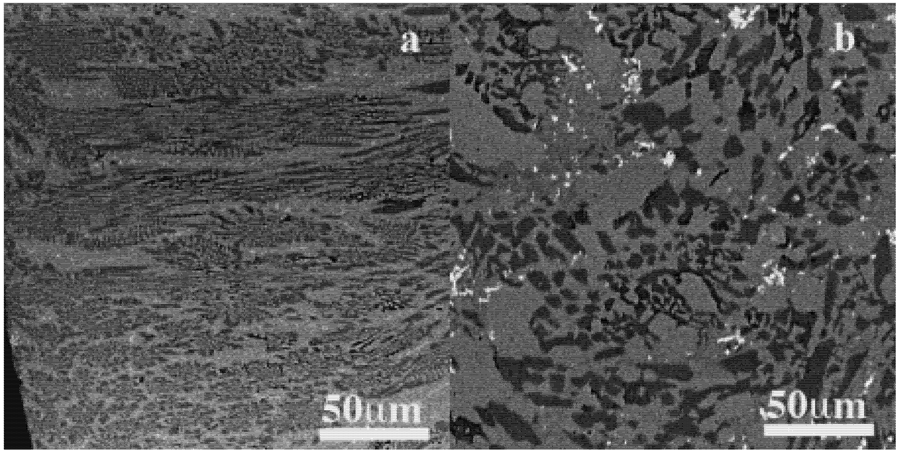
2.1. Microstructure of Injected Fe40Ni38Mo6B18 Alloy
Figure 2 shows the SEM-BEI micrographs of Fe
40Ni
38Mo
4B
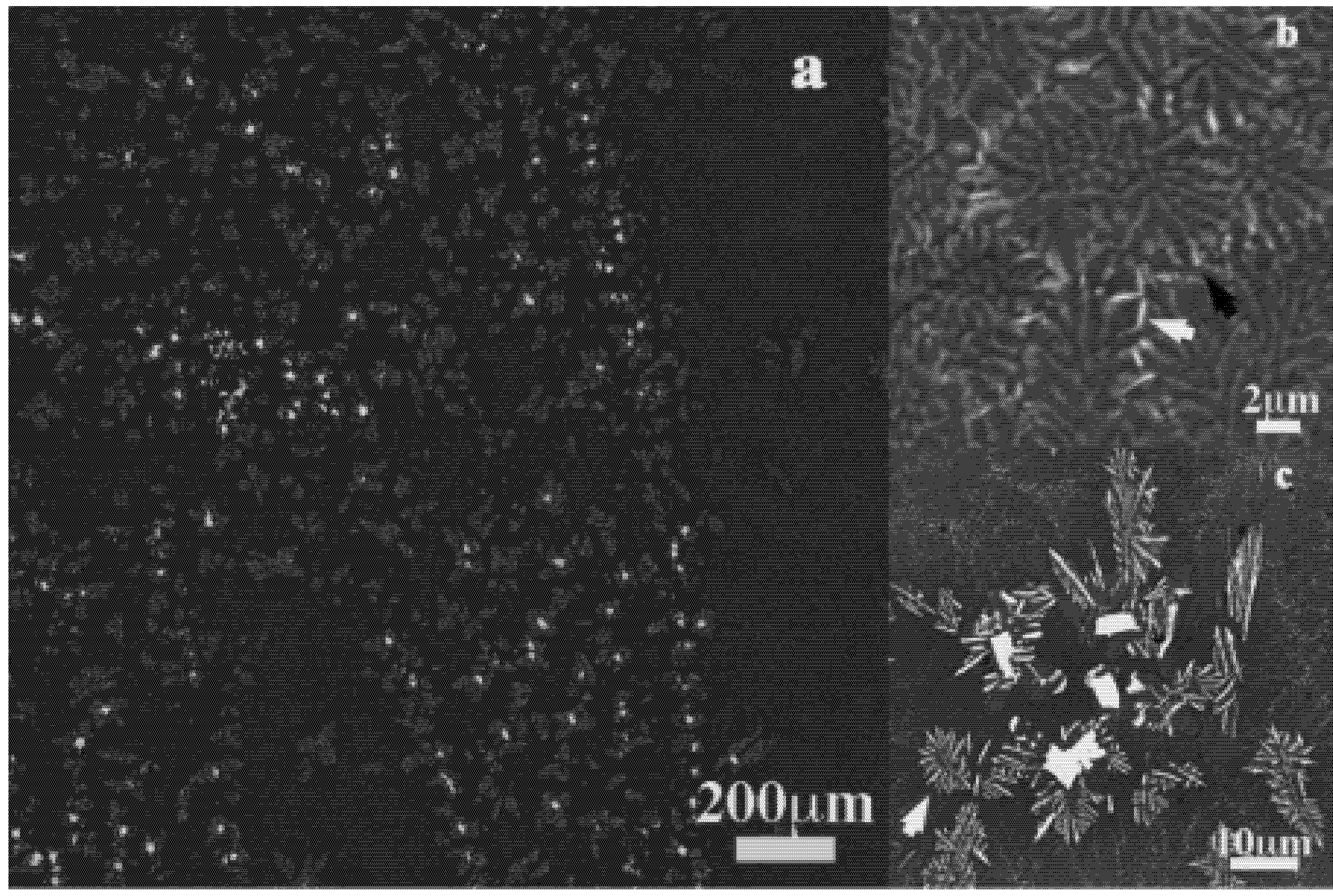
18 plate ingot cross section. It is crystalline with a major eutectic structure containing white contrast precipitates and dendrites. These latter are formed on linear paths that are probably linked to the turbulent movement of the melt during the casting (
Figure 2a). Details of the eutectic grains (
Figure 2b), with one phase appearing as a needle are shown (white arrowed) along with dots (black arrowed). The dot is presumably the same needle’s front view. The dendrites and the plate-like precipitates embedded in the eutectic matrix are also magnified in
Figure 2c. The eutectic structure is composed of cubic (c) (Fe, Ni) and orthorhombic (o) (Fe, Ni, Mo)
3B phases, the nature of the plate precipitates are much complex. It has been characterized as tetragonal (t) Fe-Mo sigma phase [
9], however c- Fe
2Mo
3 phase and other unknown Mo-rich phases can match. The dendrite axis is also tricky because of its content in boron. They can be described as c-Fe
xNi
23 − x(Mo)B
6 or/and B-Mo rich phases. A detailed study of the crystalline phases in Fe
40Ni
38Mo
4B
18 alloy will be published further elsewhere.
Figure 2.
(a) SEM-BEI micrographs of Fe40Ni38Mo4B18 plate ingot sample processed by levitation; (b) Needle-like phase in the eutectic microstructure; (c) Plate-like crystals and dendrites embedded in the eutectic structure.
The microstructural inhomogeneity is likely inherent to levitation casting and injected melt casting produced by the unsteady solidification. However, for a homogeneous melt, the stream must have the same composition as the initial melt. The crystalline phases appearing on the paths are the growth of atomic clusters existing within the homogeneous areas due to cooling rate change if one considers that melt filets or filaments generated by the injection pressure have the same chemical composition. Thus, the growth of the crystal may be attributed to the low cooling rate due to higher fluidity, or low viscosity as d
T/d
t is proportional to 1/η; η is the viscosity [
10].
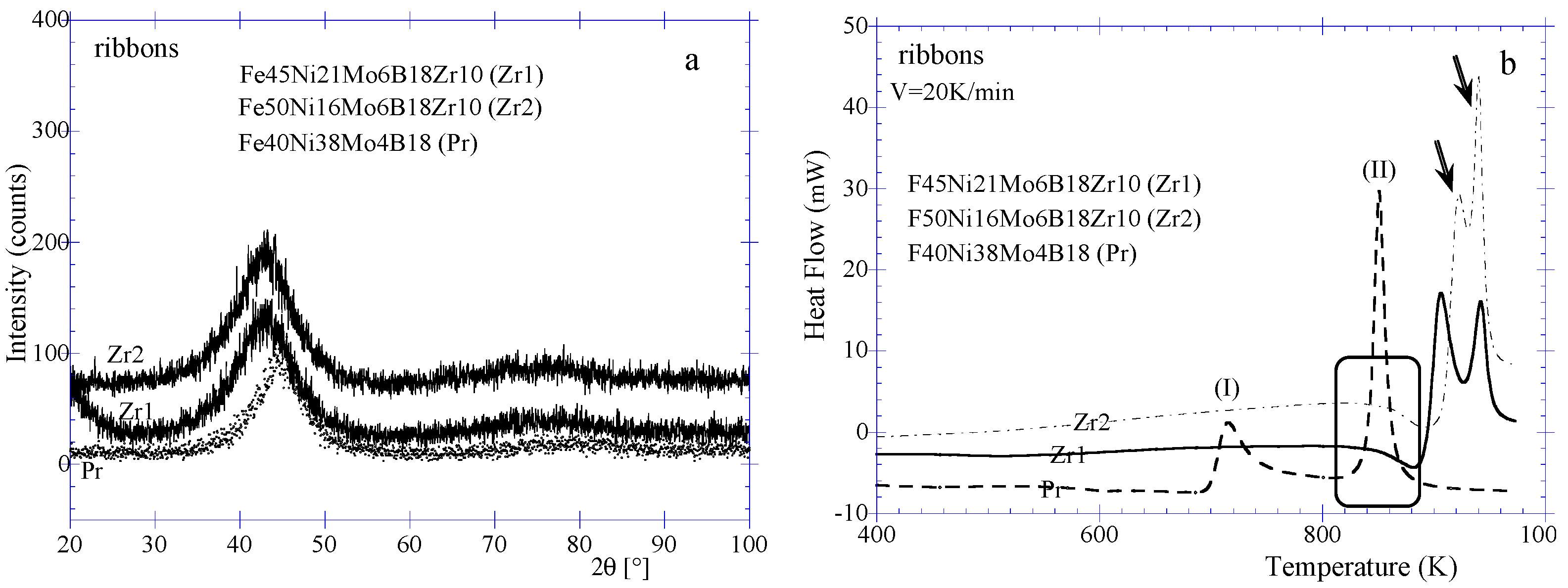
2.3. Characteristics of Fe45Ni21Mo6B18Zr10 (Zr1) and Fe50Ni16Mo6B18Zr10 (Zr2) Amorphous Ribbons
XRD diffraction patterns of Fe
45Ni
21Mo
6B
18Zr
10 (Zr1) and Fe
50Ni
16Mo
6B
18Zr
10 (Zr2) amorphous ribbons are reported in
Figure 4a along with that of Fe
40Ni
38Mo
4B
18 (Pr) ribbon. It is clearly shown that the position of the amorphous halo is shifted towards lower Bragg angle demonstrating the structural contribution of Zr atoms in the alloys. The position of the halo has a wave vector
Kp = 29.85 nm
−1,
Kp = 4πsinθ/λ with λ , X-rays wavelength; θ, the Bragg angle. This corresponds to the most probable interplanar spacing of about 0.210 nm compared to that of 0.203 nm for Pr. Choosing an interval distance around the peak position as for instance a range of 41–45 (2θ) for Zr1 and Zr2 ribbons, corresponding to the interplanar spacings of about 0.219–0.201 nm. Similarly, interplanar spacings of about 0.205–0.201 nm are obtained for Pr for a range of Bragg angle of 44–45 (2θ). These distances can be associated to presumable metastable or/and stable crystalline phases occurring during crystallization of these ribbons, for instance, Feα, c-Fe
2Zr and c-Fe
xNi
23 − x(Mo)B
6. This suggestion fuels the belief that the halo is not representative of the distance between individual atoms but rather group of atoms of a given family of plane, at least at a scale length of about 0.5–1 nm. Thus for a given atom, for instance Fe, the alloying element would be inserted in dense (0,1,1), and reduces its length by fragmentation in stair-like or zigzag.
The thermal behavior reported in
Figure 4b confirmed the amorphous nature of the ribbons. Pr does not exhibit a glass transition on the DSC curve after the structural relaxation. The two peaks (I) and (II) correspond respectively to the first and second steps of crystallization. The Zr content alloys clearly show endothermic trend (see rectangle on
Figure 4b) of classical glass transition stage. The glass transition temperatures are about respectively 813 K and 805 K for Zr1 and Zr2 while the onset of the crystallization temperatures are about 879 K and 893 K giving a ∆
Tx of 66 K and 88 K (
Table 1). This latter value is used to select Zr2 as best candidate for BMG processing since no difference is found between the half width values (θ) of the X-rays diffraction haloes of the two alloys.
Figure 4.
(a) XRD patterns of Fe45Ni21Mo4B18Zr10 (Zr1), Fe50Ni16Mo4B18Zr10 (Zr2) and Fe40Ni38Mo4B18 (Pr) ribbons. (b) DSC curves of Fe45Ni21Mo4B18Zr10, Fe50Ni16Mo4B18Zr10 and Fe40Ni38Mo4B18 ribbons.
Table 1.
Characteristic thermal parameters of processed FemNinMo6B18Zr10 amorphous with m = 45, 50, 66; n = 21, 16, 0; in: ribbon (R), wedge ingot (W), strip (S).
| Alloys composition (at %) | Tg (K) | Tx (K) | ∆Tx (K) |
|---|
| Fe45Ni21Mo6B18Zr10 (R) | 813 | 879 | 66 |
| Fe50Ni16Mo6B18Zr10 (R, W, S) | (805, 842, 834) | (893, 898, 895) | (88, 53, 64) |
| Fe66Mo6B18Zr10 (S) | 853 | 932 | 79 |
We can conclude that the segregation occurring in the multi-eutectic glass-forming alloy does not impede the amorphous ribbon formation. The homogeneity of the melt is quite maintained in terms of the presence of all probable phases. The shift of the X-rays haloes to lower Bragg angle and its broadening can be attributed to the occurrence of a new probable chemical phase involving Zr atoms.
2.4. Microstructures of Wedged and Cylindrical Ingots of Fe50Ni16Mo6B18Zr10 (Zr2) Alloy: Needles and Lamella
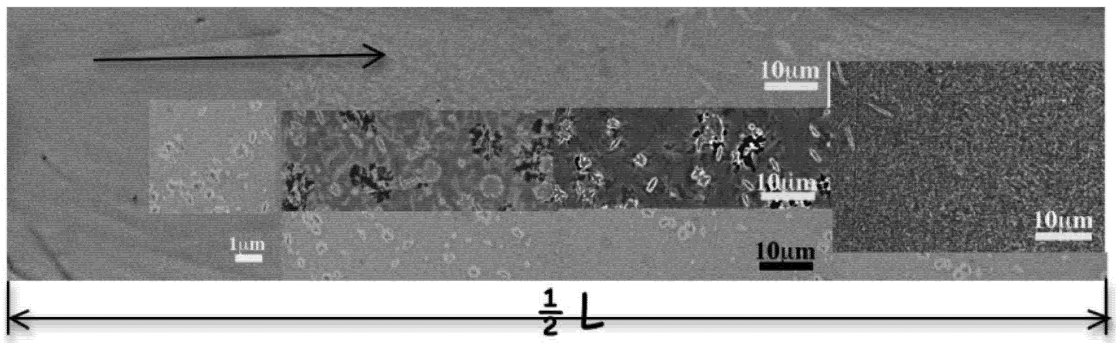
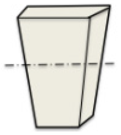
The wedged ingot (W) obtained from Zr2 is not fully amorphous. The microstructure of the cross section at about half height of the ingot (
Figure 17) is presented in
Figure 5 that represents the half section length (1/2 L). On the micrograph, the black arrow indicates the inward evolution of the microstructure. Only the peripheral area is amorphous over about 0.6 mm. At this distance, from the left side, annular-type grains are observed with variable size from 200–300 nm, probably less. This morphology reaches a size of about 2 μm close to the center where it reduces into a dot or into a plain disk with a diameter less than 100 nm. From the top, very thin needles are observed that grow inward where they mix with the annular grains. The needles reach the length of about 4 μm. Additional lenticular grains of about 2 μm length that sometimes cross in four-axes dendrites-like are observed. It must be noted that this microstructure is slightly different at other heights of the ingot and exhibits stream paths like in
Figure 2. Additional microstructures of this ingot are presented in supplementary materials (SuMat) (see Figures S1 and S2). However, the morphologies observed are identical. Contrarily to other studies [
11,
12], we never found classical dendrites or columnar grains at the interfaces of the amorphous areas.
Figure 5.
SEM-BEI micrographs of the cross-sectional microstructure evolution of Fe50Ni16Mo6B18Zr10 wedged ingot at about the half height area: from the border to the center: uniform amorphous pattern, annular, lenticular grains and needles.
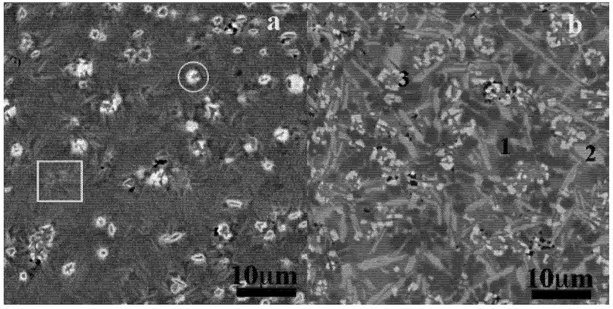
The same microstructural behavior is obtained for 8 mm diameter ingot (C8). The peripheral areas show the fine acicular microstructure with annular (white circle) and lenticular grains with a smaller size (
Figure 6a). In the center, these peculiar morphologies are thicker and their chemical compositions become more visible owing to the contrasted patterns mainly: white, and three variations of grey. They were associated to Fe-B (dark grey) (1), Fe-rich (grey), Fe-Zr (light grey) (2) and Mo-rich (white) (3) compounds. Following their locations within the ingots their compositions are variable like: 17%–80% Fe, 6%–16% Ni, 0.5%–46% Mo, 4%–54% Zr. The white phases are complex with modulation of Mo proportions with the three others metallic atoms as follows: (Fe-Mo)-rich in the C8 and W with respectively 46% Mo, 43% Fe and 22% Mo 49% Fe, 15% Zr, 14% Ni; (Fe-Ni)-rich in P with 63% Fe, 23% Ni, Mo and Zr at about 7%. Both composition and morphology indicate decreased atomic mixing and probably prominent atomic diffusion towards the center of the ingot, which can be related to the decrease of the cooling rate. The XRD patterns of one of the cross section of the W are presented in
Figure 7. All the peaks are broader and are attributed to Feα, orthorhombic (o) and tetragonal (t) Fe
3B, c-Fe
2Zr, c-BMo and potential crystalline c-[Fe, Ni], c-Fe
xNi
23 − xB
6, c-Fe
2Mo
3 phases. The multiplicity of phases can be attributed to the freedom of the atoms in the liquid to form either stoichiometric or non-stoichiometric groups, which will be present in the solid as stable or/and metastable crystalline phases. The groups of compounds formed by Fe, Mo, Zr are revealed on the EDS maps.
Figure 6.
SEM-BEI micrographs of 8 mm diameter Fe50Ni16Mo6B18Zr10 ingot processed by injection casting. (a) Fine acicular structure of the skin area; (b) Coarse acicular structure in the central area.
Figure 7.
XRD patterns of Fe50Ni16B18Mo6Zr10 (Zr2) wedged ingot selected cross section.
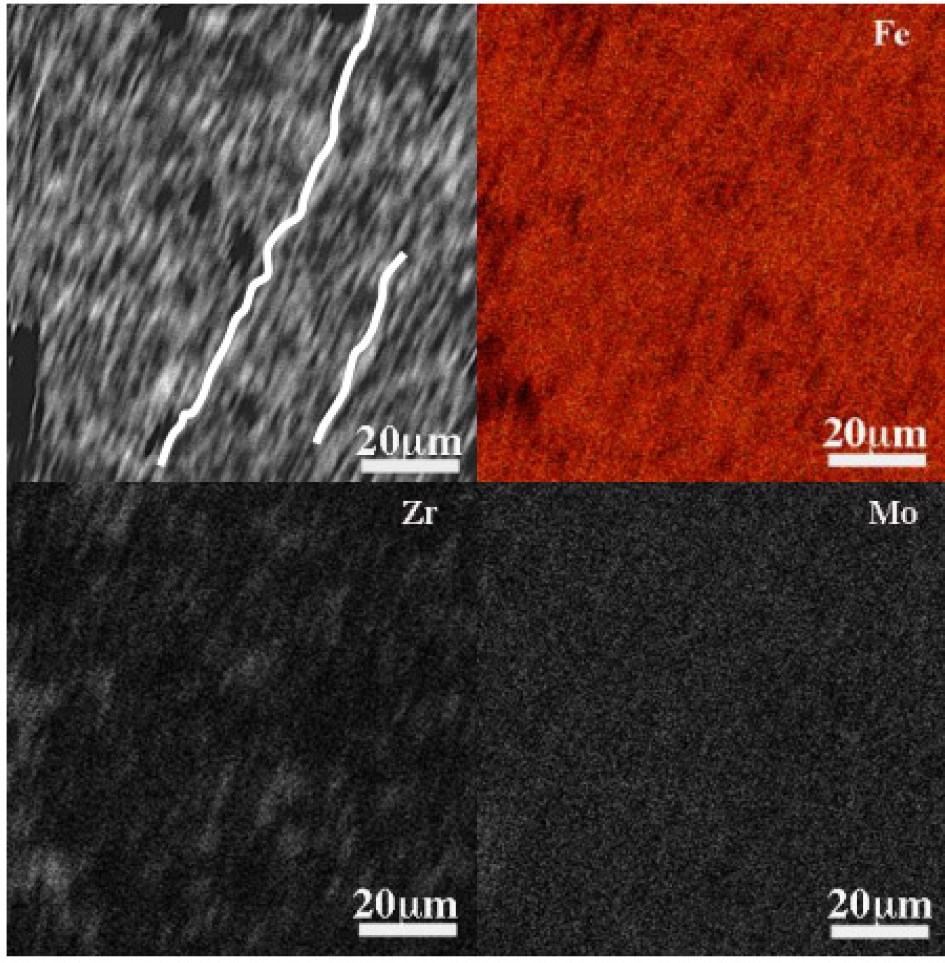
Figure 8 reports the distribution of these atoms in the microstructure of a 10 mm ingot (C10) taken close to the skin area. The SEM-BEI image associated to the chemical maps depicts distorted, twisted lamella. The lines on the image are for guiding eyes. The Fe-rich and Zr-rich portions localizations appear clearly on the maps. There are undoubtedly phases in separation, confirmed by EDS-maps from other part of the sample (see also Figure S3) that are less discernable in the amorphous phase (see Figure S4). The wavelength of the lamella, measured -ridge to ridge- is about 1–3 μm and the visible length is about 14–20 μm. Comparing the microstructures of the ingots, it is suggested that one morphology occurs during the solidification of glass-forming Zr2 melt: a lamellae. The needles are the product of the lamella’s deformation, twisting, division and fragmentation. The annular and lenticular grains are the cross sections of the needles respectively following their width and length. The annular grain is the cut following a plane with variable tilt directions on a bunch of meeting needles. See the white square in
Figure 6a as a proof of the above description of the annular grain. This acicular structure is already observed in the Zr-Cu based glass-forming alloys [
13] and the stacking of lamella is well known in the crystallization of polymers materials as spherulites [
14]. It can be assert that the spherulites in crystallized iron-based amorphous alloys have similar features [
15]. The twisting of the lamellae in this case can be attributed to surface corrugation with predominantly irregular wavelengths corresponding to the measured distances of about 1–3 μm. Corrugations have been observed on fracture surfaces of some BMGs [
16,
17,
18] with wavelength of about 80 nm that are interpreted as energy dissipating mechanism during the fracture. We can assert that the same phenomenon occurs during the solidification of melt, the excess thermal energy would be evacuated via interfaces of strained lamella. Transversal interfaces as banding of the lamella are also observed on some micrographs (not shown) taken along the skin area of the ingot where the cooling rate is higher. To our knowledge it is the first time that lamella corrugations are reported in glass forming alloy microstructure.
The microstructures of the three ingots cast with different cooling rate exhibit a unique morphology, lamellae or needle. This indicates that the Fe50Ni16Mo6B18Zr10 glass-forming alloy’s solidification mechanism is unique suggesting that the glass structure also will be built by lamella.
Figure 8.
SEM-BEI image and SEM-EDS maps of Fe, Zr and Mo atoms in the 10 mm diameter Fe50Ni16Mo6B18Zr10 ingot quenched in cold water.
2.5. Structure and Thermal Behaviors of Fe50Ni16Mo6B18Zr10 (Zr2) and Fe66Mo6B18Zr10 (Zr3) BMG Strips: Wrinkled Surfaces
Figure 9a reports XRD patterns of the Fe
66Mo
6B
18Zr
10 (Zr3) BMG strip. Peaks of crystalline phase attributed to Feα are observed over the amorphous characteristic halo. DSC curve of Zr3 in
Figure 9 shows glass transition at about 853 K and onset crystalline peak at about 932 K (
Table 1). Despite, the crystalline peaks, the material is basically amorphous, in agreement with the observed microstructure in
Figure 5. The peripheral area of W indicates that the composition with 10% can form at least a bulk of about 1–1.5 mm thickness. The strip has a thickness of about 0.55 mm. The occurrence of the crystalline peaks may be attributed to casting procedure owing to the melt injection that generates several melt streams and filets. These effects are observed on the surface of the as-cast materials (see Figures S5 and S6). Comparison of Zr3 to Zr2 specifies the incidence of Ni alloying atoms on the GFA of the alloys. The reduction of Ni and its final suppression in the alloy’s composition are likely favorable to GFA as is exemplified in the DSC curves (
Figure 9b). The Zr3 alloy shows more thermal stability as the characteristic parameters are shifted toward higher temperatures. Although, Zr2 shows also good apparent GFA, it yields poor strip and during one of the processing, after some BMG pastilles, a part of the melt went out leaving a residual solid in the crucible. The structural effect of the Ni in the alloy is not well understood. It cannot assert whether this incidence is on atomic groups formation that is on the crystalline phases formation by association with others alloying atoms, for instance Zr and B or on the acicular morphology. Investigations are in progress to clarify this observation. In contrary, Zr3 gives good strip; 200 mm long, 25 mm and 0.55 mm thick. To locate the crystalline phases on the surface of the strip, SEM observations were performed.
Figure 9.
(a) XRD patterns of Fe50Ni16Mo6B18Zr10 (Zr2) strip; (b) DSC curves of Fe50Ni16Mo6B18Zr10 (Zr2) and Fe66Mo6B18Zr10(Zr3) strips with Fe40Ni38Mo4B18 (Pr) ribbon.
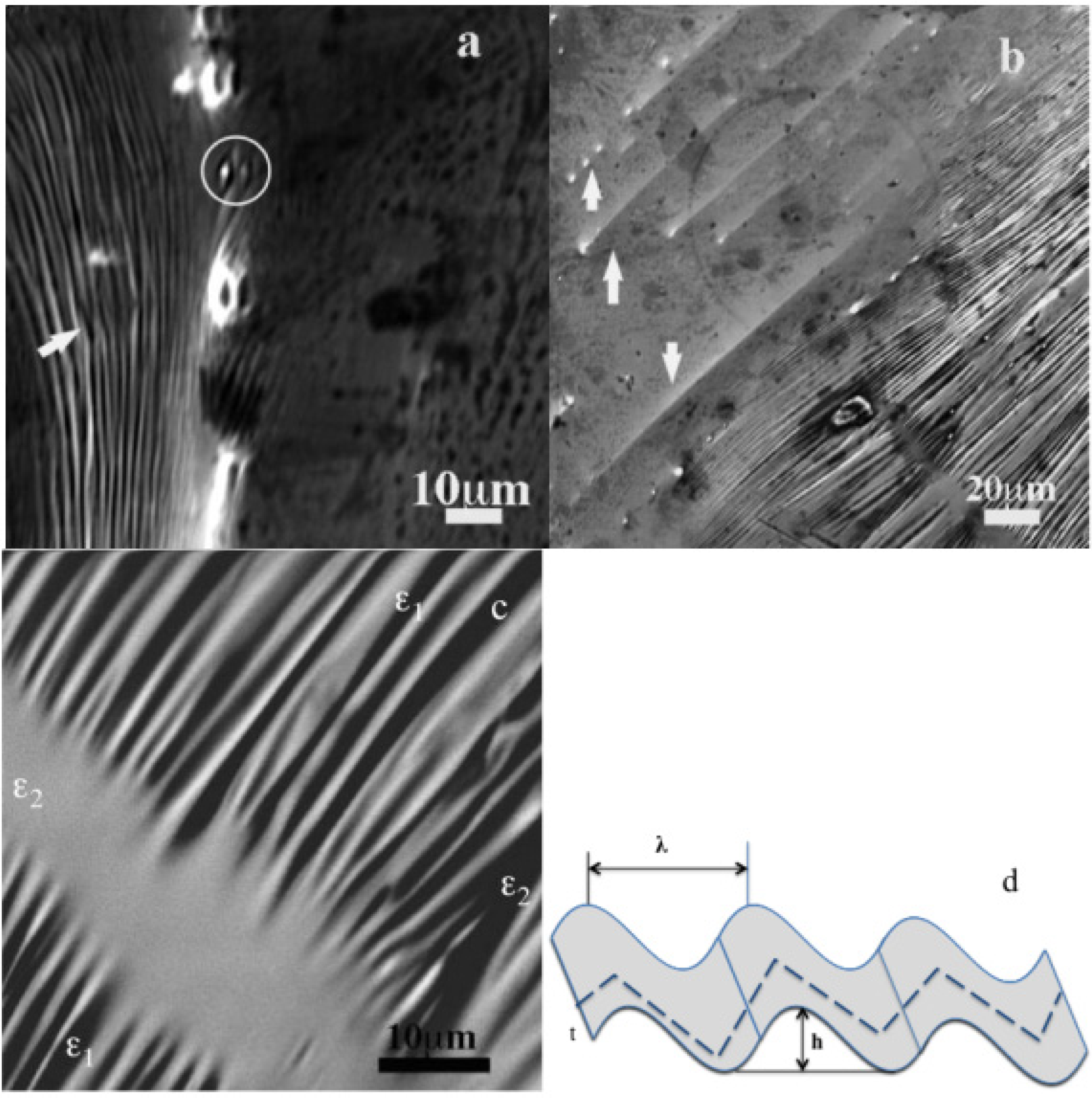
Figure 10.
(a) SEM-SEI micrograph of wrinkles on as cast surface of Fe66Mo6B18Zr10 (Zr3) BMG strip: note the polyhedral-like grains; (b) SEM-BEI micrograph of as cast surface of Fe66Mo6B18Zr10 (Zr3) BMG strip; needles and wrinkles; (c) SEM-BEI image of wrinkles presumably under two strain directions: ε1 and ε2; (d) Sketch showing the wrinkling and the serration (discontinuous line) on the surface of the BMG; λ wrinkle wavelength, h wrinkle amplitude, t surface thickness.
The microstructure of the Zr3 surface is reported in
Figure 10. While neither contrast nor pattern can help find the crystalline phase, wrinkles (white arrow) and peculiar four-axes concave (white circle) and convex polyhedra-like are observed. The convex one is likely the inverse of the concave one, forms by the changing direction of the wrinkles. The wavelengths of the wrinkles are about 1–3 μm. In general, the wrinkles have irregular wavelengths, but at least two identical wavelengths are found, and some areas can have identical wavelength over 10 waves. The wrinkles exhibit corrugation in the transverse direction appearing as reduction of the wrinkle thickness. The length—groove to groove—of these ripples gives of about 5–15 μm. It is the first time observations of such wrinkles are indicated for metallic glass. However, back observations of the surfaces of our other Fe-based and Zr-Cu based strips and micrographs from the literature revealed wrinkles on the materials [
8]. On other parts of the surface, lines and dots appeared in apparent relation with the underneath wrinkles (
Figure 10b, arrowed) as being the merging and the reorganization of wrinkles into needles (see sketch on
Figure 10d).
Wrinkles are commonly observed in natural materials [
19,
20], on stretched membranes and thin films [
21,
22,
23,
24,
25,
26,
27,
28], in synthetic materials [
28,
29], on surface growth of oxides [
30] and on the solidified surface of liquid [
31]. They typically account for applied strains or stress relaxations in the thin materials. Following the submitted in plane strains directions the wrinkles change from single surface corrugations to a complex wrinkled patterns. The wrinkle wavelength λ is function of the dimensions and the elastic constants of the membrane (
Figure 10d). It can be expressed in function of the Young modulus of the film and the substrate: λ ~ (Lt)
1/2 ε
−1/4, with, L and t respectively the length after stretching and the thickness of the membrane and ε the strain, ε = L − Lo/Lo, Lo initial length [
23] for strained membrane or as λ/t = 2πK
1/3 [
24], with
K =
Es/4
Em(1 − πν
s2);
Es and
Em, respectively Young modulus of the substrate and the membrane, ν
s the Poisson ratio of the substrate for strain relaxation of the membrane. The wrinkles on the surface of the BMG can be then undoubtedly interpreted as the formation of strained layered thin film as part of the aggregates bulk. The wrinkles are the way the incipient solidified melt relaxes and maintains its dynamic stability. Conservative behavior can also be derived from the convex (depressed) and concave (inflated) (see circle in
Figure 10a) polyhedral-like patterns. Their apparition seems to fit equilibrium constraints. Lines and dots (
Figure 10b) are likely, respectively, the side and the end (top) view of a needle. It is likely that the wrinkles are inherent to the casting of metallic glass; melt injection or suction that imposes variable flow rates to the melt inducing strains (stresses). The features of the wrinkles in
Figure 10a can be associated with viscous-like deformation (smooth apex) [
32], as opposed to shear deformation (acute apex) likely related to the needles in upper part of
Figure 10b. The description in
Figure 10d is also in agreement with the variety of wrinkle patterns like, strip, labyrinth and herringbone. The latter is the evolution of the labyrinth when the strains become anisotropic [
33]. There is an association with wrinkle-needle as isotropy-anisotropy that can be hierarchically observed at nanoscale as a liquid-solid demonstration. Since the wrinkled film wavelength’s is larger than its thickness, we can conclude that the wrinkled surfaces on the BMG surface are thin layers. Taking a mean thickness of about 2 mm of the 15 mm wrinkles gives λ ≈ 5t that yields Ef/Es ≈ 1. In fact, the calculation for more wrinkles indicates Ef/Es values between 1 and 2, which indicate that the layers have close mechanical properties.
In the case of Zr3, wrinkles are also observed within the bulk. These inner wrinkles are probably responsible of the weak response of the material to applied stresses. This strip breaks when it is tightened in a vice.
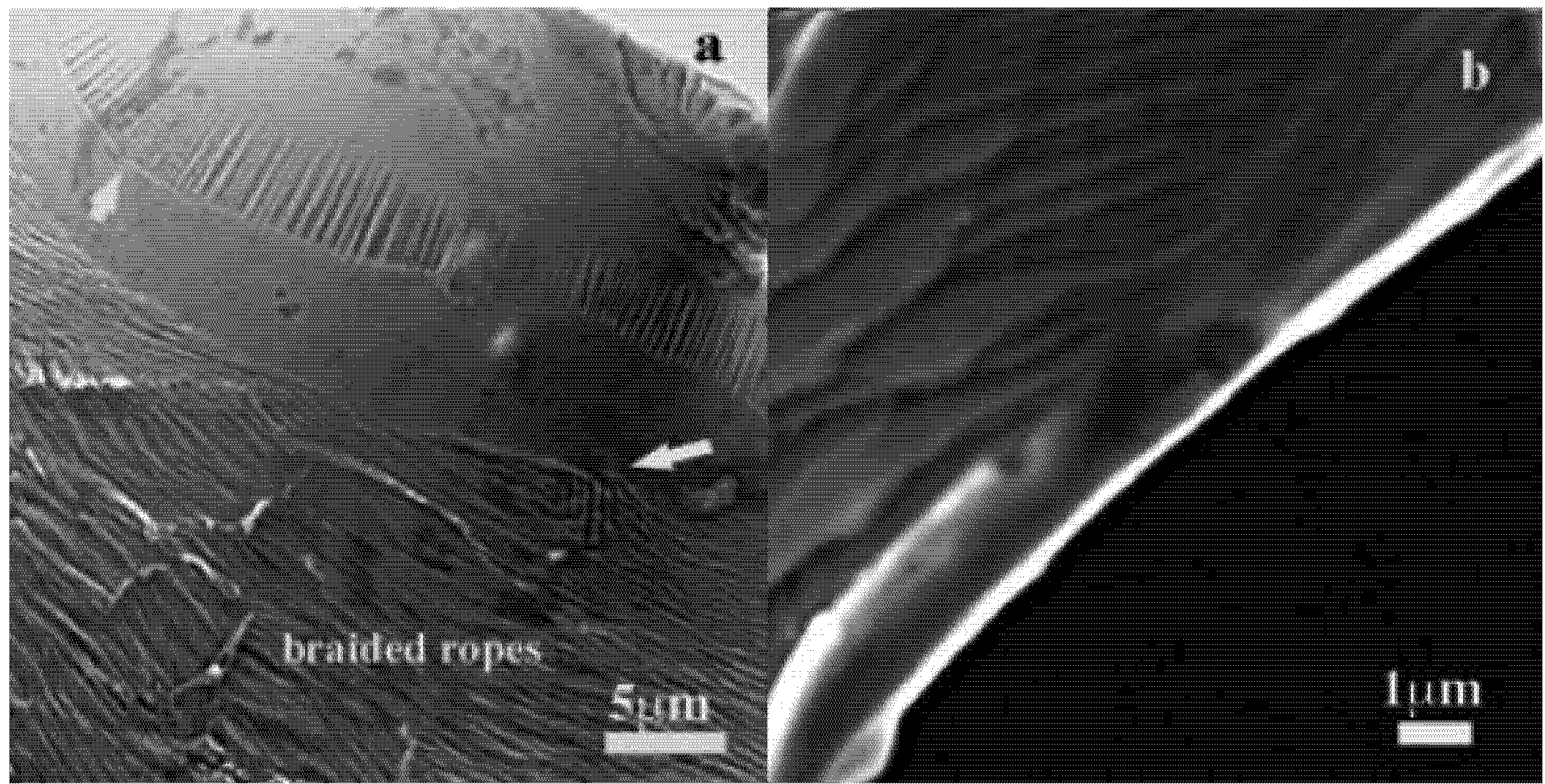
Figure 11 shows the microstructure of the rupture surfaces of a broken strip. Wrinkles with λ of about 13–30 μm and amplitudes of about 2–4 μm are observed covered at each end by smooth surfaces. Another wrinkles as braided ropes or nano twisted wires having λ of about 150–300 nm, 10 times smaller of the first ones are lying beneath the smooth surface. It is likely the result of the merging of the two families of wrinkles as can be observed in the arrowed areas. Bandings observed on these latter are undoubtedly related to the second wrinkling direction. The microstructure in
Figure 11a can be qualified as strain induced pattern like that obtained after mechanical test except that in this case the same pattern is observed on the surface of the strip. This similarity of the wrinkled patterns is a proof of the underling identical mechanical mechanism.
Figure 11b shows another area where shear bands are observed that creates cells pattern. The smallest are constitutive of lamella similar to wrinkles. EDS maps for this area are provided (see Figure S7). Moreover, large wrinkles of about 30 μm are also observed as corrugation of the inner bulk surface. These described microstructure characteristic within the bulk of the strip suggests poor strain relieves between the wrinkled interfaces and thus mechanical effects on surface atoms, atomic layers or row of atoms rather than on individual atoms.
Figure 11.
(a) SEM-SEI micrograph of wrinkles on a rupture surface of Fe66Mo6B18Zr10 (Zr3) BMG strip: note the two directional wrinkles (arrowed); (b) SEM-BEI micrograph of a rupture surface of Fe66Mo6B18Zr10 (Zr3) BMG strip: shear bands and cells.
2.6. Microstructure of the Surface of the Residual Solid of Fe50Ni16Mo6B18Zr10 (Zr2)
As was mentioned in the previous section, residual solid retained in the crucible during one strip processing of Fe
50Ni
16Mo
6B
18Zr
10 after some pastilles and distorted and porous strip. The three materials have different structure but their chemical compositions are close to the master melt. The residual material, appearing as decanted [
34] solid surface microstructure is presented in
Figure 12. The first observation is that the lines or lamella are similar to that observed in
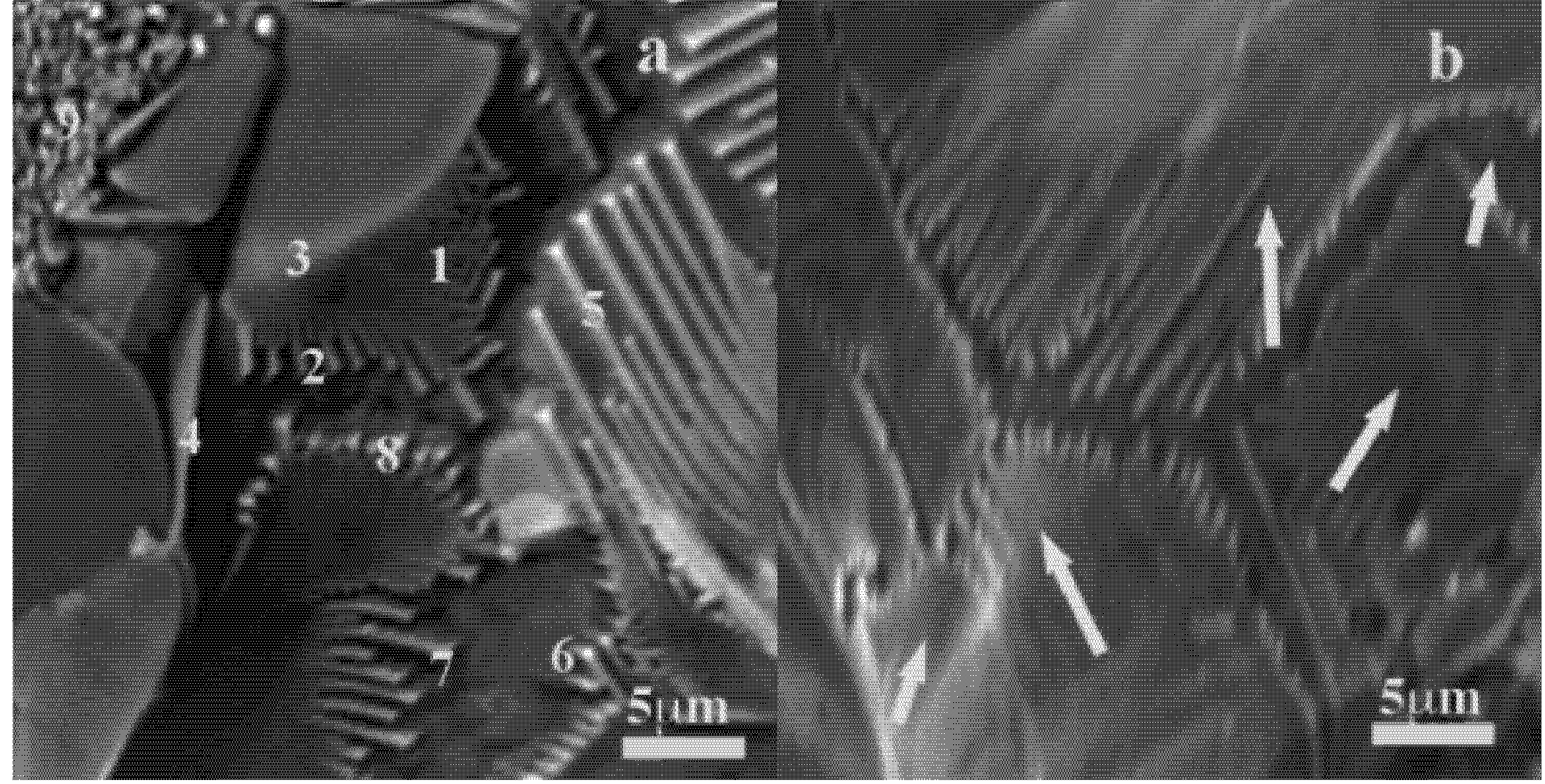
Figure 10a. All the lines are branched, with various directions, that allow them to: form a smooth surface (1), to keep contact with the bulk (2), to adapt to external stresses (3) with its various features (4-7) and to curve (8); the (4) is the side of a flake that forms a flower-like solid with three other flakes around; the (9) is a gathering of the needles’ tips; the (6) shows a branching, which is in fact an individual line meeting another one.
Figure 12.
(a,b) SEM-SEI micrographs of the surface of the residual solid in the crucible after injection of Fe45Ni21Mo6B18Zr10 alloy.
The flakes are formed by the needles, which in turn likely construct a spherulite.
Figure 12b completes the information about the needles and how they are organized to form a surface adapted to external and internal constraints. In this figure, the arrows indicate the different visible lines directions than can be considered as random. Hexagonal-like grains pattern and grains boundaries are also observed. These latter indicates the change of underneath line direction, this tied to the bulk. Some ripples on the surface suggest wrinkles.
The line observations and their organizations to form surface specify that the needles formation is intrinsic to the glass forming melt. The “decanted” surface allows better observations of the microstructural crystalline phases’ morphologies, for instance the branched needles commonly termed as dendrites.
Figure 11,
Figure 13 and Figure S8 suggest strongly that the wrinkling is not only superficial but also a bulk mechanism, which may be attributed to the morphology of melt filets or filaments.
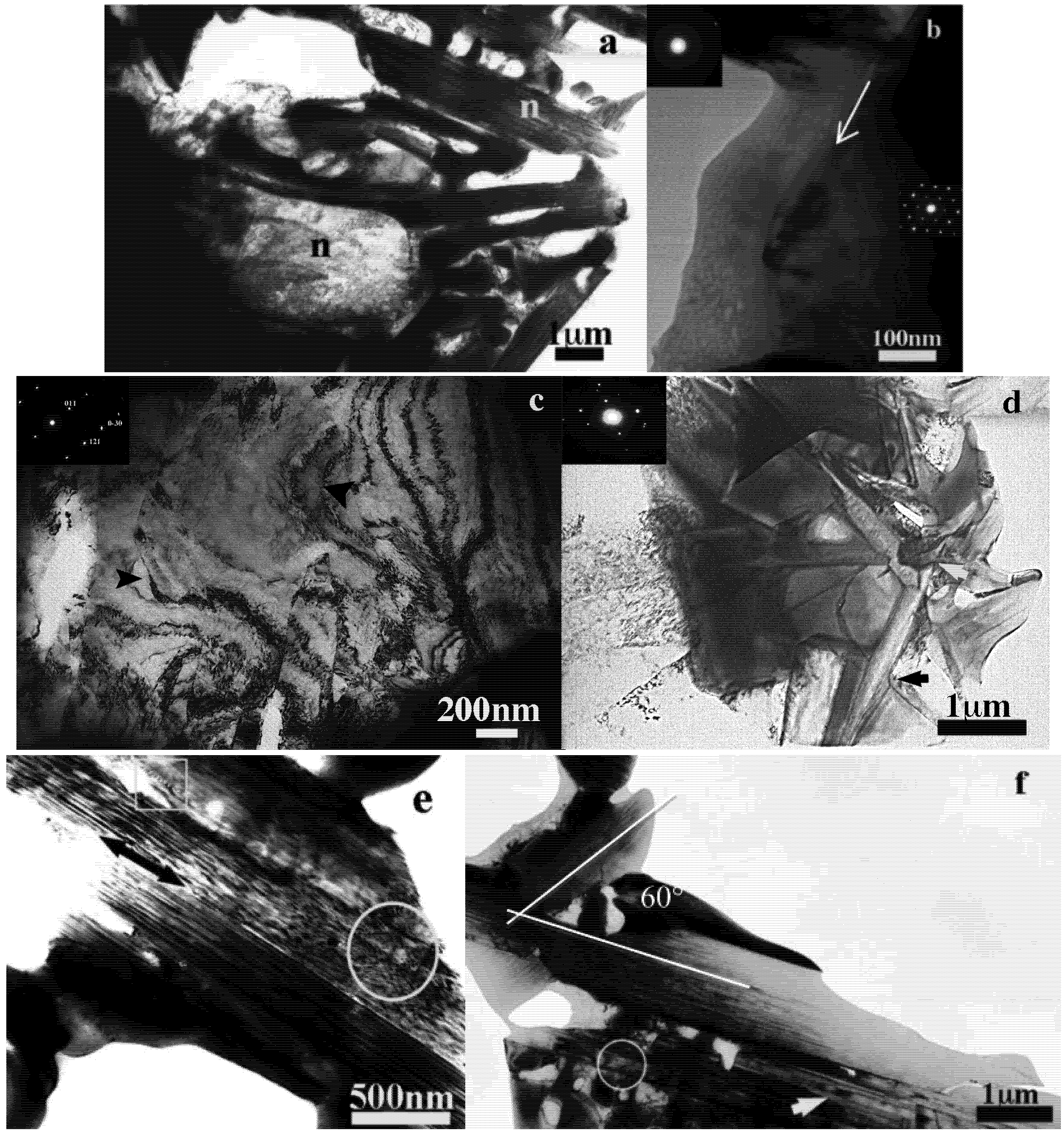
Figure 13 reports the transmission electron microscope bright field images (TEM-BF) of the 8 mm diameter (C8) injected ingot. Various kind of needles and details of their constitution are observed in
Figure 13a,c–f.
Figure 13b presents an amorphous pocket between some needles. The amorphous pattern exhibits a chain of a lozenge-type morphology emerging from needles. This peculiarity is clearly visible on the left of the arrow that indicates the interface between the amorphous zone and crystalline phase oriented in [111] zone axis. This evidences a close relationship between amorphous phase and needle or in other words, the needles are likely the growth morphology of the structural basic unit involved in the amorphous phase.
Figure 13c (arrowed) shows the association of needles side by side and head by head, the larger needles having the thickness of about 300 μm. For instance, that in the bottom of the image is constituted by the merging of smaller needles with variable thicknesses, the measured thinnest is about 20 nm thick (see Figure S8 for more observations). The bending black contrasts on the image reveal curved needles like bellows observed in
Figure 12a (8). Selected area electron diffraction (SAED) patterns in this area indicate the presence of Feα and o-Fe
3B (SAED inset
Figure 13c) that suggested complex lamellar eutectic structure or acicular eutectic. The symmetrical needle tip is arrow-headed with an angle of about 60° while the asymmetrical angle scaled to 70° and 80°.
Figure 13d shows the second type of needles less thick of about 100 nm under bulk view.
Figure 13.
TEM-BF micrographs of Fe50Ni16Mo6B18Zr10 (C8) thin specimen from the 8 mm diameter ingot: (a) Image of acicular microstructure; (b) Image of an amorphous pocket; (c) Image of acicular microstructure with bending contrast and dislocations; (d) Image of needles network. (e,f) Image of row of lamellae within a needle and needles crossing angle.
Needles in agreement with observations in
Figure 6 cover all the area. Variable tilt plane angle interception of this needles’ network area form the annular and the lenticular grains observed in
Figure 4,
Figure 5,
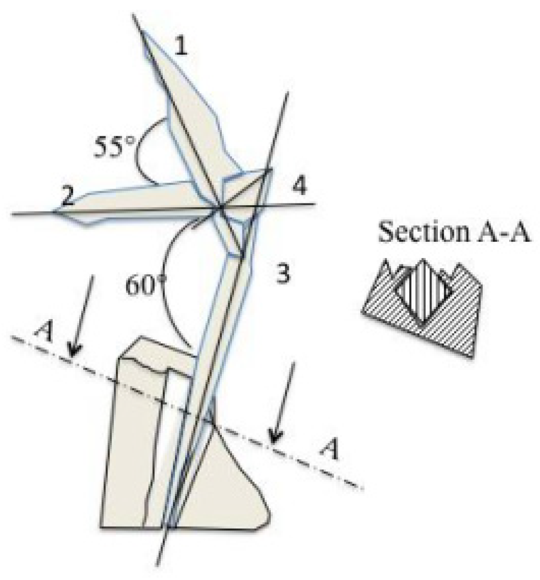
Figure 6. Black arrow indicates how the needles assemble like a mechanical shaft and bore. A sketch of this image is shown in
Figure 14. Needle (2) goes through (1) that enters (3) and (4) is directed out of the plane of the image. This observation demonstrates a liquid-like behavior, meaning the needles owned their morphologies before solidification. Otherwise, they will not go through but stop at the intersection to form twins. These latter can be observed within the needle (1), which is likely formed by a row of quadratic (see cross section A-A in
Figure 14) plates. Moreover, needles (1) and (2) are twisted in
Figure 13d. Transversal lamella (see the circle and the square in
Figure 13e) is probably the initial state of the quadratic plates. The double arrow in this image shows row of lamella building the needle similar to the one in
Figure 8. The lamellae thickness is about 10–20 nm compared to 2 μm in
Figure 8. It is 10 times smaller indicating hierarchical structure. The shaft’s morphology and the chain–like organization reveal motion behavior that is consistent with a flow. TEM images show also the overlapping of the needles and the lamellae in
Figure 13f (white circle) and the grooves on it (arrow). The underneath eutectic structure can be observed through the lamellae which is about 50 nm wide. Upper needle constitution is also highlighted with the crossing angle similar to that in the
Figure 13d. These needles are c-Fe
2Zr and c-Fe
3Zr phases with cell parameters respectively of
a = 0.702 nm and
a =1.175 nm. The third type of needle is shown in
Figure 12e, which is likely a t-B
2Mo crystalline phase with cell parameters
a = 0.311nm and
c = 1.695 nm. The angle of about 60° between needles in
Figure 13f, and c with
Figure 14 corresponds to an angle between two {0,1,1} and that of 55° between {1,1,0} and {1,1,2} for instance. These correspondences will be checked exactly in further studies.
Figure 14.
Sketch representing the needles network in
Figure 13d.
2.7. First Steps of a Microstructural Model of the Amorphous Structure (MMAS)
As observed on the SEM micrographs of C8, the acicular microstructure is confirmed by TEM observations and needles details constitution and crystalline phases characterized. The location of the amorphous pocket within needles indicates a solidification rate variation within the liquid during the quenching. The amorphous pattern suggests a hierarchical phenomenon involving thin strained lamella probably about 2–3 atomic layers due to the flow mechanism, the collective motions of atoms. These rippled atomic layers merge to form the amorphous cells that grows into needles or larger lamella following the solidification rate. This latter governs the amorphous process because it is related to the melt flow established by the melt viscosity. Solidification is achieved when the melt flow is close to zero leaving ripples and serration within the material. It is likely that lamella motions generate the flow. Thus, the glass-forming solid microstructure can be imaged as a “mille feuilles”, a French cake made up of layered puff pastry. The amorphous material can be compared to a solid composed by broken “mille feuilles”.
It is a new look into the amorphous structure that introduces the effective mechanical contributions to the formation of the amorphous solid. For instance, the random network of the needles is the result of the wrinkling of the lamella under random directed strains resembling to the amorphous pattern in
Figure 13b similar to that shown in white circle in
Figure 13e at nanoscale and in
Figure 9 at microscale.
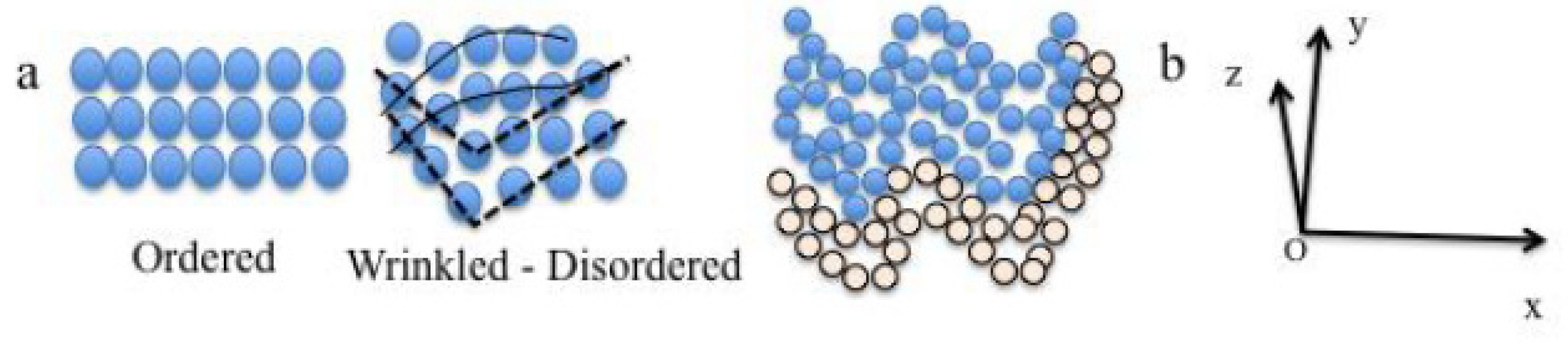
The microstructural model of amorphous structure (MMAS) states that: (i) the mechanical effects on atomic scale are on chain of atoms and atomic layer than on single atoms resulting in wrinkled atomic layers (
mesowrinkles); (ii) the mixing and merging network of the wrinkled atomic layers or lamella form the cells network (
nanowrinkles); (iii) the association and organization of cells (c) form wrinkled lamella (
microwrinkles) that are constitutive of BMG material. Thus, it is necessary to generated enough stress relieves on the wrinkles surface during casting to obtain larger diameter and avoid brittleness. The mechanical effect on atomic layer can be observed on the sketch in
Figure 15a. A wrinkled atomic layer can be easily constructed within the classical representation of disordered atomic organization. The wrinkling of the atomic layers can follow the description in
Figure 15b where a three-axis system can be connected to the layers; the z-axis represents the thickness t of the layers.
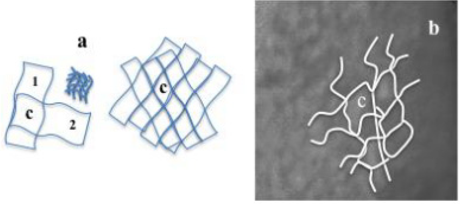
Figure 16 presents the mechanism of the formation of the lozenge-type cell—in fact a polyhedron—by the crossing and the merging of two wrinkles, the multiple wrinkles network (a), and its representation on the amorphous pattern of the
Figure 13b. Since the wrinkled surfaces are formed by lamella, the cell (c) is a bunch of wrinkled atomic layers, its SEAD pattern would shows rings like a curved atomic sheets [
35]. The various wrinkles thickness has to be determined in order to estimate the Young modulus of the layers according to the scaling laws described by Cerda
et al. [
36] or other laws. This must be done also at atomic level on high-resolution electron transmission images. In the case of these latter, the observation of the same wrinkling patterns and associated peculiar features in optical micrographs (
Figure 13b) would undoubtedly help depict the right microstructure of amorphous phase. The SAED rings and the X-rays haloes would be correlated to the wavelengths of the wrinkles at atomic scale.
Figure 15.
(a) Sketch showing the classical representation of crystalline and amorphous atomic organizations; (b) Sketch showing the wrinkling of atomic layers under strains and the direct axis that can be linked to the wrinkled atomic layers.
Figure 16.
(
a) Sketch showing crossing of two wrinkled surfaces to create a cell (c), the constitution of the cell (c) (following
Figure 11a(1)) with lower lengthscale wrinkles and wrinkles network; (
b) Equivalent representation on the amorphous pattern in
Figure 13b.
This proposed description of the MMAS is consistent with the graphene and carbon nanotube buckling under stresses or strains [
37,
38,
39,
40]. It is also in agreement with observations of wrinkled sheets of ~65
–85 nm with central units of semi ordered atomic layer of about 3–8 nm in amorphous FeS [
29]. In other words, if the amorphous material were exfoliated to a single atomic layer, one would find a wrinkled layer. It is presumably the mechanism of the amorphous formation by mechanical alloying techniques. The wrinkling would account for single or multiple elastic strains or shears. The stacking of the wrinkled layers (mille feuilles) would form the amorphous structure with the lozenge-type cells pattern. The atomic organization of this latter will be described in further papers.

