1. Introduction
Titanium alloys are widely used for applications requiring an excellent mechanical resistance and high strength at elevated temperature. This alloy has high mechanical characteristics that allow better performance on commercial aircraft, and a significant gain compared to the commonly used Ti-6Al-4V alloy. Beyond its interesting ratio density/mechanical properties, the Ti-55531 alloy provides significant benefits for the demanding environment of aeronautics. This comes from its ability to maintain mechanical properties at high temperature, the fatigue strength and its excellent corrosion resistance [
1,
2]. Clément
et al. [
3,
4] have reported that the high level properties of titanium alloys depend on several strengthening mechanisms such as grain size, solid solution atoms, and precipitation hardening, which all can be tuned during the various forming processing steps, leading to particular microstructures.
In manufacturing production, titanium alloys are classified as hard to cut materials. The main problems encountered when machining titanium alloy are the low material removal rate and the short tool life because of the excessive wear exhibited during the chip formation process. The first findings of machining Ti-55531 alloy are manifested by low cutting speeds. This causes high cycle times and reduced tool life, and then generates an increase in manufacturing costs.
Titanium is chemically reactive and, therefore, has a tendency to weld to the cutting tool during machining leading to chipping and premature tool failure [
5,
6,
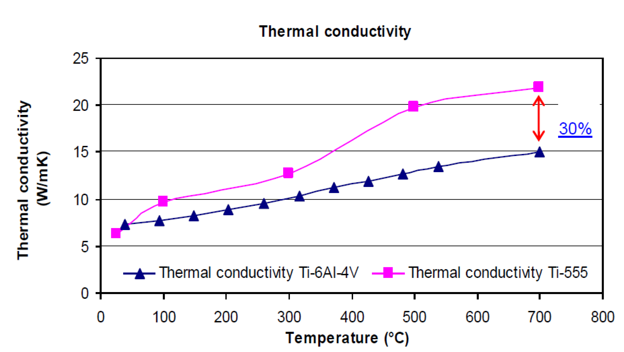
7]. In addition, its low thermal conductivity (about 15 W/m K
vs. 270 W/m K for the steel CRS1018 at 700 °C) increases the temperature at the tool/workpiece interface, which adversely affects the tool life. Additionally, the high strength maintained at elevated temperature and low modulus of elasticity (50% less than that of the steel) further impairs the machinability of these materials [
6,
7,
8,
9]. According to Ezugwu [
10], the tool wear in machining of titanium alloys is due to high stresses and high temperatures found near to the cutting edge. The same conclusions were made by Subramanian [
11].
From a microstructural point of view, elemental titanium presents an allotropic phase transformation at 880 °C between the body centered cubic (bcc) and hexagonal close packed structures stable at high and low temperatures, respectively. The two phases of titanium alloys are known as α phase and β phase respectively [
12]. Combinations of working and heat treatment alter the microstructure and change the mechanical properties of the metal. The microstructure and properties can also be affected by adding other elements to titanium. Addition of other elements to pure titanium,
i.e., alloying, can alter microstructure and properties as well. Depending on which phase is to be dominant in a particular alloy (α, β or α + β) an alloying element (or group of elements) may be added to pure titanium [
3,
4,
5]. Thus, one way of classifying alloying elements is according to whether they are α or β stabilizers. Alpha stabilizers are soluble in the α-phase and many act as solid solution strengtheners while also increasing the temperature at which the α-phase is stable. Alpha stabilizers include such elements as Al, Ga, Sn, Ge, and La. Beta stabilizing elements decrease the β transus (
i.e., the temperature at which the material transforms to 100% β-phase). As such, these elements increase the range over which the β-phase is stable. Beta stabilizers may be isomorphous or eutectoid. Isomorphous elements (such as V, Mo, Nb, Ta, and Re) are soluble in the α-phase while eutectoid elements like (Cr, Fe, Mn, Cu, Ag, Au, Ni, and Co) create a eutectoid phase.
According to Fanning [
13], Ti-55531 (TIMETAL 555) is a high-strength near-β titanium alloy that was designed for improved productivity and excellent mechanical property combinations, including deep hardenability especially in aeronautical and aerospace industries. According to the same author and to Clément
et al. in [
3,
4], this recent alloy was designed based on the older Russian alloy VT22 to primarily fulfill high-strength forging applications. A lower-strength state with improved toughness and damage tolerance is under consideration for other parts of aircraft structure [
14]. However, being of recent origin, there is a lack of information on machining of this alloy. This is despite the existence of information regarding thermomechanical processing of this family of alloys [
15], and the abundance of information available regarding machining of titanium and some of its alloys (notably Ti-6Al-4V) [
16]. In the machining field, it is well known that titanium and titanium alloys are hard-to-cut materials. This means that Ti-55531 will most likely present engineers with many technical problems to be solved in order to produce net shape components. Bouchnak recently proposed in [
12] a study on the machinability of this material and assistance techniques to enhance the machining process. However, according to the literature in the field of machining, the state of the art does not present optimal solutions or does not give the real parameters that influence the cutting forces and tool wear (cutting conditions, tool geometry, and cutting material).
In order to increase productivity and tool-life in machining of titanium alloys, it is necessary to study the chip formation process and its effect on the physical cutting parameters and the material cutting performance. The objective of this study is to understand the poor machinability of titanium alloys especially the Ti-55531 one which exhibits extreme tool wear and unstable cutting forces.
2. Experimental Section
2.1. Titanium Alloys
To analyze the machinability of the titanium alloys Ti-6Al-4V and Ti-55531, a parametric study was conducted through several orthogonal cutting tests (cutting tests). The chip formation and tool wear processes were investigated particularly in terms of cutting parameters such as cutting forces, friction coefficient and cutting temperature,. Tests were carried out on a heavy-duty lathe machine with an 11 kW motor drive, which generates a maximum torque of 1411 Nm. The spindle rotational speed ranges from 18–1800 rpm.
As mentioned above, two alloys were chosen for machining experiments. The first one was the alloy Ti-6Al-4V, considered as the reference for these tests. It is characterized with duplex structure α/(α + β), and average grain size around 10 µm (range from 5–20 µm). The second alloy studied here is the Ti-55531 with average grain size around 1µm (range from 0.5–5 µm).
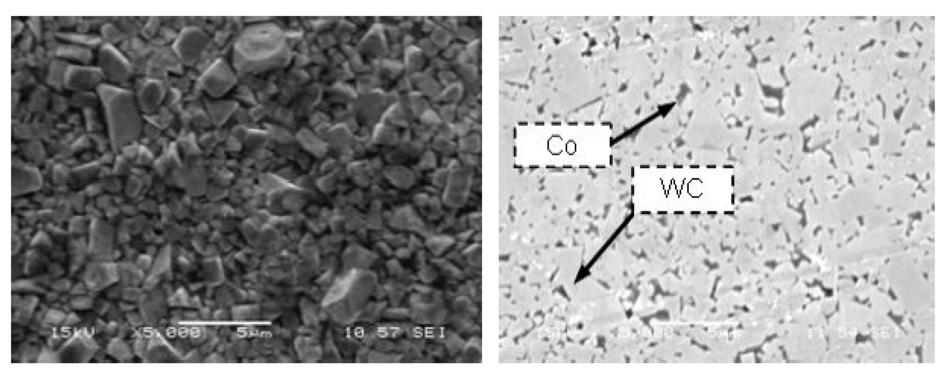
Figure 1a–d depict the microstructure of each workpiece alloy before machining. The initial microstructure of the Ti-6Al-4V alloy,
Figure 1a,b, consists of single phase α matrix. Inclusions of β grains can also be seen with average grain size of 10 µm (range of 5–20 µm). Similarly, the initial microstructure of the β alloy Ti-55531 is shown in
Figure 1c,d. The microstructure consists of single phase β matrix with average size of α grains of 5 µm (range 1–5 µm).
In this work it was found that the lamellar structure can be observed in α + β colonies (transformed β); particularly for the Ti-6Al-4V alloy.
Figure 1a shows the localization of the lamellar structure. This was previously confirmed by the work of Benedetti and Fontanari in [
17].
Figure 1.
Microstructure of the workpiece material used in the current study before machining. (a,b), α + β alloy Ti-6Al-4V; (c,d), β alloy Ti-55531.
Table 1 presents a summary of the chemical composition of both alloys. According to Bouchnak [
12], Fanning [
13] and Nouari
et al. [
18] the physical properties of the Ti-6Al-4V and Ti-55531 alloys are summarized in
Table 2.
Table 1.
Chemical composition of machined titanium.
| Chemical element | Ti-6Al-4V (wt.%) | Ti-55531 (wt.%) |
|---|
| Al | 5.5 | 5 |
| V | 3.8 | 5 |
| Fe | Max 0.8 | 0.3 |
| Mo | 0 | 5 |
| Cr | 0 | 3 |
| Nb | 0 | 0.5–1.5 |
| Zr | 0 | 0.5–1.5 |
To complete the characterization of studied titanium alloys, tests of Vickers hardness were performed on different specimens at room temperature. The micro-hardness of the Ti-6Al-4V specimen was found to be about 317HV0.2 and that measured for the Ti-55531 alloy to be about 379HV0.2. Ti-55531 is therefore 20% harder than Ti-6Al-4V. This result confirms the hard nature of the Ti-55531 microstructure, which will have a direct effect on its machinability, i.e., the level of cutting forces, tool wear, cutting temperature, etc.
Table 2.
Mechanical and thermal properties of Ti-6Al-4V and Ti-55531.
| Thermal and mechanical properties | Ti-6Al-4V | Ti-55531 |
|---|
| β transus (Tβ) (°C) | 980 | 856 |
| Density (g/cm3) | 4.43 | 4.65 |
| Tensile elastic modulus (GPa) | 110 | 112 |
| Compressive elastic modulus (GPa) | -- | 113 |
| Tensile strength (MPa) | 931 | 1236 |
| Yield strength (MPa) | 862 | 1174 |
| Elongation (%) | 14 | 6 |
| Thermal conductivity at 20 °C (W/m K) | 7.3 | 6.2 |
| Specific heat 20–100 °C (J/Kg K) | 709 | 495 |
4. Results and Discussion
The obtained results are shown depending on whether one considers lubricated or dry machining, and the use of tools with or without coating. The calculation of the friction coefficient in various cases was also performed. The effects of the tool geometry and the cutting speed on machinability are analyzed. Also an attempt has been made to examine the effect of various process parameters on the chip morphology and tool wear during machining two different titanium micro-structures: Ti-6Al-4V and Ti-55531.
The effect of the tool geometry on the machinability is presented here with results on both alloys machined with TiAlN coated tools. The analysis of these results was performed with a comparison on the machinability of the alloys according to the cutting forces, friction and the specific energy of the machining.
4.1. Cutting forces
The cutting forces affect machining quality depending on cutting conditions, tool and workpiece materials. Thus, the measurements of forces give indications on machinability of the machined material. In addition to the friction at the tool/chip interface, cutting forces depend on two main factors: area of the primary and secondary shear planes, and shear strength of the work material at these planes [
26,
27].
Figure 6 and
Figure 7 illustrate cutting forces (
Fc) and feed forces (
Fa) generated during machining titanium alloys Ti-6Al-4V and Ti-55531. The evolution of machining efforts is plotted as a function of the cutting speed
Vc and the considered tool geometry.
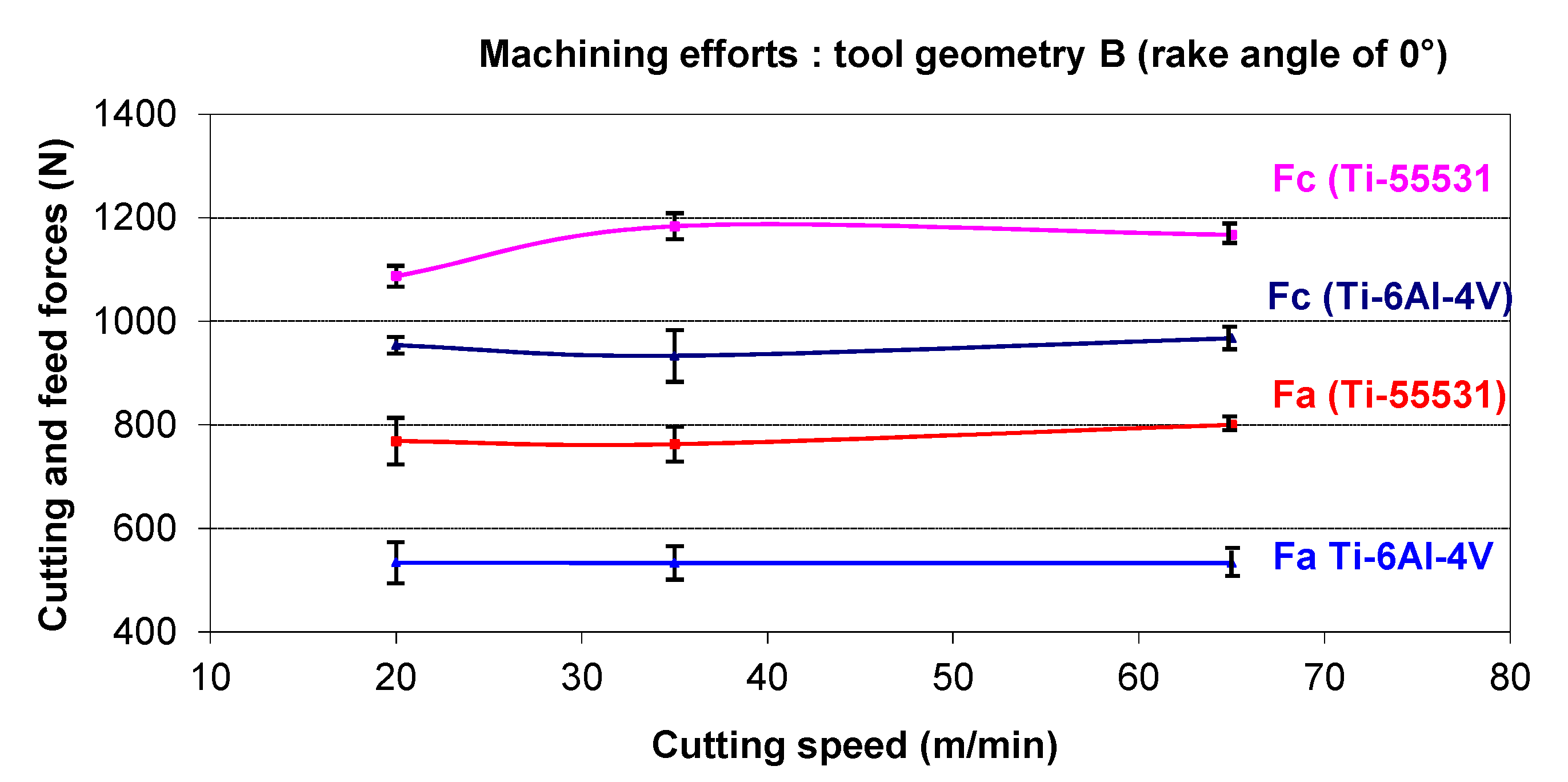
Figure 6.
Cutting forces obtained for Ti-6Al-4V and Ti-55531 with tool geometry “B”.
It can be observed from
Figure 6 and
Figure 7 that
Fc is the dominant force component. Therefore, the discussion on cutting forces is focused on the cutting force due the weak variation of feed forces. As seen in
Figure 6 and
Figure 7, the feed force remains stable for all conditions.
First of all, it can be noted from
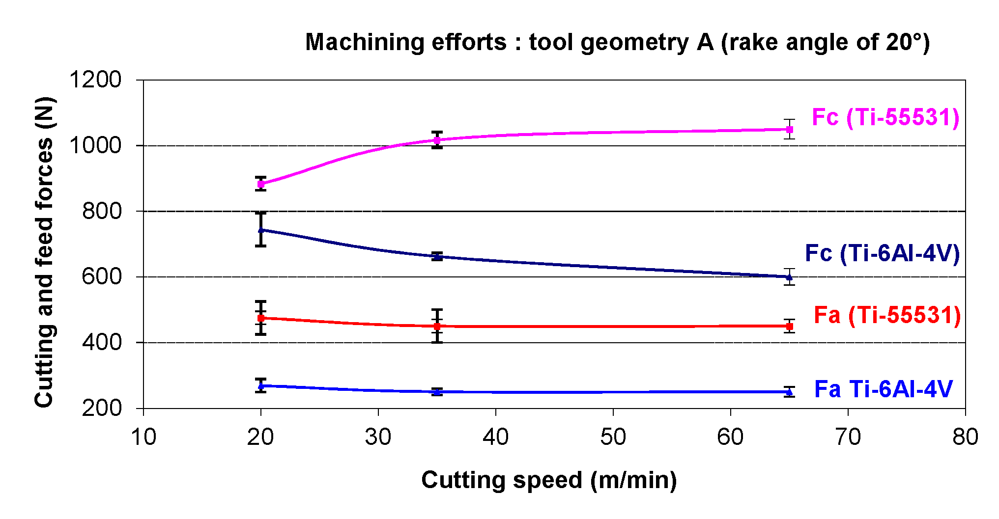
Figure 6, there is a stabilization of cutting forces with high cutting speeds (35 m/min and 65 m/min). However, a slight increase is still noticeable on the cutting force of the Ti-55531 alloy when the cutting speed increases from 20 m/min to 65 m/min. During machining the Ti-6Al-4V alloy with a tool rake angle of 20° (tool geometry “A”) (
Figure 7), a reduction of cutting forces is noticed when the cutting speed increases. This is quite normal considering the thermal softening of the material due to the temperature rise during machining. In other words, when the cutting speed increases, the temperature increases too and this is followed by a decrease in the yield stress level of the alloy. The material deforms under these conditions much more easily and without significant effort. This trend is expected because machining becomes more adiabatic and the heat generated in the shear zone cannot be conducted away during the very short interval of time during which the material passes through this zone. So, the temperature rise softens the material, aiding grain boundary dislocation and thus reducing cutting forces as seen from
Figure 7.
Figure 7.
Cutting forces obtained for Ti-6Al-4V and Ti-55531 with tool geometry “A”.
However, the cutting speed cannot be increased significantly pretext to further reducing the effort because of the significant increase (simultaneously) of the tool wear. On the other hand, an increase in the cutting force level of Ti-55531 with 20° tool rake angle can be observed when increasing the cutting speed. This tendency can be explained by the high strain rate sensitivity of the Ti-55531 alloy.
According to
Figure 6 the comparison between generated cutting forces shows a clear difference between Ti-6Al-4V and Ti-55531. This difference ranges from 12.3%–21.1% for the cutting force and from 30.1%–33.4% for the feed force. This result confirms the poor machinability (previously announced) of the Ti-55531 alloy compared to that of the Ti-6Al-4V under the same machining conditions. The trend given by tools with a rake angle of 0° is confirmed by tools with a rake angle of 20°. The difference may reach 42.9% for some cutting conditions (
V = 65 m/min and α = 20°) (see
Figure 7).
Also, it was found from
Figure 6 and
Figure 7 that the cutting force obtained with the rake angle of 20° was weak compared to that of machining with 0° rake angle at all levels of considered parameters. This has been attributed to the fact that high values of the rake angle may reduce the friction along the cutting edge between tool and workpiece; see the evolution of the friction coefficient in the next subsection (Subsection 4.2).
4.2. Friction Behavior at the Tool-Chip Interface
In this section we focus on the friction, which is the manifestation of the mechanical energy dissipated in the contact between the tool and the workpiece in the form of heat which is responsible for the heating of the cutting edges.
Consequently, to understand physical phenomena during the chip formation, friction processes have to be investigated at the tool-chip interface. The friction co-efficient is an important parameter to characterize the nature of the tool-chip contact and tool wear depending on cutting conditions. According to the famous model of Merchant [
16,
28], the calculation of this parameter can be obtained using cutting forces measurements. In machining, the apparent friction coefficient (or average friction) is often defined as the ratio between the tangential force Ft and the normal force
Fn [
16,
28].
where α is the rake angle; Fc, cutting force; Fa, feed force; Ft, friction force; Fn, normal force.
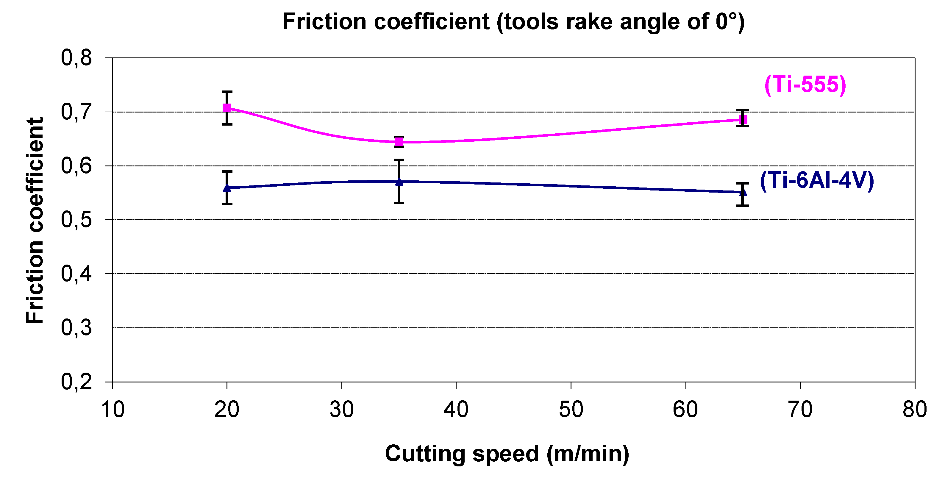
Figure 8 and
Figure 9 show the variation of friction coefficient values at various cutting conditions. These values are calculated using Equation (1). The results of this study show that friction depends on the materials, the cutting temperature and machining conditions (cutting speed, tool geometry,
etc.). In all tests, this parameter is more important with tool geometry “A” (rake angle 20°) compared to those with 0° rake angle (tool geometry “B”). This is due to the reduction of the cutting temperature and contact length. This reduction is often followed by a reduction in frictional forces at the tool-workpiece interface. Low cutting temperatures reduce adhesion tendency of the cutting tool and promote contact area restriction. Reduction of the tool/chip contact length is expected to occur, as well as promotion of the plastic flow at the backside of the chip and overall reduction of temperature.
Figure 8.
Evolution of the friction coefficient in the tool/chip interface. (Tool geometry “B”, rake angle 0°).
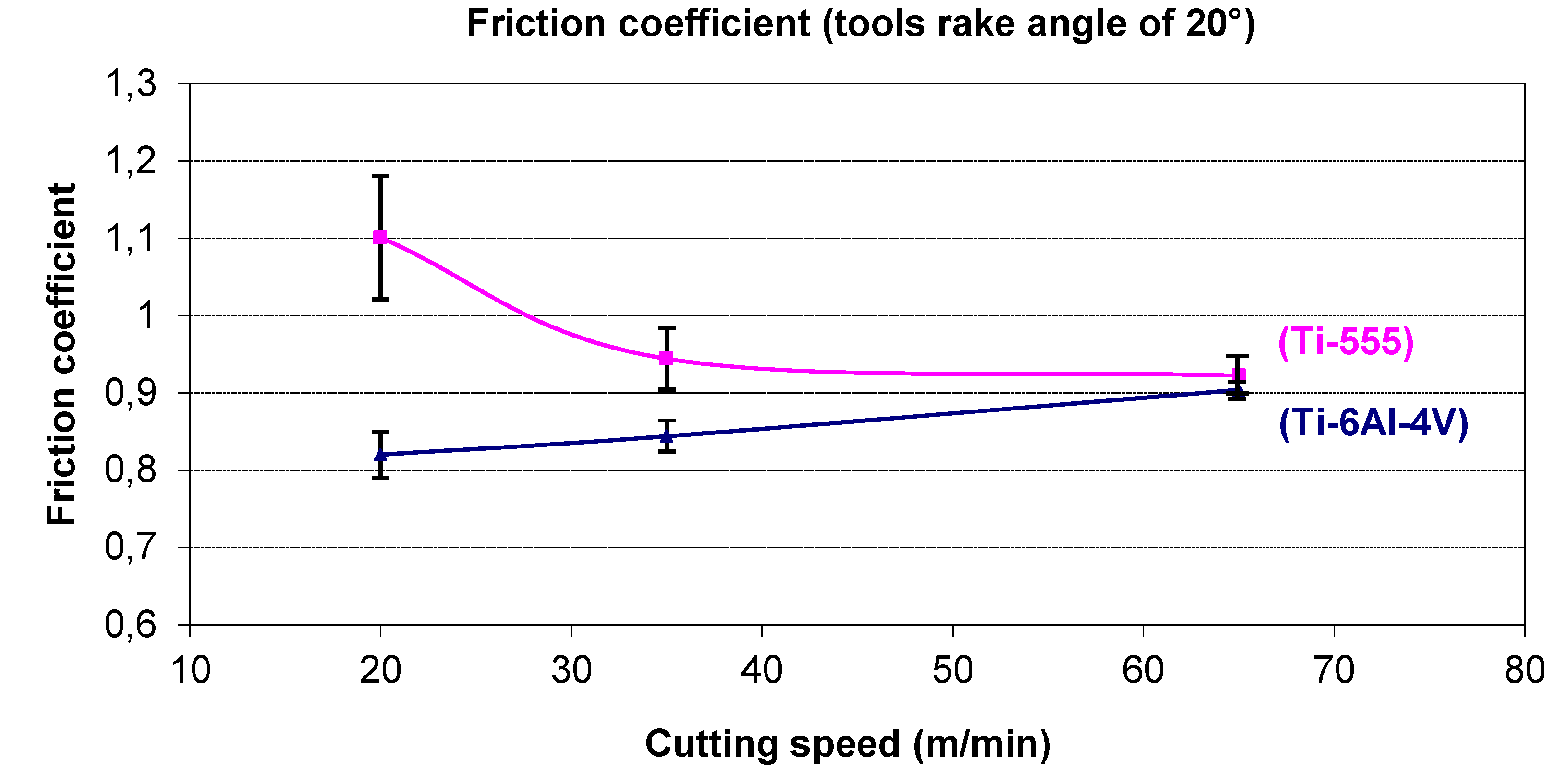
Figure 9.
Evolution of the friction coefficient in the tool/chip interface. (Tool geometry “A”, rake angle 20°).
The results presented above (in
Figure 8 and
Figure 9) show a higher friction coefficient for Ti-55531 compared to Ti-6Al-4V. Thus, the following assumptions can be presented: the contact area at the tool-chip interface can be considered as a sticking contact type for Ti-55531 in the case of machining with tools of 0° rake angle. Therefore, a connection can be made between the nature of the contact (sticking) and the tendency of Ti-55531 to adhere to the cutting face of the tool. In contrast, the tool-chip contact can be of a sliding type in the case of Ti-6Al-4V because of the low values of friction (see
Figure 8).
In the case of machining with tools of 20° rake angle (
Figure 9), the reduction in friction coefficient for the Ti-55531 indicates contact of the sliding type more than the sticking one. Contrary to this trend, increasing friction for the Ti-6Al-4V alloy indicates sticking contact. Also, the increase of the cutting speed (in particular for testing tool geometry 20°) involves stabilization of the friction at high cutting speeds (the friction is a decreasing function of the temperature when the cutting speed increases).
In conclusion, at constant cutting speed, titanium alloy Ti-55531 is more sensitive to adhesion phenomena than Ti-6Al-4V alloy. This may also explain the poor machinability noticed on this alloy.
4.3. Chip Morphology of Titanium Alloys Ti-6Al-4V and Ti-55531
During machining and under the action of the tool cutting edge, the workpiece material undergoes a strong compression and deforms plastically. An intense shear is generated between the tool tip engaged in the material and the workpiece. We analyzed in our investigations this area, called “primary shear zone”, in which the first shear occurs and which induces chip formation.
The chip morphology gives crucial information because it incorporates the material response during machining (mechanical, thermal, thermo-viscoplastic, etc.) and shows the stability of the cutting operation. Moreover, the evolution of cutting forces shows a correlation with the morphology of produced chips. The chip segmentation for example, often leads to a reduction of cutting efforts and the tool-chip contact length. In general, the continuous chip is undesirable in industrial applications. This is due to the generated problems which significantly affect the machining conditions: damage of the cutting edge, forming a heap of material on the cutting area, etc.
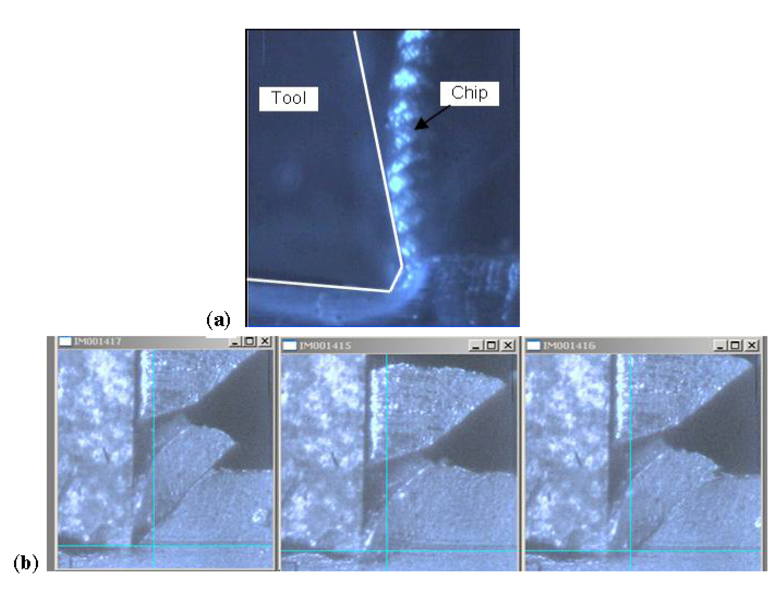
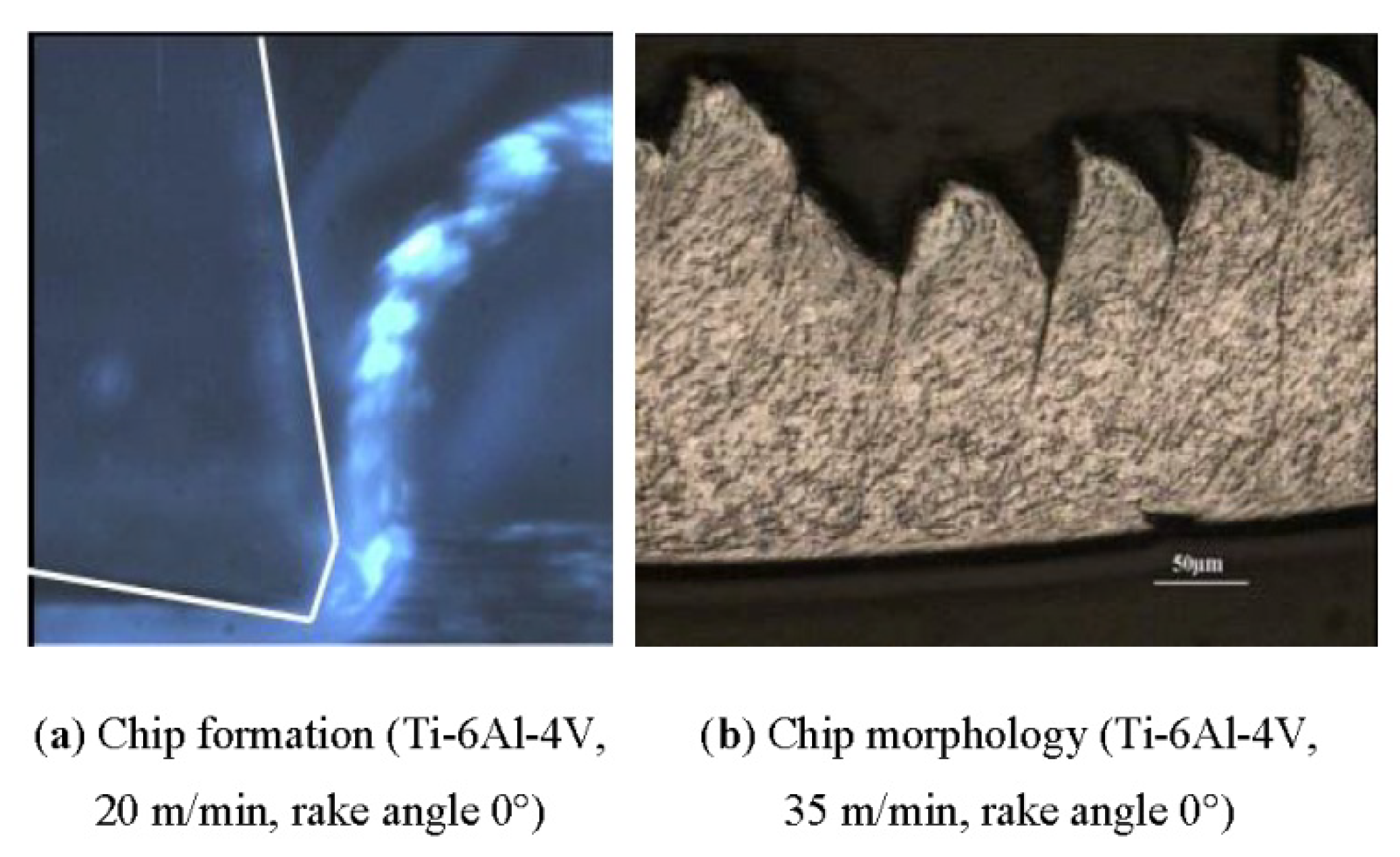
The images obtained by the high speed camera (
Figure 10a) during machining of Ti-6Al-4V show a segmented chip. To confirm this observation further investigation were carried out on chips collected after machining. The micrographs obtained on these chips show a fairly regular segmentation (
Figure 10b). Between two consecutive segments of a single chip, the plastic deformation is very intense and localized in a thin zone of a few micrometers (
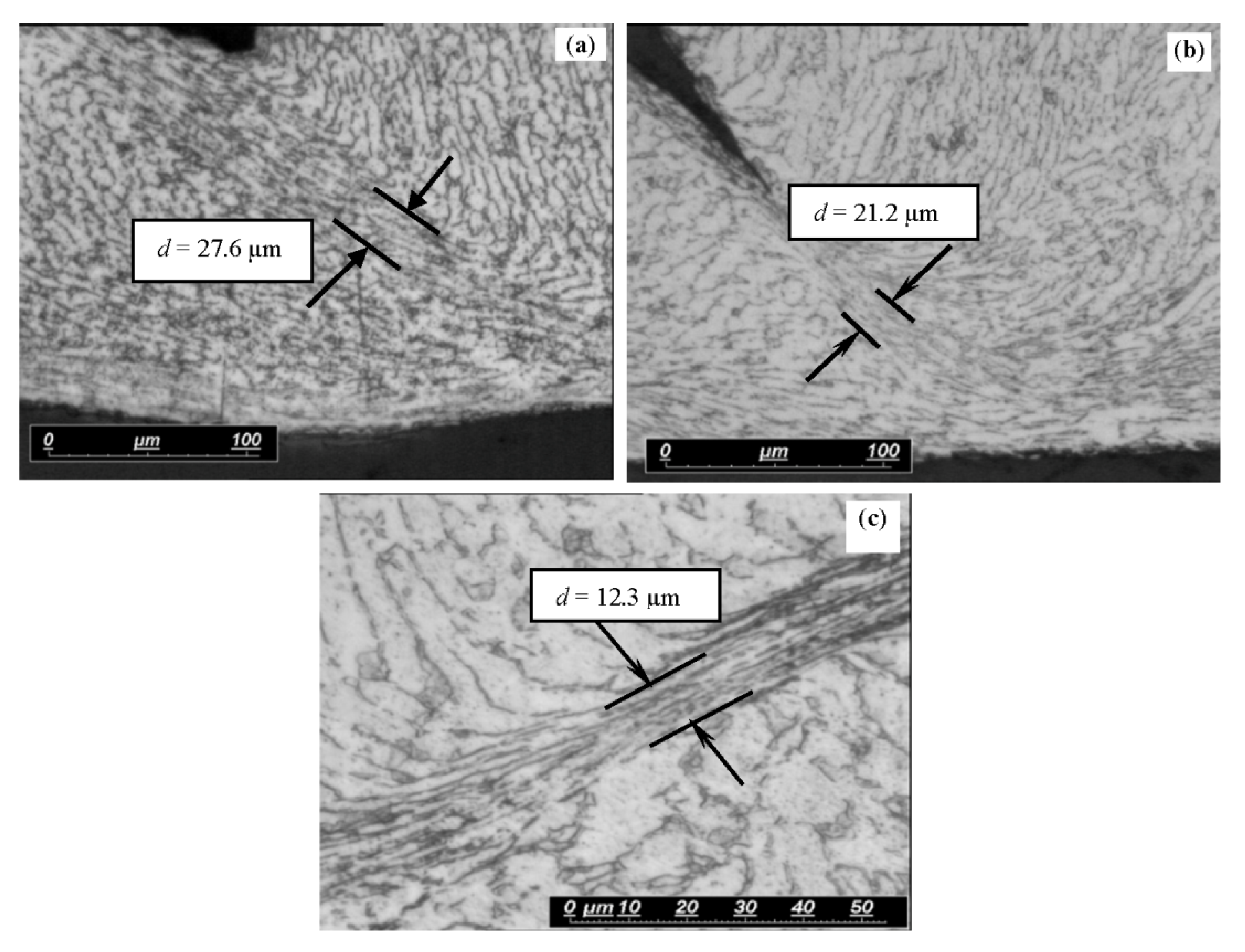
Figure 11). This area where the plastic deformation is localized is known as adiabatic shear band; it is the seat of extreme shear. The thickness of the shear band was measured for different cutting conditions and its evolution was followed depending on the material nature and on the value of cutting speed. The conclusion of this analysis is that the increase of cutting speed means that the shear bands are more refined in the chip body (
Figure 11).
Figure 10.
Ti-6Al-4V alloy chip formation (a) (by high speed camera), and morphology (b).
Figure 11.
Evolution of the adiabatic shear band thickness depending on the cutting speed for Ti-6Al-4V. (a) 20 m/min, (b) 35 m/min, (c) 65 m/min. Tests without lubrication.
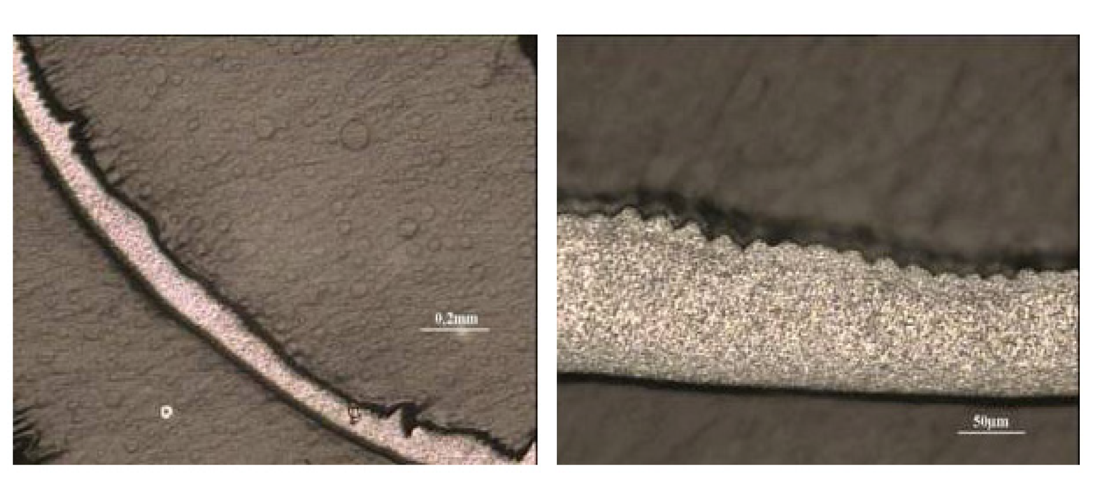
Unlike Ti-6Al-4V, Ti-55531 chips have a morphology slightly scalloped with a rather continuous nature. They are also characterized by highly irregular thicknesses. This morphology retains the same characteristics at different cutting speeds and for the different geometries tested (
Figure 12).
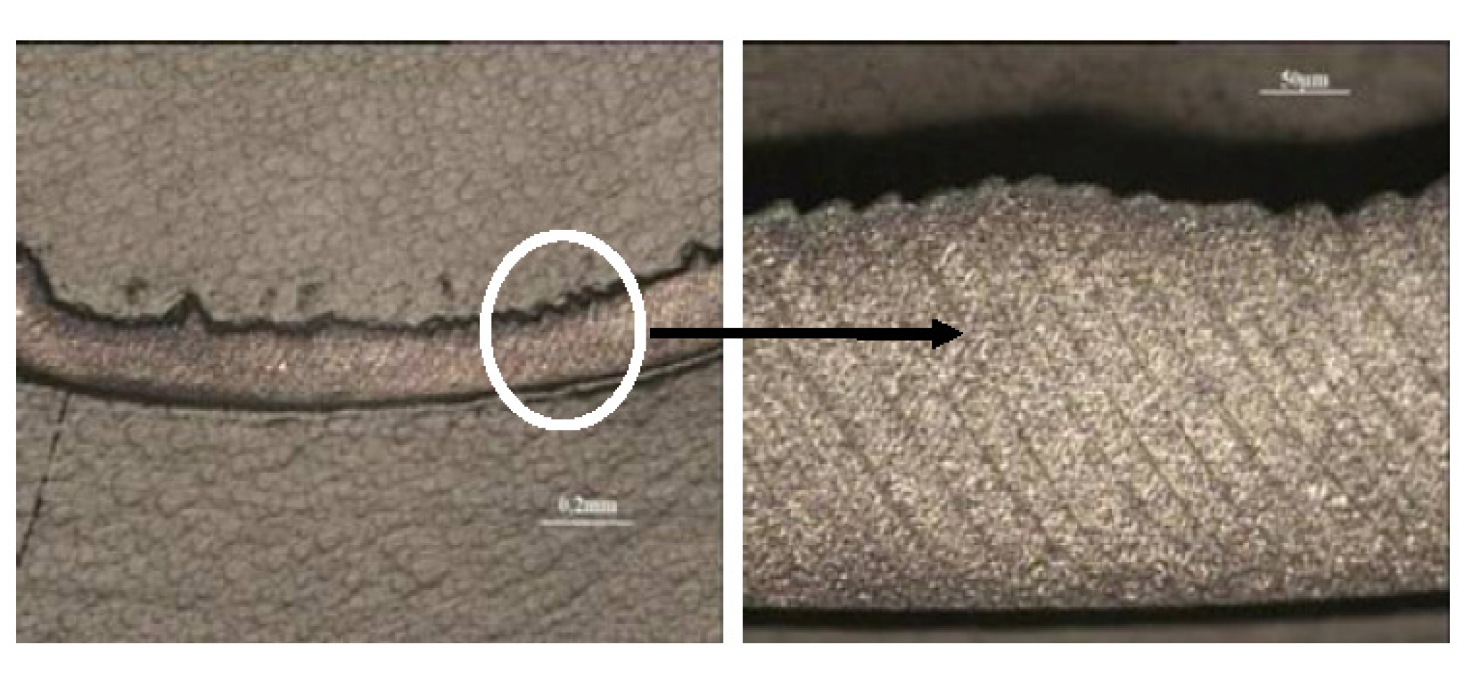
Figure 13 shows the appearance of pronounced adiabatic shear bands without cracking or separation between the chip segments. So, the segmentation being synonymous with lower cutting efforts, during machining Ti-55531 alloy means cutting efforts will not decrease even if cutting speed increases. This explains the poor machinability of Ti-55531 compared to the Ti-6Al-4V alloy.
Figure 12.
Chip morphology of Ti-55531 (20 m/min, tool A).
Figure 13.
Chip morphology of Ti-55531 (35 m/min, tool A).
Finally, under the same machining conditions and tool geometries, it can be seen that Ti-6Al-4V forms segmented chips more easily than Ti-55531. This segmentation allows improved machinability resulting in lower cutting forces.
4.4. Microstructure Effect
Chips obtained after machining and presented in
Figure 14 were mounted with epoxy so that they stood on their edge in order to make the cross section after polishing straight across their length. The polished chips were etched with Kroll’s reagent to reveal their microstructures. Micrographs of examined chips in
Figure 14 show clearly the deformation phenomenon inside the microstructure of both materials during the chip formation. However, the deformation process is different from one material to another. It can be noted here that both chips given by machining Ti-6Al-4V and Ti-55531 alloys were obtained with the same cutting conditions.
The examination of the deformed microstructure reveals very fine sizes of grains in the β alloy (Ti-55531). In this material, the deformation process is localized in a very thin layer called primary shear zone while in the Ti-6Al-4V alloy the same process of deformation occurs in the whole microstructure, i.e., in α, β and α + β phases. Indeed, chips of the Ti-6Al-4V alloy have a very different microstructure compared to the initial Ti-6Al-4V alloy. For Ti-55531 chips, apart from the primary shear zone, there is a very similar microstructure to that observed in the initial Ti-55531 alloy.
Figure 14.
Microstructure of the chip material obtained after machining.
5. Wear Mechanisms of Cutting Tools
In this section the different modes of tool degradation have been analyzed when machining titanium alloys Ti-6Al-4V and Ti-55531. Wear can be discussed in relation to the nature of the material involved, its metallurgical and thermophysical characteristics, machining conditions and the tool coating. The wear analysis is based on observations of the scanning electron microscope (SEM, JEOL (EUROPE) SAS., Paris, France) equipped with an energy X-ray spectrometer (EDS, JEOL (EUROPE) SAS., Paris, France) in correlation with measurements obtained with an optical profilometer. The damage modes of tool characterization was conducted through the measurement of:
-
the worn tool-chip contact length,
-
the thickness and extent of the formed adhesion layers,
-
the depth and width of the crater formed on the tool rake face.
The determination of the worn contact length was performed by analyzing the SEM micrographs of tool-chip contact zones. These areas have previously been identified by measuring the distance between the cutting edge and the limit of the worn portion on the interface. Furthermore,
in-situ analysis (using a high speed camera CCD) has shown that the chip winding is forward of the tool. Thus, the footprint of the wear on the tool surface represents the contact between the latter and the chip being formed.
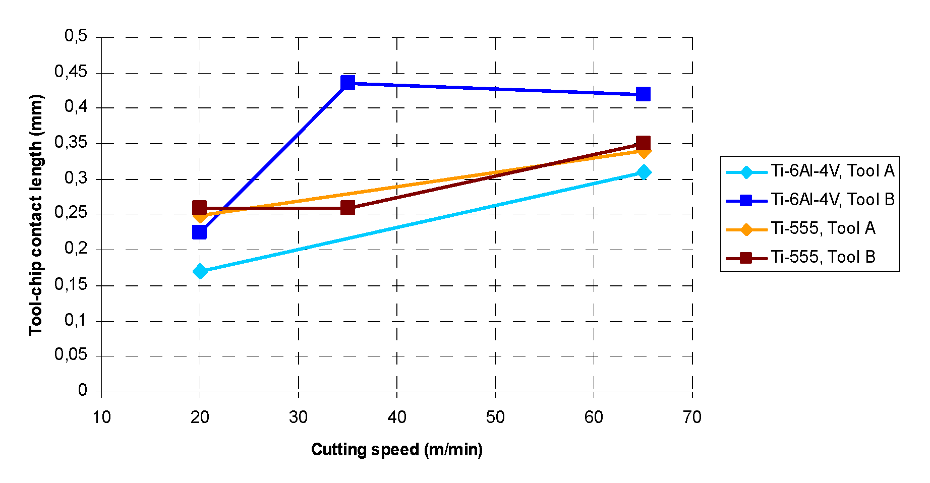
Figure 15 summarizes the different values of the recorded worn contact length.
The results show that the increase of the cutting speed induces an increase of the worn contact length. In the case of Ti-6Al-4V the variation is more remarkable. For both tested geometries, it is around 45%. This confirms the analysis of the heat-softening behavior of material. Indeed, and as mentioned above, Ti-6Al-4V has a lower thermal conductivity compared to Ti-55531 to high temperatures (around 30%). The stored heat thus generates greater softening for Ti-6Al-4V than for Ti-55531. The contact between the tool and the Ti-6Al-4V alloy then extends over a larger area of the tool surface relative to the Ti-55531 alloy. For the Ti-55531 alloy, the variation of the contact area is about 25% when the cutting speed increases from 20–65 m/min. The presence of the betagenic element chromium in the Ti-55531 microstructure improves the deformation resistance of this alloy at high temperatures. Therefore, Ti-55531 machinability is degraded as a function of temperature.
Figure 15.
Evolution of the tool-chip worn contact length.
In conclusion, it can be said that the affected area by wear in the case of Ti-55531 is greater than in the case of Ti-6Al-4V at identical cutting conditions and tool geometry.
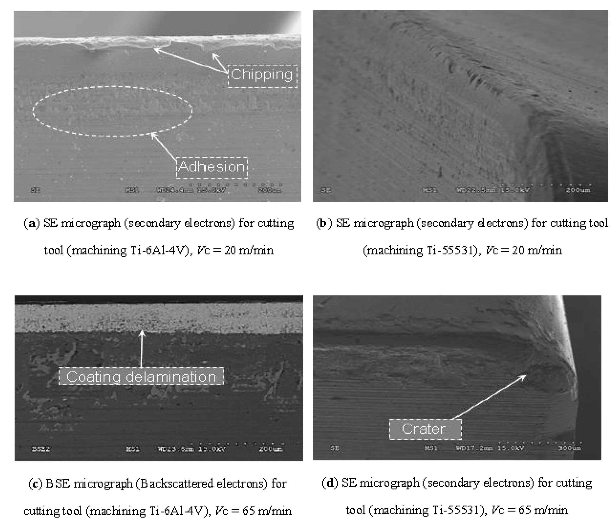
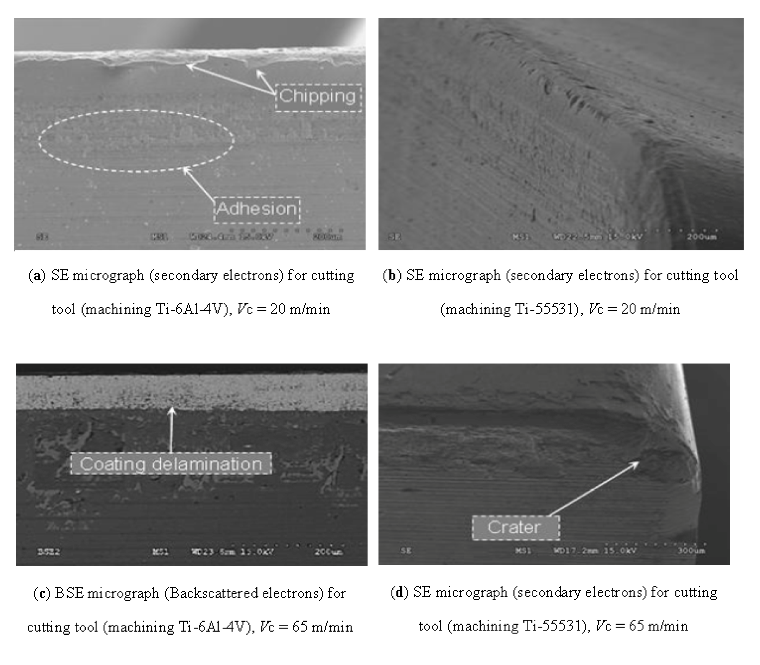
It has been observed from the SEM analysis in
Figure 16 and
Figure 17 that the cutting tool encounters severe thermal and mechanical loading when machining titanium alloys. This can be supported by the level of the measured cutting temperature (about 750–800 °C for
V = 65 m/min) and high recorded cutting forces (about 1000 N). Also, other works previously showed that the cutting pressure can also attain large values (about 1–1.5 GPa), [
10,
29]. The high stresses and high temperatures generated close to the cutting edge have great influence on the tool wear rate and on tool life.
Figure 16.
SEM images (BSE and SE micrographs) of the tool wear when machining Ti-6Al-4V and Ti-55531 alloys with different cutting speeds (rake angle 0°).
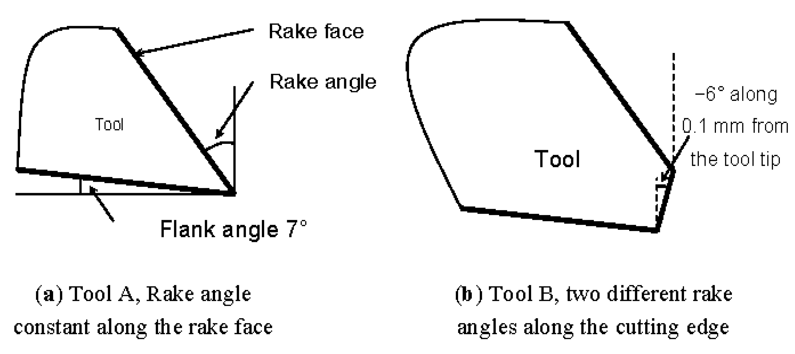
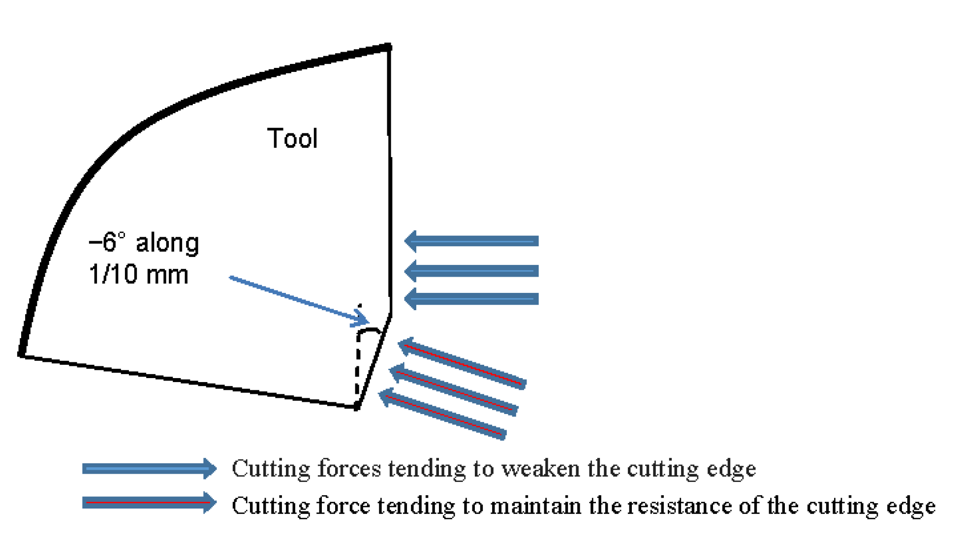
The tool geometry “B” has been designed primarily to give a negative rake angle to the front of the cutting edge (about 0.1 mm). This allows steering the cutting forces inwardly of the tool (
Figure 18). The aim of this treatment undergone by the cutting edge is to enhance the tool wear resistance. However, the test results showed a significant deterioration of machinability in terms of cutting forces compared to the tool geometry “A”.
Figure 17.
SEM images of the tool wear when machining Ti-6Al-4V and Ti-55531 alloys (rake angle 20°).
Figure 18.
Orientation of machining efforts on a tool edge.
From
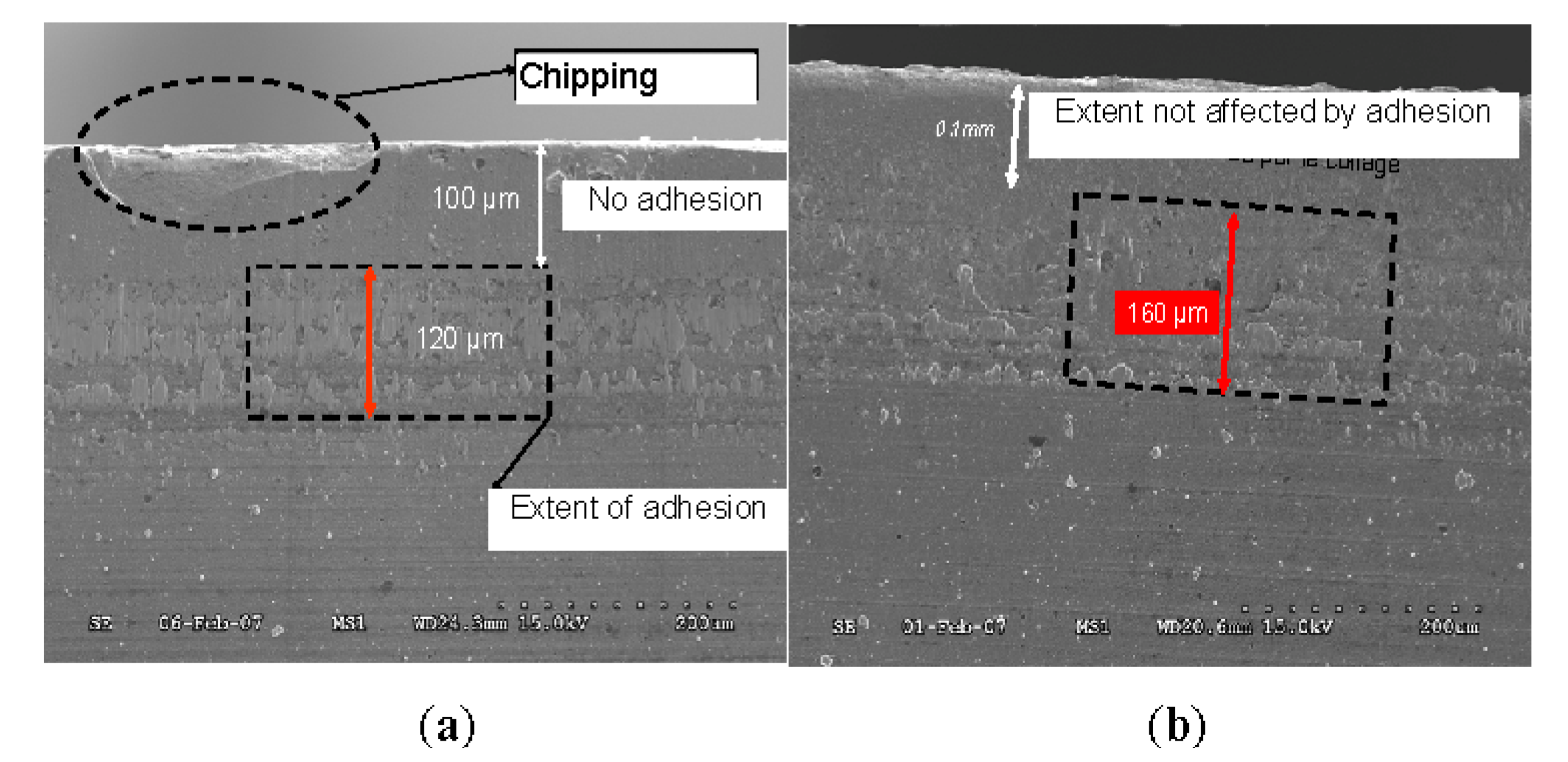
Figure 19, at identical machining conditions, it can be noted that the extent of the negative rake angle of 0.1 mm is not degraded by the adhesion process but only by abrasion wear. The most tangible explanation of this observation is that this area of the tool displaces (or rejects) the material rather than machining.
Figure 19.
Adhesion extent on tool geometry B (Vc = 20 m/min), (a) Ti-6Al-4V; (b) Ti-55531.
In the case of tools with 0° rake angle, the extent of the area affected by the wear is greater for Ti-55531 than for Ti-6Al-4V. At 20 m/min for example, it is about 120 µm for the Ti-6Al-4V while about 160 μm for Ti-55531 (
Figure 19a,b). This is mainly due to the fact that the increase in cutting forces for the Ti-55531 generates higher stress on the cutting edge. The hardness of the material also contributes to the heavy wear edge. Micrographs also show delamination of the coating layer on the tool surface during machining Ti-6Al-4V at 65 m/min. This is not the case for the Ti-55531 alloy under the same cutting speed (
Figure 16a–d).
The delamination phenomenon is difficult to analyze because it can have both thermal and mechanical origins. This is partly due to the complex interaction between various physical factors that control delamination: intrinsic properties of the coating, the tool and those of the interaction between the substrate, coating and workpiece. However, it is possible to attribute the origin of delamination to chemical reactions. During cutting of Ti-6Al-4V, adhesion occurring at the tool-chip interface is the main harbinger of the delamination problem.
At low cutting speeds, adhesive wear mode was observed during machining titanium alloys (
Figure 16). The location of the adhesion wear is greater in the case of Ti-6Al-4V compared to Ti-55531. For Ti-55531, the wear results show that the predominant degradation process is abrasion wear (
Figure 16b).
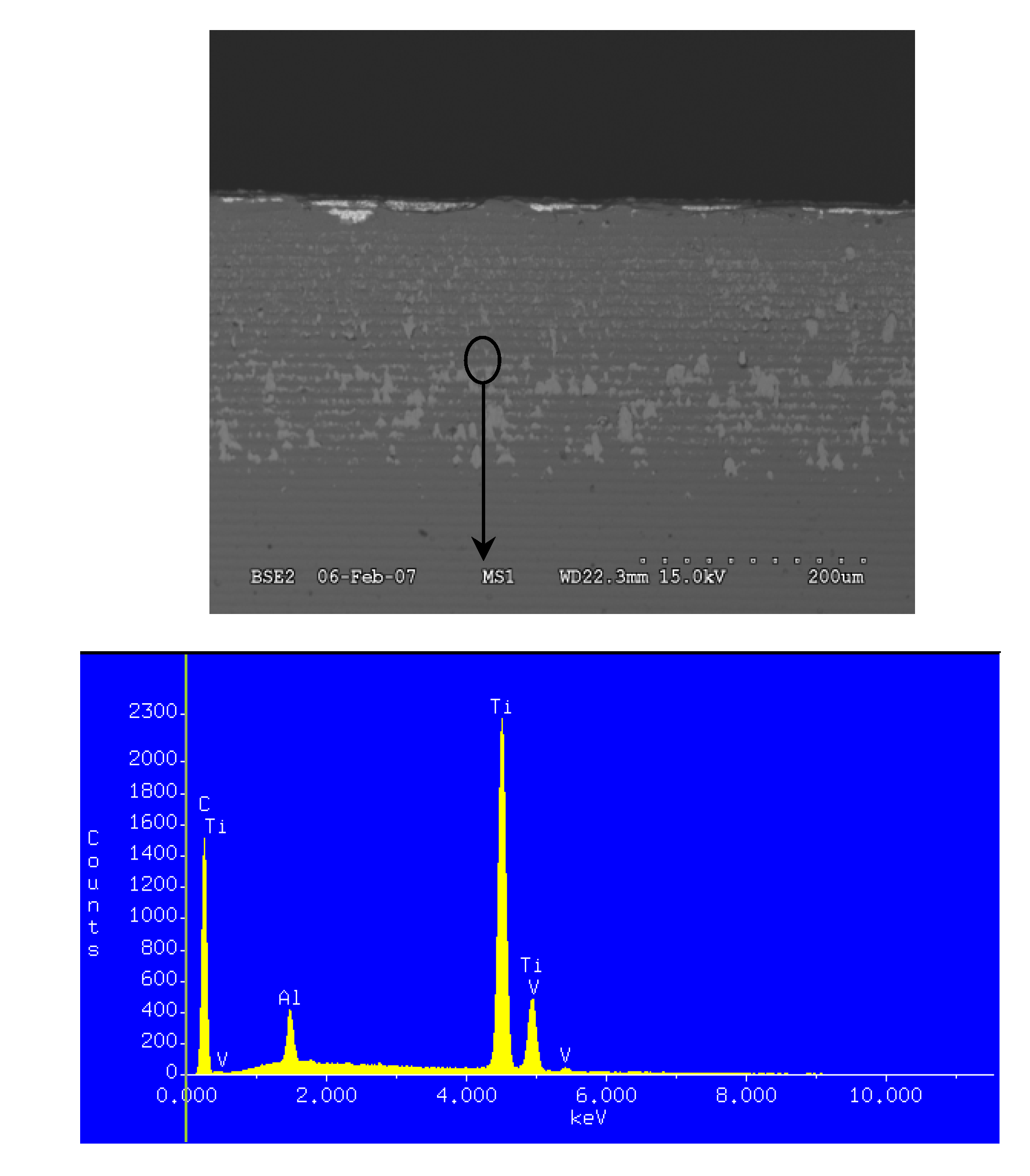
As shown by the EDS analysis illustrated in
Figure 20, particle debris are deposited on the tool surface during machining Ti-6Al-4V as successive layers when chips scroll to the surface. This leads to the adhesive wear mode. The latter is highlighted by the change in the tool geometry and debonding of the coating (
Figure 17c).
Figure 20.
Energy X-ray spectrometer (EDS) measurements of the adhered material (Ti-6Al-4V) on the rake face. V = 20 m/min, rake angle 0°.
During machining Ti-55531 at 65 m/min, a process of cracking starts resulting in a collapse of the cutting edge (
Figure 17d). This is produced by the combined effect of high pressures and large strain rates in the tool (substrate and coating). Adhesive wear layers on the tool surface were measured using a profilometer in the case of machining Ti-6Al-4V.
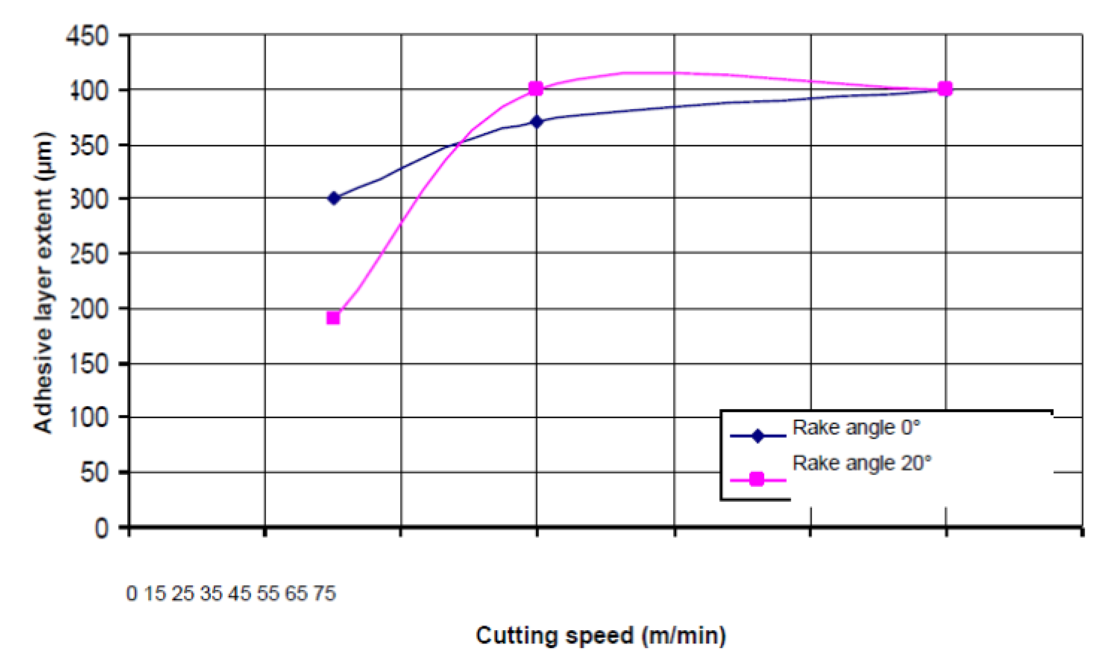
Figure 21 shows the evolution of the adhesive layer extent depending on cutting speed.
Figure 21.
Evolution of the adhesive layer extent on the tool surface during machining Ti-6Al-4V with different cutting speeds.
It appears from this result that the adhesive wear increases with the cutting speed and is stabilized at high speeds. This may be due to the diffusion process between titanium alloy and the cutting tool at the interface. In some cases and under the combined effect of pressure and temperature, welds are formed between tool and chip. With permanent mechanical stress (during machining), these welds are broken thereby causing chipping of the cutting surface. The irregularity on the tool surface can constitute attachment points for chip debris. By accumulating, they eventually form a detrimental macroscopic deposit on the cutting edge. This phenomenon has been observed for cutting tools when machining the Ti-6Al-4V alloy under low cutting speeds (see
Figure 16a and
Figure 17a).
In the case of Ti-6Al-4V, the average grain size is about 10 µm and the measured microhardness is in the range of 317 HV
0,2. For Ti-55531, the microstructure is homogeneous and the grain size is about 1 μm with a microhardness of 379 HV
0,2. From a metallurgical point of view, the major difference between Ti-6Al-4V and Ti-55531 is due to fineness of the microstructure. This generally leads to a higher mechanical strength. However this will strongly influence the machinability of the machined material and then tool wear as confirmed by Powell and Duggan [
30] and by Arrazola
et al. in [
31]. In addition, Ti-55531 is an alloy of the β-type (near-β titanium alloy), with the presence of betagenic elements, such as chromium, for example, which limits the ability of the material to deform during machining.
Based on the results from the experimental tests we can give some ideas of how to improve the machining of the two alloys studied in this article. It is possible to increase the cutting speed in the case of machining Ti-6Al-4V, which causes increase in temperature at the interface tool/material and therefore a significant softening of the machined material. Consequently cutting efforts will be lower. This solution cannot be applied in the case of Ti-55531 because of its high strain rate sensitivity. On the other hand, the improvement of the machining of Ti-6Al-4V can be carried out by changing the geometry of the tool. Increasing rake angle facilitates chip flow; this will cause reduction in cutting efforts and pressure. This improvement can also be applied to the machining of Ti-55531 alloy.
6. Conclusions
In this research work, a detailed experimental approach for the comprehension of machining titanium alloys has been presented. Several analyzes (SEM, EDS, Infrared camera, high-speed camera CCD and profilometer analysis) confirmed that differences in machinability and microstructure of tested titanium alloys can have an important impact on tool wear. The low machinability of titanium alloys due to the low thermal conductivity and high microhardness of these materials leads to severe and premature tool wear. The machining of titanium alloy Ti-55531 has been compared with that of Ti-6Al-4V alloy. To do this study, the mechanical, thermal, metallurgical and physico-chemical aspects were analyzed in depth.
During the evolution of the machining efforts depending on cutting conditions and tool geometry, a decrease of cutting forces is noted for the case of Ti-6Al-4V when the cutting speed increases. This decrease is due to the thermal softening of the material under the effect of plastic deformation and cutting temperature. In other words, during the machining of Ti-6Al-4V, its yield stress decreases and therefore improves the machinability for this material. For Ti-55531, this reduction has not been clearly identified. Unlike the Ti-6Al-4V alloys, the chip morphology of Ti-55531 shows a work hardening behavior. This means that flow stress increases during machining making its machinability more difficult.
From a metallurgical point of view, the major difference between Ti-6Al-4V and Ti-55531 is the fineness of the microstructure. The latter is automatically accompanied by higher strength, better ductility and toughness. It can therefore be said that Ti-55531 has better fatigue resistance which greatly penalizes its machinability. Another difference from Ti-55531 relative to Ti-6Al-4V is the fact that the microstructure of Ti-55531 contains a volume fraction of the larger β phase. This increases its hardness while also reducing its machinability.
Results have also shown that the friction between the tool and the workpiece is close to one for the case of Ti-55531 alloy compared to Ti-6Al-4V. This means that during Ti-55531 machining the contact at the chip-tool interface is of a sticky type, thereby giving impetus to the Ti-55531 alloy to more easily adhere to the cutting tool face. This type of contact also influences the thermal field which is greater in the case of Ti-55531 (temperature for Ti-55531 about 800 °C, for Ti-6Al-4V about 670 °C). In addition, at the high temperatures, Ti-55531 alloy conducts heat better than the Ti-6Al-4V alloy. The low thermal conductivity of Ti-6Al-4V promotes chip segmentation and therefore the reduction of machining efforts. For the Ti-55531 alloy, its higher conductivity allows it to further evacuate the stored heat, but at the same time it decreases its ability to soften and thereby deteriorates its machinability. Thus, it has been found that the area affected by the wear in the case of Ti-55531 is greater than in the case of Ti-6Al-4V under the same machining conditions and for the same tool geometry. The current study also showed that the tool geometry has a significant influence on the machinability of both titanium alloys. With a rake angle of 0°, the difference of machinability is only about 12% between Ti-55531 and Ti-6Al-4V and remains constant regardless of the cutting speed. With geometry of 20°, this difference is greater and reached high levels for high cutting speeds (approximately 34.7% to 65 m/min).


