
Titanium Matrix Composite Ti/TiN Produced by Diode Laser Gas Nitriding


Welding Department, Silesian University of Technology, Konarskiego 18A, 44-100 Gliwice, Poland
Metals 2015, 5(1), 54-69; https://doi.org/10.3390/met5010054
Submission received: 11 November 2014
/
Accepted: 4 January 2015
/
Published: 9 January 2015
(This article belongs to the Special Issue Titanium Alloys)
Abstract
:A high power direct diode laser, emitting in the range of near infrared radiation at wavelength 808–940 nm, was applied to produce a titanium matrix composite on a surface layer of titanium alloy Ti6Al4V by laser surface gas nitriding. The nitrided surface layers were produced as single stringer beads at different heat inputs, different scanning speeds, and different powers of laser beam. The influence of laser nitriding parameters on the quality, shape, and morphology of the surface layers was investigated. It was found that the nitrided surface layers consist of titanium nitride precipitations mainly in the form of dendrites embedded in the titanium alloy matrix. The titanium nitrides are produced as a result of the reaction between molten Ti and gaseous nitrogen. Solidification and subsequent growth of the TiN dendrites takes place to a large extent at the interface of the molten Ti and the nitrogen gas atmosphere. The direction of TiN dendrites growth is perpendicular to the surface of molten Ti. The roughness of the surface layers depends strongly on the heat input of laser nitriding and can be precisely controlled. In spite of high microhardness up to 2400 HV0.2, the surface layers are crack free.
1. Introduction
Titanium alloys are attractive structural materials, compared to other light alloys and modern high strength steels as investigated by A. Grajcar and A. Kurc [1,2,3]. However, due to poor tribological properties of titanium and titanium alloys, their service life may not be satisfactory under certain conditions, as reported by A. Biswas and P. Schaaf [4,5,6,7,8]. The low surface hardness and wear resistance limit the application of titanium alloys under conditions of friction and contact loads [9,10,11].
Tribological properties of titanium alloys may be improved or modified by coatings on the surface, changing the microstructure of surface layers, or thermochemical treatments such as nitriding, carburizing, oxidizing or nitro-oxidizing [12,13,14]. Nitriding of surface layers of titanium alloys is one of the most widely used thermochemical treatments in industry [15,16]. The methods of surface nitriding of titanium alloys such as plasma, physical vapor deposition (PVD), chemical vapor deposition (CVD), salt-bath nitriding and ion implantation have been developed and applied for many years [17,18,19].
One of the most promising and effective methods for improving the surface characteristics and properties of titanium alloys is laser surface treatment in a nitrogen atmosphere or rich in nitrogen-laser gas nitriding (LGN) [20,21].
This is the result of the large chemical affinity of titanium for nitrogen at elevated temperatures, particularly in a liquid state. This feature leads to the in situ synthesis of metal matrix composite (MMC) in the surface layer with a high content of titanium nitrides in the titanium metallic matrix (precisely Titanium Matrix Composite-TMC). Composite surface layers of titanium alloys modified in such a way have a significantly higher wear resistance compared to conventional titanium alloys, as well as to other wear-resistant surface layers reinforced by hard carbides or ceramic nano particles in metallic matrix produced by laser alloying or cladding, as those investigated by D. Janicki [22,23].
Despite the fact that the first trials of laser nitriding of titanium were carried out by Katayama [1] in the eighties of the last century, the process is still being developed. Initially trials of titanium LGN were carried out only by gaseous CO2, mainly continuous wave (CW) lasers [1,24]. The fundamental problem during laser nitriding of titanium in the liquid state reported by most researchers was high surface roughness and cracking of the nitrided titanium, as well as short fatigue life [1,7,24]. Other researchers have noted that both the type and also the mode of laser beam affect significantly the nitriding process and have a strong influence as well on the characteristics and properties of the nitrided surface. L. Xue and M. Islam [24] found that in terms of surface finish and cracking severity, a solid state Nd:YAG (neodymium-doped yttrium aluminum garnet; Nd:Y3Al5O12) laser in pulse mode (emitted at 1.06 µm) was better than a CO2 laser in continuous wave mode (emitted at 10.6 µm).
Edson Costa Santos et al. [11] showed the difference between laser gas nitriding by Nd:YAG laser in CW, Q-sw and pulsed modes. Naofumi Ohtsu et al. [20] investigated the surface hardness of titanium modified by laser irradiation at different wavelengths in a nitrogen atmosphere. They found that the effect of irradiation is clearly different for different wavelengths, and reported that craters formed by the 532-nm laser were deeper than those formed by the 1064-nm laser for the same remaining parameters.
E. Carpene et al. [25] investigated the laser nitriding of different metals by various lasers with different wavelengths in a range from 0.3–3.0 µm. They indicated that for some metals the wavelength strongly effects the irradiation and efficiency of the nitriding process. A.L. Thomann et al. [15] investigated the surface nitriding of titanium and aluminum by laser-induced plasma. They used a pulsed CO2 laser (emitting at 1.06 µm) and pulsed excimer XeCl (emitting at 308 nm), and found that the synthesized layers exhibit differences that depend on the type of laser used.
Due to the dynamic development of laser devices and laser technologies, new types and new generations of lasers are currently available [21,26]. One of the new generations of lasers introduced for material processing is the high power diode laser (HPDL) characterized by a rectangular laser beam spot and a uniform energy distribution across the beam spot [5,6,16,22]. The number of publications on titanium nitriding by HPDL lasers is still very limited but every author points to the high potential and benefits of this type of laser in surface treatment, especially in titanium gas nitriding [4,5,6,16,19,20].
Results of investigations on the nitriding of titanium alloys by HPDL lasers show the advantages of the HPDL lasers over the Nd:YAG and CO2 lasers with a circular laser beam. M. Gołębiewski et al. [19] investigated different processes of titanium nitride production and revealed that the lowest residual stresses were measured for the surfaced nitrided by HPDL with a rectangular beam spot. The residual stresses in the layers produced by HPDL are compressive in nature and about ten times lower (−300 to −800 MPa) compared to the stresses in layers produced by pulsed laser deposition (−500 to −8000 MPa). A. Biswas et al. [6] investigated the laser gas nitriding of Ti6Al4V alloy applying a high power diode laser. They also found that the residual stresses are mainly compressive in nature and strongly depend on process parameters; moreover the lowest compressive residual stresses started from 50 MPa.
To summarize, the advantages of the specific type of diode lasers beam for surface processing of metals are as follows:
- -
- high absorption in the very near infrared band of laser radiation, especially compared to the gaseous CO2 lasers (even several times higher) makes the diode laser beam a very efficient heat source,
- -
- -
- rectangular shape of the laser beam spot,
- -
- uniform heating of the metal surface across the processing track as a result of the above two advantages.
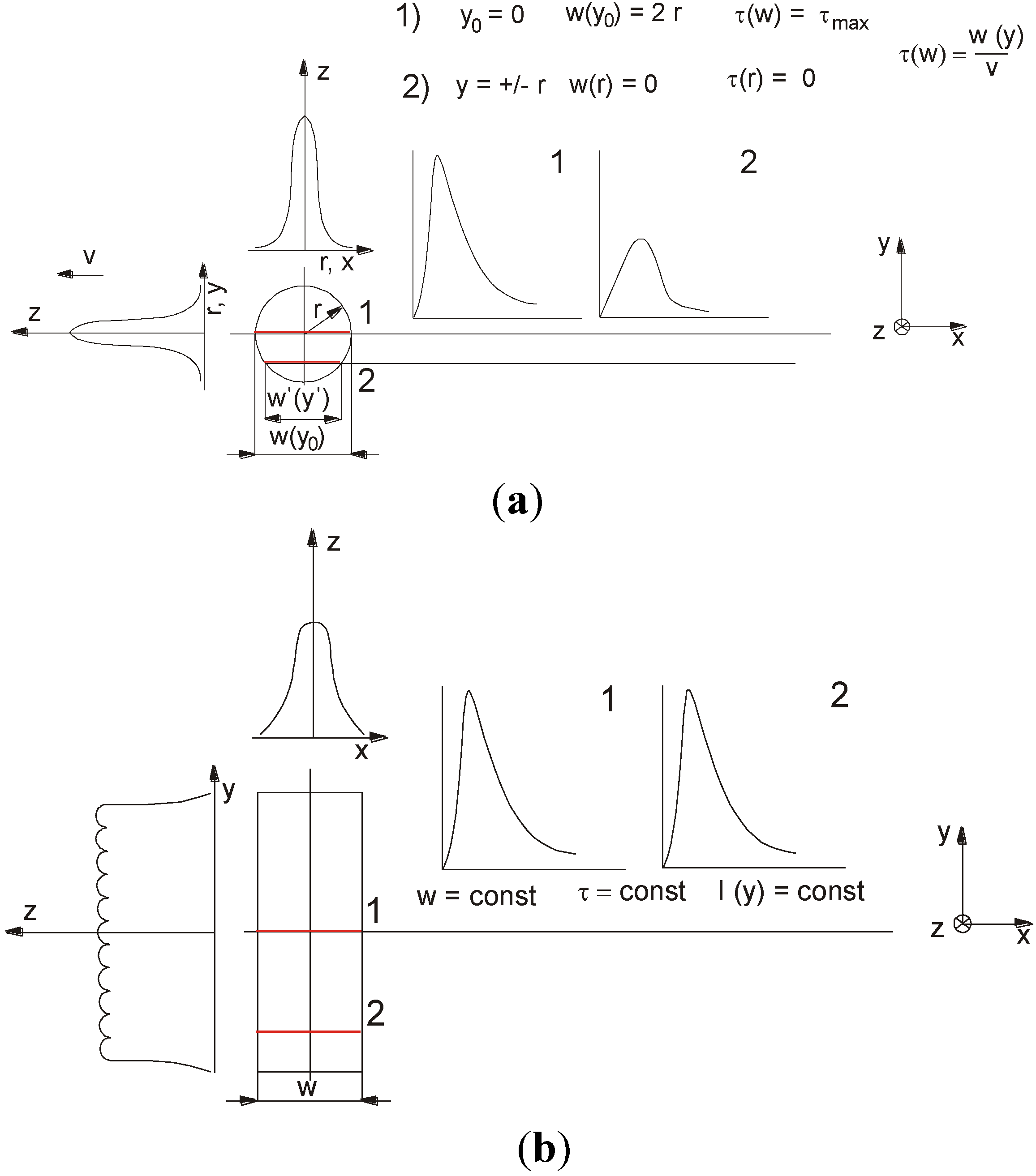
The rectangular shape of a laser beam spot is very profitable in the case of surface treatment, when the heating intensity, temperature range, and a thermal cycle on the treated surface are crucial parameters. When the rectangular laser beam is moved linearly on the treated surface and the laser beam is emitted in CW mode, the irradiation time (i.e., time of beam interaction on the metal surface τ) is constant across the processing track, unlike in the case of the circular laser beam of commonly used gaseous CO2 or solid state YAG lasers, as shown in Figure 1 and Figure 2b. The time of beam interaction on the treated metal surface “τ” is defined as the ratio of the beam width (or length) “w” to the scanning speed “v”:
where:
τ = w/v (s)
w, is laser beam width (or length, mm) in the case of a rectangular or square beam and a diameter in a case of a circular beam (just for calculation of the maximum interaction time τmax, as illustrated in Figure 1a),
v, is scanning speed (mm/s).
Figure 1.
The differences in surface heating by (a) the circular laser beam with a Gaussian single mode of energy distribution (TEM00) and (b) the rectangular laser beam with uniform energy distribution (Top-hat, multimode profile, shown also in Figure 2).
Figure 1.
The differences in surface heating by (a) the circular laser beam with a Gaussian single mode of energy distribution (TEM00) and (b) the rectangular laser beam with uniform energy distribution (Top-hat, multimode profile, shown also in Figure 2).

2. Experimental Section
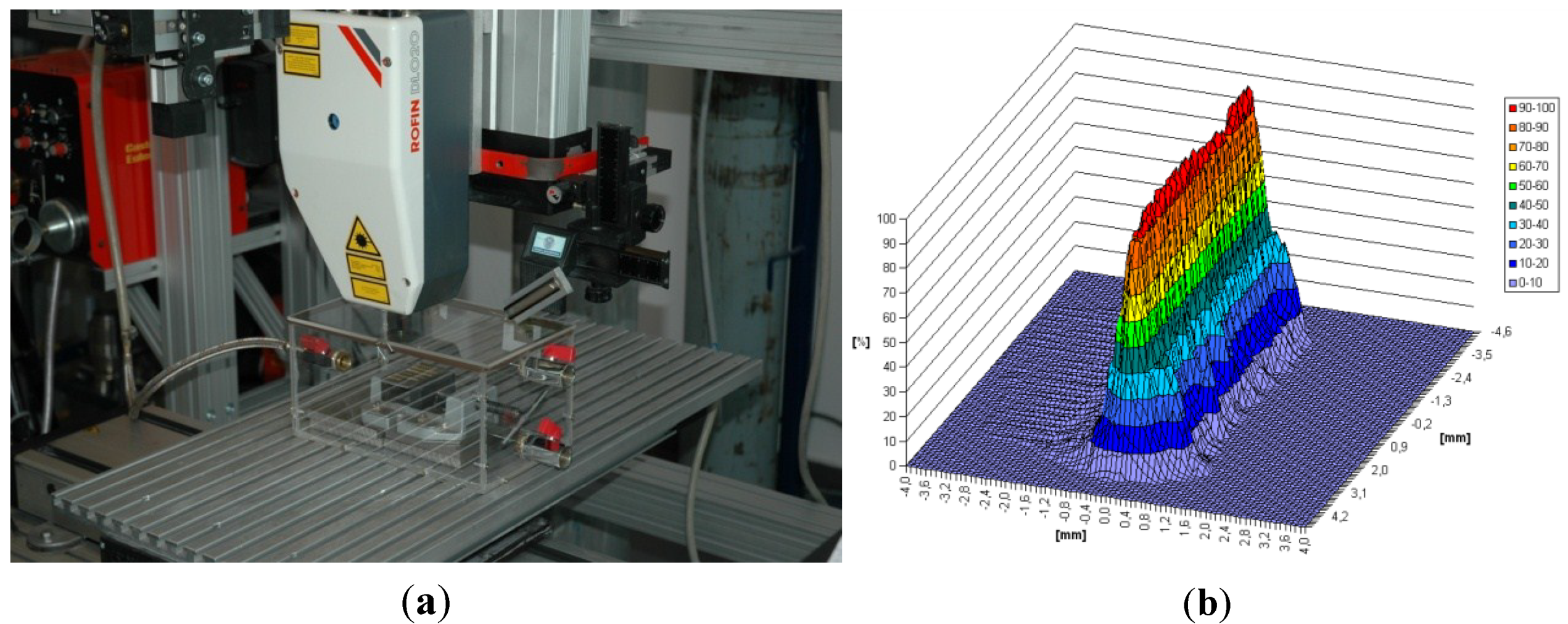
The experiments of laser gas nitriding were carried out by means of a prototype, numerically controlled stand, equipped with the continuous wave high power direct diode laser HPDDL Rofin DL020 with unique characteristics, emitting a laser radiation at a dominant wavelength 808 nm and with a rectangular beam spot. Additionally, the rectangular laser beam spot with a width of 1.8 mm and a length of 6.8 mm is characterized by multimode, uniform intensity of laser radiation across the beam spot, as show in Figure 2b and given in Table 1.
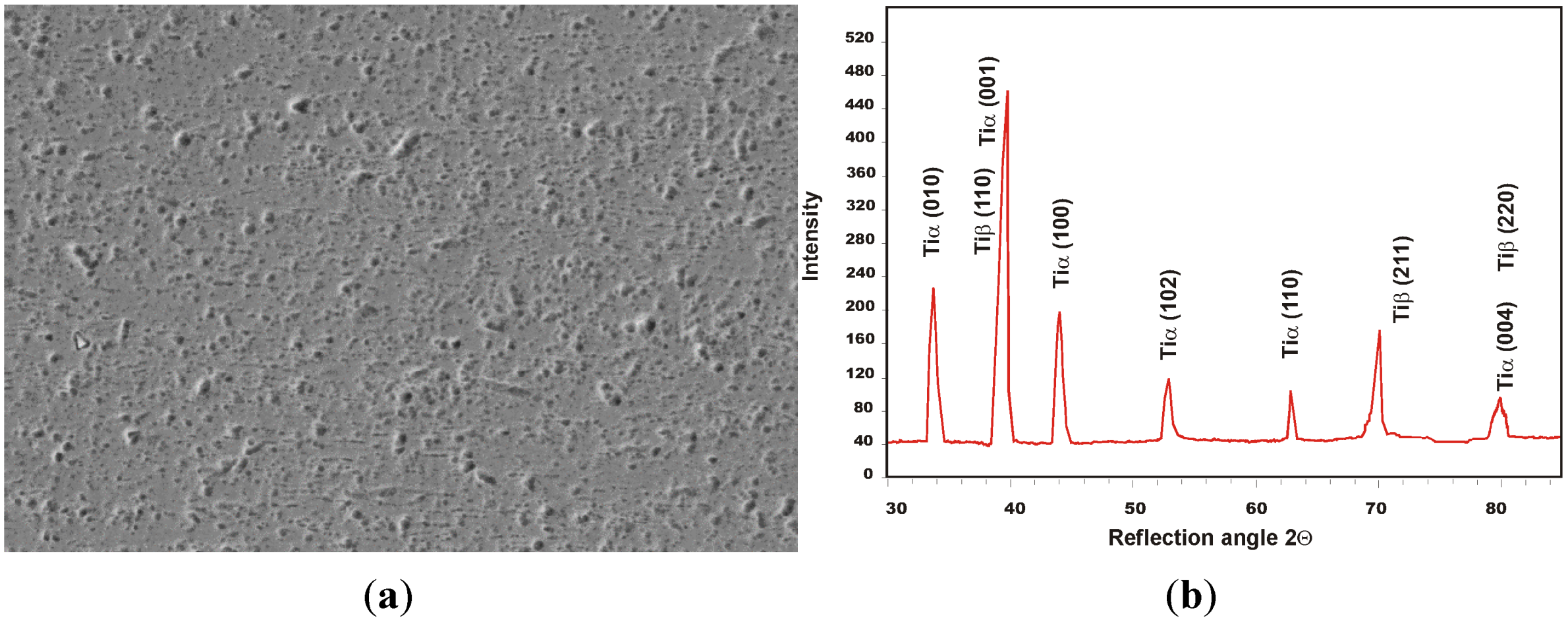
The specimens of titanium alloy Ti6Al4V were cut into coupons 50.0 × 100.0 mm from a hot-rolled sheet with a thickness of 3.0 mm. The structure of the base metal (BM) of titanium alloy Ti6Al4V is shown in Figure 3. Surfaces of the specimens were ground by 180-grade SiC paper to remove oxides and other contaminations from the surface. Prior to nitriding, the surfaces were degreased by acetone. The specimens of titanium alloy were placed in a gas chamber filled up with gaseous nitrogen of 99.999% purity (Figure 2a).
For precise control of the gas atmosphere in the gas chamber, an electronic system of gas delivery was used and the nitrogen flow rate was kept at 10.0 L/min at the pressure 1.0 atm. Flow of the nitrogen through the gas chamber was switched on 90 s prior to the laser nitriding process in order to totally remove the air from the gas chamber (Figure 2a).
Figure 2.
(a) A view of the experimental setup equipped with the continuous wave high power direct diode laser (HPDDL) ROFIN DL 020; (b) 3D laser beam intensity profile (energy distribution) determined at the focal plane (beam spot) for the applied laser.
Figure 2.
(a) A view of the experimental setup equipped with the continuous wave high power direct diode laser (HPDDL) ROFIN DL 020; (b) 3D laser beam intensity profile (energy distribution) determined at the focal plane (beam spot) for the applied laser.


| Parameter | Value |
|---|---|
| Wavelength of the laser radiation (nm) | 808 ÷ 940 * (±5) |
| Maximum output power of the laser beam (kW) | 2.2 |
| Range of laser power (kW) | 0.1 ÷ 2.2 |
| Focal length (mm) | 82/32 |
| Laser beam spot size (mm) | 1.8 × 6.8 or 1.8 × 3.8 ** |
| Range of laser power intensity (kW/cm2) | 0.8 ÷ 32.5 |
* the dominant wavelength is 808 nm; ** size of the beam spot when an additional lens is applied with a focal length of 32 mm.
Figure 3.
(a) Scanning electron micrograph (SEM) and (b) XRD spectrum of the as-received titanium alloy Ti6Al4V specimen 3.0 mm thick (α + β phases).
Figure 3.
(a) Scanning electron micrograph (SEM) and (b) XRD spectrum of the as-received titanium alloy Ti6Al4V specimen 3.0 mm thick (α + β phases).

The nitrided surface layers on titanium alloy specimens were produced as single stringer beads. The rectangular laser beam spot was focused on the top surface of specimens and set perpendicularly to the direction of scanning. Laser gas nitriding (LGN) tests of the titanium alloy Ti6Al4V surface were conducted over a wide range of processing parameters, at different laser power and different scanning speed. The processing parameters, as well as the detailed technological conditions are given in Table 2.
Table 2.
Parameters of laser gas nitriding of titanium alloy Ti6Al4V specimens 3.0 mm thick by the high power direct diode laser ROFIN DL 020.
| Sample No. | Scanning speed (mm/min) (mm/s) | Output laser power (W) | Heat input (J/mm) | Power * density (W/cm2) | Time of laser beam interaction (s) | Thickness of TiN layer (mm) | Remarks |
|---|---|---|---|---|---|---|---|
| P1 | 200 (3.33) | 500 | 150 | 4 × 10³ | 0.54 | 0.04 ± 0.001 | NC, US |
| P2 | 600 (10.0) | 1800 | 180 | 1.5 × 10⁴ | 0.18 | 1.08 ± 0.037 | NC, US |
| P3 | 400 (6.66) | 1200 | 180 | 0.98 × 10⁴ | 0.27 | 0.98 ± 0.028 | NC |
| P4 | 200 (3.33) | 600 | 180 | 0.49 × 10⁴ | 0.54 | 0.90 ± 0.003 | NC, UW |
| P5 | 200 (3.33) | 700 | 210 | 0.57 × 10⁴ | 0.54 | 1.08 ± 0.007 | NC |
| P6 | 1000 (16.66) | 2000 | 120 | 1.6 × 10⁴ | 0.108 | 0.26 ± 0.009 | NC, US |
| P7 | 900 (15.0) | 1800 | 120 | 1.5 × 10⁴ | 0.12 | 0.24 ± 0.008 | NC, UW |
| P8 | 600 (10.0) | 1200 | 120 | 0.98 × 10⁴ | 0.18 | 0.28 ± 0.007 | NC |
| P9 | 300 (5.0) | 600 | 120 | 0.49 × 10⁴ | 0.36 | 0.05 ± 0.001 | NC, US |
| P10 | 800 (13.33) | 2000 | 150 | 1.6 × 10⁴ | 0.135 | 0.79 ± 0.02 | NC |
| P11 | 600 (10.0) | 1500 | 150 | 1.2 × 10⁴ | 0.18 | 0.67 ± 0.021 | NC |
| P12 | 1000 (16.66) | 1500 | 90 | 1.2 × 10⁴ | 0.108 | 0.14 ± 0.003 | NC, US, HR |
| P13 | 800 (13.33) | 1200 | 90 | 0.98 × 10⁴ | 0.135 | 0.17 ± 0.002 | NC |
| P14 | 600 (10.0) | 900 | 90 | 0.74 × 10⁴ | 0.18 | 0.13 ± 0.002 | NC, UW |
| P15 | 400 (6.66) | 600 | 90 | 0.49 × 10⁴ | 0.27 | 0.02 ± 0.001 | NC, UW, SF |
| P16 | 400 (6.66) | 1800 | 270 | 1.5 × 10⁴ | 0.27 | 1.74 ± 0.04 | NC |
| P17 | 200 (3,33) | 900 | 270 | 0.74 × 10⁴ | 0.54 | 0.67 ± 0.018 | NC, US |
| P18 | 2000 (33.33) | 2000 | 60 | 1.6 × 10⁴ | 0.054 | 0.19 ± 0.005 | NC, US |
| P19 | 1800 (30.0) | 1800 | 60 | 1.5 × 10⁴ | 0.06 | 0.09 ± 0.001 | NC, US |
| P20 | 1500 (25.0) | 1500 | 60 | 1.2 × 10⁴ | 0.072 | 0.14 ± 0.006 | NC |
| P21 | 1200 (20.0) | 1200 | 60 | 0.98 × 10⁴ | 0.09 | 0.098 ± 0.002 | NC, US |
| P22 | 900 (15.0) | 900 | 60 | 0.74 × 10⁴ | 0.12 | 0.12 ± 0.004 | NC, US |
| P23 | 1200 (20.0) | 1800 | 90 | 1.5 × 10⁴ | 0.09 | 0.11 ± 0.005 | NC, US |
Remarks: laser beam spot size 1.8 × 6.8 mm, focal length 82.0 mm, nitrogen gas flow rate 10.0 L/min; NC, no crack; US, uneven surface; HR, high roughness of the bead face; UW, uneven width of the bead; SF, smooth surface of the bead face; * in laser physics, the power density of laser beam is defined as a beam intensity.
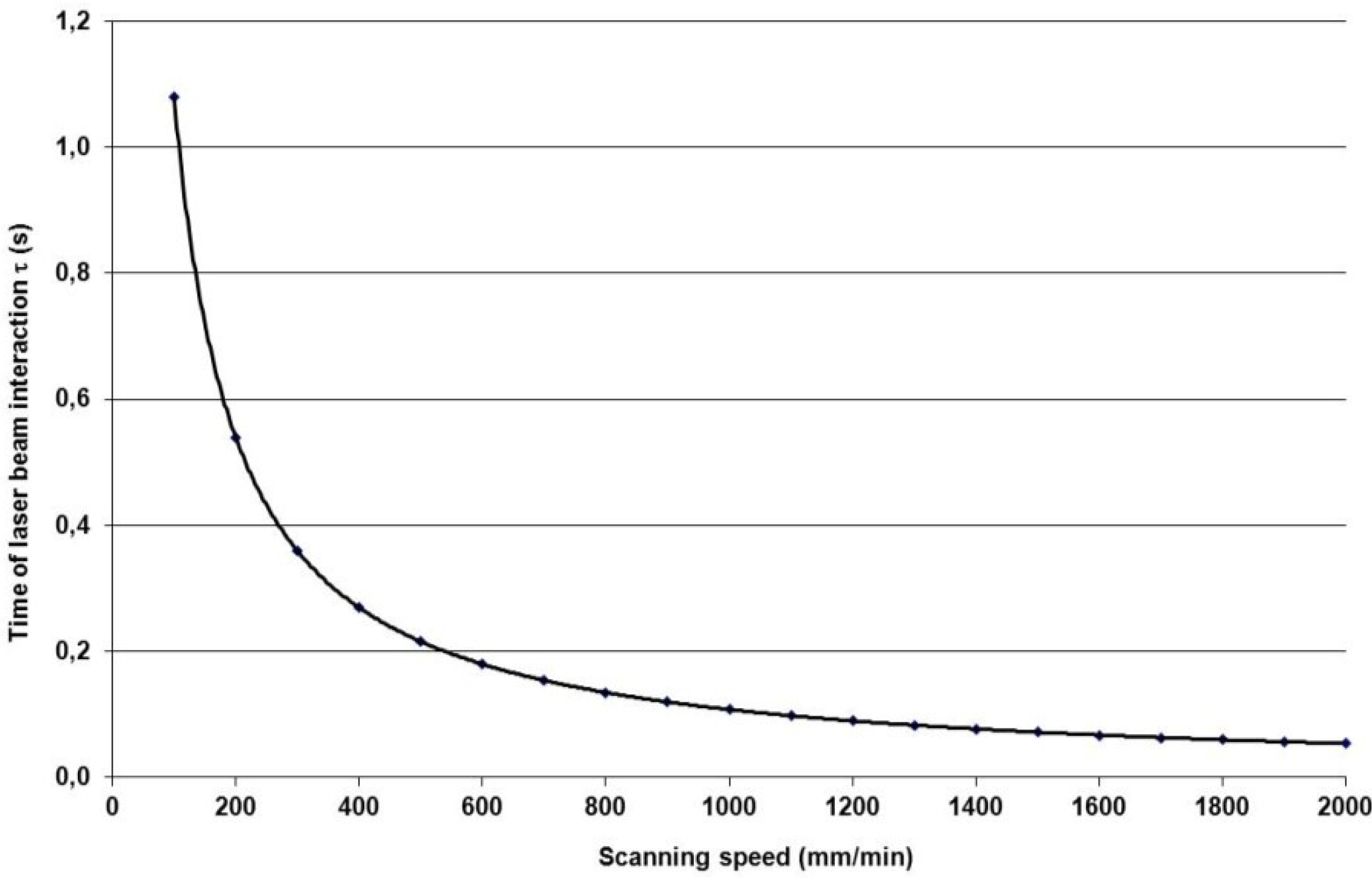
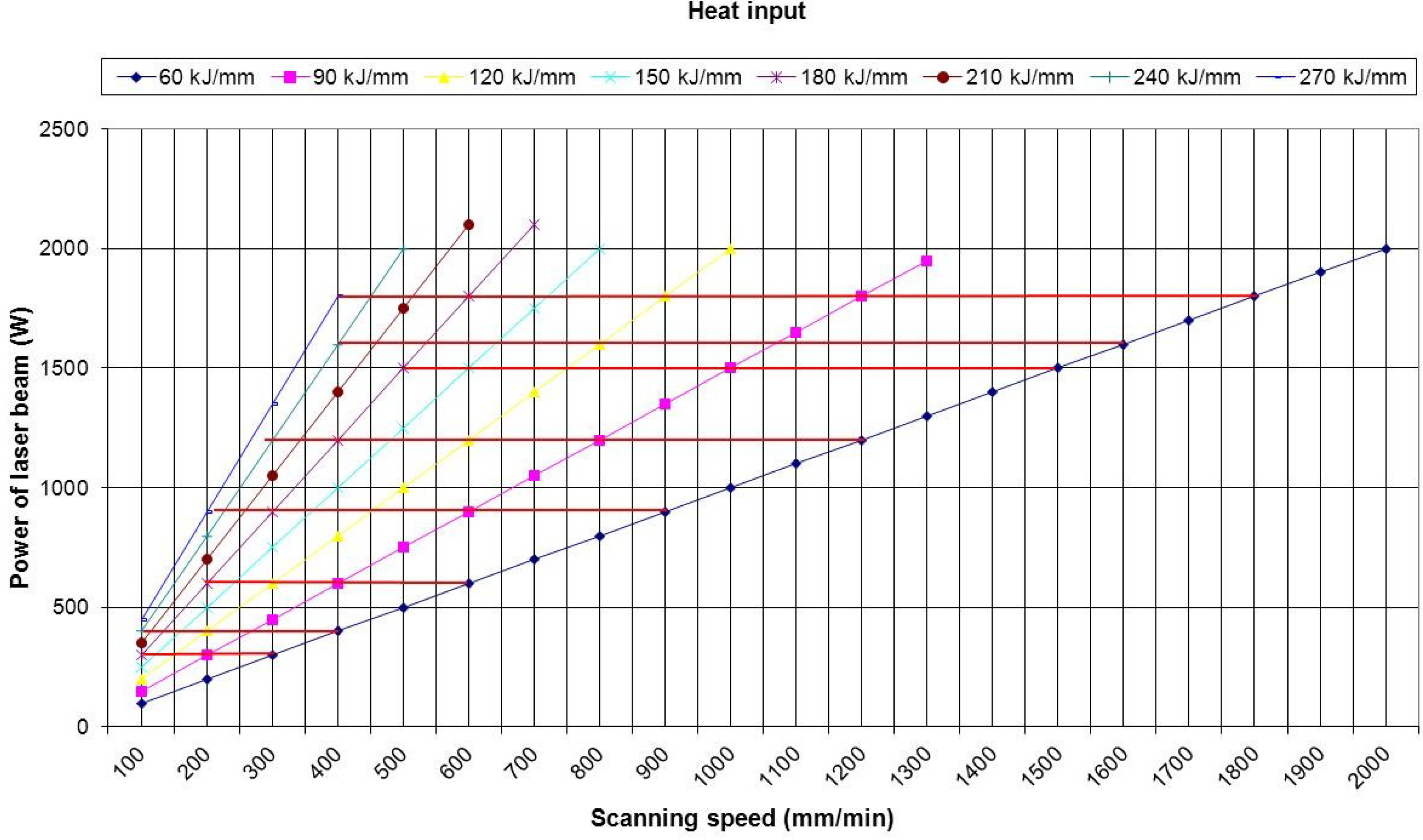
In order to compare the surface layers nitrided at the same heat input (J/mm) but at different beam interaction time τ (s), the experiment (trial of nitriding) was planned on the basis of the relationship between laser power and scanning speed illustrated in Figure 4 and Figure 5. The time of laser beam interaction on the treated surface of titanium alloy was calculated for the beam spot width of 1.8 mm according to Equation (1). In welding and surface treatment technologies, when the moving heat source is applied, the term of heat input “Ev” (J/mm) is commonly used and it is defined as the power of a heat source “P” (W) divided by the processing speed “v” (mm/s) (e.g., welding or scanning speed):
Ev = P/v (J/mm)
Therefore the linear relationships between laser power and scanning speed for different heat inputs were determined as illustrated in Figure 5. These relationships allowed the selection of processing parameters over a wide range of laser power and scanning speed for precisely set and constant heat input.
Figure 4.
Relationship between the interaction time τ of laser beam and scanning speed v determined for the rectangular beam spot of a width of 1.8 mm.
Figure 4.
Relationship between the interaction time τ of laser beam and scanning speed v determined for the rectangular beam spot of a width of 1.8 mm.

Figure 5.
Graphic illustration of the relationship between laser power and scanning speed for a constant heat input.
Figure 5.
Graphic illustration of the relationship between laser power and scanning speed for a constant heat input.

The surface layers produced during laser gas nitriding of the titanium alloy were examined by visual testing, roughness, and surface topography analysis, next the samples were cut for cross-section examinations. Roughness measurements were carried out by means of a portable surface roughness tester SJ-210 Surftest (Mitutoyo Corporation, Kanagawa, Japan) according to ISO 4288 standard. Whereas the surface topography was measured and analyzed by an optical, non-contact Profilograph Micro Prof 100 FRT (FRT GmbH, Bergisch Gladbach, Germany). The microstructure and phase composition of base metal and surface layers were examined and analyzed by optical and scanning electron microscopy SEM (Carl Zeiss, Oberkochen, Germany), EBSD (EDAX Inc., Mahwah, NJ, USA) and X-Ray diffraction (Panalitycal, Almelo, The Netherlands). Microhardness was measured and determined on the cross-section of surfaced layers. The influence of the parameters of the laser gas nitriding on surface topography, microhardness, structure and the shape of surface layers was analyzed. The results are given in Table 2 and Table 3, and also in Figure 3, Figure 4, Figure 5, Figure 6, Figure 7, Figure 8, Figure 9, Figure 10, Figure 11, Figure 12, Figure 13.
3. Results and Discussion
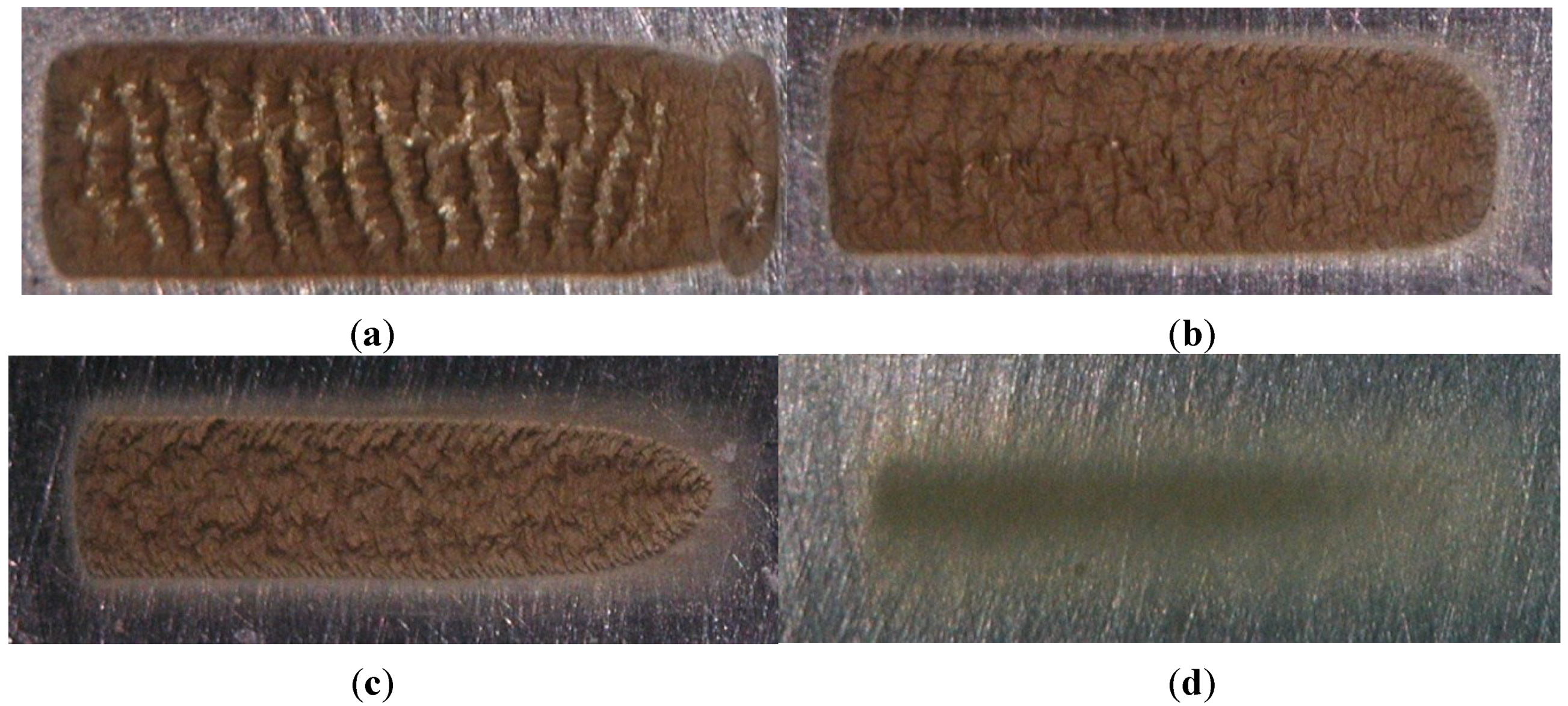
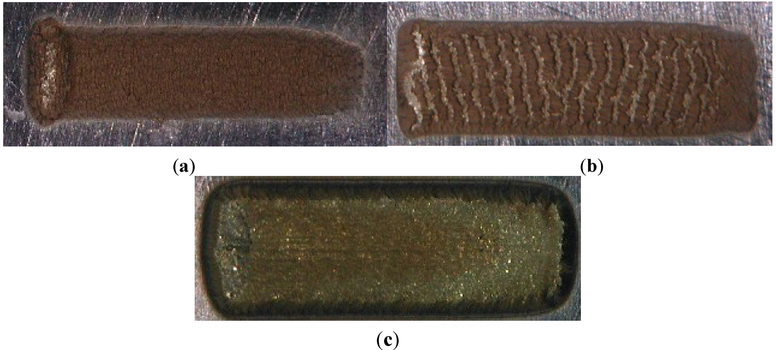
The surface layers of titanium alloy Ti6Al4V specimens 3.0 mm thick after laser gas nitriding (LGN) in an atmosphere of pure nitrogen are matt, and all present the golden shine characteristic of titanium nitrides (Figure 6 and Figure 7). The topography and roughness of the surface layers depend strongly on the process parameters of laser gas nitriding, i.e., laser power and scanning speed (Figure 6 and Figure 7, Table 3). The results of laser gas nitriding conducted at different process parameters clearly indicate that the heat input, as a process parameter, is not sufficient for identifying and predicting the properties of nitrided surface layers (Figure 6). The nitrided surface layers produced at the same heat input of 90 J/mm but at different laser power output, different scanning speed, thus different time of laser beam interaction, as well as different power density, have very different surface topography, roughness, and thus different morphology (Figure 6, Table 2). In the range of high scanning speed over 1200 mm/s and simultaneously high laser power over 1200 W (relatively low heat input, in general below 90 J/mm) the nitrided surface is very even, flat and smooth (Figure 7a and Figure 8a, Table 2 and Table 3). Roughness parameter Ra of the surface layer nitrided at 1500 W and 1500 mm/min is about 25 µm (Table 3). Reducing the scanning speed of the LGN process below 1000 mm/min while at the same time the heat input ranging from 120–180 J/mm resulted in significant increase of the surface roughness and irregular surface topography (Figure 7b and Figure 8b). The surface is strongly humped and the furrows are placed evenly and perpendicularly to the direction of laser beam scanning (bead direction) (Figure 7b). In this case the roughness of the surface is over the measurement range.
Further scanning speed reduction below 400 mm/min or laser power increase over 1200 W corresponding to a heat input over 210 J/mm resulted in subsequent surface topography change and simultaneous decrease of the surface roughness. The surface of the sample produced at 1800 W and 400 mm/min is smooth and flat (Figure 7c and Figure 8c, Table 3). In this case the roughness parameter Ra of the nitrided surface layer ranges from about 8.0–15.0 µm (Table 3). The reason for this phenomenon is a different mechanism of liquid metal (weld pool) solidification, in particular the mechanism of titanium nitrides TiN nucleation and subsequent growth of the nitrides, depends on the thermal conditions, especially heating and cooling rate, temperature range, as well as volume and depth of the liquid metal (weld pool), surface tension and convection of the liquid metal. Detailed and comprehensive explanation of the phenomenon in the case of HPDDL gas nitriding requires broader research and study of the mechanisms of titanium nitrides nucleation, growth, and crystallization of the liquid metal of the matrix, as well as the kinetics of gaseous nitrogen absorption by the liquid metal at different thermal conditions during laser gas nitriding in the liquid state.
Figure 6.
The surface morphology of single beads produced on titanium alloy Ti6Al4V by HPDDL laser gas nitriding at constant heat input of 90 J/mm, but different power density and different scanning speed, thus different time of laser beam interaction (Table 2, Figure 4 and Figure 5); (a) No. P12 (laser power 1.5 kW, scanning speed 1.0 m/min); (b) No. P13 (laser power 1.2 kW, scanning speed 0.8 m/min); (c) No. P14 (laser power 0.9 kW, scanning speed 0.6 m/min); (d) No. P15 (laser power 0.6 kW, scanning speed 0.4 m/min).

Figure 7.
The surface morphology of single beads produced on titanium alloy Ti6Al4V by HPDDL laser gas nitriding at different heat inputs, (Table 2); (a) sample No. P20 (laser power 1.5 kW, scanning speed 1.5 m/min, heat input 60 J/mm); (b) sample No. P4 (laser power 0.6 kW, scanning speed 0.2 m/min, heat input 180 J/mm); (c) sample No. P16. (laser power 1.8 kW, scanning speed 0.4 m/min, heat input 270 J/mm).

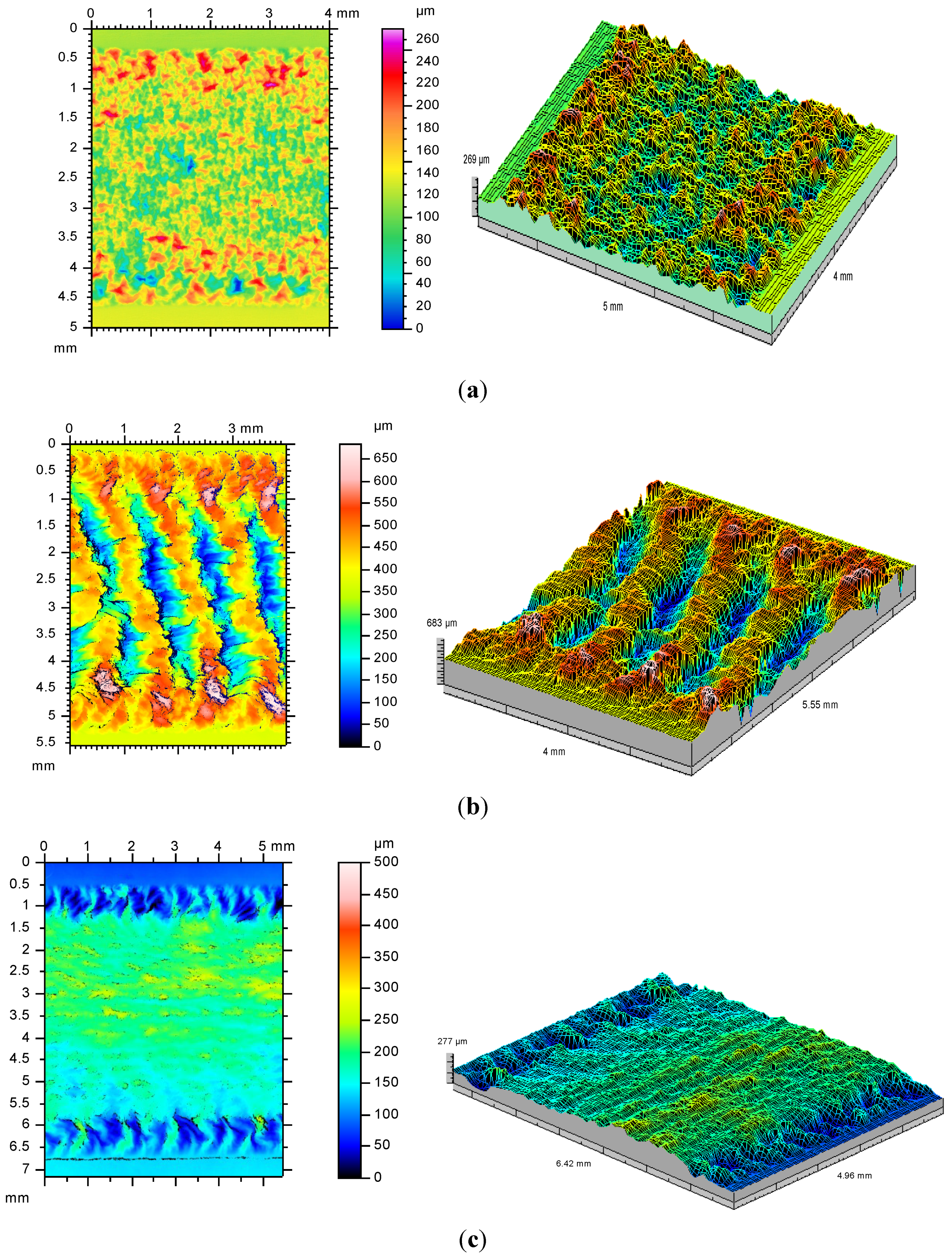
Figure 8.
2D and 3D topography of the surface layers produced on titanium alloy Ti6Al4V by HPDDL laser gas nitriding (Table 2 and Table 3); (a) sample No. P20; (b) sample No. P12; (c) sample No. P16.

Table 3.
Results of roughness measurements on the surface of titanium alloy Ti6Al4V specimen and on the nitrided surface layers (Table 2).
| Sample type | Roughness parameters, μm | |||||
|---|---|---|---|---|---|---|
| Rz | Rt | Ry | Sm | Ra | Rq | |
| Ti6Al4V as received | 4 ± 0.1 | 7 ± 0.18 | 6 ± 0.1 | 162 ± 3.9 | 0.4 ± 0.01 | 0.8 ± 0.01 |
| Sample No. P5 | 76 ± 1.3 | 98 ± 1.9 | 97 ± 2.1 | 491 ± 5.5 | 15.4 ± 0.4 | 18.8 ± 0.5 |
| Sample No. P8 | 53 ± 0.7 | 67 ± 1.6 | 62 ± 1.4 | 259 ± 4.3 | 9.4 ± 0.2 | 11.8 ± 0.3 |
| Sample No. P16 | 34 ± 0.9 | 42 ± 0.9 | 41 ± 0.8 | 229 ± 3.9 | 8.2 ± 0.19 | 10 ± 0.25 |
| Sample No. P20 | 136 ± 3.1 | 168 ± 3.7 | 157 ± 3.6 | 245 ± 4.1 | 25 ± 0.6 | 30.6 ± 0.9 |
Remarks: Rz, average distance between the highest peak and lowest valley in each sampling length; Rt, Maximum Height of the Profile; Ry, Maximum Height of the Profile; Sm, Mean Spacing of Profile Irregularities; Ra, arithmetic average of absolute values; Rq, Root Mean Square (RMS) Roughness.
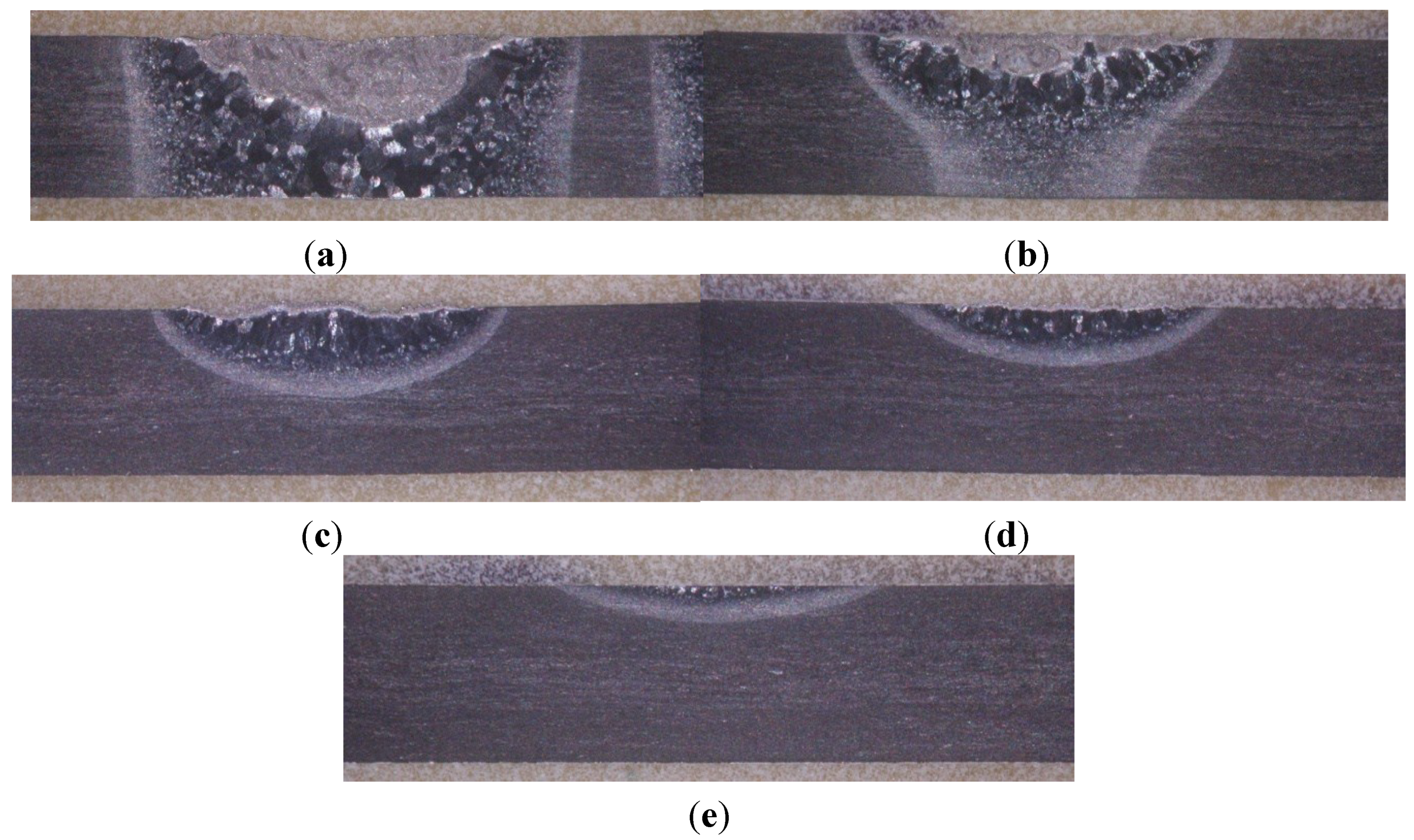
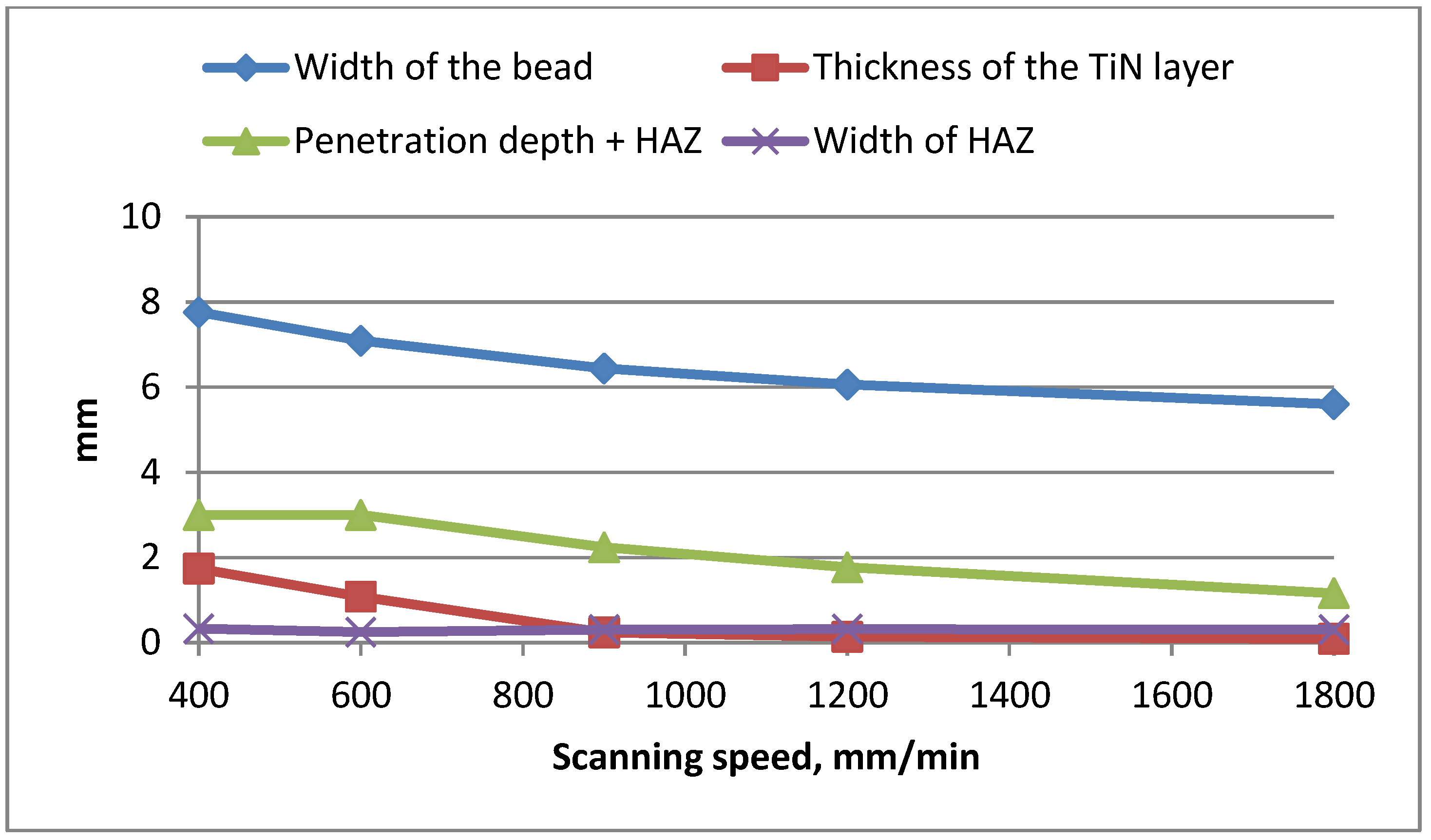
The shape, penetration depth, and width of the surface layers depend strongly on the parameters of laser gas nitriding with the HPDDL laser (Figure 9 and Figure 10, Table 2). The minimum thickness of the nitrided surface layer including the heat affected zone (HAZ), produced at the laser power 900 W, scanning speed 900 mm/min and thus heat input 60 J/mm is about 0.7 mm with the hard surface layer of TiN precipitations at about 0.05 mm (Table 2). While the maximum thickness of the TiN layer over 1.7 mm was produced at laser power 1800 W, scanning speed 400 mm/min and heat input 270 J/mm (Figure 7c and Figure 9a). The width of the surface layers in general correlated with the size of the HPDDL laser beam spot. The width of the diode laser beam spot is 6.8 mm, set perpendicularly to the scanning direction, therefore the width of the surface layers is in the range from 4.0 mm up to over 7.0 mm (Figure 10).
Figure 9.
A view of cross-sections of surface layers after laser gas nitriding of titanium alloy Ti6Al4V by the HPDDL laser (Table 2); (a) sample No. P16; (b) sample No. P4; (c) sample No. P12; (d) sample No. P20; (e) sample No. P22.
Figure 9.
A view of cross-sections of surface layers after laser gas nitriding of titanium alloy Ti6Al4V by the HPDDL laser (Table 2); (a) sample No. P16; (b) sample No. P4; (c) sample No. P12; (d) sample No. P20; (e) sample No. P22.

Figure 10.
Influence of the scanning speed on the geometry of nitrided surface layers produced at constant output laser power 1800 W (Table 2).
Figure 10.
Influence of the scanning speed on the geometry of nitrided surface layers produced at constant output laser power 1800 W (Table 2).

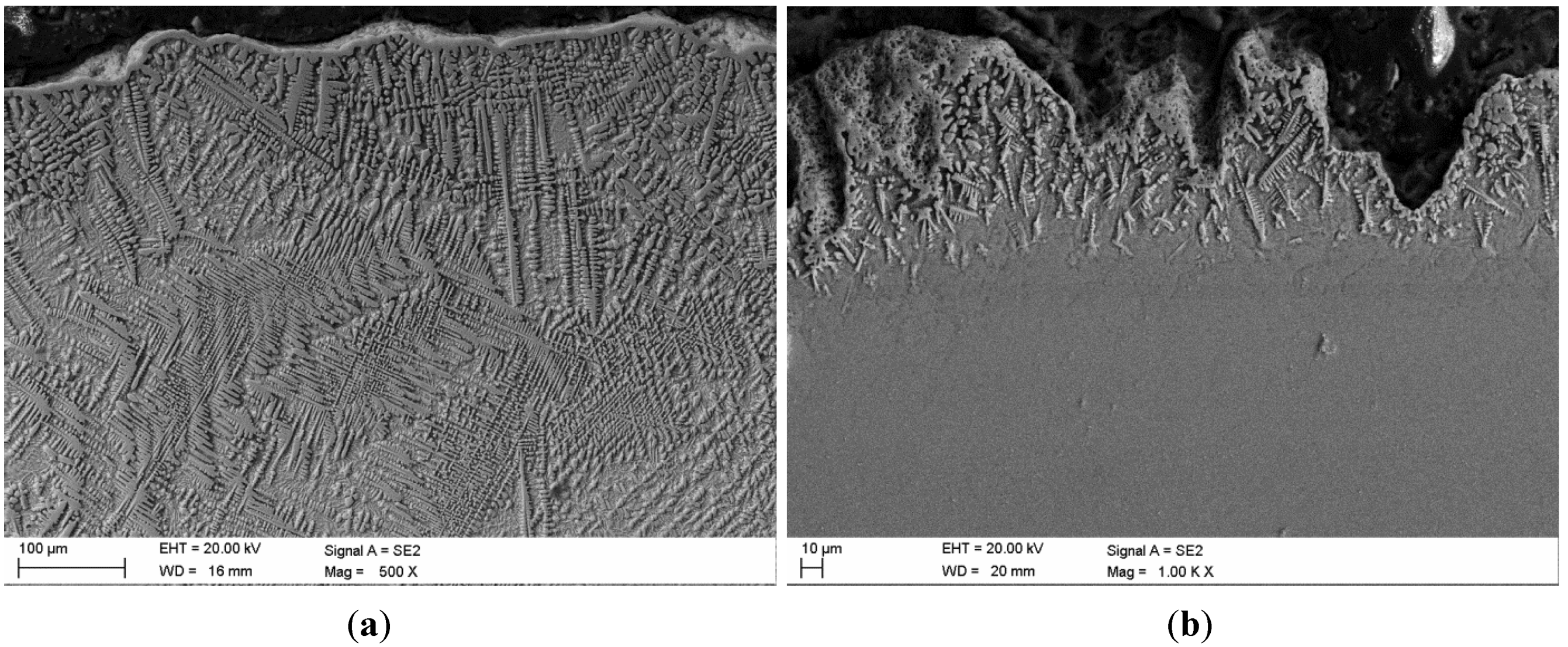
Figure 3a shows the microstructure of as-received 3.0 mm thick plate of the titanium alloy Ti6Al4V (base metal BM) comprised of two phases Tiα and Tiβ (shown in Figure 3b). Figure 11a shows scanning electron micrographs (SEM) of the surface layer No. 16, with the thicker layer of titanium nitrides up to 1.74 mm, produced at laser power 1800 W and scanning speed 400 mm/min, thus a heat input of 270 J/mm. In contrast Figure 11b shows SEM of the surface layer No. 20 with a thickness of the TiN layer of just about 0.14 mm, produced at laser power 1500 W and scanning speed 1500 mm/min, thus a heat input of just 60 J/mm (Table 2). In both cases a thin homogenous and consistent layer, about 10.0 μm thick, tightly covers the surface layers (Figure 11). From the homogenous layer on the top surface, dendritic precipitations grow into the bulk of the surface layer and all of the dendrites, in the near surface region are oriented perpendicularly to the top surface (Figure 11).
Figure 11.
(a) Scanning electron micrograph of the nitrided surface layer of sample No. P16 (Table 2) and (b) sample No. 20.
Figure 11.
(a) Scanning electron micrograph of the nitrided surface layer of sample No. P16 (Table 2) and (b) sample No. 20.

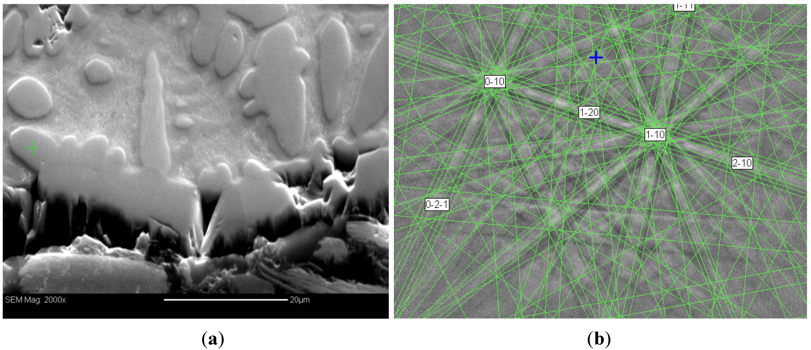
The electron backscatter diffraction (EBSD) analysis conducted directly below the top surface showed that the near surface region consists mainly of the titanium nitrides TiN embedded in the metal matrix of Tiα (Figure 12).
Figure 12.
(a) Scanning electron micrograph of the nitrided surface layer of sample No. P16 in the region just below the top surface (Table 2) and (b) results of EBSD analysis of the precipitations in the metal matrix. Phase name: TiN, composition: N (50 at.%), Ti (50 at.%).
Figure 12.
(a) Scanning electron micrograph of the nitrided surface layer of sample No. P16 in the region just below the top surface (Table 2) and (b) results of EBSD analysis of the precipitations in the metal matrix. Phase name: TiN, composition: N (50 at.%), Ti (50 at.%).

Microstructure study shows a good metallurgical bonding of the interface between nitrided layers rich in dendritic titanium nitrides and the substrate of titanium alloy Ti6Al4V, free of any internal imperfections or discontinuity such as transgranular and intergranular cracks, micro cracks, or porosity (Figure 11 and Figure 12).
The morphology and orientation of the titanium dendrites in the near surface region clearly indicate that the nucleation of dendrites takes place directly below the top surface of weld pool, near the liquid/gas boundary, as a result of nitrogen absorption from the gaseous atmosphere and subsequent increase of the nitrogen content in the liquid metal of a weld pool. The growth of titanium nitride dendrites (crystallization) proceeds into the liquid metal (weld pool), perpendicularly to the top surface.
When the laser beam as a heat source is being moved relative to the heated surface of titanium alloy, the heat transfer and thermal conditions are quite different compared to the steady state conditions during stationary heating [21]. Thus given the fact that the scanning speeds ranged from several to several tens mm/s and simultaneously the volume of a weld pool was not greater than 5–6 mm3, the time for nucleation and solidification of TiN dendrites was limited.
For example the volume of the weld pool of the surface layer produced at laser power 1800 W and scanning speed 400 mm/min (6.66 mm/s, Sample No. 16, Table 2) is about 5.5 mm3. It was estimated on the basis of the penetration depth profile (Figure 9a), the shape and the dimensions of the top surface of the solidified weld pool which is 6 mm wide and 0.7–1.5 mm long in the middle, as shown on the left side of Figure 7c. Having regard to the scanning speed 6.66 mm/s, the growth rate of the 250–300 µm long dendrites is about 1.3–2.8 mm·s−1.
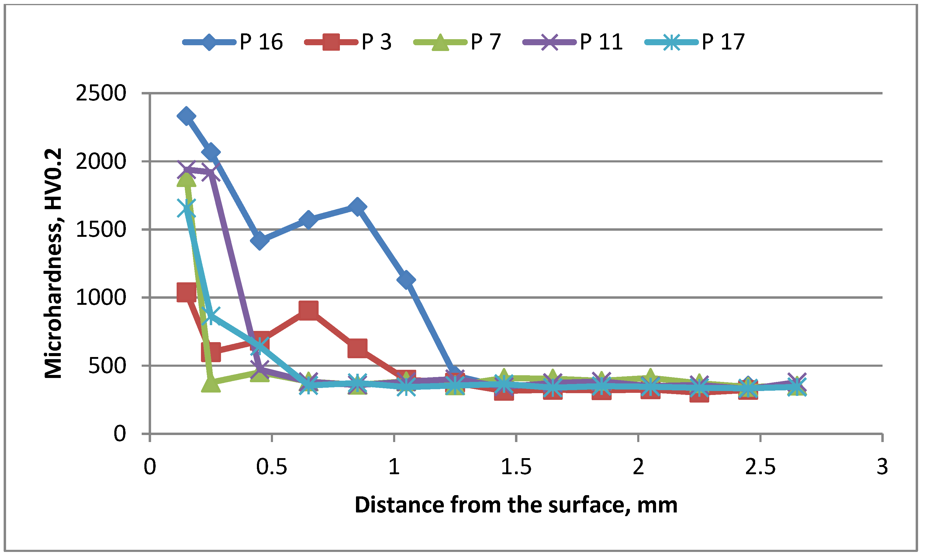
The microhardness measured on cross-sections of the nitrided surface layers is generally characterized as a gradient relationship as shown in Figure 13. The maximum value of microhardness reaches about 2400 HV0.2 in the case of the surface layer No. 16, with the highest penetration depth and greatest thickness of the hard layer of the titanium nitrides (Table 2). According to the various literature sources, the maximum microhardness of titanium nitride TiN may range from 1800–2100 HV or even up to 2400 HV. The maximum value was measured directly below the top surface, in a region where the density and percentage of titanium nitride precipitations is highest. Next the microhardness decreases gradually with the distance from the top surface down to the level of about 300 HV0.2 which is the microhardness of the Ti6Al4V titanium alloy (Figure 13). Additionally Figure 13 shows that the maximum values of microhardness measured on cross-sections of the individual surface layers depend directly on the penetration depth. This phenomenon may be related to the thickness of the titanium nitrides layer, as well as on the phase composition, especially on the percentage and density of hard titanium nitrides TiNx in the metal matrix (Figure 11 and Figure 12).
Figure 13.
Microhardness distribution on the cross-section of surface layers after laser gas nitriding of titanium alloy Ti6Al4V specimen 3.0 mm thick by HPDDL laser (Table 2).
Figure 13.
Microhardness distribution on the cross-section of surface layers after laser gas nitriding of titanium alloy Ti6Al4V specimen 3.0 mm thick by HPDDL laser (Table 2).

4. Conclusions
A high power direct diode laser with a rectangular laser beam spot, uniform energy distribution across the laser beam and emitting in the range of 808–940 nm was successfully applied for in situ production of composite surface layers, consisting of dendritic titanium nitrides precipitations TiN, embedded in the metal matrix of Tiα (Titanium Matrix Composite). Besides, a thin homogenous and consistent layer of titanium nitrides, about 10.0 μm thick, tightly covers the surface layers.
The composite surface layers produced by HPDDL laser nitriding of Ti6Al4V titanium alloy specimens in a pure nitrogen atmosphere, in the investigated range of processing parameters, were of high quality and free of any surface and internal defects such as cracks or porosity even in the case of very thick layers with very high hardness, often reported by many researchers who have used other types of lasers.
The topography and roughness of laser gas nitrided surface layers may be changed over a wide range from a very flat and even surface, through to a very rough, and up to uneven and humped, depending on the processing parameters. Similarly the thickness of laser gas nitrided surface layers may be changed over a wide range from about 0.1–0.15 mm up to very thick about 1.74 mm.
The heat input as a process parameter is not sufficient to identify and predict the properties of nitrided surface layers produced by the HPDDL laser. The nitrided surface layers produced at the same heat input but at different output laser power, different scanning speed, thus different time of laser beam interaction and also different power density, have significantly different surface topography, roughness, and thus different morphology. Therefore the properties of the nitrided surface layers are directly dependent on the power density of the HPDDL laser beam and the time of laser beam interaction on the treated surface of the titanium alloy.
Acknowledgments
I am grateful to A. Grabowski, K. Gołombek and A. Iwaniak for substantive and experimental support. This work was partially supported by the Center of Innovation and Technology Transfer of Silesian University of Technology under the project 05/TWIP/BP/2013.
Conflicts of Interest
The author declares no conflict of interest.
References
- Katayama, S.; Matsunawa, A.; Morimoto, A.; Ishimoto, S.; Arata, Y. Surface hardening of titanium by laser nitriding. In Proceedings of the ICALEO’83, Los Angeles, CA, USA, 14–17 November 1983; pp. 127–134.
- Kurc-Lisiecka, A.; Ozgowicz, W.; Ratuszek, W.; Kowalska, J. Analysis of deformation texture in AISI 304 steel sheets. Sol. St. Phenom. 2013, 203–204, 105–110. [Google Scholar] [CrossRef]
- Opiela, M.; Grajcar, A. Hot deformation behavior and softening kinetics of Ti-V-B microalloyed steels. Arch. Civ. Mech. Eng. 2012, 12, 327–333. [Google Scholar] [CrossRef]
- Biswas, A.; Li, L.; Chatterjee, U.K.; Manna, I.; Majumdar, J.D. Diode laser assisted surface nitriding of Ti-6Al-4V: Properties of the nitrided surface. Metall. Mater. Trans. A 2009, 40A, 3031–3037. [Google Scholar] [CrossRef]
- Biswas, A.; Li, L.; Maity, T.K.; Chatterjee, U.K.; Mordike, B.L.; Manna, I.; Majumdar, J.D. Laser surface treatment of Ti-6Al-4V for bio-implant application. Lasers Eng. 2007, 17, 59–73. [Google Scholar]
- Biswas, A.; Li, L.; Chatterjee, U.K.; Manna, I.; Pabi, S.K.; Majumdar, J.D. Mechanical and electrochemical properties of laser surface nitrided Ti–6Al–4V. Scr. Mater. 2008, 59, 239–242. [Google Scholar] [CrossRef]
- Man, H.C.; Bai, M.; Cheng, F.T. Laser diffusion nitriding of Ti–6Al–4V for improving hardness and wear resistance. Appl. Surf. Sci. 2011, 258, 436–441. [Google Scholar] [CrossRef]
- Majumdar, J.D. Laser gas alloying of Ti-6Al-4V. Phys. Proc. 2011, 12, 472–477. [Google Scholar] [CrossRef]
- Burdzik, R.; Konieczny, Ł.; Stanik, Z.; Folega, P.; Smalcerz, A.; Lisiecki, A. Analysis of impact of chosen parameters on the wear of camshaft. Arch. Metall. Mater. 2014, 59, 961–967. [Google Scholar]
- Kusiński, J.; Kac, S.; Kopia, A.; Radziszewska, A.; Rozmus-Górnikowska, M.; Major, B.; Major, L.; Marczak, J.; Lisiecki, A. Laser modification of the materials surface layer—A review paper. Bull. Pol. Acad. Sci. 2012, 60, 711–728. [Google Scholar]
- Santos, E.; Morita, M.; Shiomi, M.; Osakada, K.; Takahashi, M. Laser gas nitriding of pure titanium using CW and pulsed Nd:YAG lasers. Surf. Coat. Technol. 2006, 201, 1635–1642. [Google Scholar] [CrossRef]
- Perez, M.G.; Harlan, N.R.; Zapirain, F.; Zubiri, F. Laser nitriding of an intermetallic TiAl alloy with a diode laser. Surf. Coat. Technol. 2006, 200, 5152–5159. [Google Scholar] [CrossRef]
- Rességuier, T.; Loison, D.; Dragon, A.; Lescoute, E. Laser driven compression to investigate shock-induced melting of metals. Metals 2014, 4, 490–502. [Google Scholar] [CrossRef]
- Węgrzyn, T. The Classification of Metal Weld Deposits in Terms of the Amount of Nitrogen. Available online: http://www.isope.org/publications/proceedings/ISOPE/ISOPE%202000/pdffiles/papers/Vol4/022.pdf (accessed on 29 December 2014).
- Thomann, A.L.; Sicard, E.; Boulmer-Leborgne, C.; Vivien, C.; Hermann, J.; Andreazza-Vignolle, C.; Andreazza, P.; Meneau, C. Surface nitriding of titanium and aluminum by laser-induced plasma. Surf. Coat. Technol. 1997, 97, 448–452. [Google Scholar] [CrossRef]
- Lisiecki, A. Mechanism of laser surface modification of the Ti-6Al-4V alloy in nitrogen atmosphere using a high power diode laser. Adv. Mater. Res. 2014, 1036, 411–416. [Google Scholar] [CrossRef]
- Yilbas, B.S.; Karatas, C.; Uslan, I.; Keles, O.; Usta, I.Y.; Ahsan, M. CO2 laser gas assisted nitriding of Ti–6Al–4V alloy. Appl. Surf. Sci. 2006, 252, 8557–8865. [Google Scholar] [CrossRef]
- Garcia, I.; Damborenea, J. Corrosion properties of TiN prepared by laser gas alloying of Ti and Ti5Al3V. Corros. Sci. 1998, 40, 1411–1419. [Google Scholar] [CrossRef]
- Gołębiewski, M.; Kruzel, G.; Major, R.; Mróz, W.; Wierzchoń, T.; Ebner, R.; Major, B. Morphology of titanium nitride produced using glow discharge nitriding, laser remelting and pulsed laser deposition. Mater. Chem. Phys. 2003, 81, 315–318. [Google Scholar] [CrossRef]
- Ohtsu, N.; Kodama, K.; Kitagawa, K.; Wagatsuma, K. Comparison of surface films formed on titanium by pulsed Nd:YAG laser irradiation at different powers and wavelengths in nitrogen atmosphere. Appl. Surf. Sci. 2010, 256, 4522–4526. [Google Scholar] [CrossRef]
- Lisiecki, A. Experimental and numerical study of heat conditions during diode laser gas nitriding of titanium alloy. Adv. Mater. Res. 2014, 1036, 320–325. [Google Scholar] [CrossRef]
- Janicki, D. High power diode laser cladding of wear resistant metal matrix composite coatings. Sol. State Phenom. 2013, 199, 587–592. [Google Scholar] [CrossRef]
- Casati, R.; Vedani, M. Metal matrix composites reinforced by nano-particles—a review. Metals 2014, 4, 65–83. [Google Scholar] [CrossRef]
- Xue, L.; Islam, M.; Koul, A.K.; Bibby, M.; Wallace, W. Laser gas nitriding of Ti-6Al-4V part 1: Optimization of the process. Adv. Perf. Mater. 1997, 4, 25–47. [Google Scholar] [CrossRef]
- Carpene, E.; Schaaf, P.; Han, M.; Lieb, K.P.; Shinn, M. Reactive surface processing by irradiating with excimer laser, Nd:YAG laser, free electron laser and Ti:sapphire laser in nitrogen atmosphere. Appl. Surf. Sci. 2002, 186, 195–199. [Google Scholar] [CrossRef]
- Bodzenta, J.; Kaźmierczak-Bałata, A.; Wokulska, K.; Kucytowski, J.; Szperlich, P.; Łukasiewicz, T.; Hofman, B. Analysis of influence of Yb concentration on thermal, elastic, optical and lattice parameters in YAG single crystal. J. Alloy Compd. 2009, 473, 245–249. [Google Scholar] [CrossRef]
© 2015 by the authors; licensee MDPI, Basel, Switzerland. This article is an open access article distributed under the terms and conditions of the Creative Commons Attribution license (http://creativecommons.org/licenses/by/4.0/).
Share and Cite
MDPI and ACS Style
Lisiecki, A. Titanium Matrix Composite Ti/TiN Produced by Diode Laser Gas Nitriding. Metals 2015, 5, 54-69. https://doi.org/10.3390/met5010054
AMA Style
Lisiecki A. Titanium Matrix Composite Ti/TiN Produced by Diode Laser Gas Nitriding. Metals. 2015; 5(1):54-69. https://doi.org/10.3390/met5010054
Chicago/Turabian StyleLisiecki, Aleksander. 2015. "Titanium Matrix Composite Ti/TiN Produced by Diode Laser Gas Nitriding" Metals 5, no. 1: 54-69. https://doi.org/10.3390/met5010054