
Water Impingement Erosion of Deep-Rolled Ti64


 ,
,
Abstract
:
1. Introduction

2. Experimental Section
2.1. Materials

2.2. Deep-Rolling Treatment

| Level Parameters | High Level (+) | Low Level (−) |
|---|---|---|
| Spindle velocity (rpm) | 150 | 75 |
| DR feed (mm/r) | 0.20 | 0.06 |
| Number of passes | 3 | 1 |
| DR pressure (bar) | 200 | 100 |
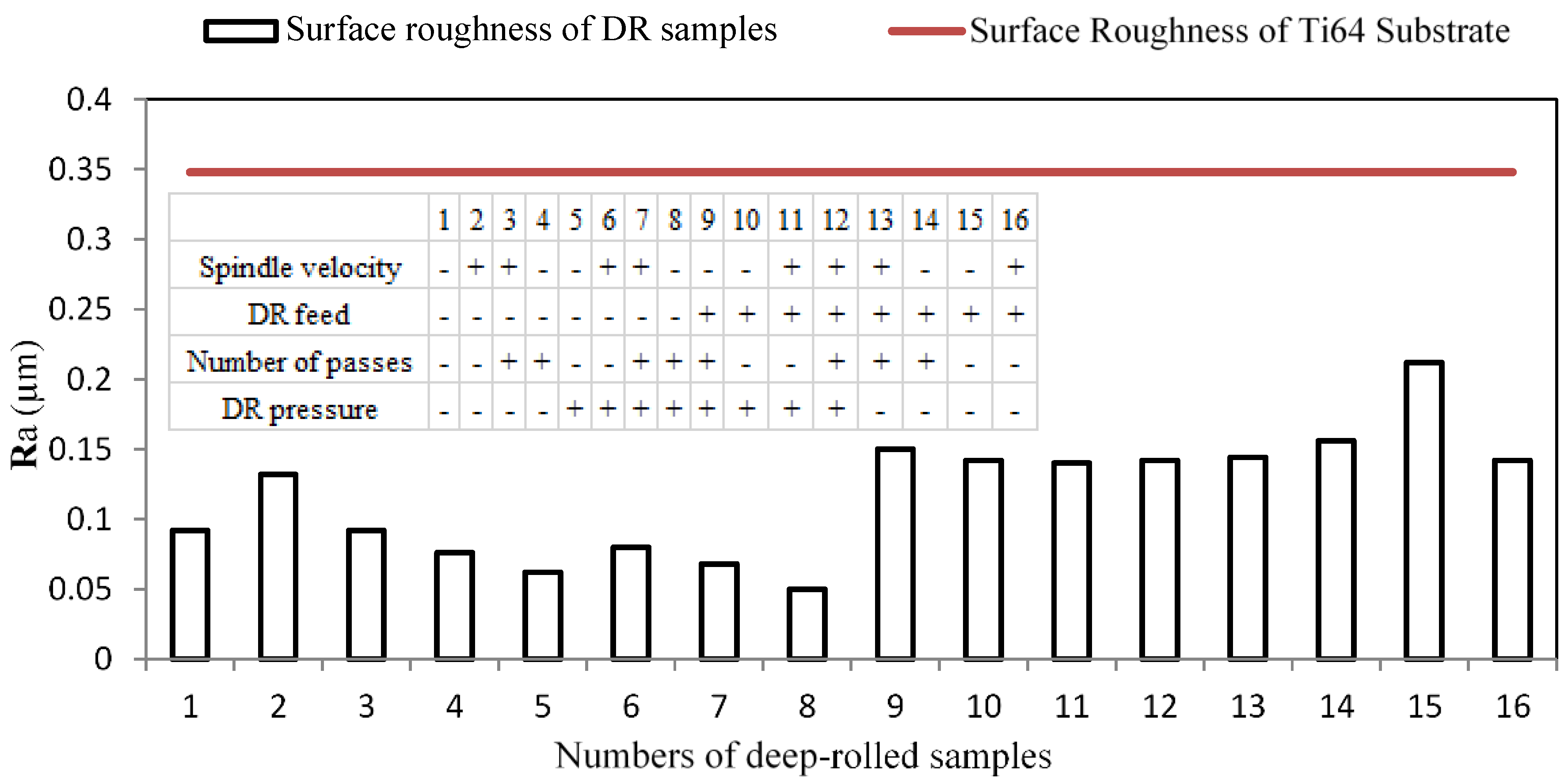
| Parameters | 1 | 2 | 3 | 4 | 5 | 6 | 7 | 8 | 9 | 10 | 11 | 12 | 13 | 14 | 15 | 16 |
|---|---|---|---|---|---|---|---|---|---|---|---|---|---|---|---|---|
| Spindle velocity | − | + | + | − | − | + | + | − | − | − | + | + | + | − | − | + |
| DRfeed | − | − | − | − | − | − | − | − | + | + | + | + | + | + | + | + |
| Number of passes | − | − | + | + | − | − | + | + | + | − | − | + | + | + | − | − |
| DRpressure | − | − | − | − | + | + | + | + | + | + | + | + | − | − | − | − |
2.3. Characterization of DR-Treated Ti64
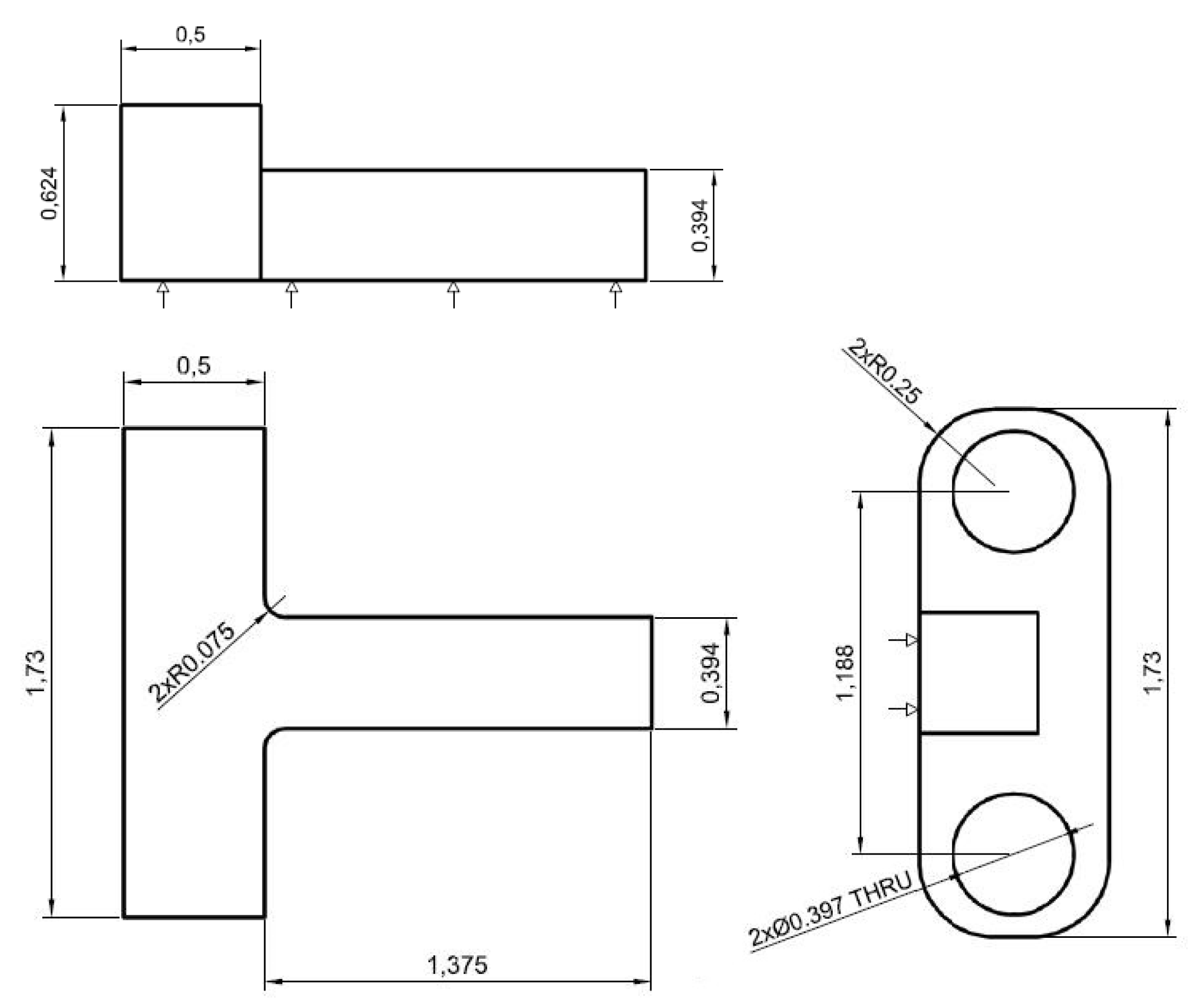
2.4. Liquid Impingement Erosion Test


3. Results and Discussion
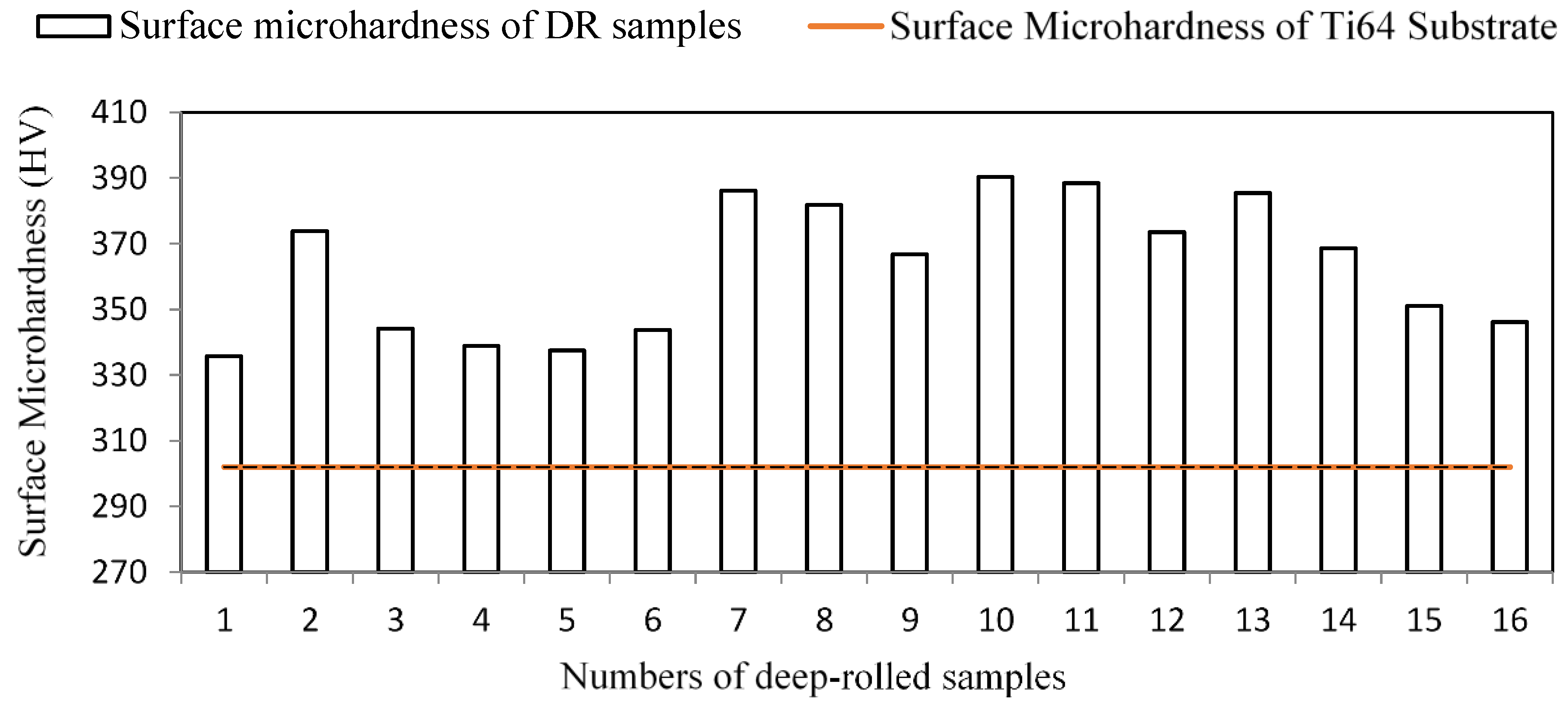
3.1. Surface Roughness and Microhardness


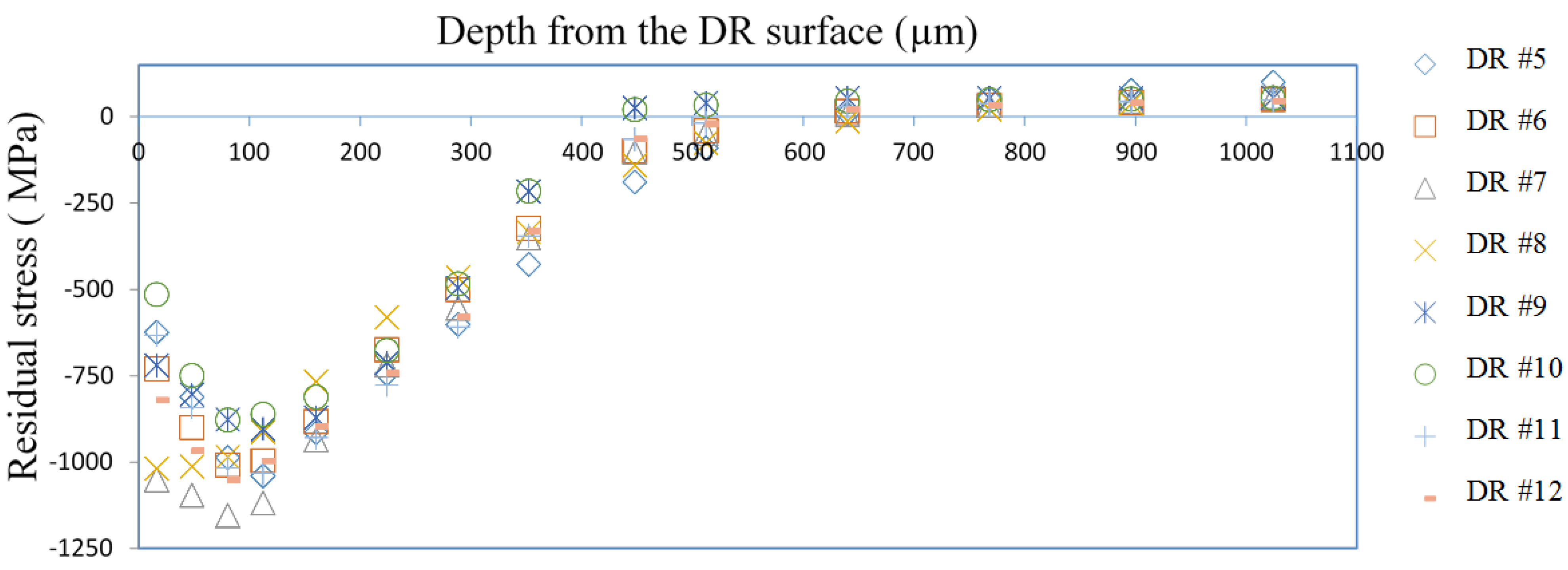
3.2. Residual Stress Profiles


| Sample No. | DR #7 | DR #8 | Reference Ti64 |
|---|---|---|---|
| Spindle speed (rpm) | 150 | 75 | - |
| Feed rate (mm/rev) | 0.06 | 0.06 | - |
| No. of passes | 3 | 3 | - |
| Pressure (Bar) | 200 | 200 | - |
| Surface Microhardness (HV) | 381.06 | 381.78 | 302.0 |
| Surface Roughness (μm) | 0.068 | 0.050 | 0.082 |
| Residual stresses (MPa) | −1154 | −1018 | Stress free |
| Depth of residual stresses (μm) | 640 | 640 | 0 |
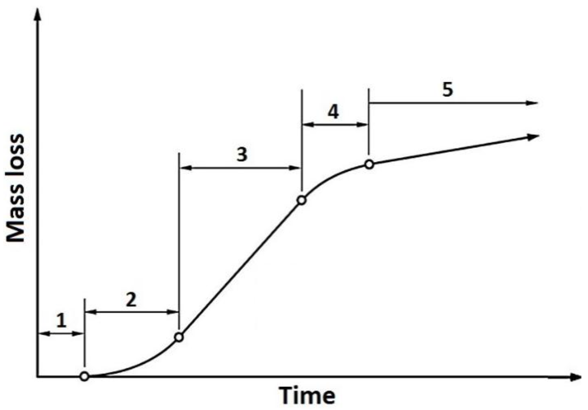
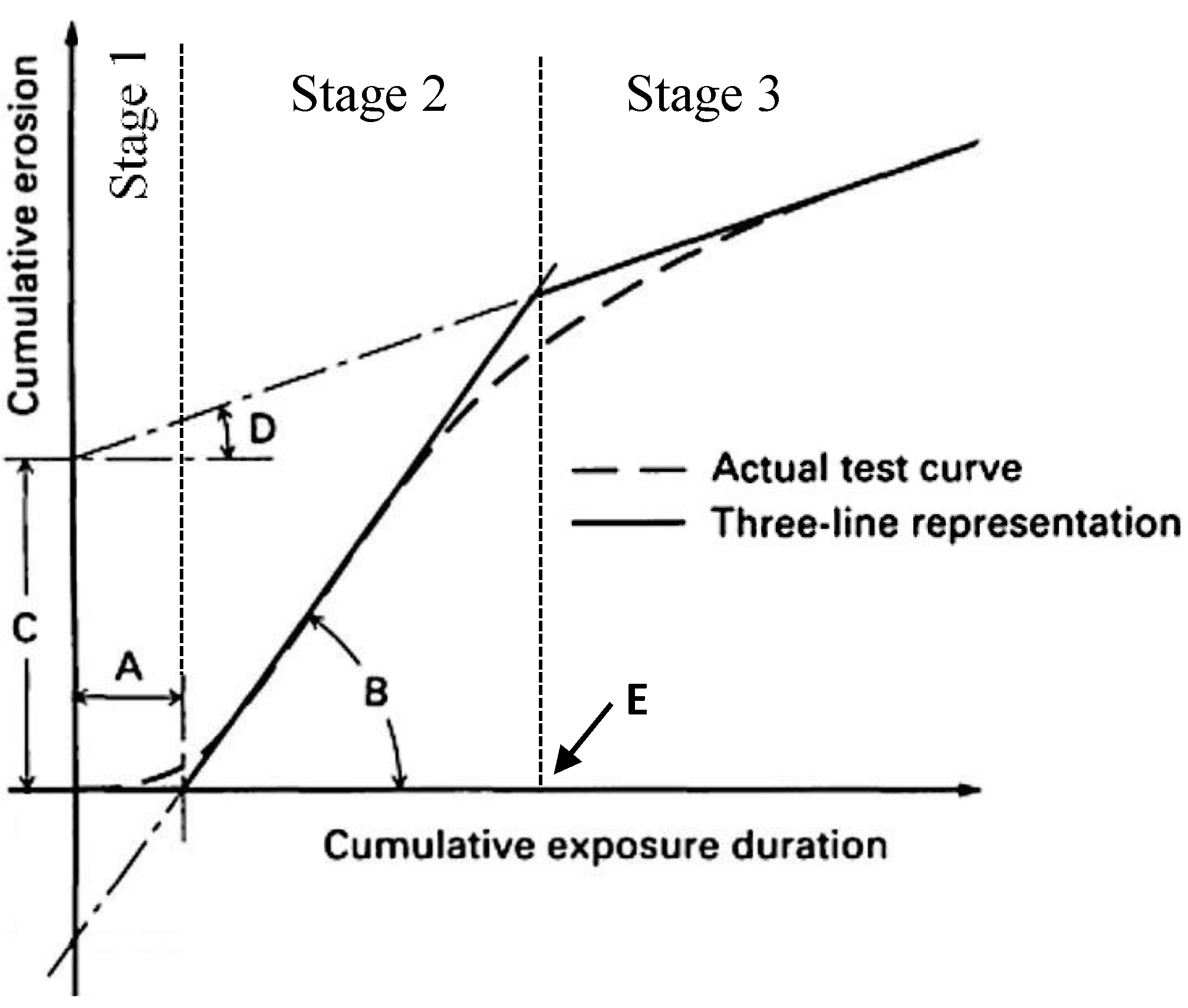
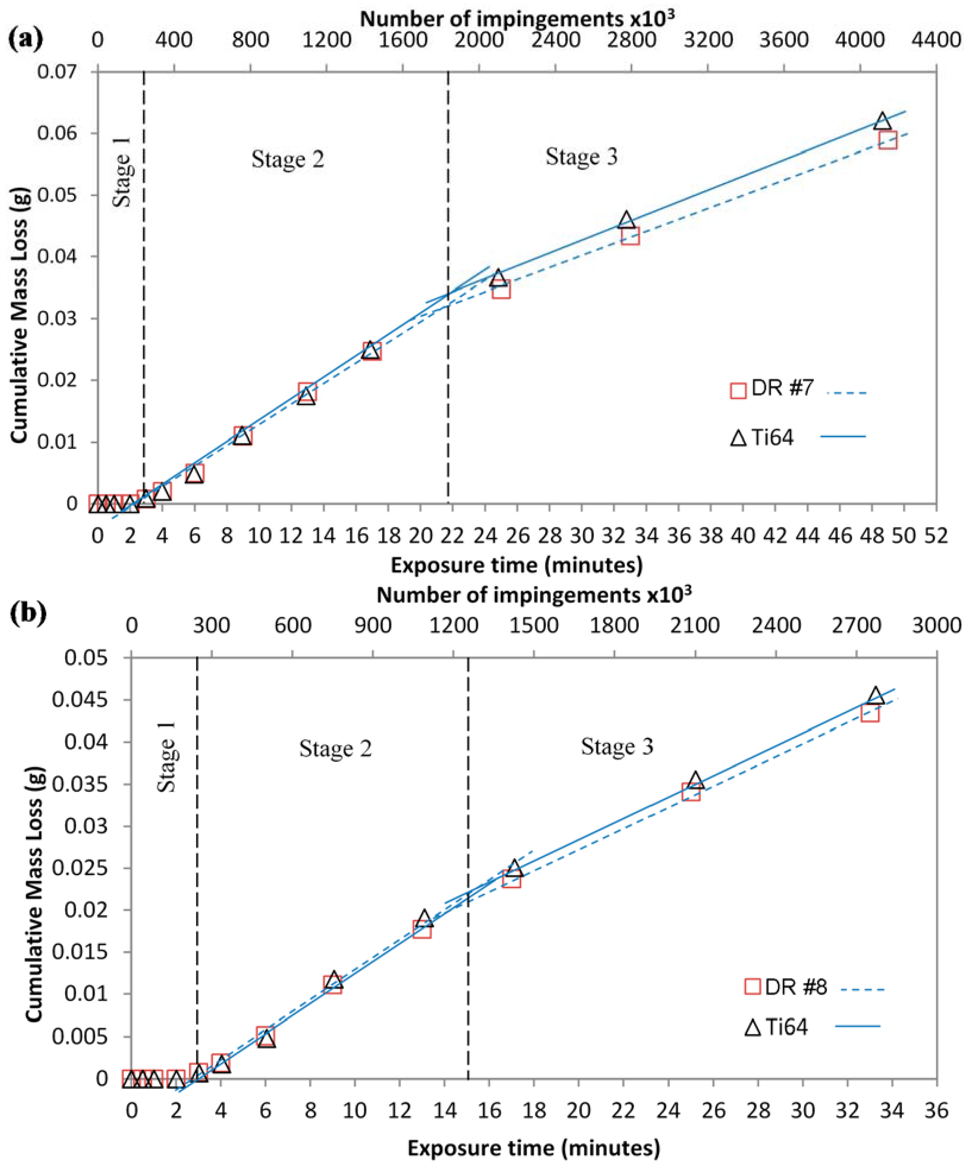
3.3. LIE Tests

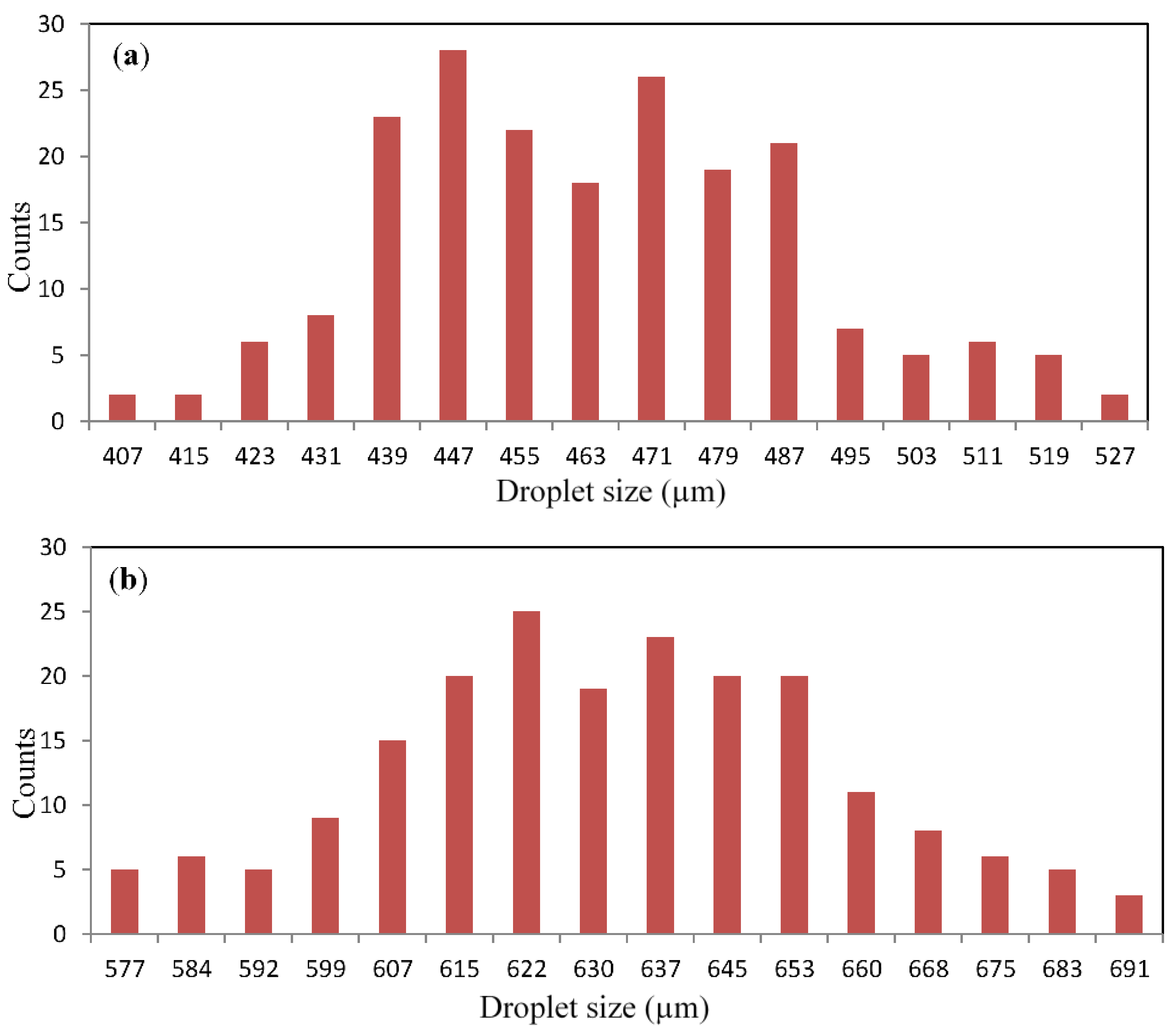
| Test No. | Impacting Speed (m/s) | Droplet Size (μm) | Samples | Incubation Period—A (min) | Maximum Erosion Rate—B (g/min) | End Time of the Second Stage of LIE—E (min) |
|---|---|---|---|---|---|---|
| 1 | 250 | 460 | DR #7 | 30 | 0.0002 | 94 |
| Ti64 | 29 | 0.0002 | 96 | |||
| 2 | 350 | 460 | DR #7 | 3 | 0.0018 | 21 |
| Ti64 | 3 | 0.0018 | 21 | |||
| DR #8 | 3 | 0.0018 | 15 | |||
| Ti64 | 3 | 0.0018 | 15 | |||
| 3 | 250 | 630 | DR #7 | 24 | 0.0002 | 121 |
| Ti64 | 28 | 0.0002 | 131 | |||
| DR #8 | 26 | 0.0002 | 88 | |||
| Ti64 | 25 | 0.0002 | 94 | |||
| 4 | 350 | 630 | DR #7 | 1.5 | 0.0026 | 9 |
| Ti64 | 1.5 | 0.0026 | 9 | |||
| DR #8 | 1.5 | 0.0025 | 7 | |||
| Ti64 | 1.7 | 0.0025 | 7 |


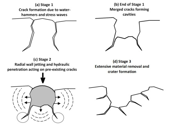
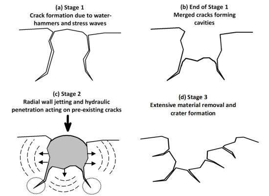
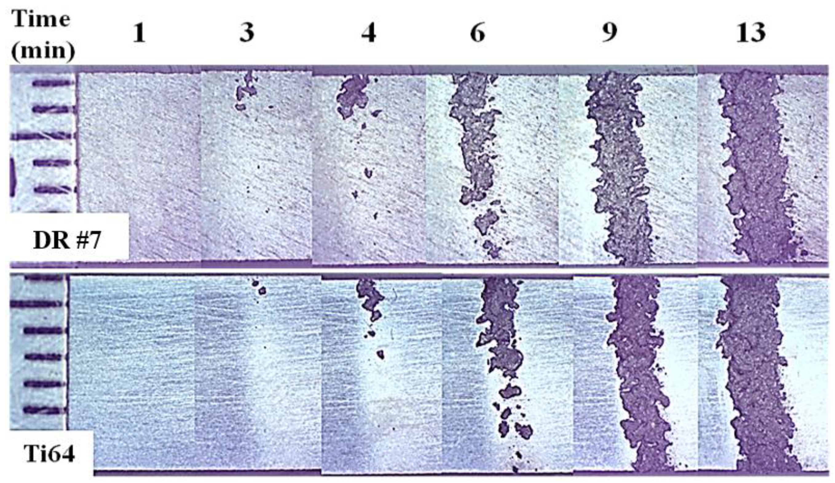
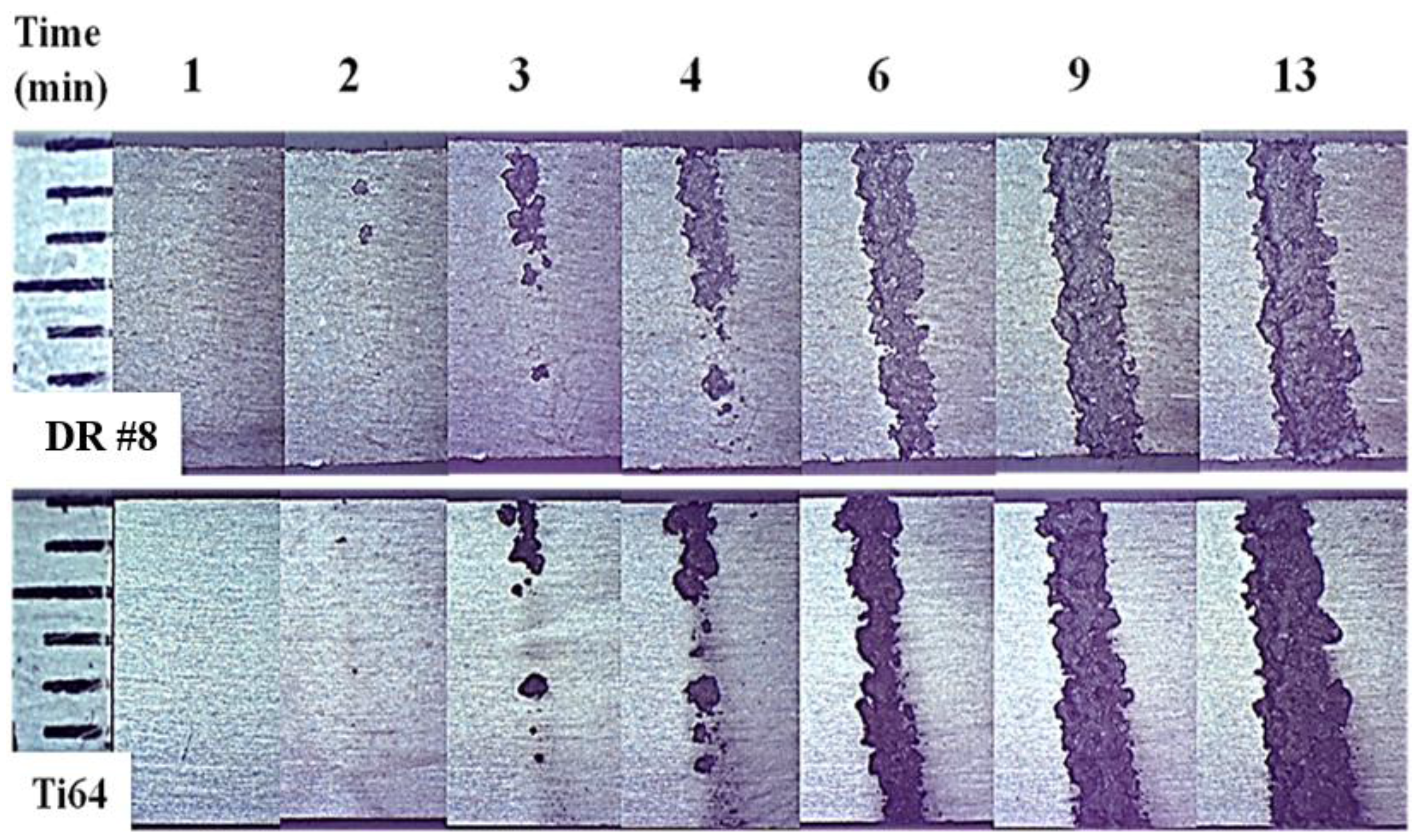
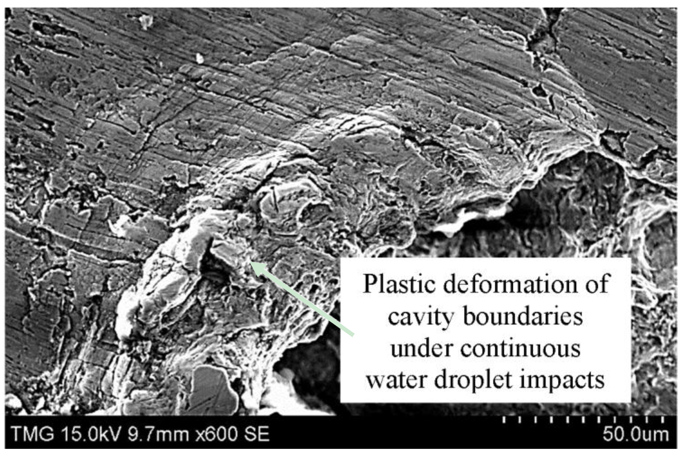
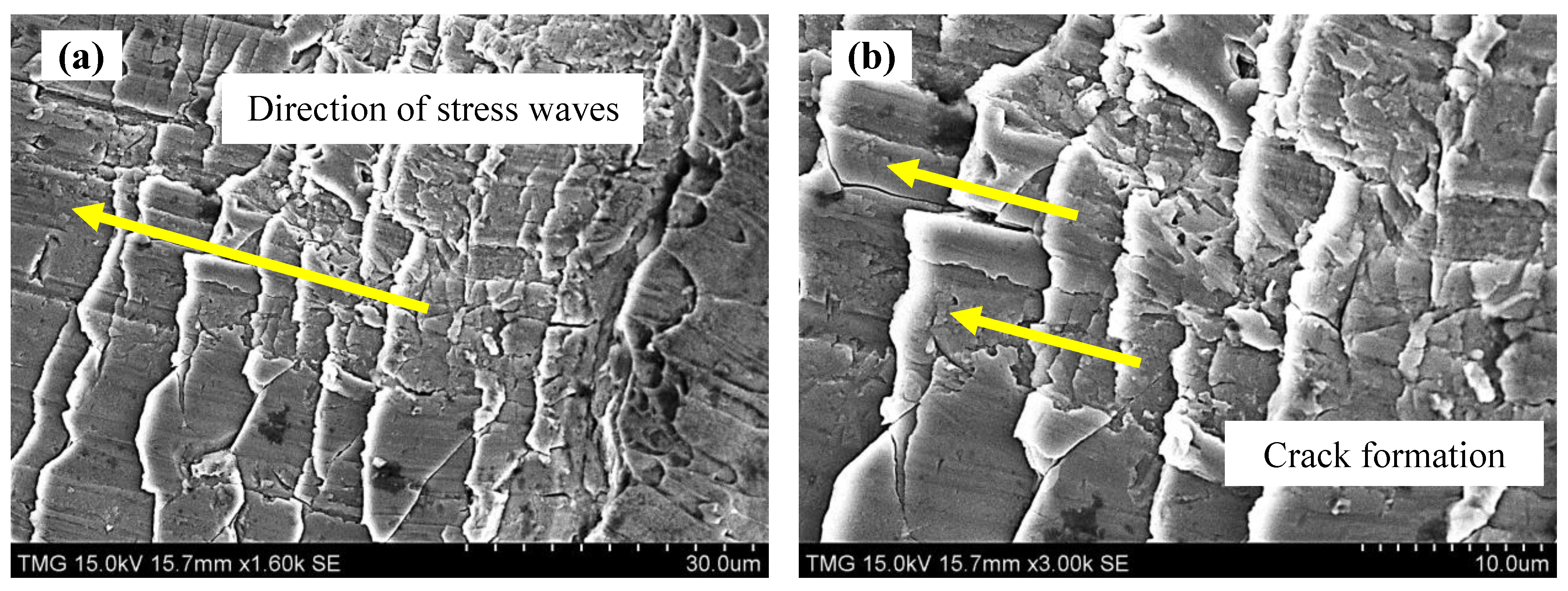
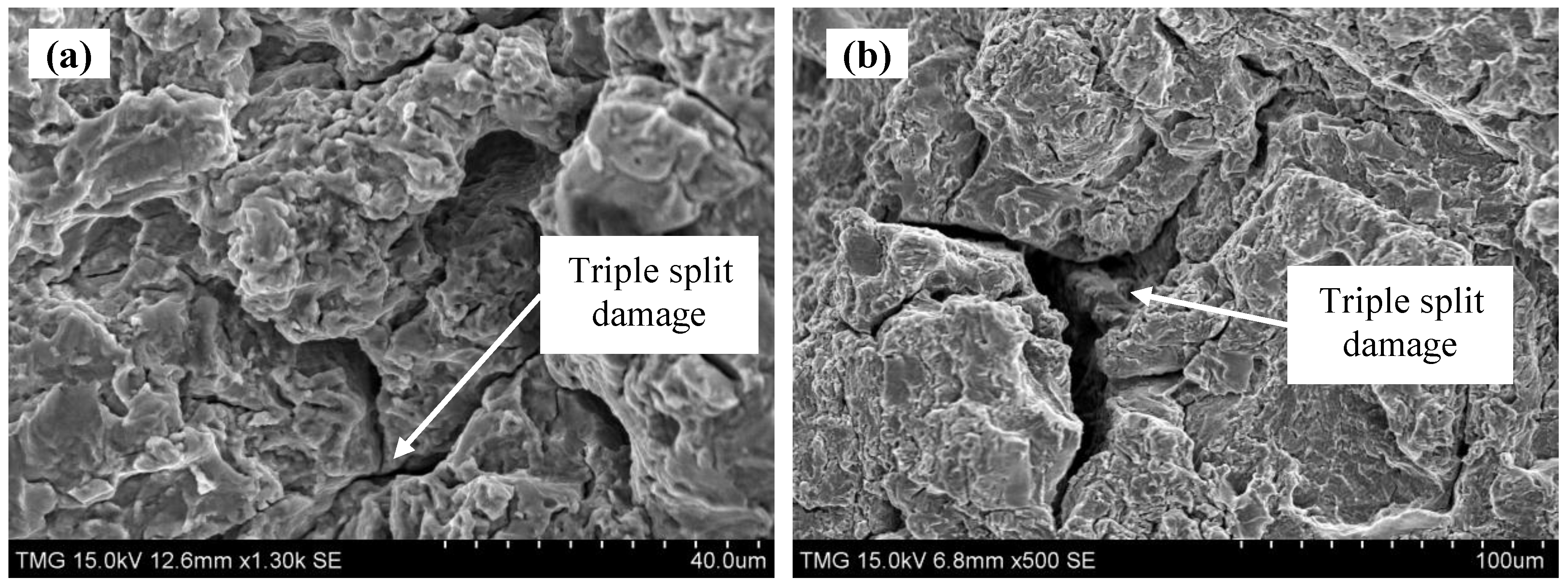
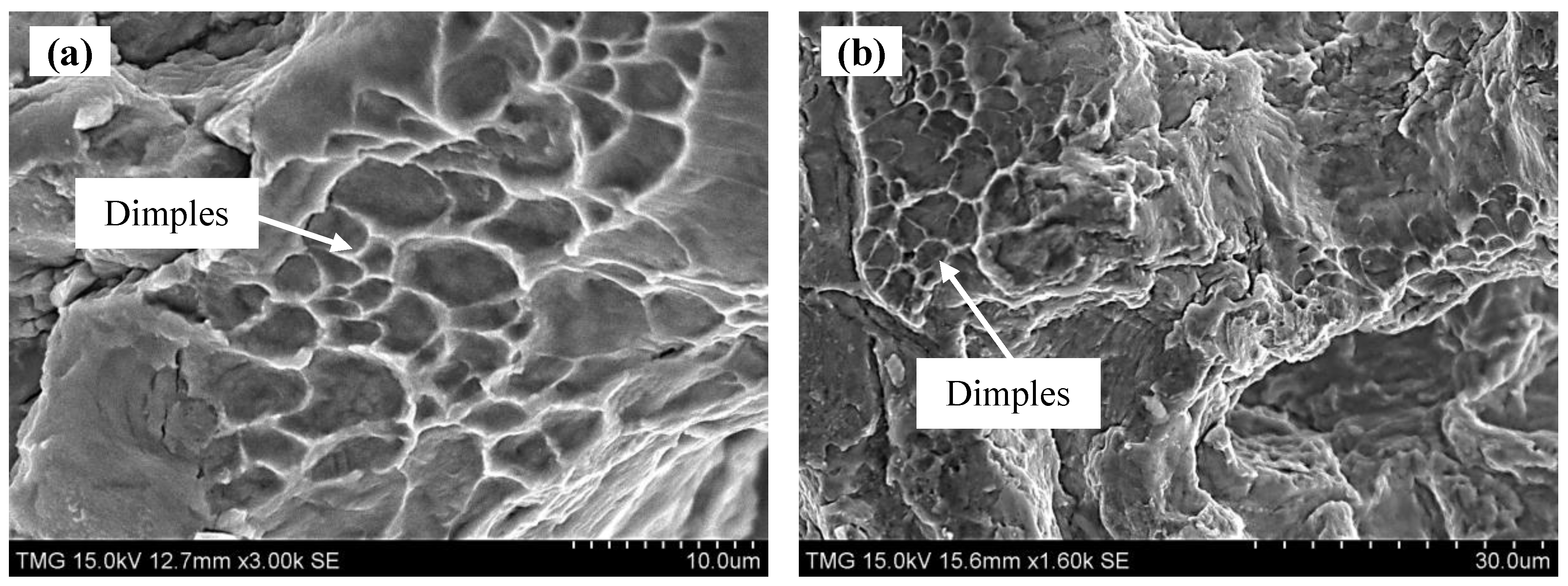
3.4. LIE Material Removal Mechanisms


3.5. Damage Behaviors of Ti64 before and after DR Treatment
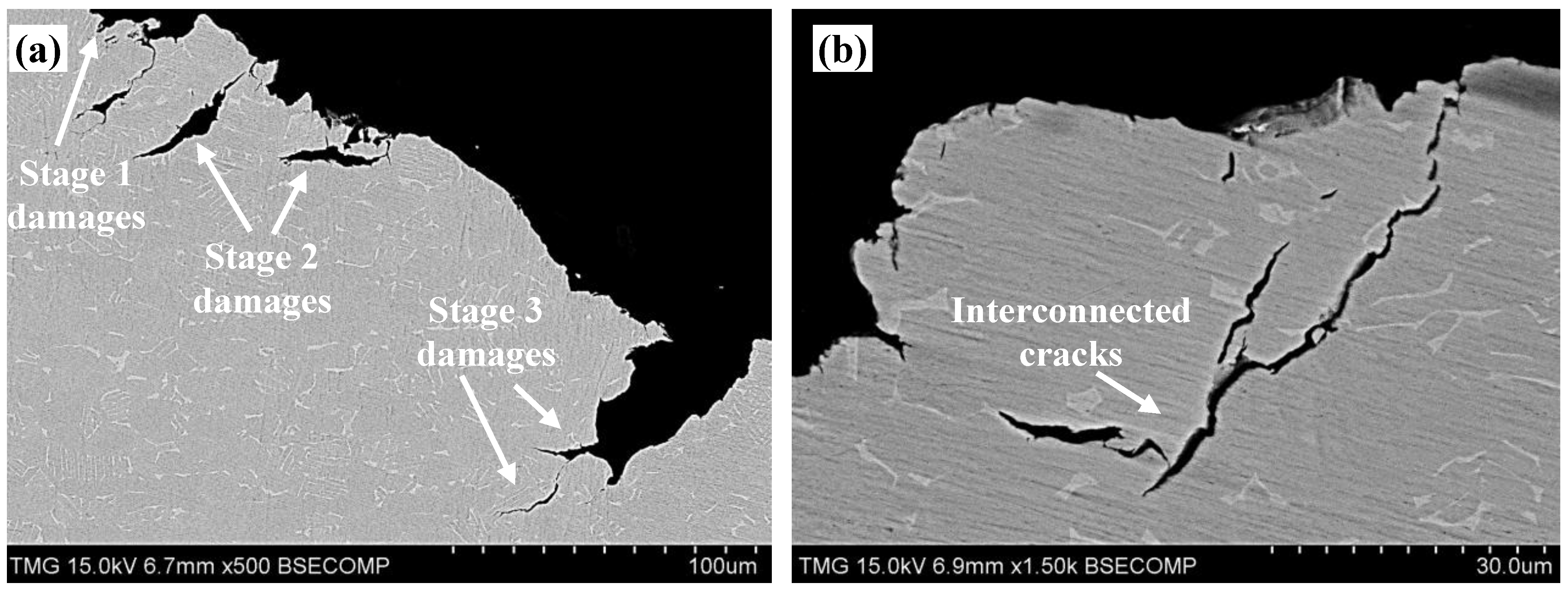
3.5.1. Stage 1 of the LIE Test
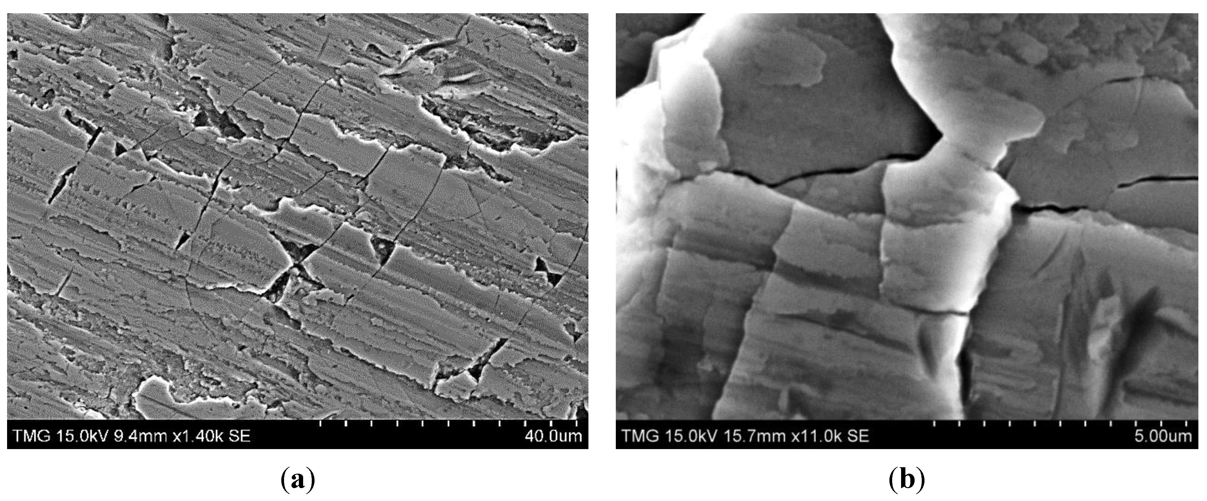
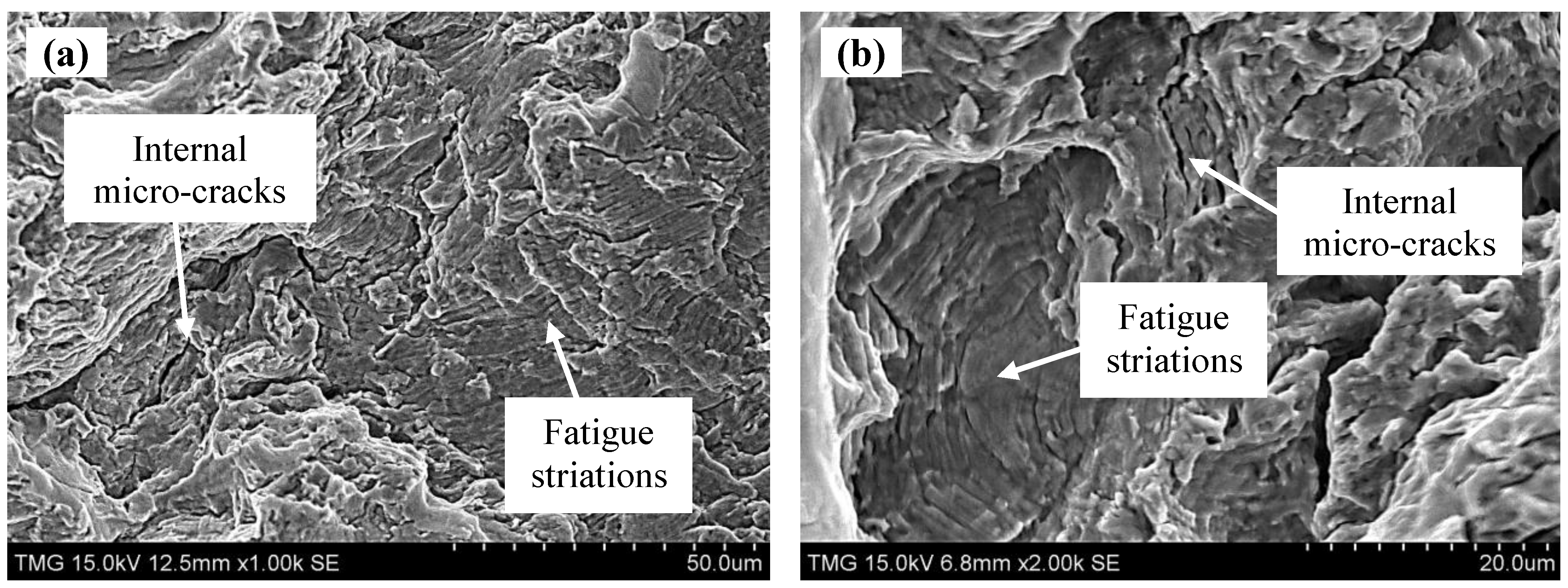
3.5.2. Stage 2 of the LIE Test


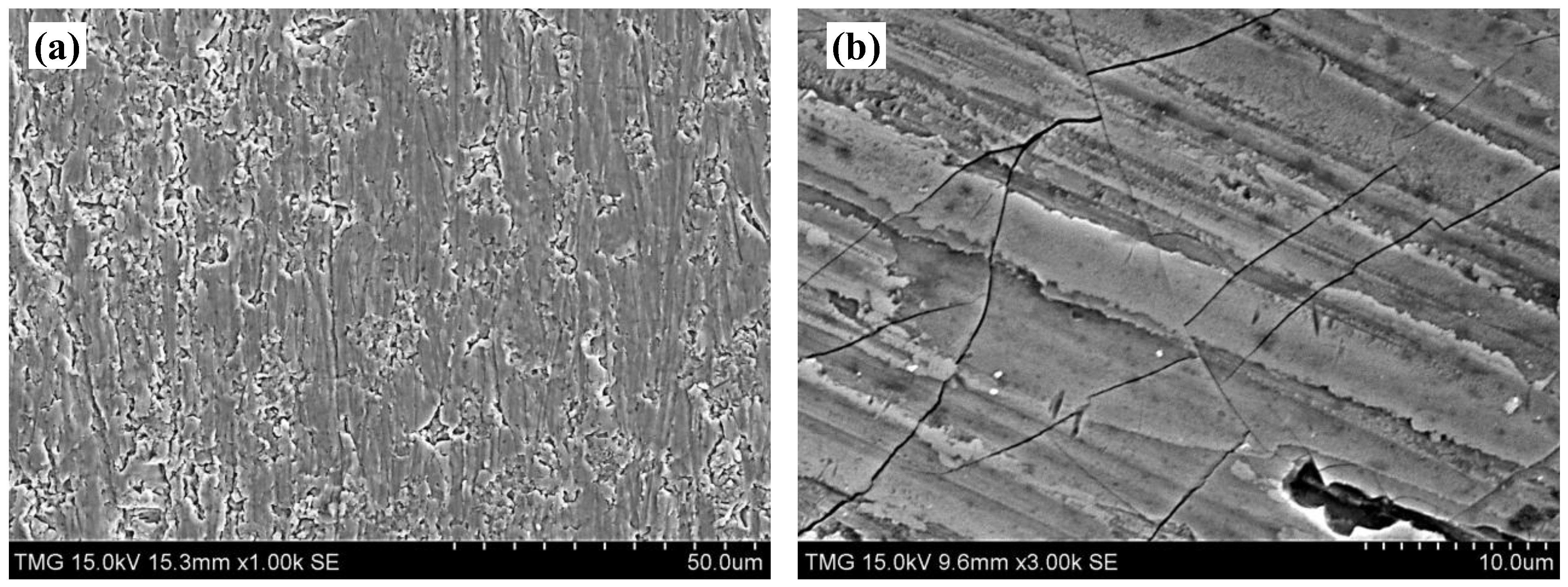
3.5.3. Stage 3 of LIE Test


4. Conclusions
Acknowledgments
Author Contributions
Conflicts of Interest
References
- Meher-Homji, C.B.; Mee, T.R. Gas turbine power augmentation by fogging of inlet air. In Proceedings of the 28th Turbomachinery Symposium, College Station, TX, USA, September 1999; pp. 93–114.
- Turbine inlet cooling: Technology overview. Available online: http://www.turbineinletcooling.org/ (accessed on 10 June 2015).
- MDS coating technologies corporation. Available online: http://www.mdscoating.com/technology/index.html (accessed on 10 June 2015).
- Heymann, F. Liquid Impingement Erosion; ASM International: Materials Park, OH, USA, 1992; Volume 18. [Google Scholar]
- Rao, P.V.; Buckley, D.H. Empirical Relations for Cavitation and Liquid Impingement Erosion Processes; NASA Technical Paper 2339; NASA: Washington, DC, USA, 1984. [Google Scholar]
- Jolliffe, K.H. The development of erosion damage in metals by repeated liquid droplet impacts. Proc. A 1968. [Google Scholar] [CrossRef]
- Meng, P.; Geskin, E.S.; Leu, M.C.; Li, F.; Tismeneskiy, L. An Analytical and experimental study of cleaning with moving waterjets. J. Manuf. Sci. Eng. 1998, 120, 580–589. [Google Scholar] [CrossRef]
- Thomas, G.P.; Brunton, J.H. Drop impingement erosion of metals. Proc. A 1972. [Google Scholar] [CrossRef]
- Xiong, J.; Koshizuka, S.; Sakai, M.; Ohshima, H. Investigation on droplet impingement erosion during steam generator tube failure accident. Nucl. Eng. Des. 2012, 249, 132–139. [Google Scholar] [CrossRef]
- Robinson, J.; Reed, R. Water droplet erosion of laser surface treated Ti6Al4V. Wear 1995, 187, 360–367. [Google Scholar] [CrossRef]
- Oka, Y.I.; Mihara, S.; Miyata, H. Effective parameters for erosion caused by water droplet impingement and applications to surface treatment technology. Wear 2007, 263, 386–394. [Google Scholar] [CrossRef]
- Zhuang, W.; Wicks, B. Mechanical surface treatment technologies for gas turbine engine components. J. Eng. Gas Turbine Power 2003, 125, 1021. [Google Scholar] [CrossRef]
- Nalla, R.; Altenberger, I.; Noster, U.; Liu, G.; Scholtes, B.; Ritchie, R. On the influence of mechanical surface treatments—Deep rolling and laser shock peening—On the fatigue behavior of Ti6Al4V at ambient and elevated temperatures. Mater. Sci. Eng. A 2003, 355, 216–230. [Google Scholar] [CrossRef]
- Gray, H.; Wagner, L.; Lütjering, G. Influence of shot peening induced surface roughness, residual macrostresses and dislocation density on the elevated temperature HCF-properties of Ti-alloys. In Proceedings of the 3rd International Conference on Shot Peening (ICSP3), Garmisch-Partenkirchen, Germany, September 1987; pp. 447–457.
- Ludian, T.; Wagner, L. Mechanical surface treatments for improving fatigue behaviour in titanium alloys. Adv. Mater. Sci. 2008, 8, 44–52. [Google Scholar]
- Prevéy, P.; Hornbach, D.; Ravindranath, R. Application of low plasticity burnishing to improve damage tolerance of a Ti-6Al-4V first stage fan blade. In Proceedings of the 44th AIAA/ASME/ASCE/AHS Structures, Structural Dynamics & Materials Conference, Norfolk, VA, USA, 7–10 April 2003; pp. 1–9.
- Prevéy, P.; Shepard, M.; Smith, P. The effect of low plasticity burnishing (LPB) on the HCF performance and FOD resistance of Ti-6Al-4V. In Proceedings of the 6th National Turbine Engine High Cycle Fatigue (HCF) Conference, Jacksonville, FL, USA, 5–8 March 2001; pp. 1–10.
- Prevéy, P.; Hornbach, D.; Cammett, J.; Ravindranath, R. Damage tolerance improvement of Ti-6-4 fan blades with low plasticity burnishing. In Proceedings of the 6th Joint FAA/DoD/NASA Aging Aircraft Conference, San Francisco, CA, USA, 16–19 September 2002; pp. 1–9.
- Prevéy, P.; Hornbach, D.; Jacobs, T.; Ravindranath, R. Improved damage tolerance in titanium alloy fan blades with low plasticity burnishing. In Proceedings of the International Surface Engineering Conference, Columbus, OH, USA, 7–10 October 2002; pp. 1–9.
- Jayaraman, N.; Hornbach, D.; Prevéy, P.; Langer, K.; Hoover, J.; van Hoogan, S.; Shepard, M. Mitigation of fatigue and pre-cracking damage in aircraft structures through low plasticity burnishing (LPB). In Proceedings of the AISP, Palm Spring, CA, USA, 4–6 December 2007; pp. 1–11.
- Prevéy, P.; Jayaraman, N.; Ravindranath, R. Fatigue life extension of steam turbine alloys using low plasticity burnishing (LPB). In Proceedings of the ASME Turbo Expo 2010: Power for Land, Sea, and Air, Glasgow, UK, 14–18 June 2010; Volume 7, pp. 2277–2287.
- Zhang, P.; Lindemann, J. Effect of roller burnishing on the high cycle fatigue performance of the high-strength wrought magnesium alloy AZ80. Scr. Mater. 2005, 52, 1011–1015. [Google Scholar] [CrossRef]
- Ibrahim, A.A. An investigation into ball burnishing process of carbon steel on a lathe. In Proceedings of Al-Azhar Engineering Tenth International Conference, Cairo, Egypt, 24–26 December 2008.
- Altenberger, I. Alternative Mechanical Surface Treatments—Microstructure, Residual Stresses and Fatigue Behaviour. In Shot Peening; Wagner, L., Ed.; Wiley-VCH: Garmisch-Partenkirchen, Germany, 2003; pp. 421–434. [Google Scholar]
- Prevéy, P.; Jayaraman, N.; Cammett, J. Overview of low plasticity burnishing for mitigation of fatigue damage mechanisms. In Proceedings of the ICSP 9, Fatigue and Fracture of Steels, Paris, France, 6–9 September 2005; pp. 1–6.
- Scheel, J.E.; Hornbach, D.J.; Prevey, P.S. Mitigation of stress corrosion cracking in nuclear weldments using low plasticity burnishing. In Proceedings of the 16th International Conference on Nuclear Engineering, ICONE16, ASME, Orlando, FL, USA, 11–15 May 2008; pp. 649–656.
- Kong, M.C.; Axinte, D.; Voice, W. Aspects of material removal mechanism in plain waterjet milling on gamma titanium aluminide. J. Mater. Process. Tech. 2010, 210, 573–584. [Google Scholar] [CrossRef]
- Hammitt, F.; Heymann, F. Liquid-Erosion Failures; ASM International: Materials Park, OH, USA, 1986; pp. 164–171. [Google Scholar]
- Adler, W.F. The Mechanics of Liquid Impact; Academic Press Inc.: London, UK, 1979. [Google Scholar]
- Kirols, H.S.; Kevorkov, D.; Uihlein, A.; Medraj, M. The effect of initial surface roughness on water droplet erosion behavior. Wear submitted for pubulication. 2015. [Google Scholar]
- ASTM E837-01. In Standard Test Method for Determining Residual Stresses by the Hole-Drilling Strain-Gage Method; ASTM International: West Conshohocken, PA, USA, 2001.
- Schwarz, T.; Kockelmann, H.; Tietz, H.-D.; Böhm, S. Eigenspannungen und Verzug Durch Wärmeeinwirkung (German); Wiley-VCH: Weinheim, Germany, 1999. [Google Scholar]
- Wenzelburger, M.; López, D.; Gadow, R. Methods and application of residual stress analysis on thermally sprayed coatings and layer composites. Surf. Coat. Technol. 2006, 201, 1995–2001. [Google Scholar] [CrossRef]
- Residual stress and strain measurement (XRD and hole drilling). Available online: http://www.npl.co.uk/science-technology/engineered-materials/services/residual-stress-and-strain-measurement (accessed on 10 June 2015).
- ASTM G73-10. In Standard Test Method for Liquid Impingement Erosion Using Rotating Apparatus; ASTM International: West Conshohocken, PA, USA, 2010.
- Maawad, E.; Brokmeier, H.-G.; Wagner, L.; Sano, Y.; Genzel, C. Investigation on the surface and near-surface characteristics of Ti–2.5Cu after various mechanical surface treatments. Surf. Coat. Technol 2011, 205, 3644–3650. [Google Scholar] [CrossRef]
- Haag, M. Untersuchungen zur schädigungsentwicklung an dampfturbinenwerkstoffen infolge von wassertropfenerosion. Ph.D. Thesis, Technische Universität Kaiserslautern, Kaiserslautern, Germany, 2012. [Google Scholar]
- Luiset, B.; Sanchette, F.; Billard, A.; Schuster, D. Mechanisms of stainless steels erosion by water droplets. Wear 2013, 303, 459–464. [Google Scholar] [CrossRef]
- Huang, L.; Folkes, J.; Kinnell, P.; Shipway, P.H. Mechanisms of damage initiation in a titanium alloy subjected to water droplet impact during ultra-high pressure plain waterjet erosion. J. Mater. Process. Tech. 2012, 212, 1906–1915. [Google Scholar] [CrossRef]
© 2015 by the authors; licensee MDPI, Basel, Switzerland. This article is an open access article distributed under the terms and conditions of the Creative Commons Attribution license (http://creativecommons.org/licenses/by/4.0/).
Share and Cite
Ma, D.; Mostafa, A.; Kevorkov, D.; Jedrzejowski, P.; Pugh, M.; Medraj, M. Water Impingement Erosion of Deep-Rolled Ti64. Metals 2015, 5, 1462-1486. https://doi.org/10.3390/met5031462
Ma D, Mostafa A, Kevorkov D, Jedrzejowski P, Pugh M, Medraj M. Water Impingement Erosion of Deep-Rolled Ti64. Metals. 2015; 5(3):1462-1486. https://doi.org/10.3390/met5031462
Chicago/Turabian StyleMa, Dina, Ahmad Mostafa, Dmytro Kevorkov, Pawel Jedrzejowski, Martin Pugh, and Mamoun Medraj. 2015. "Water Impingement Erosion of Deep-Rolled Ti64" Metals 5, no. 3: 1462-1486. https://doi.org/10.3390/met5031462