Article

Sputtering Power Effects on Growth and Mechanical Properties of Cr2AlC MAX Phase Coatings

1
Chair of Physical Metallurgy and Materials Technology, Brandenburg Technical University, Cottbus 03046, Germany
2
Department of Material Science, Welding and Strength of Material, Wroclaw University of Science and Technology, Wrocław 50370, Poland
3
University of South Florida, Tampa, FL 33620, USA
*
Author to whom correspondence should be addressed.
Metals 2016, 6(11), 265; https://doi.org/10.3390/met6110265
Submission received: 13 September 2016 / Revised: 21 October 2016 / Accepted: 25 October 2016 / Published: 5 November 2016
(This article belongs to the Special Issue Ni- and Co-Based Superalloys and Their Coatings)

Abstract

:
Coating growth and mechanical properties of nanolamellar Cr2AlC coatings at various sputtering power were investigated in the present study. Cr2AlC coating was deposited on the IN 718 superalloy and (100) Si wafers by DC magnetron sputtering at different sputtering powers. The structure and properties were characterized using X-ray diffraction (XRD), scanning electron microscopy (SEM), transmission electron microscopy (TEM) and nanoindentation. It was found that coatings had columnar structure with nanocrystalline substructure. Deposition rate increased with the sputtering power. XRD results showed the presence of the Cr2AlC MAX phase, intermetallic AlCr2 and Cr7C3 carbide phases, along with the change in preferential coating growth orientation. TEM observations confirmed the occurrence of these phases, and the SAED patterns demonstrated significant texture of the coatings. Hardness values were measured in the range between 11–14 GPa, showing a slight increase with the sputtering power.

1. Introduction

MAX phase is a group of compounds, which provides a unique combination of metallic and ceramic properties due to the presence of M-A metallic and M-X ceramic bonds. They are nanolamellas with Mn+1AXn (n is 1, 2, or 3) chemical formula, where M is an early transition metal, A is an A-group element from the periodic table and X is either carbon or nitrogen [1]. These compounds are known for their low density [1], high stiffness [2,3], superior thermal shock resistance [1,4], damage tolerance [5,6], self-healing behavior [7,8], significant electrical conductivity [4,9], and erosion [10], oxidation [11,12,13,14,15,16] and hot corrosion resistance [6,17]. Moreover, Mn+1AXn phases have been identified as promising candidates for hydrogen storage applications [18] along with other materials [19,20].
Reports on deposition of the MAX phases as thin films using chemical vapor deposition (CVD) [21] and physical vapor deposition (PVD) [2,22] methods can be found in the literature. Palmquist et al. [23] were the first to deposit the MAX-phase thin coating (Ti3SiC2) by physical vapor deposition. Since then, more than 70 compounds have been fabricated through physical vapor deposition and other methods [22,24]. In recent years, ternary carbide Cr2AlC has attracted much attention because of its excellent high-temperature oxidation and hot corrosion resistance [14,25,26,27], due to preferential formation of continuous protective Al2O3 oxide at high temperatures [15]. Moreover, a small difference in thermal expansion coefficients between Cr2AlC and Ni-based alloys makes them along with Cr2(Alx,Ge1−x)C, potential protective film candidates at high temperature [28,29].
Cr2AlC films can be produced either by sputtering from elemental targets [30,31,32] or compound targets [10,33]. Literature indicates advantages of lower deposition temperatures for Cr2AlC [33] in contrast to other MAX phase coatings, like Ti2AlC and Ti3AlC2 [34], which is promising for deposition on heat-sensitive substrates, such as steel. Coating growth depends on a number of process parameters, including substrate bias, deposition temperature, chamber pressure, etc. Sputtering power as a process parameter influences the coating growth, electric resistance, surface roughness [35], mechanical and tribological properties [36]. Past research proved that high metal ionization results from increased sputtering power, eventually affecting coating growth. Extremely high sputtering power could also lead to increased energy of the incoming metal ions, leading to erosion of the already deposited film [37]. Hence, optimization of the sputtering power can lead to better coating design with control of mechanical and chemical properties. However, the effects of sputtering power on coating growth and mechanical properties of Cr2AlC coatings have not been systemically studied yet. X-ray diffraction (XRD) was utilized to support the arguments provided for the coating growth. Furthermore, correlations between mechanical properties and sputtering power were discussed.

2. Materials and Methods

Cr2AlC coatings were deposited using a compound target (Cr 50%, Al 25%, and C 25 at. %, 99.9% purity) on IN 718 superalloy and (100) silicon wafers in direct current magnetron sputtering (DCMS) mode. The coating deposition was performed in a CC800/9 industrial coater from CemeCon AG (Würselen, Germany). Prior to deposition, Inconel 718 substrates were wet mirror polished and then cleaned in acetone. The target size was 88 mm × 500 mm and sputtering was performed in a static mode. The distance between the target and the substrate was set at 70 mm. The coating process consisted of a heating phase, followed by argon etching for cleaning organic/foreign particles from the surface and eventually the coating phase. Further details of the deposition process parameters are given in Table 1.
Scanning electron microscopy (SEM, TESCAN Mira, Prague, Czech Republic) was used to investigate the film growth on (100) Si wafers. IN 718 substrates were used for all other investigations. For a global phase determination, D8 Discover X-ray diffractometer (Bruker AXS, Karlsruhe, Germany) with Cu Kα radiation (λ = 0.1546 nm) with an operating voltage of 40 KV and 40 mA current was used. Grazing incidence X-ray diffraction (GIXRD) method with an incident beam angle of 9°, step width of 0.05°, and a 2θ range between 10° and 70° was used for the measurements. Absorption of the incident beam within the Cr2AlC coating was calculated by means of the AbsorbDX software (Bruker AXS, Karlsruhe, Germany). Moreover, film growth kinetics was also analyzed by transmission electron microscopy (TEM). Hitachi H-800 TEM (Hitachi High-Technologies Corp., Tokyo, Japan) was operated at 150 kV accelerating voltage. Software developed in the Electron Microscopy Lab at Wroclaw University of Technology (Wroclaw, Poland) was used for local phase analysis, based on electron diffraction patterns. Nanoindentation tests were performed using the UNAT nanoindenter (ASMEC GmbH, Radeberg, Germany) with a Berkovich indenter tip in order to determine mechanical properties (hardness and elastic modulus) of the coatings. By means of the quasi continuous stiffness method (QCSM), the correlation between mechanical properties and penetration depth was determined. A load of 25 mN guaranteed that the penetration depth did not exceed 1/10th of the coating thickness [38] whereas, the load–displacement curves were analyzed using the Oliver Pharr method [39].

3. Results and Discussion

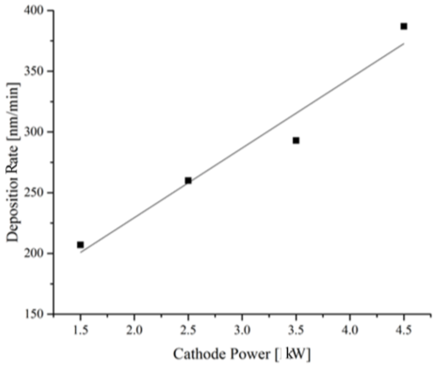
3.1. Coating Deposition Rate

The deposition rate of the Cr2AlC coatings using DCMS shows almost linear relationship with the sputtering power. Deposition rate increase of almost 100% can be seen with the sputtering power increase from 1.5 kW to 4.5 kW in Figure 1.
This deposition rate increase with the sputtering power could be correlated with increased flux of metal atoms. An increase in Ar ion flux within the coating chamber enhances the probability of ejection of higher number of metal ions from the target. Farooq and Lee [40] found that the maximum chamber pressure shifts from lower towards higher values with the cathode power increase. It was concluded that the sputtering current is a major factor affecting the sputtering yield of a target, which could vary with the type of the target.

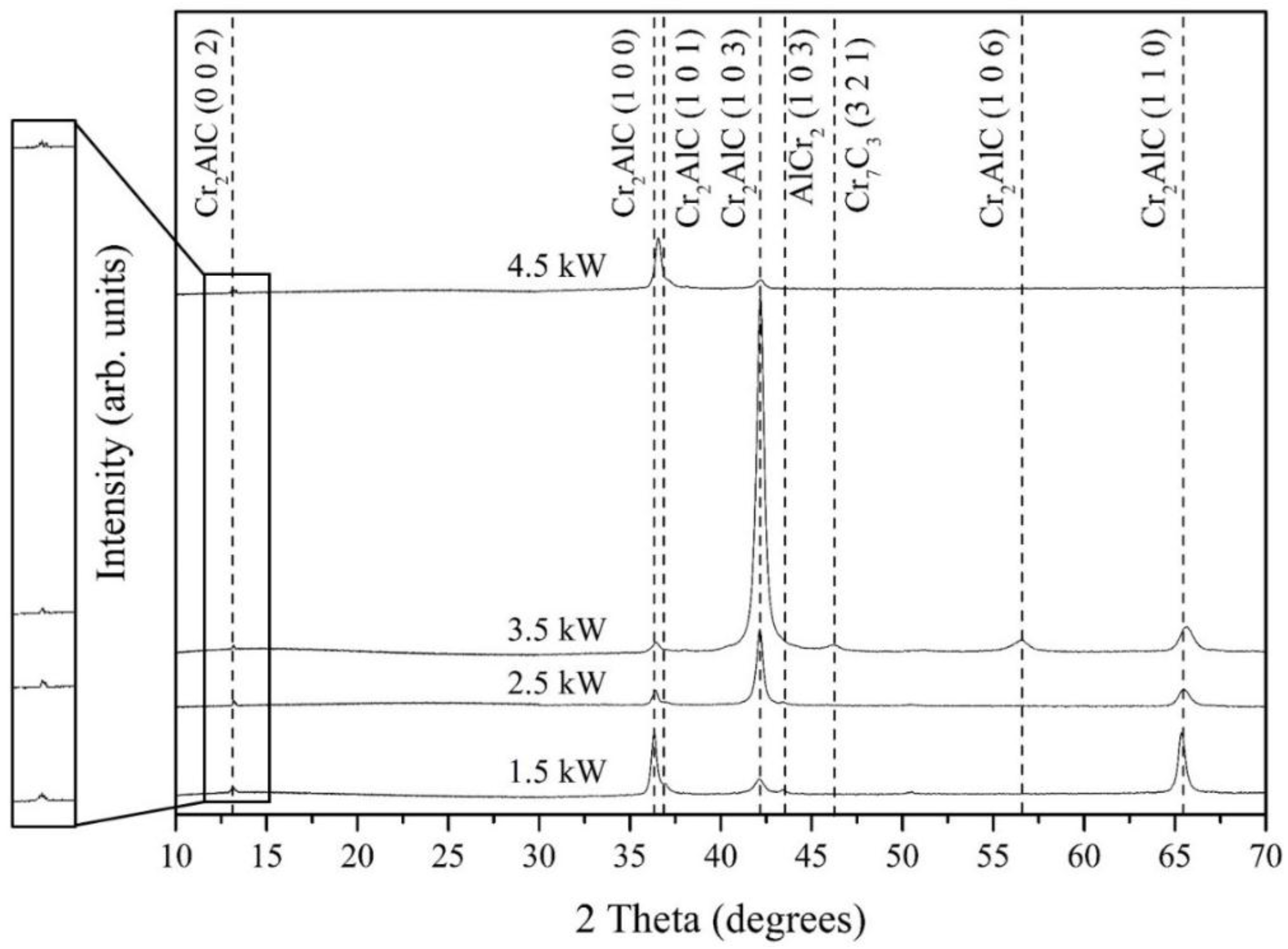
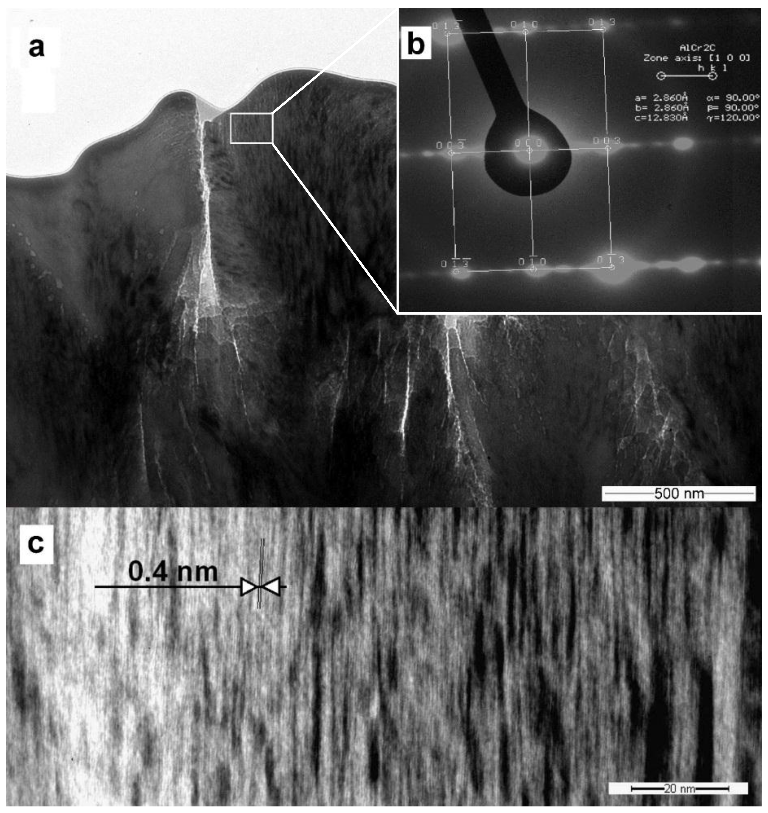
3.2. Phase Identification

To avoid reflections from the substrate material, low incident beam angle of 9° was chosen for the measurements. In the measured range (10°–70°) there are two super lattice reflections: (002) and (101), which correspond to ordered Cr2AlC MAX phase [32,41]. At approximately 13.3°, (002) weak reflection for all coatings was observed, identifying the presence of the MAX phase within the coating [32]. The (101) reflection cannot be clearly recognized, probably due to the coincidence with the (100) reflection [41]. XRD pattern of the film deposited with a cathode power of 1.5 kW reveals the presence of (100/101) and (110) planes (Figure 2), whereas coatings deposited at 2.5 kW and 3.5 kW show (103) preferred orientation growth. At 4.5 kW (100/101) planes preferential growth can be seen again with the disappearance of this (110) peak. A relatively high (110) plane intensity was observed at 1.5 kW compared with 2.5 kW. Further increase of the cathode power to 4.5 kW leads to a complete disappearance of this peak. This variation of preferred orientation with the sputtering power can be correlated with the accumulation of surface and strain energy during the coating process [42].
According to Chawla et al. [42], the surface and interface energies are responsible for controlling the coating preferred orientation. As the thickness of the coatings increases, higher strains appear within the coating, leading to coating growth control through strain energy [43]. A similar theory has been presented by Quaeyhaegegens et al. [44], who reported a change in preferential plane growth of TiN coatings with increased thickness. As reported in the previous section, higher coating thickness has been observed for 4.5 kW compared with 3.5 kW sputtering power for the same deposition time. Therefore, it can be assumed that a critical thickness of the coating was achieved at a sputtering power of 3.5 kW, which supports the coating growth in the (103) direction. After this thickness, the adatoms orient themselves in another preferential orientation due to strain energy, showing (100/101) dominant diffraction peaks at 4.5 kW. Moreover, the presence of intermetallic AlCr2 phase was identified for 1.5 kW and 2.5 kW, whereas Cr7C3 phase peak was found only at 3.5 kW. Comparison of all coatings shows that preferential (103) planes grew during the deposition process instead of (110) or (100/101). A dominant (103) diffraction peak has been reported by Zamulaeva et al. [45,46] for the Cr2AlC coatings deposited on Ti substrates, as well as by Field [47]. In contrast, Li et al. [48] discussed preferential coating growth at (110) planes taking place during deposition on the M38G super alloy. Hence, variations of the substrate, process kinetics, substrate surface energy, etc., can be regarded as influencing parameters affecting the coating growth.

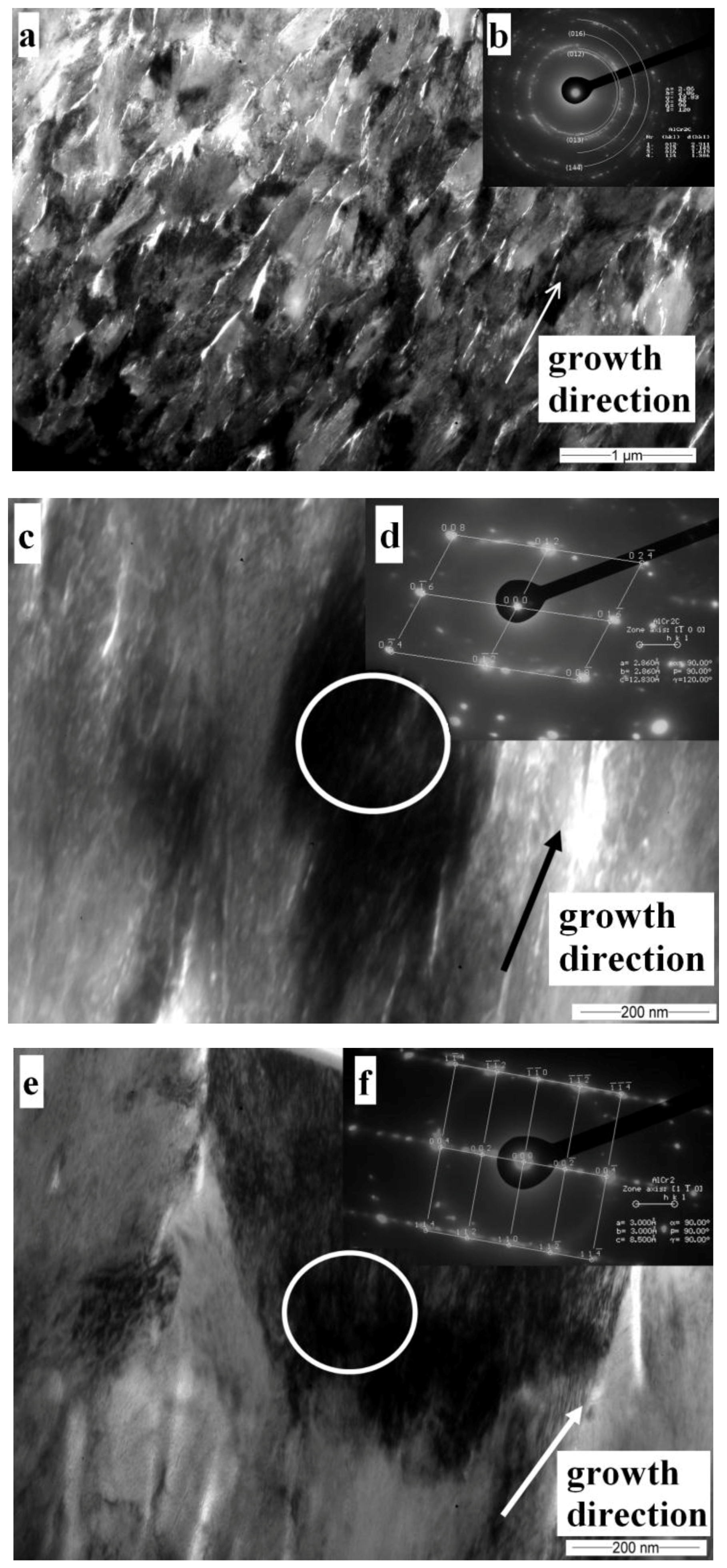
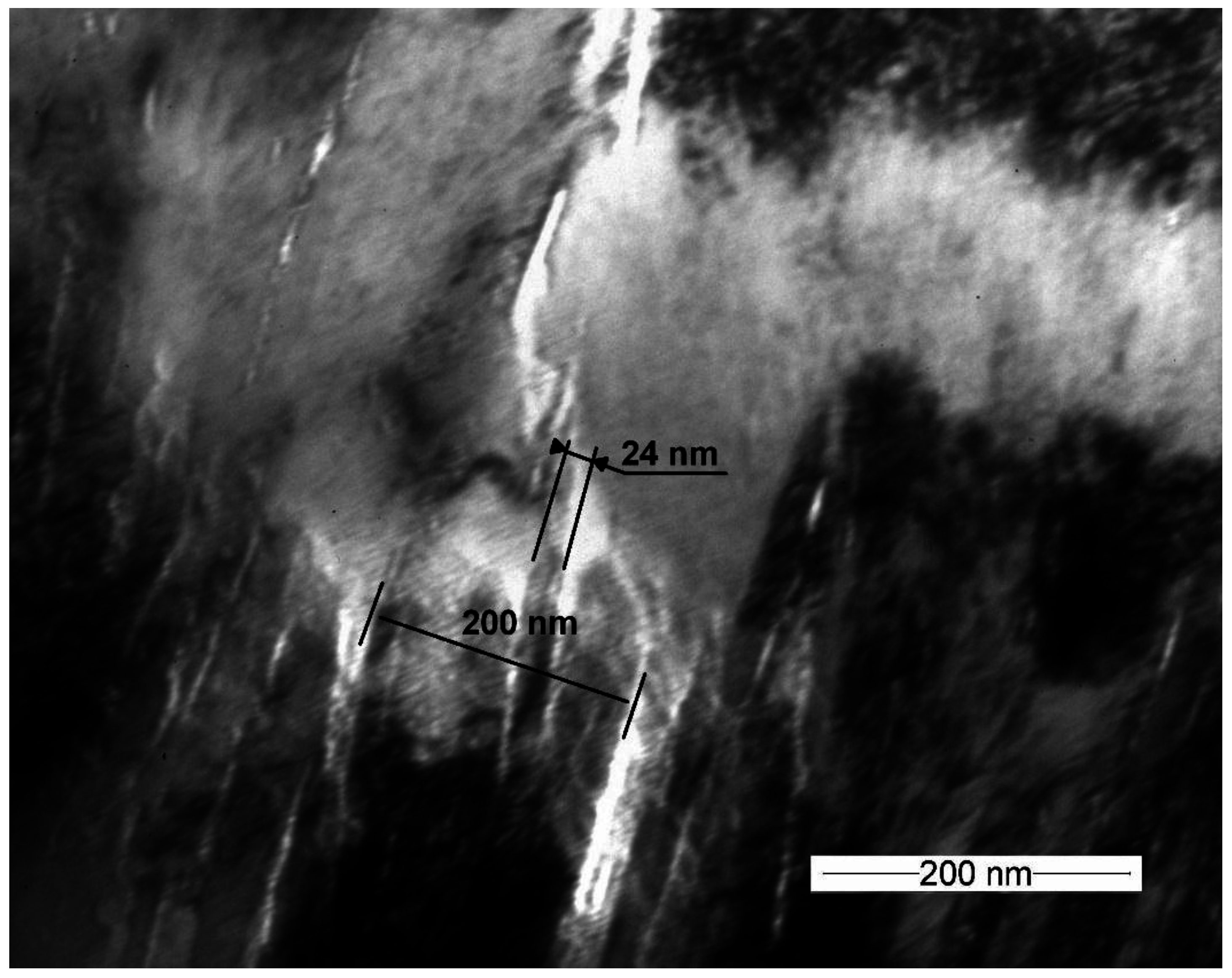
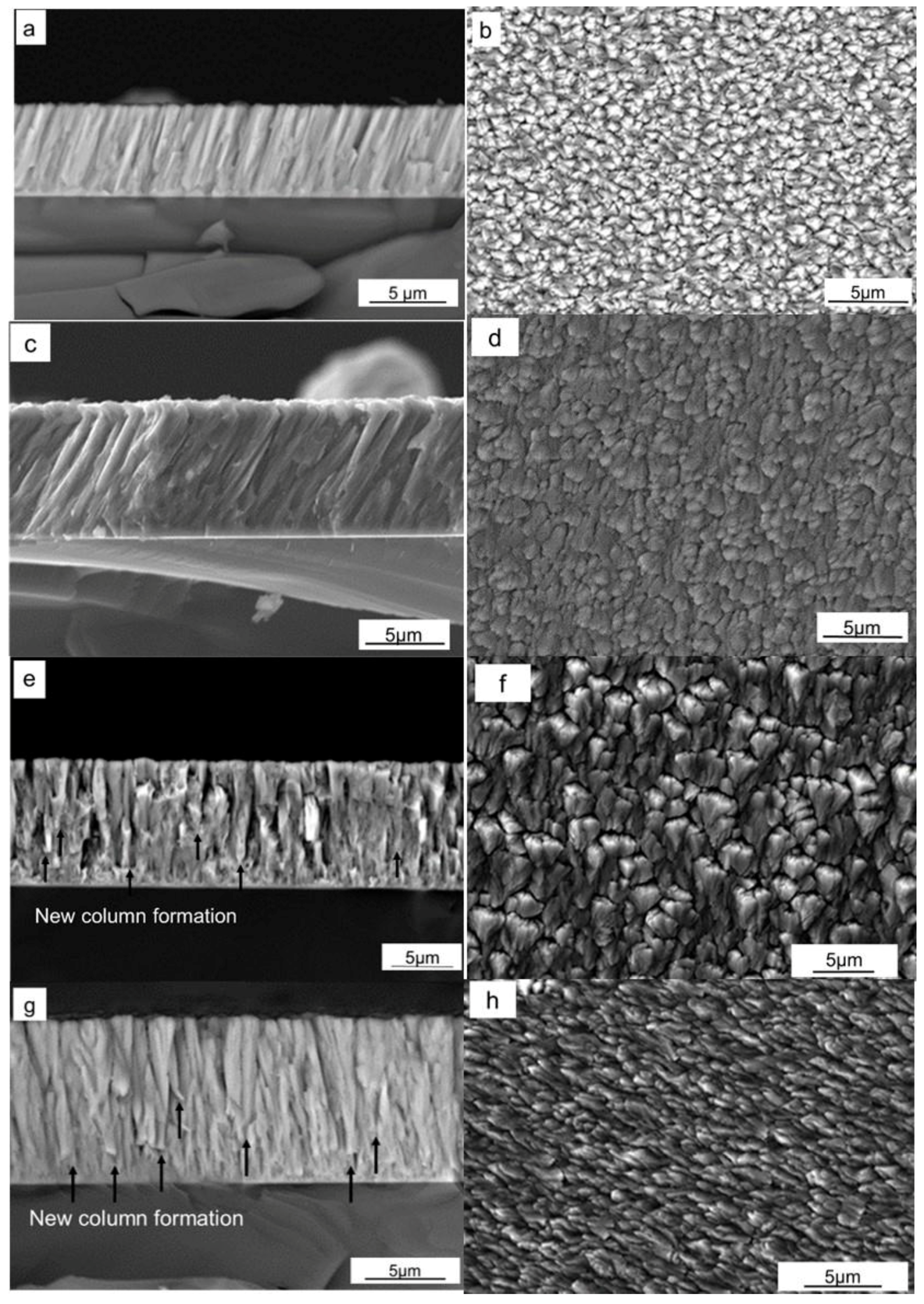
3.3. Coating Microstructure

A columnar structure of the deposited coatings can be seen in Figure 3. The coating deposited at 1.5 kW demonstrates column thickness in the 200–500 nm range in Figure 3a, whereas a corresponding surface morphology can be seen in Figure 3b. The column diameter increases during the deposition at 2.5 kW and the column size can be estimated above 500 nm (Figure 3c). At this sputtering power, a feathery flower-like structure appears on the surface of the coatings in Figure 3d. Up to 2.5 kW sputtering power, the coating columns grew with a certain orientation from the specimen normal with a dense structure. As the sputtering power was increased to 3.5 kW, the density of this flower structure increased on the surface of the coating, but a feathery appearance can still be seen in Figure 3f. Comparatively, porous structure is observed at lower sputtering power in Figure 3e. Strong renucleation of columns could be noticed during deposition at 4.5 kW (Figure 3e,f). This renucleation of columns can be regarded as density defect, which interrupts local epitaxy of the individual columns and takes place when the ion energy becomes large enough to support continuous coating growth [49]. A shark skin structure can be seen for the coating deposited at 4.5 kW in Figure 3h.
Cross-sectional TEM images of the Cr2AlC deposited at 2.5 kW were analyzed to evaluate the coating growth. The coating layer exhibits low porosity columnar structure in Figure 4a with 100–300 nm width range, oriented at ±15° angle with respect to the substrate normal. Selected area electron diffraction (SAED) images taken from an area near the substrate show the Cr2AlC phase presence. Discontinuous diffraction rings confirm polycrystalline structure of the coating and presence of a significant texture (Figure 4b). Columns of the Cr2AlC crystals present the local nanocrystalline structure and show [012] growth direction in Figure 4c,d. Presence of an intermetallic AlCr2 phase can be observed in the top layer of the coating too (Figure 4e). The grains show [112] orientation, which is nearly parallel to the main growth axis of the coating, while the [ 1 1 ¯ 0 ] direction is parallel to the incident electron beam. SAED reveals fuzzy streaks and extra diffraction spots along the [002] direction in Figure 4f. The reason of these supplementary diffraction spots could be the presence of a super lattice formed in the [002] direction, ordered stacking faults [50] or another long-range atomic plane arrangements. Low intermetallic phase presence is observed only for the coatings deposited at 1.5 and 2.5 kW, showing weak (103) reflections identified by the XRD measurements.
A bright field TEM image of the coating surface can be seen in Figure 5, showing 200 nm wide columns including a 24 nm sub-grain size. Moreover, these columns seem to be densely packed with low porosity. These results are in agreement with the SEM images as shown in Figure 4c,d.
Presence of the superlattice structure has also been found for some of the Cr2AlC crystals by TEM analysis in Figure 6a. SAED pattern obtained with an electron beam parallel to the [100] direction, reveals fuzzy streaks and extra diffraction spots along the [003] direction in Figure 6b. Estimation of the lattice parameters of this Cr2AlC hexagonal phase shows an interplanar distance of approximately 0.427 nm (Figure 6c). This is contrary to literature, as an interplaner distance of 1.2 nm was investigated for Cr2AlC lattice structure [22] which cannot be observed in our measurements due to the twinning effect [22].

3.4. Mechanical Properties

Hardness (H) and elastic modulus (E) of the Cr2AlC coatings are listed in Table 2. These two properties are selected for the present study as they describe the behavior of wear resisting materials. High hardness represents resistance against indenter penetration during plastic deformation whereas high E-Modulus leads to distribution of load on a large area [51]. In the current study, high hardness values of the deposited Cr2AlC coatings are measured as compared to literature [52,53]. Hardness and elastic modulus values of the deposited Cr2AlC coatings could be interpreted in terms of the sputtering power change. Elastic strain to failure (H/E), defined as significant factor in wear control [54], was calculated as an average value of 0.04 for the coatings. Plastic strain to failure (H3/E2) ratio, which defines the resistance of the material against plastic deformation [55], does not show large variations. In comparison, high plastic strain to plastic deformation of DLC [56] and TiAlN coatings [57] makes Cr2AlC inappropriate for wear applications.
A slight increase of hardness was observed with increasing sputtering power together with a constant elastic modulus. Thus, an increase in H/E and H3/E2 was calculated. At the sputtering power of 4.5 kW, a slight decrease in hardness was noticed, which could be related to the carbide formation within the coating. Ying et al. [52] found that different carbide phases and the amount of a particular carbide phase influence the mechanical properties (hardness and elastic modulus) of the coatings. They reported that a lower amount of the Cr7C3 phase (0%–14%) shows low hardness (4.7–5.5 GPa), whereas an increase above 17% resulted in values above 6 GPa. Similarly, hardness of the Cr3C2 carbide phase was reported between 15.1–18.9 GPa, which was correlated with the grain size of the corresponding phase [58]. Therefore, quantification of the phases through the Rietveld refinement would be a preferable method for correlating phases and mechanical properties. This approach will be discussed in further publications.

4. Conclusions

Columnar structure has been determined for all coatings with the presence of Cr2AlC MAX as the main phase along with traces of AlCr2 intermetallic as well as carbide phases. The Cr2AlC films observed by TEM showed nanocrystalline substructure with a column thickness in the 100–200 nm range along with high texture of the coatings. Moreover, an increase in coating growth occurred with the increase in sputtering power and a change in preferential coating growth orientation took place. Hardness and elastic modulus values indicate that these films cannot be introduced in aggressive wear applications due to low hardness. However, these coatings still have the capability to be used in high temperature and low friction applications due to their self-healing capabilities.

Acknowledgments

The authors are thankful to Florian Pyczak and Daniel Laipple (Helmholtz-Center Geesthacht, Germany) for the FIB specimen preparation. We are also thankful to Frank Holländer for his technical support during the research work.

Author Contributions

Muhammad Naveed carried out the deposition process, analyzed the results and prepared the manuscript. Aleksei Obrosov was responsible for carrying out detailed XRD and TEM analysis, was involved in manuscript writing along with the correction of the manuscript during the review phase. Andrzej Zak and Wlodzimierz Dudzinski provided the TEM observations and analyzed the SAED data. Alex A. Volinsky and Sabine Weiß did the revision and direction of the work.

Conflicts of Interest

The authors declare no conflict of interest.

References

  1. Barsoum, M.W. The MN + 1AXN phases: A new class of solids: Thermodynamically stable nanolaminates. Prog. Solid State Chem. 2000, 28, 201–281. [Google Scholar] [CrossRef]
  2. Schneider, J.M.; Sigumonrong, D.P.; Music, D.; Walter, C.; Emmerlich, J.; Iskandar, R.; Mayer, J. Elastic properties of Cr2AlC thin films probed by nanoindentation and ab initio molecular dynamics. Scr. Mater. 2007, 57, 1137–1140. [Google Scholar] [CrossRef]
  3. Hettinger, J.D.; Lofland, S.E.; Finkel, P.; Meehan, T.; Palma, J.; Harrell, K.; Gupta, S.; Ganguly, A.; El-Raghy, T.; Barsoum, M.W. Electrical transport, thermal transport, and elastic properties of M2AlC (M = Ti, Cr, Nb and V). Phys. Rev. B 2005, 72, 115120. [Google Scholar] [CrossRef]
  4. Barsoum, M.W.; El-Raghy, T. Synthesis and Characterization of a Remarkable Ceramic: Ti3SiC2. J. Am. Ceram. Soc. 1996, 79, 1953–1956. [Google Scholar] [CrossRef]
  5. Tzenov, N.V.; Barsoum, M.W. Synthesis and Characterization of Ti3AlC2. J. Am. Ceram. Soc. 2000, 83, 825–832. [Google Scholar] [CrossRef]
  6. Abdulkadhim, A.; Baben, M.; Takahashi, T.; Schnabel, V.; Hans, M.; Polzer, C.; Polcik, P.; Schneider, J.M. Crystallization kinetics of amorphous Cr2AlC thin films. Surf. Coat. Technol. 2011, 206, 599–603. [Google Scholar] [CrossRef]
  7. Song, G.M.; Pei, Y.T.; Sloof, W.G.; Li, S.B.; de Hosson, J.T.M.; van der Zwaag, S. Oxidation-induced crack healing in Ti3AlC2 ceramics. Scr. Mater. 2008, 58, 13–16. [Google Scholar] [CrossRef]
  8. Yang, H.J.; Pei, Y.T.; Rao, J.C.; de Hosson, J.T.M.; Li, S.B.; Song, G.M. High temperature healing of Ti2AlC: On the origin of inhomogeneous oxide scale. Scr. Mater. 2011, 65, 135–138. [Google Scholar] [CrossRef]
  9. Wang, P.; Mei, B.; Hong, X.; Zhou, W. Synthesis of Ti2AlC by hot pressing and its mechanical and electrical properties. Trans. Nonferr. Met. Soc. China 2007, 17, 1001–1004. [Google Scholar] [CrossRef]
  10. Naveed, M.; Renteria, A.F.; Nebel, D.; Weiß, S. Study of high velocity solid particle erosion behaviour of Ti2AlC MAX phase coatings. Wear 2015, 342–343, 391–397. [Google Scholar] [CrossRef]
  11. Hajas, D.E.; Baben, M.; Hallstedt, B.; Iskandar, R.; Mayer, J.; Schneider, J.M. Oxidation of Cr2AlC coatings in the temperature range of 1230 to 1410 °C. Surf. Coat. Technol. 2011, 206, 591–598. [Google Scholar] [CrossRef]
  12. Wang, X.H.; Zhou, Y.C. Intermediate-temperature oxidation behavior of Ti2AlC in air. J. Mater. Res. 2002, 17, 2974–2981. [Google Scholar] [CrossRef]
  13. Wang, X.H.; Zhou, Y.C. Oxidation behavior of Ti3AlC2 at 1000–1400 °C in air. Corros. Sci. 2003, 45, 891–907. [Google Scholar] [CrossRef]
  14. Tian, W.; Wang, P.; Kan, Y.; Zhang, G. Oxidation behavior of Cr2AlC ceramics at 1100 and 1250 °C. J. Mater. Sci. 2008, 43, 2785–2791. [Google Scholar] [CrossRef]
  15. Baben, M.; Shang, L.; Emmerlich, J.; Schneider, J.M. Oxygen incorporation in M2AlC (M = Ti, V, Cr). Acta Mater. 2012, 60, 4810–4818. [Google Scholar] [CrossRef]
  16. Li, J.J.; Qian, Y.H.; Niu, D.; Zhang, M.M.; Liu, Z.M.; Li, M.S. Phase formation and microstructure evolution of arc ion deposited Cr2AlC coating after heat treatment. Appl. Surf. Sci. 2012, 263, 457–464. [Google Scholar] [CrossRef]
  17. Lin, Z.J.; Li, M.S.; Wang, J.Y.; Zhou, Y.C. High-temperature oxidation and hot corrosion of Cr2AlC. Acta Mater. 2007, 55, 6182–6191. [Google Scholar] [CrossRef]
  18. Ding, H.; Glandut, N.; Fan, X.; Liu, Q.; Shi, Y.; Jie, J. First-principles study of hydrogen incorporation into the MAX phase Ti3AlC2. Int. J. Hydrog. Energy 2016, 41, 6387–6393. [Google Scholar] [CrossRef]
  19. Kashkarov, E.B.; Nikitenkov, N.N.; Sutygina, A.N.; Syrtanov, M.S.; Vilkhivskaya, O.V.; Pryamushko, T.S.; Kudiiarov, V.N.; Volesky, L. Effect of titanium ion implantation and deposition on hydrogenation behavior of Zr-1Nb alloy. Surf. Coat. Technol. 2016. [Google Scholar] [CrossRef]
  20. Kashkarov, E.B.; Nikitenkov, N.N.; Syrtanov, M.S.; Sutygina, A.N.; Shulepov, I.A.; Lider, A.M. Influence of plasma immersion titanium implantation on hydrogenation and mechanical properties of Zr-2.5Nb. Appl. Surf. Sci. 2016, 370, 142–148. [Google Scholar] [CrossRef]
  21. Fakih, H.; Jacques, S.; Berthet, M.P.; Bosselet, F.; Dezellus, O.; Viala, J.C. The growth of Ti3SiC2 coatings onto SiC by reactive chemical vapor deposition using H2 and TiCl4. Surf. Coat. Technol. 2006, 201, 3748–3755. [Google Scholar] [CrossRef]
  22. Eklund, P.; Beckers, M.; Jansson, U.; Högberg, H.; Hultman, L. The Mn + 1AXn phases: Materials science and thin-film processing. Thin Solid Films 2010, 518, 1851–1878. [Google Scholar] [CrossRef]
  23. Palmquist, J.-P.; Jansson, U.; Seppänen, T.; Persson, P.O.A.; Birch, J.; Hultman, L.; Isberg, P. Magnetron sputtered epitaxial single-phase Ti3SiC2 thin films. Appl. Phys. Lett. 2002, 81, 835–837. [Google Scholar] [CrossRef]
  24. Barsoum, M.W.; Radovic, M. Elastic and Mechanical Properties of the MAX Phases. Annu. Rev. Mater. Res. 2011, 41, 195–227. [Google Scholar] [CrossRef]
  25. Lee, D.B.; Nguyen, T.D. Cyclic oxidation of Cr2AlC between 1000 and 1300 °C in air. J. Alloy. Compd. 2008, 464, 434–439. [Google Scholar] [CrossRef]
  26. Wang, Q.M.; Renteria, A.F.; Schroeter, O.; Mykhaylonka, R.; Leyens, C.; Garkas, W.; Baben, M. Fabrication and oxidation behavior of Cr2AlC coating on Ti6242 alloy. Surf. Coat. Technol. 2010, 204, 2343–2352. [Google Scholar] [CrossRef]
  27. Smialek, J.L.; Garg, A. Interfacial reactions of a MAX phase/superalloy hybrid. Surf. Interface Anal. 2015, 47, 844–853. [Google Scholar] [CrossRef]
  28. Li, J.J.; Li, M.S.; Xiang, H.M.; Lu, X.P.; Zhou, Y.C. Short-term oxidation resistance and degradation of Cr2AlC coating on M38G superalloy at 900–1100 °C. Corros. Sci. 2011, 53, 3813–3820. [Google Scholar] [CrossRef]
  29. Cabioch, T.; Eklund, P.; Mauchamp, V.; Jaouen, M.; Barsoum, M.W. Tailoring of the thermal expansion of Cr2(Alx,Ge1−x)C phases. J. Eur. Ceram. Soc. 2013, 33, 897–904. [Google Scholar] [CrossRef]
  30. Mertens, R.; Sun, Z.; Music, D.; Schneider, J.M. Effect of the Composition on the Structure of Cr-Al-C Investigated by Combinatorial Thin Film Synthesis and ab Initio Calculations. Adv. Eng. Mater. 2004, 6, 903–907. [Google Scholar] [CrossRef]
  31. Schneider, J.M.; Sun, Z.; Mertens, R.; Uestel, F.; Ahuja, R. Ab initio calculations and experimental determination of the structure of Cr2AlC. Solid State Commun. 2004, 130, 445–449. [Google Scholar] [CrossRef]
  32. Grieseler, R.; Hähnlein, B.; Stubenrauch, M.; Kups, T.; Wilke, M.; Hopfeld, M.; Pezoldt, J.; Schaaf, P. Nanostructured plasma etched, magnetron sputtered nanolaminar Cr2AlC MAX phase thin films. Appl. Surf. Sci. 2014, 292, 997–1001. [Google Scholar] [CrossRef]
  33. Walter, C.; Sigumonrong, D.P.; El-Raghy, T.; Schneider, J.M. Towards large area deposition of Cr2AlC on steel. Thin Solid Films 2006, 515, 389–393. [Google Scholar] [CrossRef]
  34. Wilhelmsson, O.; Palmquist, J.-P.; Nyberg, T.; Jansson, U. Deposition of Ti2AlC and Ti3AlC2 epitaxial films by magnetron sputtering. Appl. Phys. Lett. 2004, 85, 1066–1068. [Google Scholar] [CrossRef]
  35. Le, M.-T.; Sohn, Y.-U.; Lim, J.-S.; Choi, G.-S. Effect of Sputtering Power on the Nucleation and Growth of Cu Films Deposited by Magnetron Sputtering. Mater. Trans. 2010, 51, 116–120. [Google Scholar] [CrossRef]
  36. Wang, P.; Takeno, T.; Fontaine, J.; Aono, M.; Adachi, K.; Miki, H.; Takagi, T. Effects of substrate bias voltage and target sputtering power on the structural and tribological properties of carbon nitride coatings. Mater. Chem. Phys. 2014, 145, 434–440. [Google Scholar] [CrossRef]
  37. Rossnagel, S.M.; Hopwood, J. Magnetron sputter deposition with high levels of metal ionization. Appl. Phys. Lett. 1993, 63, 3285–3287. [Google Scholar] [CrossRef]
  38. Naveed, M.; Obrosov, A.; Weiß, S. Investigation of the Wear Resistance Properties of Cr/CrN Multilayer Coatings against Sand Erosion. Conf. Pap. Sci. 2015, 2015, 9. [Google Scholar] [CrossRef]
  39. Oliver, W.C.; Pharr, G.M. An improved technique for determining hardness and elastic modulus using load and displacement sensing indentation experiments. J. Mater. Res. 1992, 7, 1564–1583. [Google Scholar] [CrossRef]
  40. Farooq, M.; Lee, Z.H. Optimization of the sputtering process for depositing composite thin films. J. Korean Phys. Soc. 2002, 40, 511–515. [Google Scholar]
  41. Berger, O.; Leyens, C.; Heinze, S.; Boucher, R.; Ruhnow, M. Characterization of Cr–Al–C and Cr–Al–C–Y films synthesized by High Power Impulse Magnetron Sputtering at a low deposition temperature. Thin Solid Films 2015, 580, 6–11. [Google Scholar] [CrossRef]
  42. Chawla, V.; Jayaganthan, R.; Chawla, A.K.; Chandra, R. Microstructural characterizations of magnetron sputtered Ti films on glass substrate. J. Mater. Process. Technol. 2009, 209, 3444–3451. [Google Scholar] [CrossRef]
  43. Thompson, C.V. Structure evolution during processing of polycrystalline films. Annu. Rev. Mater. Sci. 2000, 30, 159–190. [Google Scholar] [CrossRef]
  44. Quaeyhaegens, C.; Knuyt, G.; D′Haen, J.; Stals, L.S. Experimental study of the growth evolution from random towards a (111) preferential orientation of PVD TiN coatings. Thin Solid Films 1995, 258, 170–173. [Google Scholar] [CrossRef]
  45. Zamulaeva, E.I.; Levashov, E.A.; Sviridova, T.A.; Shvyndina, N.V.; Petrzhik, M.I. Pulsed electrospark deposition of MAX phase Cr2AlC based coatings on titanium alloy. Surf. Coat. Technol. 2013, 235, 454–460. [Google Scholar] [CrossRef]
  46. Zamulaeva, E.I.; Levashov, E.A.; Skryleva, E.A.; Sviridova, T.A.; Kiryukhantsev-Korneev, P.V. Conditions for formation of MAX phase Cr2AlC in electrospark coatings deposited onto titanium alloy. Surf. Coat. Technol. 2016, 298, 15–23. [Google Scholar] [CrossRef]
  47. Field, M.R.; Carlsson, P.; Eklund, P.; Partridge, J.G.; McCulloch, D.G.; McKenzie, D.R.; Bilek, M.M.M. A combinatorial comparison of DC and high power impulse magnetron sputtered Cr2AlC. Surf. Coat. Technol. 2014, 259, 746–750. [Google Scholar] [CrossRef]
  48. Li, J.J.; Hu, L.F.; Li, F.Z.; Li, M.S.; Zhou, Y.C. Variation of microstructure and composition of the Cr2AlC coating prepared by sputtering at 370 and 500 °C. Surf. Coat. Technol. 2010, 204, 3838–3845. [Google Scholar] [CrossRef]
  49. Petrov, I.; Barna, P.B.; Hultman, L.; Greene, J.E. Microstructural evolution during film growth. J. Vac. Sci. Technol. A 2003, 21, S117–S128. [Google Scholar] [CrossRef]
  50. Dudzinski, W.; Morniroli, J.P.; Gantois, M. Stacking faults in chromium, iron and vanadium mixed carbides of the type M7C3. J. Mater. Sci. 1980, 15, 1387–1401. [Google Scholar] [CrossRef]
  51. Kim, G.S.; Lee, S.Y.; Hahn, J.H.; Lee, S.Y. Synthesis of CrN/AlN superlattice coatings using closed-field unbalanced magnetron sputtering process. Surf. Coat. Technol. 2003, 171, 91–95. [Google Scholar] [CrossRef]
  52. Ying, G.; He, X.; Li, M.; Du, S.; Han, W.; He, F. Effect of Cr7C3 on the mechanical, thermal, and electrical properties of Cr2AlC. J. Alloy. Compd. 2011, 509, 8022–8027. [Google Scholar] [CrossRef]
  53. Hopfeld, M.; Grieseler, M.; Vogel, A.; Romanus, H.; Schaaf, P. Tribological behavior of selected Mn + 1AXn phase thin films on silicon substrates. Surf. Coat. Technol. 2014, 257, 286–294. [Google Scholar] [CrossRef]
  54. Leyland, A.; Matthews, A. On the significance of the H/E ratio in wear control: A nanocomposite coating approach to optimised tribological behaviour. Wear 2000, 246, 1–11. [Google Scholar] [CrossRef]
  55. Musil, J. Hard and superhard nanocomposite coatings. Surf. Coat. Technol. 2000, 125, 322–330. [Google Scholar] [CrossRef]
  56. Voevodin, A.A.; Zabinski, J.S. Superhard, functionally gradient, nanolayered and nanocomposite diamond-like carbon coatings for wear protection. Diam. Relat. Mater. 1998, 7, 463–467. [Google Scholar] [CrossRef]
  57. Musil, J.; Hrubý, H. Superhard nanocomposite Ti1−xAlxN films prepared by magnetron sputtering. Thin Solid Films 2000, 365, 104–109. [Google Scholar] [CrossRef]
  58. Hirota, K.; Mitani, K.; Yoshinaka, M.; Yamaguchi, O. Simultaneous synthesis and consolidation of chromium carbides (Cr3C2, Cr7C3 and Cr23C6) by pulsed electric-current pressure sintering. Mater. Sci. Eng. A 2005, 399, 154–160. [Google Scholar] [CrossRef]
Figure 1. Relationship between the sputtering power and deposition rate of the Cr2AlC coatings.
Metals 06 00265 g001
Figure 2. X-ray diffraction (XRD) spectra of Cr2AlC coatings deposited at various sputtering power.
Metals 06 00265 g002
Figure 3. (a,c,e,g) Cross-sectional; and (b,d,f,h) surface morphology of Cr2AlC coatings deposited at: (a,b) 1.5 kW; (c,d) 2.5 kW; (e,f) 3.5 kW; and (g,h) 4.5 kW, respectively.
Metals 06 00265 g003
Figure 4. (a,c,e) Bright-field images; and (b,d,f) calculated SAED patterns of Cr2AlC coating deposited at 2.5 kW sputtering power. SAED patterns were taken from the marked areas.
Metals 06 00265 g004
Figure 5. Bright-field image of the Cr2AlC coating deposited at 2.5 kW sputtering power, showing column width and nanoscale subgrains.
Metals 06 00265 g005
Figure 6. (a) Bright-field image and (b) the corresponding calculated SAED pattern and (c) magnification showing (003) lattice image of the Cr2AlC coating deposited at 2.5 kW sputtering power.
Metals 06 00265 g006
Table 1. Deposition parameters of the Cr2AlC coatings.
ProcessParameterValue
HeatingTemperature, T550 °C
Time, t1.5 h
Argon EtchingTemperature, T550 °C
Bias Voltage, V−650 V
Argon Pressure, PAr350 mPa
Time, t0.5 h
DepositionTemperature, T550 °C
Cathode Power, P1.5 kW/2.5 kW/3.5 kW/4.5 kW
Bias Voltage, V−60 V
Argon Pressure, PAr600 mPa
Time, t0.5 h
Table 2. Influence of the sputtering power on mechanical properties of the Cr2AlC coatings.
Cathode Power, kWHardness, GPaElastic modulus, GPaH/EH3/E2, GPa
1.511.5 ± 2.8288.6 ± 84.70.03 ± 0.020.018 ± 0.02
2.512.1 ± 4.7287.2 ± 88.80.04 ± 0.020.021± 0.03
3.513.9 ± 4.6289.2 ± 1110.04 ± 0.030.032 ± 0.05
4.512.3 ± 2.0281.1 ± 54.50.04 ± 0.010.023 ± 0.02

