Review

Ductility of Nanostructured Bainite

by
Lucia Morales-Rivas
1,2,
Carlos Garcia-Mateo
2,*,
Thomas Sourmail
3,
Matthias Kuntz
4,
Rosalia Rementeria
2 and
Francisca G. Caballero
2
1
University of Kaiserslautern, Materials Testing, Gottlieb-Daimler-Str., Kaiserslautern 67663, Germany
2
Department of Physical Metallurgy, National Center for Metallurgical Research (CENIM-CSIC), Avenida Gregorio del Amo, 8, Madrid 28040, Spain
3
Asco Industries CREAS (Research Centre) Metallurgy, BP 70045, Hagondange Cedex 57301, France
4
Robert Bosch GmbH, Materials- and Process Engineering Metals, Renningen, Stuttgart 70465, Germany
*
Author to whom correspondence should be addressed.
Metals 2016, 6(12), 302; https://doi.org/10.3390/met6120302
Submission received: 25 October 2016 / Revised: 21 November 2016 / Accepted: 25 November 2016 / Published: 2 December 2016

Abstract

:
Nanostructured bainite is a novel ultra-high-strength steel-concept under intensive current research, in which the optimization of its mechanical properties can only come from a clear understanding of the parameters that control its ductility. This work reviews first the nature of this composite-like material as a product of heat treatment conditions. Subsequently, the premises of ductility behavior are presented, taking as a reference related microstructures: conventional bainitic steels, and TRIP-aided steels. The ductility of nanostructured bainite is then discussed in terms of work-hardening and fracture mechanisms, leading to an analysis of the three-fold correlation between ductility, mechanically-induced martensitic transformation, and mechanical partitioning between the phases. Results suggest that a highly stable/hard retained austenite, with mechanical properties close to the matrix of bainitic ferrite, is advantageous in order to enhance ductility.

1. Nanostructured Bainite: Heat-Treatments and Microstructure

There is an increasing interest in nanocrystalline steels because of their unique mechanical properties, achieving ultra-high strength while maintaining good values of ductility [1,2]. However, the manufacture of nanocrystalline steels is frequently very cost-consuming, involving the addition of expensive alloying elements, severe plastic deformation or complex thermomechanical routes in order to obtain the desired refinement of the microstructure during the material processing. A new generation of steels, nanostructured bainitic steels, is one promising solution because of the simplicity in terms of alloy design and processing. On the one hand, they are low-alloyed steels, with a typical chemical composition range being: (0.6–1)C-(≥1.5)Si-(0.7–2)Mn-(0.4–1.7)Cr-(0–0.2)Mo wt % [3]. On the other hand, the heat treatment consists of complete austenitization followed by isothermal holding at temperature T as low as T/Tm < 0.25, where Tm is the absolute melting temperature. The transformation itself leads to the nanocrystalline structure without further technological efforts, and has received much attention in recent years [4,5,6,7]. These novel microstructures have achieved the highest strength-toughness combinations ever recorded in bainitic steels (2.2 GPa–30 MPa·m1/2) [8,9,10,11].
The microstructure of nanostructured bainite consists basically of two phases: a hard matrix of bainitic ferrite and a carbon-enriched retained austenite, the second dispersed phase. It is characterized by the lack of coarse precipitates of cementite, due to the addition of Si with resulting content of near 1.5 wt %, and by the absence of martensitic islands in the initial microstructure, both detrimental to the mechanical properties. The typically high C bulk content in nanostructured bainitic steels, resulting in a decrease of the bainitic transformation temperature down to 200–300 °C, is the main reason for the formation of plates of bainitic ferrite with a thickness of some tens of nanometers. Even though the growth of bainitic ferrite is not controlled by any diffusive process, temperatures at which the bainitic transformation typically takes place are high enough to allow C atoms to diffuse. Therefore, soon after the diffusionless growth of a bainitic ferrite plate is completed, C, which is in excess in solid solution, is expelled into the retained austenite [3,12]. This enrichment of austenite in C in solid solution after the bainitic transformation, ranging from 0.5–1.5 wt %, is responsible for the reduction of the martensitic start temperature, Ms, below room temperature. Thus, austenite remains untransformed, having two very distinguishable morphologies: thin films trapped between the plates of bainitic ferrite and coarser blocks [13,14,15], Figure 1a,b.
The heat treatment settings have a great influence on the scale and the nature of the initial microstructure. The increase of the bainitic formation temperature leads to a coarser microstructure, as can be seen by comparing the microstructures in Figure 1 (the same steel treated at two different temperatures, 250 °C and 350 °C) [15], which can be characterized by morphological parameters such as the bainitic ferrite plate thickness and the austenite block/film size. In addition, due to the transformation mechanisms, higher transformation temperatures result in higher retained austenite contents.
A combined study using three different techniques, atom probe tomography (APT), X ray diffraction (XRD) and high-resolution transmission electron microscopy (HR-TEM) was performed in order to get a new insight into the placement of C in nanostructured bainite, and its correlation with the bainitic ferrite crystal structure [16]. Different alloys were studied, after treatments at different temperatures or with holding times equal and longer than strictly necessary for the bainitic transformation; and also adding in some cases a subsequent tempering stage. This work indicated that as the bainitic transformation temperature increases there is a significant reduction of the C content in the defect-free solid solution of the bainitic ferrite. The calculated C concentration of bainitic ferrite in samples from different alloys treated between 220 °C and 300 °C were reported to range between 0.19 wt % (0.88 at %) and 0.16 wt % (0.71 at %), according to XRD. It showed an excellent level of agreement when compared with those measured by APT. In the latter work, it was suggested from XRD results that a tetragonal bainitic ferrite structure, also observed by HR-TEM, allows these amounts of C to be accommodated, in the same way as in martensite [17,18]. The tetragonality seems to be stronger as the bainitic transformation temperature decreases, and there is a big reluctance of C to partition from defect-free solid solution in bainitic ferrite into the adjacent austenite during extended treatments or tempering [19,20]. Besides this, there are important amounts of C deficit, undetectable to the XRD technique, which can be trapped at boundaries, at dislocations, or forming clusters, etc. Regarding the dislocations, the segregation of C at these defects within the ferrite phase, known as Cottrell atmospheres, can have a C concentration peak of 8 at %, and this C enriched region can extend ~7 nm from the dislocation core [21]. The C deficit tends to decrease as the transformation temperature increases; it has been reported that a reduction from 0.39 wt % (1.7 at %) to 0.08 wt % (0.4 at %) for a steel treated at 220 °C and 350 °C, respectively, which was in good agreement with APT results. This indicates a stronger preference of C for being held in austenite in solid solution in samples treated at higher temperatures. It can even counteract the fact that a higher austenite fraction is available, resulting in higher austenite C contents as the treatment temperature increases.
Other interesting information that can also be determined from XRD analyses, by the double-Voigt approach, are the microstrain (εmicro_α) and the crystallite size (CS) of bainitic ferrite. The CS is a measure of the smallest undistorted region (defect free) in a crystal, i.e., a coherently diffracting domain of bainitic ferrite. It is observed that the average volume-weighted crystallite size of the bainitic ferrite plates normally increases by several nanometers as the transformation temperature increases, while the measured microstrain decreases [16], a behavior which is consistent with the bainitic transformation itself, the microstructure becoming thinner and with a higher dislocation density when the transformation temperature is lowered [3,22]. The lower density of defects present in microstructures treated at higher temperatures, i.e., a more recovered bainitic ferrite, may be an indirect proof supporting the previous observations on C locations. In this sense, it seems that the amount of C deficit is higher in microstructures containing more C trapping sites, such as dislocations and other features.
It is important to highlight that although the initial nanobainitic structure is formed just by retained austenite and bainitic ferrite, the former phase can transform into martensite when mechanically loaded, therefore giving rise to an evolving complex microstructure. There is no agreement on whether this mechanically-induced transformation is stress- or strain-assisted for the case of nanostructured bainite. In the first situation, stress-assisted, martensitic nucleation would take place on the same heterogeneous sites responsible for the transformation on cooling. In the second situation, strain-assisted, martensitic transformation would take place thanks to the new nucleation sites being created; that is, prior plastic strain is necessary to trigger the martensitic transformation under this condition [23,24]. The mechanical stability of austenite depends on both intrinsic and extrinsic parameters [25]. Intrinsic parameters are the chemical composition and the size/shape of the features. In these bainitic structures, the only alloying element whose content differs from one austenite feature to another is the C. In this sense, nanofilms of austenite are more enriched in C than submicron blocks of austenite [20,26]. This fact, together with the size/shape heterogeneity, results in a distribution of the stability of austenite within one microstructure, the finest austenite features being the most stable [27,28,29,30,31,32]. In addition, external factors such as the strength of the surrounding bainitic ferrite as compared to the austenite, and the relative phase fraction, play an important role in the stability of the retained austenite as well [33,34,35,36].
All the involved deformation mechanisms, which depend on the specific characteristics of the different nanobainitic structures, are relevant to the plastic deformation capability of this material. Extensive research has been carried out to understand the mechanisms and microstructural parameters that control the strength of nanostructured bainite, however studies on the correlation between them and the elongation values are more recent. It is the objective of this work to review the factors that affect the mechanical properties, putting the focus on ductility.

2. Mechanical Properties of Nanostructured Bainite

Figure 2 shows the typical true strain-stress curves from tensile tests at room temperature, for two different nanobainitic structures [37].
The yield strength of ferrite alone, YSα, is function of several parameters, summarized in the following expression [3,38,39]:
Y S α = σ Fe + i σ ss i + σ c + 115 L α 1 + k p Ω 1 + 7.341 × 10 6 ρ d 0.5
where σFe is the strength of pure annealed Fe; σ ss i is the solid solution strengthening due to the alloying element i; σc is the solid solution strengthening due to the C; Lα [μm] is the mean intercept line of the ferrite plate measured in a direction normal to the plate length; kp is a constant; Ω the distance between a carbide particle and the nearest two or three neighbors; and ρd the dislocation density.
In the case of bainitic ferrite, the main parameter influencing its strength, directly and indirectly, is the C content. The direct effect is accounted for by the term σc in Equation (1), i.e., the strengthening of the phase by C in solid solution. The indirect effect is the refinement of the microstructure thanks to the decrease of treatment temperatures leading to nanostructured bainite. The low temperatures of bainitic transformation for nanostructured bainite are mainly a consequence of the high C contents of these steels. The term 115 L α 1 measures the strengthening due to this refinement of the bainitic ferrite plates. This is not the traditional Hall-Petch relation, but the Langford and Cohen one, due to the nanoscale of the bainitic plates. Another important strengthening parameter is the dislocation density.
On the other hand, the yield strength of austenite alone, YSγ, can be described as a function of the alloying content in solid solution and the temperature as [38,40,41]:
Y S γ = ( 1 0.26 × 10 2 ( T 248 ) + 0.47 × 10 5 ( T 248 ) 2 0.326 × 10 8 ( T 248 ) 3 ) × 15.4 ( 4.4 + 23 w C γ + 1.3 w Si γ + 0.24 w Cr γ + 0.9 w Mo γ + 32 w N γ )
where T (K) is the temperature and w i γ , the content in wt % of the element i in solid solution in austenite.
Considering the whole microstructure, the yield strength (YS) has been found to be mainly controlled by the amount and scale of the bainitic ferrite [10,42]. In this sense, the yield strength correlates well with the ratio Vα/tα see Figure 3) where Vα is the volume fraction of ferrite and tα the mean bainitic plate thickness (tα is Lα after stereological correction [43,44]). The higher the fraction of thinner bainitic ferrite plates, the higher the yield strength, which suggests that bainitic ferrite is the hardest phase, while the retained austenite is the softest one. Lan et al. [45] also showed by means of nano-indentation that the nanohardness of thin bainitic ferrite plates in the nanostructured steel exceeds that of the retained austenite.
The ultimate tensile strength (UTS) seems less sensitive to the same parameter, Vα/tα, than YS. According to Figure 3, low YS values allow the material to work-harden when plastically deformed, increasing the UTS/YS ratio.
As opposed to the yield strength, the mechanisms underlying the enhancement of ductility are far from being understood, and are addressed in the following sections.

3. General Considerations on Ductility

As a general rule, a high ductility can be achieved by both the work-hardening capability of the material and its damage resistance [46]. On one hand, the work-hardening is responsible of the delay of necking formation, which contributes to retard the plastic instability and thus, increase the uniform elongation (eu). On the other hand, the damage resistance, which depends on the fracture mode, is key in controlling the total elongation (et) of the material. Both issues are detailed below, where the behaviors of other microstructures with certain similarities to nanostructured bainite are reviewed.

3.1. General Considerations on Work-Hardening

As mentioned, strength and uniform elongation are rivaling properties, i.e., it is very difficult to increase the stress level that can be sustained by a material without reducing its resistance to the localization of deformation [47]. However, a high work-hardening rate, i.e., the increase of stress for an increase of strain, brings about high values of both UTS and eu, from moderate values of YS. It is well known that steels containing retained austenite can transform into martensite when mechanically loaded. The efficiency of the martensitic transformation as a deformation mechanism enhancing the work-hardening rate is expressed by the concept of transformation induced plasticity (TRIP) effect [47,48]. Conventional TRIP-aided steels take advantage of such mechanically induced transformation, skillfully combining several mechanisms of strengthening and softening. These microstructures consist of a soft matrix of polygonal ferrite and dispersed small martensite-austenite grains. In some cases, a dispersed microconstituent, e.g., bainite, consisting of bainitic ferrite plus retained austenite is also present. In conventional TRIP-aided steels, two work-hardening mechanisms can effectively be argued [49]: the TRIP effect and the composite-like nature of their microstructures.
The TRIP effect includes the shape and volume changes accompanying the transformation of austenite to martensite, which generate local plasticity in the surrounding ferrite grains [50]. However, the associated increase of the dislocation density cannot entirely explain the high work-hardening levels exhibited by the TRIP-aided steels. The composite nature of the microstructures cannot be neglected. The large variability of mechanical properties between the phases results in stress and strain partitioning during loading [33,34]. Hence, in conventional TRIP-aided steels, an important contribution to the strengthening comes from the fact that there is an evolving composite microstructure, in which a hard phase, martensite, is progressively added upon deformation. Since the proportions of austenite and martensite continuously change during straining, the mechanical partitioning between phases also becomes modified. The macroscopic stress-strain response is therefore a complex coupling of different phenomena taking place upon deformation.
As a result of these mechanisms, in conventional TRIP-steels, the best strength-ductility balance is known to occur when there is a progressive martensitic transformation during the deformation process. See in Figure 4 two examples of typical true stress-strain curves of TRIP aided-steels. The effective TRIP effect produces a long elongation, at which a high strength level is also achieved [47].
It is well known that in bainitic steels the retained austenite can transform into martensite (α′) when subjected to loading. However, as opposed to conventional TRIP steels, in bainitic steels the retained austenite is embedded in a matrix of hard bainitic ferrite, and thus the implications of the TRIP effect and the composite behavior diverge, as will be shown.

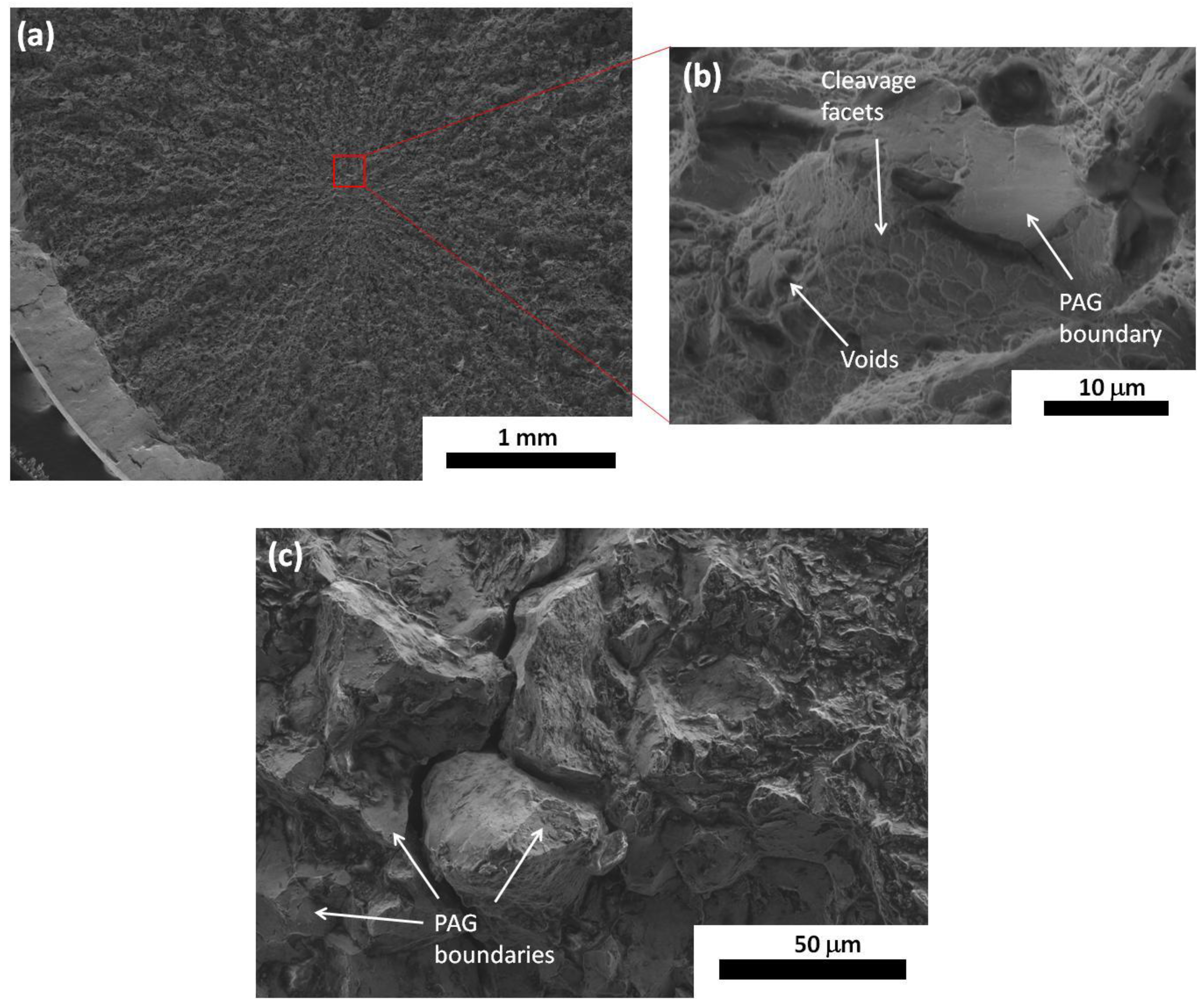
3.2. General Considerations on Fracture Mechanisms

Ductile fracture occurs normally in good quality steels (which do not contain many non-metallic inclusions) via nucleation growth and coalescence of voids. Macroscopic fracture takes place when the voids link on a large scale. If the number density of voids is large, then their mean separation is reduced and coalescence occurs rapidly, with little plastic deformation before fracture, i.e., a small overall ductility. In conventional bainitic steels, coarse cementite particles are responsible for void nucleation, following that the ductility must decrease with increasing carbide density. In bainitic steels which contain fresh (untempered) martensite, ductile void formation occurs at the hard martensite features, which undergo brittle failure allowing the voids to grow. In these cases of ductile void formation, a high work-hardening rate should result in an increase in uniform elongation (since necking instability depends on the rate of work-hardening) and thus of the ductility [3]. However, in some conventional bainitic steels it has been found that a high rate of work-hardening is not always beneficial in terms of ductility [51]. Therefore, the ductility of the material cannot be understood while only considering work-hardening.
In nanostructured bainite, as opposed to other bainitic steels, the microstructure contains retained austenite instead of coarse particles of cementite, and thus other fracture mechanisms must be involved. Even though fresh martensite is absent, the earlier mechanically-assisted martensitic transformation of austenite features might play a role. In TRIP-assisted steels, the crack development and the fracture mode are a consequence of the mechanical incompatibility between the phases and/or an ineffective TRIP contribution [46]. The distribution of austenite is relevant, since it is related to the micro-crack connection of the failed features [52].
Work-hardening and fracture analyses of nanostructured bainite are described in the next two sections. In the following, the threefold relationship between the retained austenite nature, the mechanical-partitioning between the phases, and the ductility in nanostructured bainite are addressed.

4. Ductility: Work-Hardening and Fracture Mechanisms in Nanostructured Bainite

When considering the plastic behavior of nanostructured bainite, the presence of mobile dislocations is in part responsible for the observed continuous yielding. The increase of work-hardening, calculated as the ratio between the measured UTS and the YS, does not result in the enhancement of the uniform elongation (eu), see Figure 5a, with data from reference [53]. This phenomenon in nanostructured bainite is opposed to the typical trend in other steels, as shown previously in Figure 4, where a lower YS allows the work-hardening (associated to the TRIP effect) to expand, retarding the moment (strain) at which maximum stress is reached. There is no correlation between the elongation and the strength of the material (yield strength and UTS, separately) either, as seen in Figure 5b,c, with data from reference [53]. On the other hand, it has been reported that the samples with a high ductility present a stronger damage resistance [54]. This can be evaluated with another parameter, UTS·et, , which is a measure of the toughness, as in Figure 5d, with data from reference [53], where the correlation is confirmed. The significant presence of film-like austenite features is thought to be in part responsible for that phenomenon [55,56]. It resembles the behavior of martensitic microstructures containing “reverted austenite” (newly formed austenite from martensite after annealing), where their nanolaminate morphology has been reported to show a great ability to arrest cracks during tensile testing, enhancing the damage resistance of the material [46].
A sensitive study of the work hardening behavior is normally achieved by the incremental work-hardening exponent, n, defined as n = d(lnσ)/d(lnεp), where σ = kp)n represents the flow curve in the region of uniform true plastic strain and k is the strength coefficient [57]. An example of one steel isothermally treated at three different temperatures is shown in Figure 6. The straight line in Figure 6 represents the Considere’s equation, εp = n; i.e., when the curves cross the straight line, the localization of the yielding starts and thus plastic deformation leaves the uniform region. Nanostructured bainite obtained at a lower treatment temperature presents a very high increase of the hardening rate. Then, a rapid decrease in n takes place, at a strain of 2% approx. The high initial work-hardening could be expected to be positive in terms of uniform elongation values, since the potential starting point for plastic instability is delayed (straight dotted line in Figure 6). However, the microstructures obtained at the lowest treatment temperature are unable to take advantage of this initial work-hardening as tensile specimens fail long before n can equal the true plastic strain. The best performance on ductility is found for the microstructures treated at the highest temperatures, which in general show a moderate initial work-hardening which is more sustained along the deformation process. It is also possible that within the uniform elongation regime another stage appears, in which the incremental work-hardening exponent changes its trend and starts to increase continuously. Such a behavior can have a remarkable effect on the improvement of the ductility, by retarding the necking formation, as can be observed in the 300 °C curve in Figure 6.
Regarding the fracture analyses of the tensile-tests of nanostructured bainite, Figure 7, tear ridges are revealed, which converge at a unique site within the specimen section, closer or further from its center, but beneath the surface, ruling out influence of the machining process. There are always signs of intermixed fracture mechanisms, both ductile and brittle: voids, cleavage facets and intergranular fracture at prior austenite grain (PAG) boundaries [54], Figure 7. Cracks in low-ductility tensile specimens have not been found to originate at inclusions or coarse precipitates, but there seems to be a prevalence of fragile fracture, from the observation of large extensions of PAG boundaries on the fracture surface (as in Figure 7c, corresponding to a microstructure with a total elongation of 7%) [54]. In quenching and partitioning (Q&P) steels, which consist of a matrix of tempered martensite plus C-enriched retained austenite, it has been reported that the transformation of retained austenite into high-C martensite may lead to the decohesion of PAG boundaries. However, in this case, dimple fracture at the PAG boundaries has also been observed [58], as opposed to the fragile failure at the nucleation stage observed in nanostructured bainite. In TRIP-assisted steels, on the other hand, it is known that the mechanical stability of the austenite is a critical factor on crack propagation, since the brittle martensite increases the susceptibility to hydrogen embrittlement [59,60,61,62].

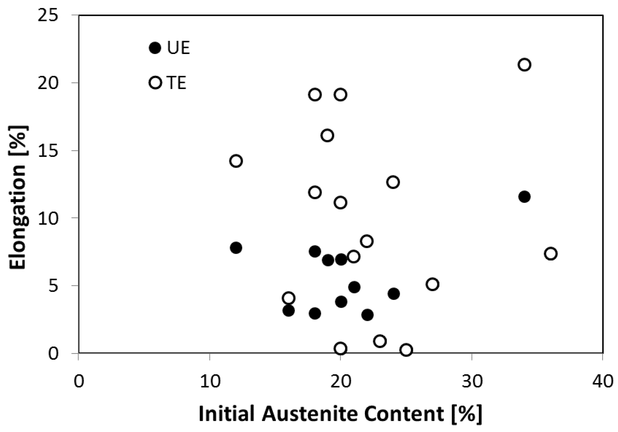
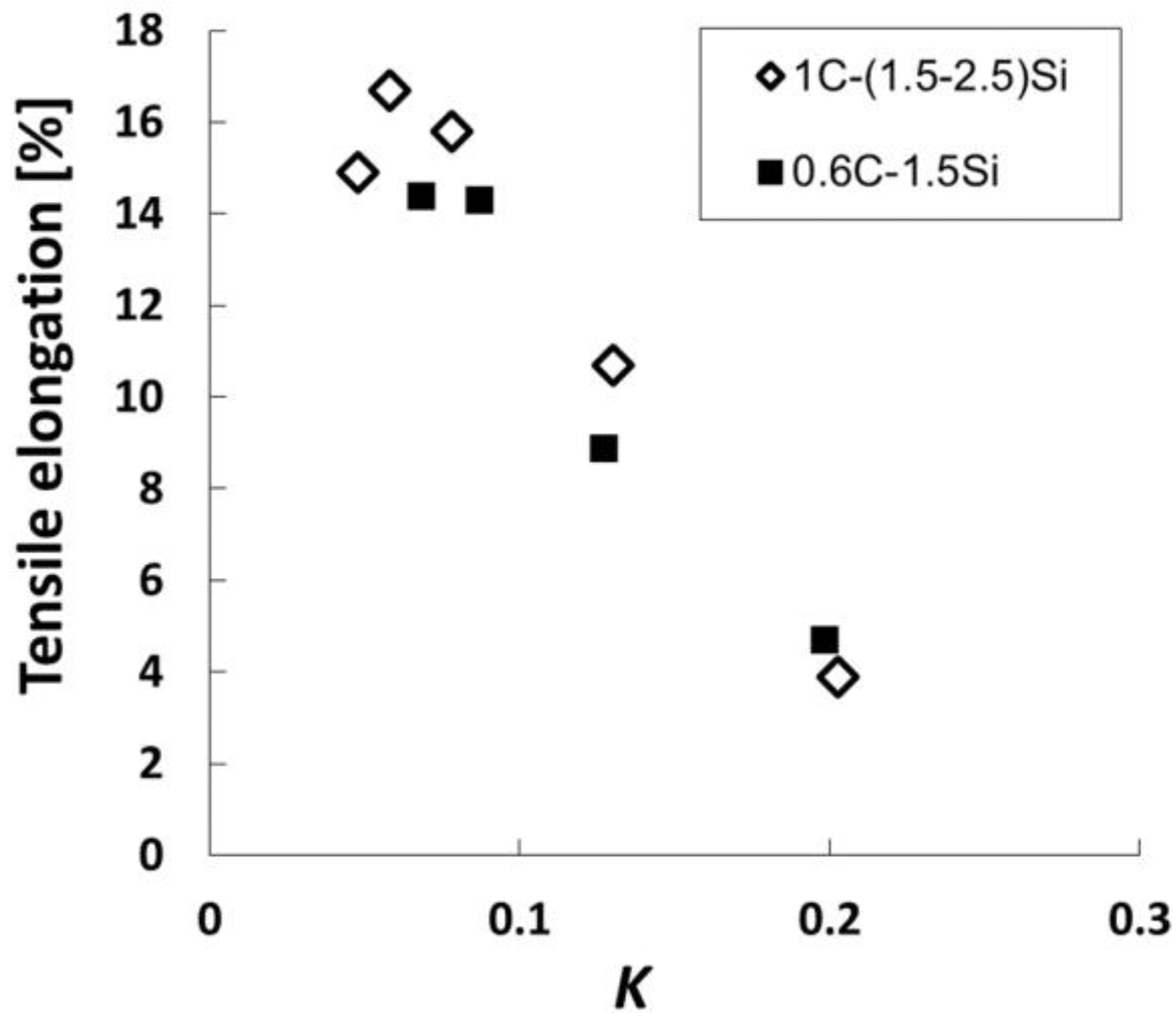
5. Ductility and Retained Austenite Content

Ultra-fine bainitic microstructures have been already analyzed as a function of the initial fraction of retained austenite, which was changed by altering the degree of isothermal bainitic transformation [56]. These results showed that increasing the initial austenite volume fraction up to an optimum value improves the uniform elongation towards the value of total elongation (which is also enhanced). Other studies on bainitic steels, in which the initial austenite volume fraction had been changed by tuning the bainitic transformation temperature, also resulted in the same trend: the higher the fraction of austenite, the higher the uniform and total elongations. In this case, the mechanical stability of the austenite resulted in being of little importance [63].
Studies on bainitic steels containing retained austenite revealed that an increase of the initial austenite content above an optimum value reduces the total elongation below the expected uniform elongation [56]. Results from reference [57] showed a total elongation proportional to the initial volume fraction of austenite in nanostructured bainite. In this case, fracture presumably takes place when the austenite content decreases down to a critical value, measured at fracture, close to 10% [64]. This value is thought to be the percolation limit, above which austenite maintains a continuous path through the test sample. It suggested that the formation of hard martensite cannot be tolerated if the austenite volume fraction decreases below the percolation limit, 10%, leading to fracture [64,65].
A recent work [9,42] on a large set of nanobainitic structures from different steels and heat treatments clearly revealed that there is no overall correlation between the initial austenite content and either the uniform elongation or the total elongation, Figure 8.
The possible existence of an optimum level of stability of austenite against mechanically induced martensitic transformation, in terms of ductility has also been studied. In one study, highly stable retained austenite resulted in being detrimental for the total elongation [57], whereas in another study, an increase of the austenite stability did contribute to enhance the ductility [9].
Given the lack of agreement on the effect of the mechanically-induced martensitic transformation on the ductility in nanostructured bainite, in a recent work [53,66] intended to elucidate it, the evolution of the retained austenite content, measured by means of XRD, was tracked as a function of the deformation after interrupted tensile tests (even beyond the uniform elongation) for different initial microstructures. It has been well established that the retained austenite fraction evolution with the plastic strain, ε, follows this exponential law [27,36,67,68]:
L n ( V F γ 0 ) L n ( V F γ ) = K ε
where ε is the true plastic strain at the uniform elongation region of the tensile test; V F γ 0 is the initial volume fraction of austenite at zero strain; VFγ is the volume fraction of austenite at a strain ε, and K is a fitting parameter that depends upon the material and the test temperature in the tensile test. This parameter K reflects the stability of the retained austenite: the higher the value, the greater the quantity of retained austenite is destabilized for a given increase in plastic strain.
Such an analysis was applied to the data obtained from interrupted tensile tests, performed at room temperature, in the mentioned work [53,66] where K was calculated for each condition using linear regression, see an example in Figure 9. In Figure 10, K values thus obtained and below 0.2 are plotted versus the tensile elongation of the corresponding sample, revealing that a reduced mechanically-induced martensitic transformation favors performance in terms of ductility. For values of K equal or higher than 0.2 (not plotted), this tendency disappeared, the elongation reaching a lower value, between 2% and 4%. In these cases, the presence of a brittle fracture was clear, the samples failing within the macroscopic uniform elongation, at their highest recorded stress. The concept of percolation limit failed to apply in that work, i.e., no lower limit of austenite content, below which crack propagation until fracture cannot be avoided, was found.
Results in Figure 10 are in good agreement with those given by another study [69] in which two samples subjected to interrupted tensile tests were analyzed by neutron diffraction. In the mentioned work, the two nanobainitic structures were obtained from the same alloy, after isothermal treatment each at a different temperature, 200 °C and 300 °C, whose duration was tailored in order to obtain the same initial austenite content, 35%. The sample treated at the highest temperature did not present mechanically-induced martensitic transformation, and its uniform elongation was outstanding, 10%, in comparison to the sample treated at 200 °C, which fractured at a plastic strain of 2%, Figure 11. For the low-ductility sample, the austenite content strongly decreased with deformation, which resulted in an important crystal texture formation, due to the high sensitivity of the martensitic transformation to the crystal orientation. The texture formation is illustrated in Figure 12, where the maximum and minimum values of the orientation distribution function (ODF) intensity are plotted as a function of the plastic strain. In the case of the high-ductility sample, the texture evolution, although lower, was not negligible. This fact revealed the occurrence of plastic crystal rotation of both austenite and bainitic ferrite, which suggests that this deformation mechanism can be behind the beneficial work-hardening behavior of the ductile samples, explained previously. That is, the martensitic transformation does not seem to be responsible of the rise of the incremental work-hardening exponent, n, that effectively delays the necking as was observed in Figure 6.
There is no doubt that the role of retained austenite is a topic of paramount concern. However, changes in the initial fraction of retained austenite and its stability cannot be easily made without altering other factors. In this sense, the coupling between plasticity and the mechanically induced transformation is complex, often without a clear distinction between cause and effect [70]. As already seen, there seems to be a correlation between plastic strain and the austenite fraction evolution, but it is not straightforward to know the extent at which the austenite evolution occurs as a consequence of the stress-strain behavior, or how instead this transformation affects the work hardening. In addition, Equation (3) is an empirical law which does not necessarily imply that the plastic deformation governs the austenite evolution, that is, stress-assisted martensitic transformation cannot be ruled out.
In the next section, stress-assisted conditions will be assumed, and experimental results on austenite evolution, considering the fraction and feature size/shape, will be discussed in terms of the mechanical partitioning between the phases of the composite.

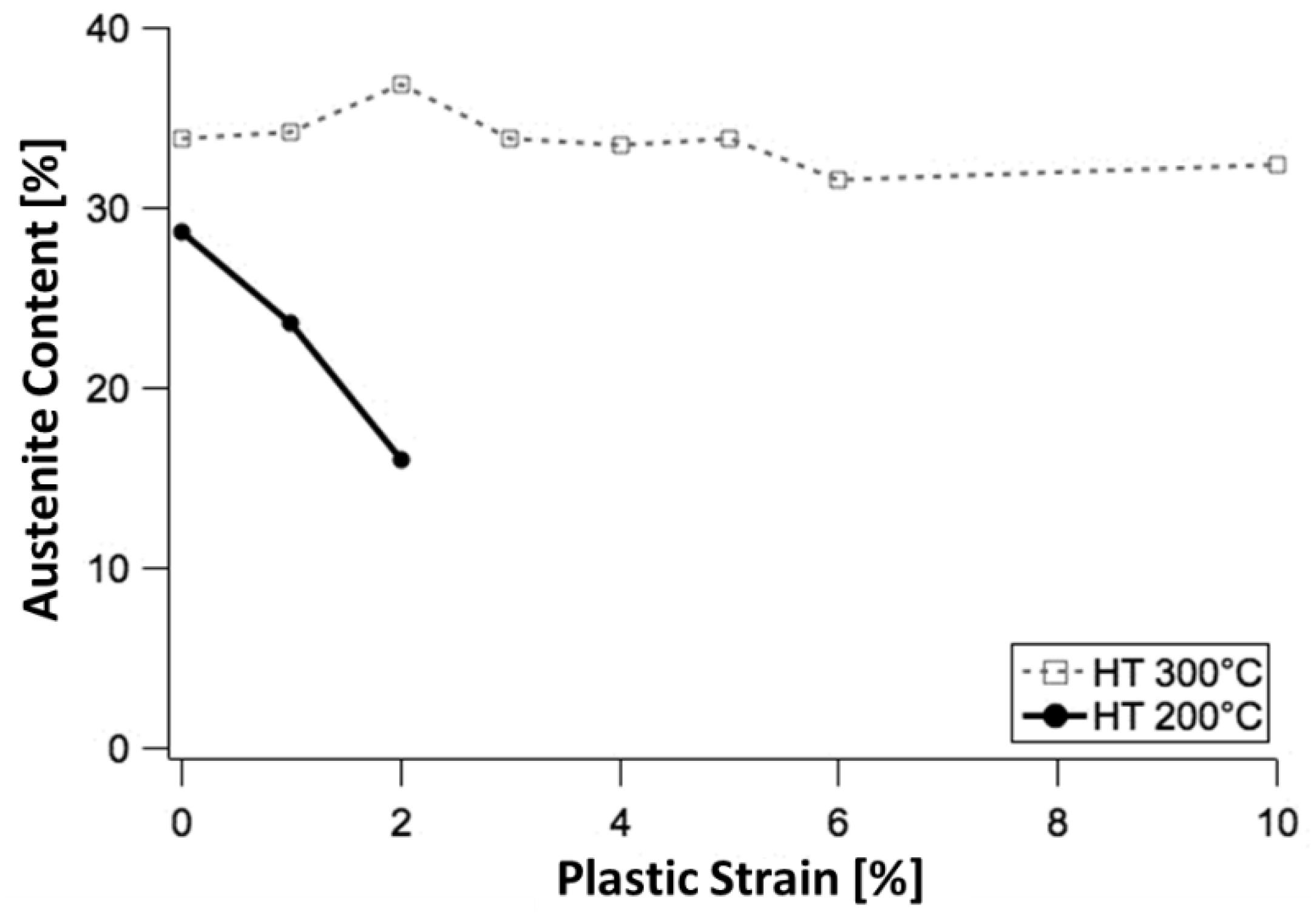
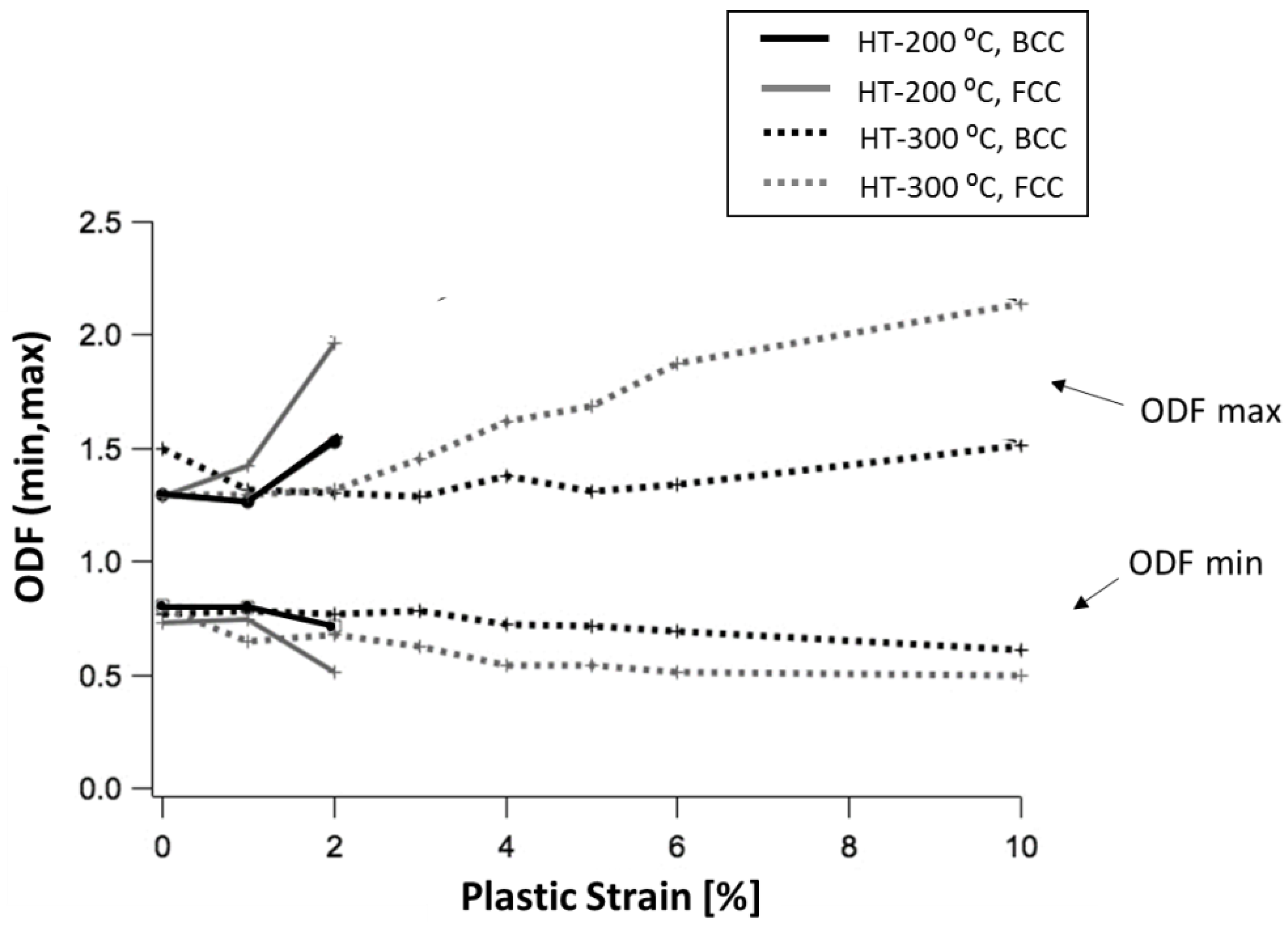
6. Retained Austenite Evolution and Mechanical Partitioning
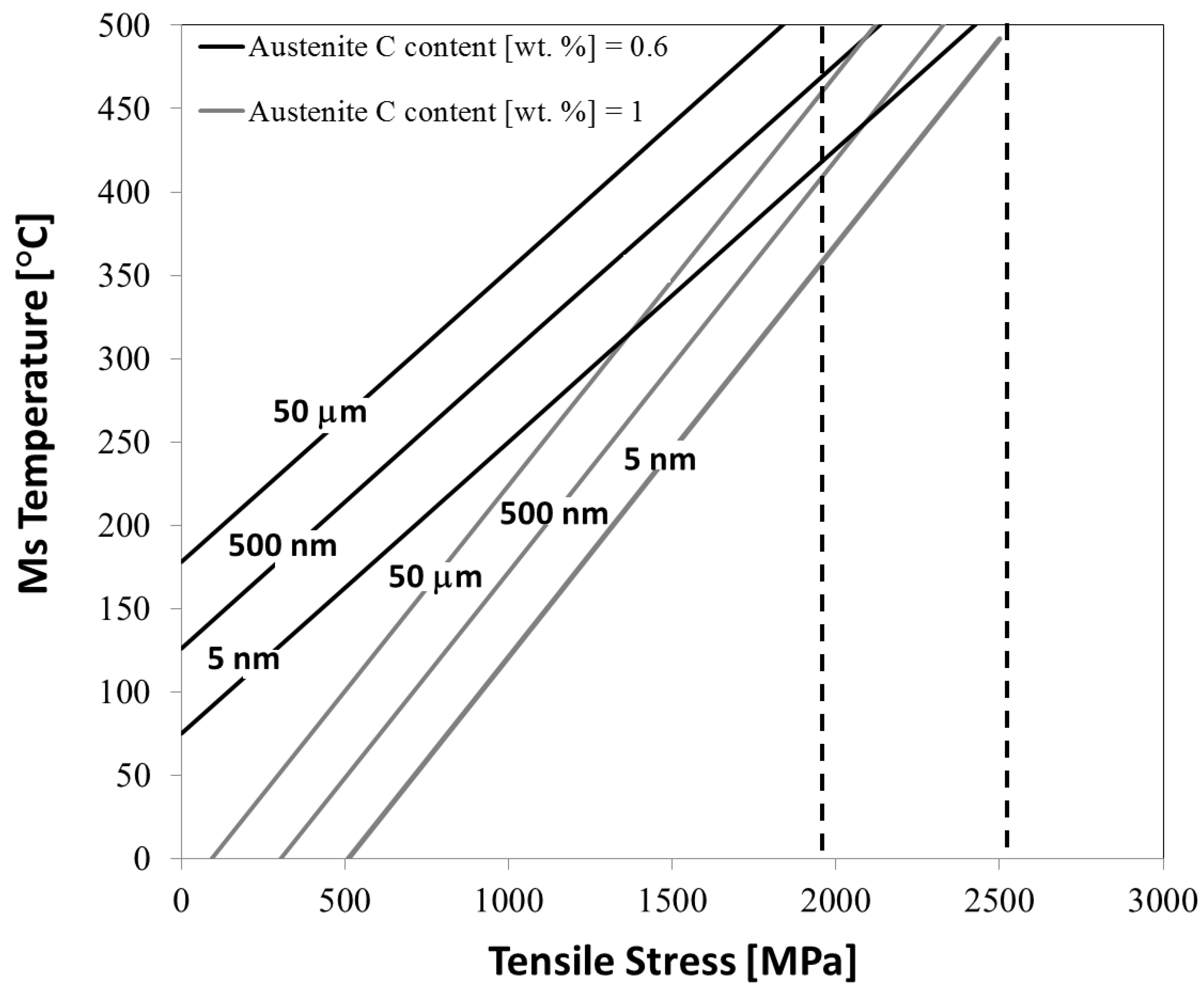
It is well known that martensitic transformation starts on cooling when the temperature gets below the Ms. The Ms is calculated as the temperature at which the following condition holds true:
Δ G γ   α < Δ G crit
where ΔGγ→α’ stands for the free energy change accompanying the martensitic transformation; and ΔGcrit is the minimum driving force needed to stimulate martensite by an athermal diffusionless nucleation and growth mechanism, which on cooling equals G N α [3,71].
Using the concept of Ms, the mechanically-induced martensitic transformation under stress-assisted conditions can be understood as a similar process. The effect of external stress is to increase Ms, by modifying ΔGγ→α’, which now includes a mechanical component. Therefore, the martensitic transformation begins in this case when the test-temperature is overcome by the growing Ms. It is possible to calculate the Ms temperature accounting for the effect of the applied stress, the orientation of the austenite crystal relative to the tensile direction, and also the parameters intrinsic to the austenite, i.e., its C content and size, following the methodology described in references [24,72]. In Figure 13, the straight lines indicate the Ms theoretical values as a function of the external mechanical tensile stress. The following conditions were assumed for the Ms calculation:
(1)
The most favorable orientation of the austenite crystal with the applied stress.
(2)
Two austenite C contents, 0.6 and 1 wt %. This covers a range of concentrations in good agreement with the values detected by XRD for the nanobainitic structures examined in the mentioned reference [54].
(3)
Δ G crit = G N α . This is the necessary condition for stress-assisted martensitic transformation, which represents its similarity to the martensitic transformation on cooling.
The results are in line with the effects just described: the smaller and richer-in-C the austenite is, the lower the Ms temperature, i.e., the more stable the austenite is. As for the applied stress, the tendency implies that increasing the applied stress raises the Ms temperature, facilitating the transformation of austenite into martensite, as explained.
In the work described in reference [54], nanostructured bainite was tensile tested until fracture and cross-sections from the tensile specimens were extracted for further examination through transmission electron microscopy (TEM), in order to detect remaining austenite features and/or mechanically formed martensite features. Each cross-section of the tensile specimens had a different level of deformation and had been subjected to a different maximum tensile stress value, contained within the range marked by the dashed lines in Figure 13. The high theoretical values of Ms for those stresses predicted total martensitic transformation, however, TEM examination revealed the presence of fine austenite features.
These results suggest that the mechanical partitioning, in this case stress partitioning, among the phases, cannot be neglected. The bainitic ferrite matrix seems to be playing an important role, by shielding the stress over the retained austenite. Therefore, it is inaccurate to assume that the retained austenite is subjected to the overall stress instead of a lower value.
The same idea of stress-partitioning is suggested by reference [73], after evaluation of the austenite fraction evolution with stress. In this work, the austenite content from different nanobainitic structures was measured by XRD after interrupted tensile tests, within the uniform elongation, and plotted against the corresponding true stress values. The austenite fraction evolution was modelled according to a modified version of the well-known Koistinen-Marburger law, using again the concept of Ms, but now by taking into account the polycrystalline nature of the material. For one of the steels, treated at two different temperatures, the results are shown in Figure 14. In all cases, the evolution of austenite as a function of stress is expected to take place at a higher or equal rate as it actually does, pointing again to a shielding effect by the bainitic ferrite. Moreover, when comparing samples from the same steel, treated at two transformation temperatures, the microstructures treated at the highest temperatures have a martensitic transformation behavior closer to theory, i.e., the austenite seems to withstand a stress value more similar to the macroscopically-measured true stress.

7. Mechanical Mismatch of Phases and Ductility

A general tendency observed on the effect of the heat treatment settings on the ductility of every steel is that the increase of the transformation temperature results in enhancement of the total elongation [53]. The duration of the isothermal holding, however, is not always beneficial. In some cases, the extension of the isothermal treatment beyond the purely necessary for the bainitic transformation, increased total elongation from a value of 7% to a value of 13%, even though no refinement of the austenite took place. In other cases, the ductility was found to slightly increase or even strongly decrease as the treatment was extended [53].
It has been suggested that a small mechanical mismatch between the phases in samples treated at high temperatures can be the reason behind improved ductility [54,73]. In other words, there seems to be, on one hand, a tendency to reduce the strength of the bainitic ferrite as the treatment temperature increases which can be justified by its lower C content and the decrease of defect content. On the other hand, the higher observed C content of retained austenite as the treatment temperature increases might contribute to enhance its strength, which becomes closer to the bainitic ferrite values or even exceed them. In order to confirm that possibility, local mechanical measurements in the phases present in the initial microstructure were performed by means of AFM (atomic force microscopy)-based nano-indentation, as shown in Figure 15 [15], where the phase indentation, either a plate of bainitic ferrite or an austenite feature, is clearly identified.
Results suggest that the possible differences in mechanical properties between bainitic ferrite and retained austenite dissipate if the steel has been treated at a temperature high enough, in this work, 350 °C. This important observation comes from the force values at which the loading curves start to diverge from the elastic regime, fitted to the Hertzian solution, Figure 16.

8. Conclusions

In nanostructured bainite the ductility is generally improved by increasing the bainitic treatment temperature. The total elongation of nanostructured bainite is enhanced by taking advantage of two phenomena: moderate work-hardening (measured as the incremental work-hardening rate) and higher damage resistance. In samples presenting lower values of ductility, however, high stresses trigger brittle fracture of the material even long before plastic instability is predicted. In some positive cases, the increase of the incremental work-hardening rate at the latter stages of the uniform deformation region increases the uniform elongation by delay of the necking formation.
According to the latest works, there is no correlation between the initial volume fraction of austenite and the ductility. However, a large amount of unstable austenite is not appropriate in terms of total elongation. Instead, a highly stable austenite, unable to undergo mechanically-induced martensitic transformation, or implying a low rate of this transformation, is more beneficial.
The reduction of the mechanical mismatch between austenite and bainitic ferrite seems to be the reason behind the better performance of samples treated at higher temperature, i.e., a more C-enriched retained austenite embedded in a more recovered bainitic ferrite can minimize the mechanical partitioning between these phases, leading to enhanced ductility.

Acknowledgments

The authors gratefully acknowledge the support of the European Research Fund for Coal and Steel, the Spanish Ministry of Economy and Competitiveness and the Fondo Europeo de Desarrollo Regional (FEDER) for partially funding this research under the contracts RFSR-CT-2012-00017, RFSR-CT-2014-00016 and MAT2013-47460-C5-1−P, respectively.

Conflicts of Interest

The authors declare no conflict of interest.

References

  1. Raabe, D.; Ponge, D.; Dmitrieva, O.; Sander, B. Nanoprecipitate-hardened 1.5 GPa steels with unexpected high ductility. Scr. Mater. 2009, 60, 1141–1144. [Google Scholar] [CrossRef]
  2. Raabe, D. Maraging Steels and Maraging TRIP Steels. Avaliable online: http://www.dierk-raabe.com/martensite-alloys-and-transformations/maraging-trip-steels/ (accessed on 28 November 2016).
  3. Bhadeshia, H.K.D.H. Bainite in Steels, 2nd ed.; Institute of Materials, Maney Publishing: London, UK, 2001. [Google Scholar]
  4. Timokhina, I.B.; Beladi, H.; Xiong, X.Y.; Adachi, Y.; Hodgson, P.D. Nanoscale microstructural characterization of a nanobainitic steel. Acta Mater. 2011, 59, 5511–5522. [Google Scholar] [CrossRef]
  5. Caballero, F.G.; Bhadeshia, H.K.D.H. Very strong bainite. Curr. Opin. Solid State Mater. Sci. 2004, 8, 251–257. [Google Scholar] [CrossRef]
  6. Yang, J.; Wang, T.S.; Zhang, B.; Zhang, F.C. Microstructure and mechanical properties of high-carbon Si-Al-rich steel by low-temperature austempering. Mater. Des. 2012, 35, 170–174. [Google Scholar] [CrossRef]
  7. Bhadeshia, H.K.D.H. Nanostructured bainite. Proc. R. Soc. A Math. Phys. Eng. Sci. 2010, 466, 3–18. [Google Scholar] [CrossRef]
  8. Sourmail, T.; Caballero, F.G.; Garcia-Mateo, C.; Smanio, V.; Ziegler, C.; Kuntz, M.; Elvira, R.; Leiro, A.; Vuorinen, E.; Teeri, T. Evaluation of potential of high Si high C steel nanostructured bainite for wear and fatigue applications. Mater. Sci. Technol. 2013, 29, 1166–1173. [Google Scholar] [CrossRef]
  9. Garcia-Mateo, C.; Caballero, F.G.; Sourmail, T.; Kuntz, M.; Cornide, J.; Smanio, V.; Elvira, R. Tensile behaviour of a nanocrystalline bainitic steel containing 3 wt. % silicon. Mater. Sci. Eng. A 2012, 549, 185–192. [Google Scholar] [CrossRef] [Green Version]
  10. Garcia-Mateo, C.; Caballero, F.G. Ultra-high-strength bainitic steels. ISIJ Int. 2005, 45, 1736–1740. [Google Scholar] [CrossRef]
  11. Caballero, F.G.; Bhadeshia, H.K.D.H.; Mawella, K.J.A.; Jones, D.G.; Brown, P. Very strong low temperature bainite. Mater. Sci. Technol. 2002, 18, 279–284. [Google Scholar] [CrossRef] [Green Version]
  12. Caballero, F.G.; Miller, M.K.; Garcia-Mateo, C.; Cornide, J. New experimental evidence of the diffusionless transformation nature of bainite. J. Alloy. Compd. 2013, 577, S626–S630. [Google Scholar] [CrossRef]
  13. Bhadeshia, H.K.D.H. Bainite in silicon steels: New composition-property approach. Part 2. Met. Sci. 1983, 17, 420–425. [Google Scholar] [CrossRef]
  14. Bhadeshia, H.K.D.H.; Edmonds, D.V. Bainite in silicon steels: New composition-property approach. Part 1. Met. Sci. 1983, 17, 411–419. [Google Scholar] [CrossRef]
  15. Morales-Rivas, L.; Gonzalez-Orive, A.; Garcia-Mateo, C.; Hernandez-Creus, A.; Caballero, F.G.; Vazquez, L. Nanomechanical characterization of nanostructured bainitic steel: Peak force microscopy and nanoindentation with afm. Sci. Rep. 2015, 5. [Google Scholar] [CrossRef] [PubMed]
  16. Garcia-Mateo, C.; Jimenez, J.A.; Yen, H.W.; Miller, M.K.; Morales-Rivas, L.; Kuntz, M.; Ringer, S.P.; Yang, J.R.; Caballero, F.G. Low temperature bainitic ferrite: Evidence of carbon super-saturation and tetragonality. Acta Mater. 2015, 91, 162–173. [Google Scholar] [CrossRef]
  17. Cohen, M. The strengthening of steel. Trans. Metall. AIME 1962, 224, 638–657. [Google Scholar]
  18. Christian, J.W. Tetragonal martensites in ferrous alloys—A critique. Mater. Trans. JIM 1992, 33, 208–214. [Google Scholar] [CrossRef]
  19. Caballero, F.; Miller, M.; Garcia-Mateo, C.; Capdevila, C.; Babu, S. Redistribution of alloying elements during tempering of a nanocrystalline steel. Acta Mater. 2008, 56, 188–199. [Google Scholar] [CrossRef]
  20. Caballero, F.G.; Miller, M.K.; Clarke, A.J.; Garcia-Mateo, C. Examination of carbon partitioning into austenite during tempering of bainite. Scr. Mater. 2010, 63, 442–445. [Google Scholar] [CrossRef]
  21. Wilde, J.; Cerezo, A.; Smith, G.D.W. Three-dimensional atomic-scale mapping of a Cottrell atmosphere around a dislocation in iron. Scr. Mater. 2000, 43, 39–48. [Google Scholar] [CrossRef]
  22. Cornide, J.; Garcia-Mateo, C.; Capdevila, C.; Caballero, F.G. An assessment of the contributing factors to the nanoscale structural refinement of advanced bainitic steels. J. Alloy. Compd. 2013, 577, S43–S47. [Google Scholar] [CrossRef]
  23. Haidemenopoulos, G.N.; Grujicic, M.; Olson, G.B.; Cohen, M. Transformation microyielding of retained austenite. Acta Metall. 1989, 37, 1677–1682. [Google Scholar] [CrossRef]
  24. Chatterjee, S.; Bhadeshia, H. Transformation induced plasticity assisted steels: Stress or strain affected martensitic transformation. Mater. Sci. Technol. 2007, 23, 1101–1104. [Google Scholar] [CrossRef]
  25. Morales-Rivas, L.; Caballero, F.G.; Garcia-Mateo, C. Retained austenite: Stability in a nanostructured bainitic steel. In Encyclopedia of Iron, Steel and Their Alloys; Rafael Colás, G.E.T., Ed.; CRC Press: Cleveland, OH, USA, 2016; Available online: http://www.crcnetbase.com/doi/abs/10.1081/E-EISA-120051968 (accessed on 30 November 2016).
  26. Garcia-Mateo, C.; Caballero, F.G.; Miller, M.K.; Jimenez, J.A. On measurement of carbon content in retained austenite in a nanostructured bainitic steel. J. Mater. Sci. 2012, 47, 1004–1010. [Google Scholar] [CrossRef]
  27. Sherif, M.Y.; Mateo, C.G.; Sourmail, T.; Bhadeshia, H.K.D.H. Stability of retained austenite in trip-assisted steels. Mater. Sci. Technol. 2004, 20, 319–322. [Google Scholar] [CrossRef]
  28. Garcia-Mateo, C.; Caballero, F.G.; Chao, J.; Capdevila, C.; de Andres, C.G. Mechanical stability of retained austenite during plastic deformation of super high strength carbide free bainitic steels. J. Mater. Sci. 2009, 44, 4617–4624. [Google Scholar] [CrossRef]
  29. Yang, H.-S.; Bhadeshia, H.K.D.H. Austenite grain size and the martensite-start temperature. Scr. Mater. 2009, 60, 493–495. [Google Scholar] [CrossRef]
  30. Sadeghpour, S.; Kermanpur, A.; Najafizadeh, A. Investigation of the effect of grain size on the strain-induced martensitic transformation in a high-Mn stainless steel using nanoindentation. Mater. Sci. Eng. A 2014, 612, 214–216. [Google Scholar] [CrossRef]
  31. García-Junceda, A.; Capdevila, C.; Caballero, F.G.; de Andrés, C.G. Dependence of martensite start temperature on fine austenite grain size. Scr. Mater. 2008, 58, 134–137. [Google Scholar] [CrossRef]
  32. Brandt, M.L.; Olson, G.B. Bainitic stabilization of austenite in low alloy sheet steels. Iron Steel Soc. AIME 1993, 20, 55–60. [Google Scholar]
  33. Jacques, P.J.; Furnémont, Q.; Lani, F.; Pardoen, T.; Delannay, F. Multiscale mechanics of trip-assisted multiphase steels: I. Characterization and mechanical testing. Acta Mater. 2007, 55, 3681–3693. [Google Scholar] [CrossRef]
  34. Ryu, J.H.; Kim, D.-I.; Kim, H.S.; Bhadeshia, H.K.D.H.; Suh, D.-W. Strain partitioning and mechanical stability of retained austenite. Scr. Mater. 2010, 63, 297–299. [Google Scholar] [CrossRef]
  35. Timokhina, I.B.; Hodgson, P.D.; Pereloma, E.V. Effect of microstructure on the stability of retained austenite in transformation-induced-plasticity steels. Metall. Mater. Trans. A 2004, 35, 2331–2341. [Google Scholar] [CrossRef]
  36. Jacques, P.J.; Ladrière, J.; Delannay, F. On the influence of interactions between phases on the mechanical stability of retained austenite in transformation-induced plasticity multiphase steels. Metall. Mater. Trans. A 2001, 32, 2759–2768. [Google Scholar] [CrossRef]
  37. Avishan, B.; Garcia-Mateo, C.; Morales-Rivas, L.; Yazdani, S.; Caballero, F.G. Strengthening and mechanical stability mechanisms in nanostructured bainite. J. Mater. Sci. 2013, 48, 6121–6132. [Google Scholar] [CrossRef]
  38. Young, C.H.; Bhadeshia, H.K.D.H. Strength of mixtures of bainite and martensite. Mater. Sci. Technol. 1994, 10, 209–214. [Google Scholar] [CrossRef]
  39. Young, C.H.; Bhadeshia, H.K.D.H. Computer modelling for the yield strength of the mixed micro-structures of bainite and martensite. J. Phys. IV 1995, 5, 267. [Google Scholar] [CrossRef]
  40. Caballero, F.G.; García-Mateo, C.; Capdevila, C.; de Andrés, C.G. Advanced Ultrahigh Strength Bainitic Steels. Mater. Manuf. Process. 2007, 22, 502–506. [Google Scholar] [CrossRef] [Green Version]
  41. Singh, S.B.; Bhadeshia, H.K.D.H. Estimation of bainite plate-thickness in low-alloy steels. Mater. Sci. Eng. A 1998, 245, 72–79. [Google Scholar] [CrossRef]
  42. Garcia-Mateo, C.; Sourmail, T.; Caballero, F.G.; Smanio, V.; Kuntz, M.; Ziegler, C.; Leiro, A.; Vuorinen, E.; Elvira, R.; Teeri, T. Nanostructured steel industrialisation: Plausible reality. Mater. Sci. Technol. 2014, 30, 1071–1078. [Google Scholar] [CrossRef]
  43. Chang, L.C.; Bhadeshia, H.K.D.H. Austenite films in bainitic microstructures. Mater. Sci. Technol. 1995, 11, 105–108. [Google Scholar] [CrossRef]
  44. Underwood, E.E. Quantitative Microscopy; McGraw-Hill: New York, NY, USA, 1968; Volume 78. [Google Scholar]
  45. Lan, H.-F.; Liu, X.-H.; Du, L.-X. Ultra-hard bainitic steels processed through low temperature heat treatment. Adv. Mater Res. 2011, 156–157, 1708–1712. [Google Scholar] [CrossRef]
  46. Wang, M.M.; Tasan, C.C.; Ponge, D.; Dippel, A.C.; Raabe, D. Nanolaminate transformation-induced plasticity-twinning-induced plasticity steel with dynamic strain partitioning and enhanced damage resistance. Acta Mater. 2015, 85, 216–228. [Google Scholar] [CrossRef]
  47. Jacques, P.J. Transformation-induced plasticity for high strength formable steels. Curr. Opin. Solid State Mater. Sci. 2004, 8, 259–265. [Google Scholar] [CrossRef]
  48. Ludwigson, D.C.; Berger, J.A. Plastic behaviour of metastable austenitic stainless steels. J. Iron Steel Inst. 1969, 207, 63–69. [Google Scholar]
  49. Jacques, P.J.; Girault, E.; Harlet, Ph.; Delanny, F. The developments of cold-rolled trip-assisted multiphase steels. Low silicon trip-assisted multiphase steels. ISIJ Int. 2001, 41, 1061–1067. [Google Scholar] [CrossRef]
  50. Jacques, P.J.; Furnemont, Q.; Mertens, A.; Delanny, F. On the sources of work hardening by transformation-induced plasticity. Philos. Mag. 2001, 81, 1789–1812. [Google Scholar] [CrossRef]
  51. Deep, G.; Williams, W.M. Isothermic annealing of bainite. Can. Metall. Q 1975, 14, 85–96. [Google Scholar] [CrossRef]
  52. Papaefthymiou, S. Failure Mechanisms of Multiphase Steels. Ph.D. Thesis, Rheinisch-Westfälische Technische Hochschule Aachen (RWTH) (Aachen University), Aachen, Germany, 2005. [Google Scholar]
  53. Sourmail, T.; Galtier, A.; Sanz, R.P.; Janisch, R.; Sampath, S.; Müller, I.; Kerscher, E.; Rementeria, R.; Garcia-Mateo, C.; Caballero, F.G.; et al. Understanding Basic Mechanism to Optimize and Predict in Service Properties of Nanobainitic Steels (Mecbain). Final Report.; Reference RFSR-CT-2012-00017; European Commission: Luxembourg, 2017; in press. [Google Scholar]
  54. Morales-Rivas, L.; Yen, H.W.; Huang, B.M.; Kuntz, M.; Caballero, F.G.; Yang, J.R.; Garcia-Mateo, C. Tensile response of two nanoscale bainite composite-like structures. JOM 2015, 67, 2223–2235. [Google Scholar] [CrossRef]
  55. Chatterjee, S.; Bhadeshia, H. Trip-assisted steels: Cracking of high-carbon martensite. Mater. Sci. Technol. 2006, 22, 645–649. [Google Scholar] [CrossRef]
  56. Sandvik, B.P.J.; Nevalainen, H.P. Structure-property relationships in commercial low-alloy bainitic-austenitic steel with high-strength, ductility, and toughness. Met. Technol. 1981, 8, 213–220. [Google Scholar] [CrossRef]
  57. Garcia-Mateo, C.; Caballero, F.G. The role of retained austenite on tensile properties of steels with bainitic microstructures. Mater. Trans. JIM 2005, 46, 1839–1846. [Google Scholar] [CrossRef]
  58. Knijf, D.D. Influence of Quenching and Partitioning Parameters on the Microstructure and Mechanical Properties of Advanced High Strength Steels. Ph.D. Thesis, Faculteit Ingenieurswetenschappen (Ghent University), Ghent, Belgium, June 2015. [Google Scholar]
  59. McCoy, R.A.; Gerberich, W.W. Hydrogen embrittlement studies of a trip steel. Metall. Trans. 1973, 4, 539–547. [Google Scholar] [CrossRef]
  60. Hirth, J.P. Effects of hydrogen on the properties of iron and steel. Metall. Trans. 2005, 52, 1223–1228. [Google Scholar] [CrossRef]
  61. Ronevich, J.A.; Speer, J.G.; Matlock, D.K. Hydrogen embrittlement of commercially produced advanced high strength sheet steels. SAE Int. J. Mater. Manuf. 2010, 3, 255–267. [Google Scholar] [CrossRef]
  62. Ryu, J.H. Hydrogen Embrittlement in Trip and Twip Steels. Ph.D. Thesis, Pohang University of Science and Technology, Pohang, Korea, 2012. [Google Scholar]
  63. Miihkinen, V.T.T.; Edmonds, D.V. Tensile deformation of two experimental high-strength bainitic low-alloy steels containing silicon. Mater. Sci. Technol. 1987, 3, 432–440. [Google Scholar] [CrossRef]
  64. Bhadeshia, H.K.D.H. The dimensions of steel. Ironmak. Steelmak. 2007, 34, 194–199. [Google Scholar] [CrossRef]
  65. Sherif, M.Y. Characterisation and Development of Nanostructured, Ultrahigh Strength, and Ductile Bainitic Steels. Ph.D. Thesis, University of Cambridge, Cambridge, UK, 2006. [Google Scholar]
  66. Sourmail, T.; Garcia-Mateo, C.; Caballero, F.G.; Morales-Rivas, L.; Rementeria, R.; Kuntz, M. Tensile ductility of nanostructured bainitic steels: Influence of retained austenite stability. Mater. Sci. Eng. A 2016. submitted for publication. [Google Scholar]
  67. Sugimoto, K.; Kobayashi, M.; Hashimoto, S. Ductility and strain-induced transformation in a high-strength transformation-induced plasticity-aided dual-phase steel. Metall. Trans. A 1992, 23, 3085–3091. [Google Scholar] [CrossRef]
  68. Pyshmintev, I.Y.; de Meyer, M.; de CooMan, B.C.; Savray, R.A.; Shveykin, V.P.; VerMelen, M. The influence of the stress state on the plasticity of transformation induced plasticity-aided steel. Metall. Mater. Trans. A 2002, 33A, 16591667. [Google Scholar]
  69. Babu, S.S.; Vogel, S.; Garcia-Mateo, C.; Clausen, B.; Morales-Rivas, L.; Caballero, F.G. Microstructure evolution during tensile deformation of a nanostructured bainitic steel. Scr. Mater. 2013, 69, 777–780. [Google Scholar] [CrossRef]
  70. Shi, J.; Turteltaub, S.; Giessen, E.V.D. Analysis of grain size effects on transformation-induced plasticity based on a discrete dislocation-transformation model. J. Mech. Phys. Solids 2010, 58, 1863–1878. [Google Scholar] [CrossRef]
  71. Ghosh, G.; Olson, G.B. Kinetics of fcc → bcc heterogeneous martensitic nucleation—II. Thermal activation. Acta Metall. Mater. 1994, 42, 3371–3379. [Google Scholar] [CrossRef]
  72. Yang, H.S.; Suh, D.W.; Bhadeshia, H. More Complete Theory for the Calculation of the Martensite-Start Temperature in Steels. ISIJ Int. 2012, 52, 164–166. [Google Scholar] [CrossRef]
  73. Morales-Rivas, L.; Garcia-Mateo, C.; Kuntz, M.; Sourmail, T.; Caballero, F.G. Induced martensitic transformation during tensile test in nanostructured bainitic steels. Mater. Sci. Eng. A 2016, 662, 169–177. [Google Scholar] [CrossRef]
Figure 1. Secondary-electron scanning electron micrographs (SE-SEM) of two nanostructured bainites from the same steel, with chemical composition in reference [15], treated at 250 °C (a) and 350 °C (b). γ stands for austenite, and α PT, for bainitic ferrite plate thickness.
Metals 06 00302 g001
Figure 2. Engineering tensile strain-stress curves of two nanostructured bainite samples from different steels, both containing 1C–1.5Si wt %, but steel in (a) having 2Mn wt % and steel in (b) having 0.9Mn–2.6Ni wt % instead. Adapted from reference [37].
Metals 06 00302 g002
Figure 3. Ultimate tensile strength (UTS) and yield strength (YS) of different nanostructured bainites as a function of the ratio Vα/tα. Adapted from reference [42].
Metals 06 00302 g003
Figure 4. Two examples of the tensile response of two typical transformation induced plasticity (TRIP) aided steels and their corresponding austenite fraction evolution. Adapted from reference [47].
Metals 06 00302 g004
Figure 5. Correlation between strength and elongation (TE, total elongation; and UE, uniform elongation) parameters of different nanostructured bainites, from data from reference [53]. (a) UE vs. the ratio between ultimate tensile strength and yield strength; (b) elongation (TE and UE) vs. yield strength; (c) elongation (TE and UE) vs. ultimate tensile strength; (d) TE vs. the product between TE and ultimate tensile strength.
Metals 06 00302 g005
Figure 6. Evolution of the incremental work-hardening exponent, n, as a function of the true plastic strain, of three nanobainitic structures treated from the same steel treated at three different temperatures, 200, 250, and 300 °C. Adapted from reference [57].
Metals 06 00302 g006
Figure 7. Fracture surface of tensile specimens of two nanobainitic structures of the same steel [54], treated at 250 °C (a); detail of the crack initiation site in (b); and treated at 220 °C (c).
Metals 06 00302 g007
Figure 8. Values of total and uniform elongation, TE and UE, respectively, vs. the initial austenite content. Adapted from reference [9,42].
Metals 06 00302 g008
Figure 9. Evolution of the content of transformed retained austenite for the same steel subjected to different heat treatments: bainitic treatment at 220 °C or at 250 °C. The slope of the lines is K, the fitting parameter of Equation (3). Adapted from references [53,66].
Metals 06 00302 g009
Figure 10. Tensile elongation vs. K, the fitting parameter of Equation (3), for different nanobainitic structures, from steel containing 0.6 and 1 C wt %. Adapted from references [53,66].
Metals 06 00302 g010
Figure 11. Evolution of austenite content, measured by neutron diffraction, as a function of the plastic strain during a tensile test, for two nanobainitic structures from the same steel after customized isothermal treatments at 200 and 300 °C. Adapted from reference [69].
Metals 06 00302 g011
Figure 12. Evolution of the minimum and maximum orientation distribution function (ODF) intensity values of bcc (bct) and fcc phases, analysed by neutron diffraction, as a function of the plastic strain during a tensile test, for two nanobainitic structures from the same steel after customized isothermal treatments at 200 and 300 °C. Adapted from reference [69].
Metals 06 00302 g012
Figure 13. Theoretical values of Ms (solid lines) as a function of the retained austenite C content, the austenite feature size, and the overall tensile stress, for the steel described in reference [54]. The dashed lines delimit the experimental tensile stresses over the TEM-analyzed cross sections. Adapted from reference [54].
Metals 06 00302 g013
Figure 14. Experimental results (solid symbols) for the martensite content evolution as a function of the true stress of tensile test, and predicted values (dotted lines) according to the procedure mentioned in the main text, for two nanobainitic structures from one steel treated at 220 and 250 °C. Adapted from reference [73].
Metals 06 00302 g014
Figure 15. Atomic force microscopy (AFM) image showing previously performed indentations in either bainitic ferrite or austenite, in a nanobainitic structure treated at 300 °C, described in reference [15].
Metals 06 00302 g015
Figure 16. Approach force curves obtained by AFM-based nano-indentation in either bainitic ferrite or austenite, in a nanobainitic structure treated at 300 °C, described in reference [15].
Metals 06 00302 g016

