Article

Fretting Behavior of SPR Joining Dissimilar Sheets of Titanium and Copper Alloys

Innovative Manufacturing Research Centre, Kunming University of Science and Technology, Kunming 650500, China
*
Author to whom correspondence should be addressed.
Metals 2016, 6(12), 312; https://doi.org/10.3390/met6120312
Submission received: 18 October 2016 / Revised: 2 December 2016 / Accepted: 2 December 2016 / Published: 9 December 2016
(This article belongs to the Special Issue Titanium Alloys 2017)

Abstract

:
The fretting performance of self-piercing riveting joining dissimilar sheets in TA1 titanium alloy and H62 copper alloy was studied in this paper. Load-controlled cyclic fatigue tests were carried out using a sine waveform and in tension-tension mode. Scanning electron microscopy and energy-dispersive X-ray techniques were employed to analyze the fretting failure mechanisms of the joints. The experimental results showed that there was extremely severe fretting at the contact interfaces of rivet and sheet materials for the joints at relatively high loads levels. Moreover, the severe fretting in the region on the locked sheet in contact with the rivet was the major cause of the broken locked sheet for the joints at low load level.

1. Introduction

Facing a decreasing amount of resources, lightweight design principles continue to prosper rapidly in different engineering fields. As a result, lightweight materials for different applications have been developed. Fusion welding and friction stir welding techniques are normally used to join lightweight metal sheets [1,2]. However, it is not easy to weld dissimilar metal sheets due to the formation of intermetallic phases. Self-piercing riveting (SPR) is a new high-speed mechanical fastening technique suitable for point-joining advanced lightweight sheet materials that are dissimilar, coated, and hard to weld [3].
In the past few years, the mechanical properties of SPR joints and the SPR technique itself have been studied by many scholars. Kang et al. [4] aimed to evaluate the static and fatigue strengths of the joints using coach-peel, cross-tension and tensile-shear specimens with experimental tests and numerical analysis. Su et al. [5] investigated the fracture and fatigue behaviors of SPR and clinch joints in lap-shear specimens of 6111-T4 aluminum sheets based on experimental observations, and examined the optical micrographs of both types of joints before and after failure under quasi-static and cyclic loading conditions. Calabrese et al. [6] conducted a long-time salt spray corrosion test for steel/aluminum hybrid joints obtained by SPR technique to evaluate the mechanical degradation in these critical environmental conditions. The influence of resistance heating on dissimilar SPR joints with unequal thickness was studied systematically by Lou et al. [7]. They reported that SPR joints using rivet-welding could obtain higher tensile-shear strength than with conventional SPR joints. Haque et al. [8] developed a simple geometrical method to calculate rivet flaring without having to cross-section a joint. It is a nondestructive testing method to determine rivet flaring based on the characteristic force-displacement curve, and could be a very useful tool in joint product development and process optimization.
A newly developed solid state joining technique—friction self-piercing riveting (F-SPR)—has been applied for joining high strength aluminum alloy to magnesium alloy [9,10]. The process was performed on a specially designed machine where the spindle can achieve a sudden stop. The effects of rivet rotating rate and punch speed on axial plunge force, torque, joint microstructure, and quality were analyzed systematically. A 3-D thermo-mechanical finite-element (FE) model of F-SPR process was developed using an LS-DYNA code [11]. Temperature-dependent material parameters were utilized to calculate the material yield and flow in the joint formation. A preset crack failure method was used to model the material failure of the top sheet. The calculated joint geometry exhibited a good agreement with the experimental measurement.
In a recent study, Haque and Durandet [12] described a parametric study of the mechanical behavior of SPR joints of steel sheets in two loading conditions (lap-shear and cross-tension). An empirical model was developed to predict the joint strength in cross-tension loading using characteristic joint data determined directly from the SPR process (force-displacement) curve. The tensile and fatigue behavior of SPR in carbon fiber reinforced plastic (CFRP) to aluminum 6111 T82 alloys were evaluated by Kang et al. [13]. The SPR lap-shear joints under fatigue loads failed predominantly due to kinked crack growth along the width of the bottom aluminum sheet. The fatigue cracks initiated in the plastically deformed region of the aluminum sheet close to the rivet shank in the rivet–sheet interlock region. Mucha and Witkowski [14] discussed the strength of riveted joints of various sheet materials: DC01 steel, AW-5754 aluminum alloy, and their hybrid arrangements. The fracture mechanism of riveted joints in unilateral tensile tests of T-shaped specimens made of various sheet materials was also analyzed. Chung and Kim [15] investigated the fatigue strength of SPR joints in tensile-shear specimens with dissimilar Al-5052 and steel sheets. A structural analysis of the specimen was conducted. For this specimen, the upper steel sheet with stood applied load in a monotonic test and played a major role in the low-cycle region. In the high-cycle region, however, the harder surface of the upper steel sheet reduced the fatigue strength by enhancing fretting crack initiation on the opposite softer aluminum surface.
Titanium alloy sheets and copper alloy sheets have been widely used in different engineering fields due to excellent strength, ductility, and corrosion resistance. However, it is not easy to weld titanium sheets with copper alloys, as their melting points and thermal conductivity are very different. It is widely accepted that dissimilar metal sheets of titanium with copper alloys can be jointed well by SPR. In a previous paper by He et al. [16], the static strength of SPR joints in dissimilar sheets of titanium and copper alloys was studied. However, no investigation on fretting behavior of such SPR joints has been reported so far.
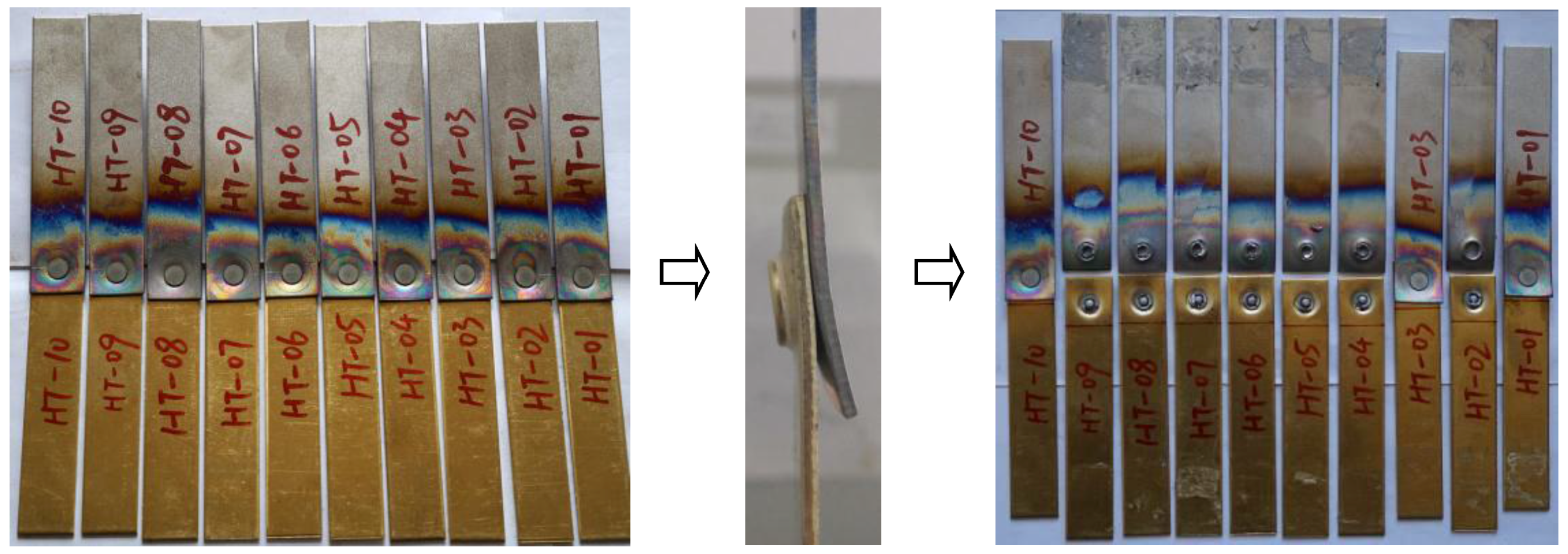
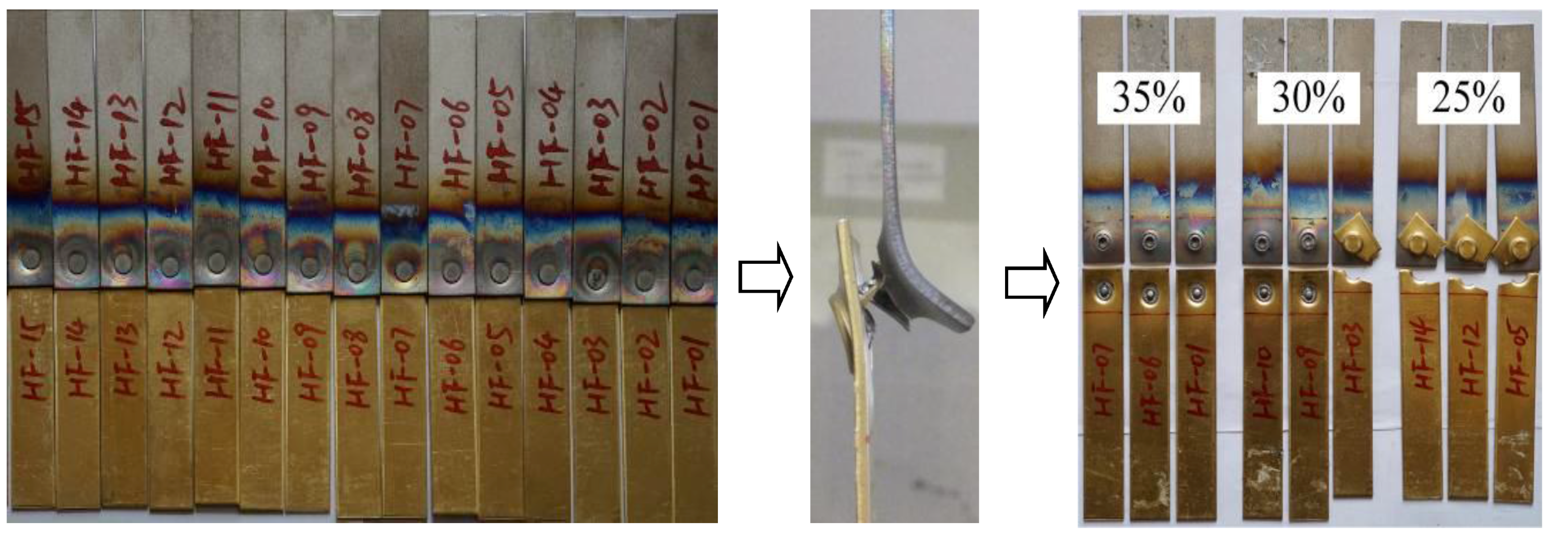
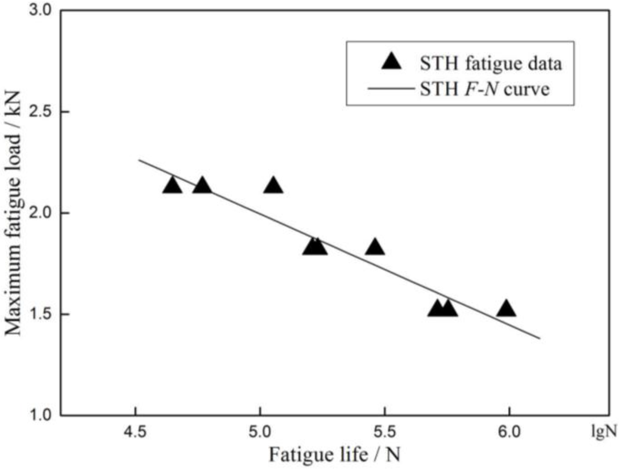
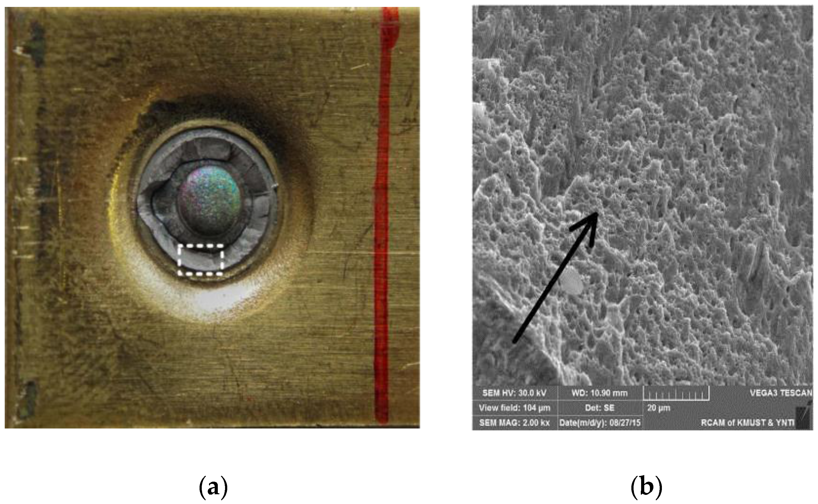
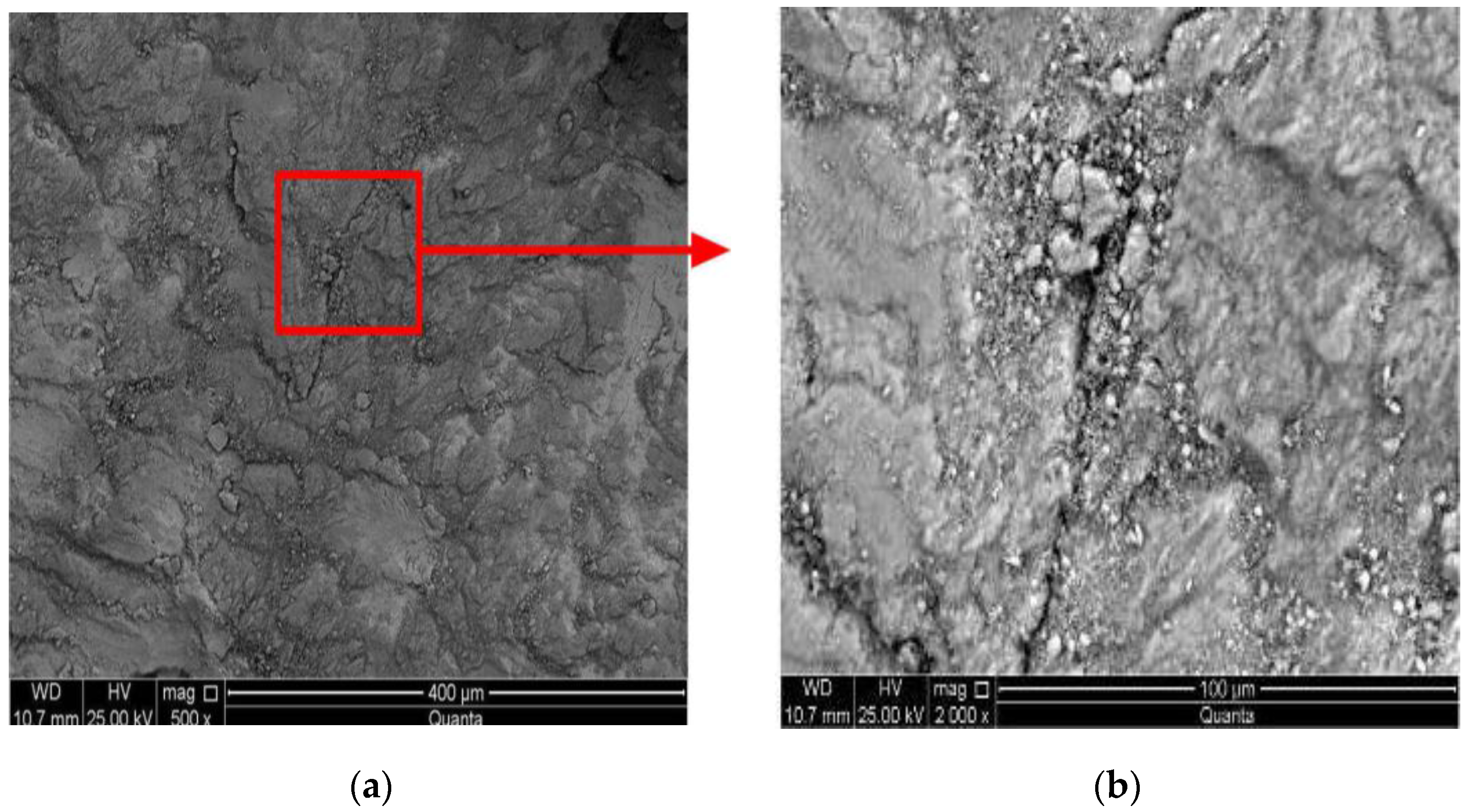
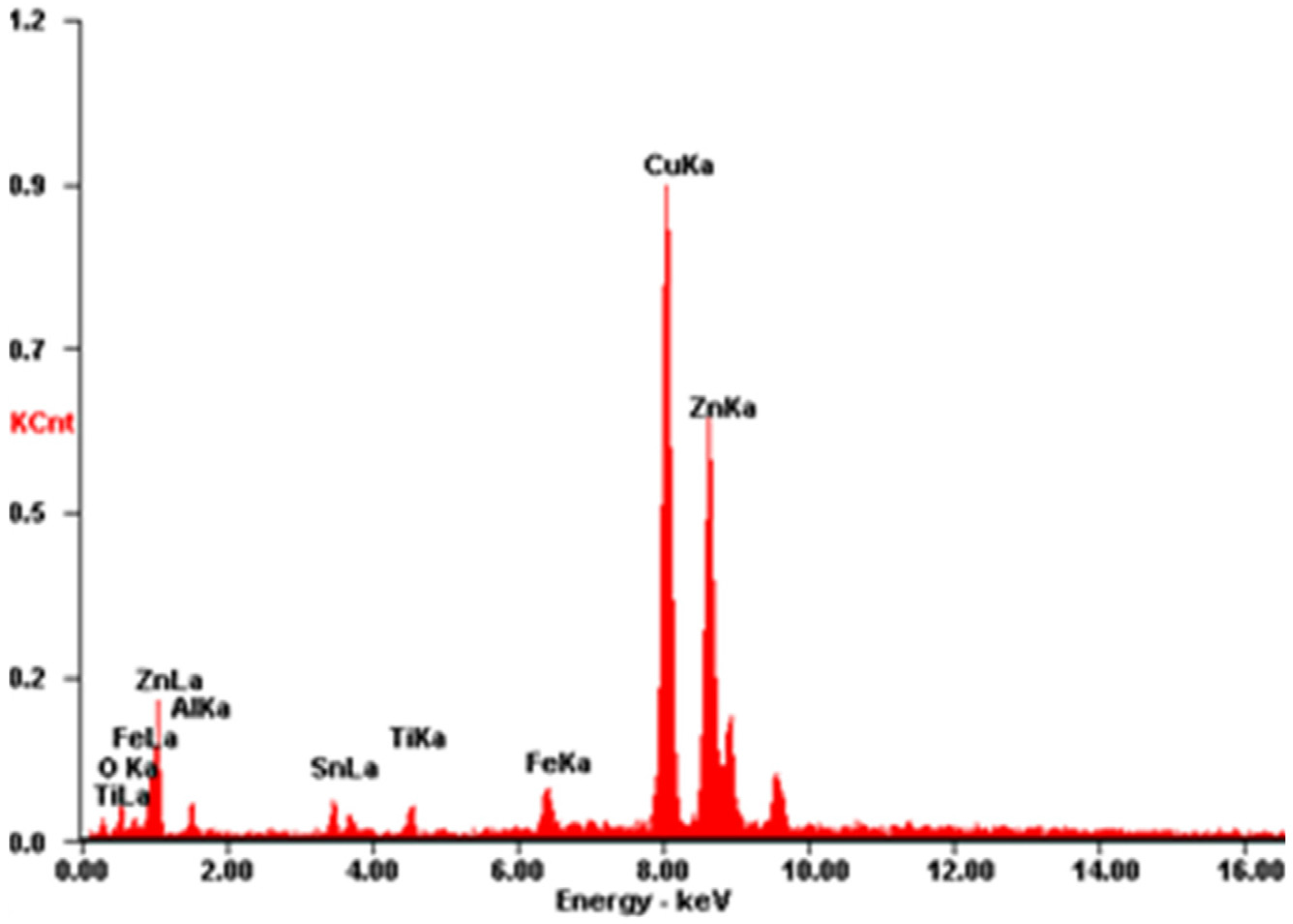
The present paper deals with the fretting performance of SPR joints in dissimilar sheets of titanium (TA1) and copper (H62) alloys (defined as STH joints). Fatigue load–fatigue life curves were obtained via tension-tension fatigue tests to characterize the fatigue properties of the joints. The typical fracture interfaces were analyzed by scanning electron microscopy (SEM) and energy-dispersive X-ray spectroscopy (EDX) techniques. The results showed that there was extremely severe fretting at the contact interfaces of rivet and sheet materials for the joints at relatively high load levels. In addition, the severe fretting in the region of the locked sheet in contact with the rivet was the major cause of broken locked sheets for the joints at low load level.

2. Experimental Procedure

2.1. Materials

The materials used in this study were TA1 titanium alloy (TA1) sheets (Baoji Chuangxin Metal Materials Co. Ltd., Baoji, China) and H62 copper alloy (H62) sheets (Baoji Chuangxin Metal Materials Co. Ltd., Baoji, China) with the dimensions 110 mm length × 20 mm width × 1.5 mm thickness. To obtain the sheet mechanical properties, material tests were conducted using an MTS 634.31F-24 extensometer (MTS System Corporation, Eden Prairie, MN, USA) with a 20 mm gauge length on an MTS servo hydraulic test machine (MTS System Corporation, Eden Prairie, MN, USA). The chemical compositions of TA1 and H62 sheets are shown in Table 1, and the stress–strain curves at a constant crosshead speed of 5 mm/min are exhibited in Figure 1.

2.2. Specimens Preparation

As mentioned previously, SPR is a new high-speed mechanical fastening technique for point joining of sheet materials. To date, no agreed standard for testing SPR joints exists. The most common test configuration performed in previous studies was the single overlap joint, since it is simple and quick to fabricate. All specimen designs and joint tests referred to China welding standard (GB-2649). As shown in Figure 2, the specimens used for experimental investigation were of the lap-shear type. All specimens were produced with a rivet and a flat bottom die on a RIVSET VARIO-FC servo-driven riveting machine by Böllhoff (Böllhoff Produktion GmbH & Co. KG, Bielefeld and Sonnewalde, Germany). Both the rivet and the die were fabricated from high-strength steel, and were supplied by Böllhoff Produktion GmbH & Co. The mechanical properties of the rivets used in present paper were as follows: Young’s modulus 206 GPa, Poisson’s ratio 0.3, yield strength 1720 MPa, compressive strength 1595.6 MPa, and Rockwell hardness 44 HRC. The dimensions of the rivet and the die are shown in Figure 3.
To increase the material formability, TA1 sheets in STH joints were heated to 700 °C by an oxyacetylene flame gun. The temperature was controlled by an infrared thermometer (Shenzhen Jumaoyuan Science And Technology Co., Ltd., Shenzhen, China). The SPR processes were produced immediately after heat treatment. The quality of specimens was monitored by an online window monitoring system (Böllhoff Produktion GmbH & Co. KG, Bielefeld and Sonnewalde, Germany) in the riveting equipment during the SPR process. The monitoring was carried out by measuring the actual SPR setting force through a force sensor and the punch travel through a position sensor, and generating a force-travel curve for one SPR joint [17]. The force-travel curves should be almost identical under the same working conditions for different joints. This indicates that the quality of corresponding joints is good. Through the online window monitoring system, all specimens used were judged as qualified. The satisfied joining parameters of STH joints in terms of punch travel, pre-clam pressure, riveting pressure, and compressing pressure were 131.20 mm, 50 bar, 195 bar, and 110 bar, respectively. Twenty-five STH joints were made, ten of which were selected randomly for the static tests. The rest were prepared for the fatigue tests.

3. Static Tests and Results Analysis

The static tests were conducted on an MTS servo hydraulic testing machine using tensile-shear mode. Spacers with dimensions of 25 mm length × 20 mm width × 1.5 mm thickness were glued on both ends of the specimens to reduce the influence of additional bending and to centralize the load. Ten tests for the STH joints were conducted in turn. The tests were performed with a constant displacement rate of 5 mm/min and terminated when the sheets were separated or the force dropped to 5% of the peak force value. Continuous records of the applied force-displacement curves were obtained during each test. The tensile process of the STH joints is exhibited in Figure 4.
Figure 5 shows the force-displacement curves and histogram of maximum shear strength of the STH joints. It can be seen from Figure 4 that in static tests of the STH joints, rivets were broken for seven samples, corresponding to the seven relatively low maximum load force-displacement curves in Figure 5. Three joints were not separated completely, which correspond to the force-displacement curve characterized by both high maximum load and high failure deflection in Figure 5.
From Figure 5, it can be seen that the data for the failure load and failure displacement of the STH joints were relatively stable, showing that the results were reliable and repeatable. To examine the rationality of the test data, the normal hypothesis tests were performed using MATLAB software (MathWorks Inc., Natick, MA, USA). As shown in Figure 5, the results show that the tensile-shear strength of the STH joints follow normal distributions. All test data fitting the region bounded by the 95% confidence limits.

4. Fatigue Tests and Results Analysis

It can be obtained from Figure 5a that the average peak load of the STH joints was 6.076 kN. The fatigue test parameters were determined based on the average peak load. The load-controlled cyclic fatigue tests were carried out on the MTS servo hydraulic testing machine using a sine waveform and in tension-tension mode. The load ratio R = 0.1 and the frequency f = 10 Hz were employed for all specimens. Each test was run until 2 million cycles were attained or visible failure occurred. Three load levels of 35% (around 2.1 kN), 30% (around 1.8 kN), and 25% (around 1.5 kN) were performed for the STH joints. Three specimens tested at each load level were randomly selected from the fifteen joints prepared well. To reduce the bending of the sheets and ensure straight-line load paths, spacers were glued to both ends of all specimens in the clamping area. Figure 6 shows the fatigue process of the STH joints.
The fatigue data and the fatigue load-fatigue life (F-N) curve fitted by the least square method are presented in Figure 7. The calculated linear equation of the STH joints is F = 4.739 − 0.549 lgN. It can be seen from Figure 7 that the STH joints had an average cycle number of 72,102 (lgN = 4.9) at the fatigue load of approximately 2.1 kN.
During the static tensile-shear tests, the most STH joints failed with the rivets broken as shown in Figure 4. However, as presented in Figure 6, the failures during the fatigue tests were quite different. At the load level of 35%, all three specimens fractured in the rivet. At the load level of 25%, the locked sheets were broken for all specimens. At the load level of 30%, however, specimens fractured in both failure models.

5. Fretting Failure Mechanism

To analyze the fretting failure mechanisms of the STH joints, SEM (A.S. Tescan Inc., Brno, Czech Republic) and EDX (EDAX Inc., San Diego, CA, USA) techniques were employed to examine the typical fatigue fracture surfaces. As stated previously, the STH joints had an average cycle number of 72,102 at the fatigue load of approximately 2.1 kN. Thus, the macroscopic fatigue fracture surfaces of the STH specimens that failed in the rivet at 2.1 kN were chosen to discuss in detail.
The SEM image of the rivet fracture surface is exhibited in Figure 8, from which the fatigue striations can be obviously observed. This characteristic belongs to the ductile fatigue fracture. It can be seen from the direction marked by an arrow in Figure 8 that fatigue cracks propagated from the outside of the rivet to the inside.
As shown in Figure 9a, the fretting debris could be found in the region near the broken rivet. The corresponding local images of fretting debris are shown in Figure 9b. Based on these features of wear debris, it is inferred that there was extremely severe fretting in the STH joints at load levels of 35% and 30%. Moreover, the severe fretting in the region on the locked sheet in contact with the rivet was the major cause of the broken locked sheet for the STH joints at low load level of 25%.
Figure 10 shows the spectrum of fretting debris near the broken rivet on the locked sheet for STH joints by EDX (EDAX Inc., San Diego, CA, USA) tests. The main ingredient of the fretting debris was deemed to be CuO, and some zinc, stannum, ferrum, and titanium and other elements in smaller quantities were tested. It could be deduced that the metallic oxide at the contact interface was caused by the continuous cyclic load and micro-movement between the rivet and the sheet. In short, the corresponding elements were fallen off from the sheet or the rivet by the fretting wear processes and oxidized to the relevant oxide: TiO2 and CuO.

6. Summary

In this paper, the fretting performance of SPR joining dissimilar sheets in TA1 titanium alloy and H62 copper alloy was studied. The static tests were conducted using tensile-shear mode, and the histograms of maximum shear strength of the STH joints were obtained. Fatigue load–fatigue life curves were obtained via tension-tension fatigue tests to characterize the fatigue properties of the joints. To study the fretting behavior of the STH joints, the typical fracture interfaces were analyzed by SEM and EDX techniques. The results showed that there was extremely severe fretting at the contact interfaces of rivet and sheet materials for the joints at relatively high load levels. Moreover, the severe fretting in the region of the locked sheet in contact with the rivet was the major cause of the broken locked sheets for the joints at low load level. It could be deduced that the metallic oxide at the contact interface was caused by the continuous cyclic load and micro-movement between the rivet and the sheet.

Acknowledgments

This study is supported by the National Natural Science Foundation of China (Grant No. 51565023) and Major Program Foundation of the Education Department of Yunnan Province, China (Grant No. ZD201504).

Author Contributions

Xiaocong He conceived and designed the experiments; Cong Deng and Xianlian Zhang performed the experiments and analyzed the data; Xianlian Zhang contributed reagents/materials/analysis tools; Xiaocong He wrote the paper.

Conflicts of Interest

The authors declare no conflict of interest. The founding sponsors had no role in the design of the study; in the collection, analyses, or interpretation of data; in the writing of the manuscript, and in the decision to publish the results.

References

  1. He, X.; Gu, F.; Ball, A. A review of numerical analysis of friction stir welding. Prog. Mater. Sci. 2014, 65, 1–66. [Google Scholar] [CrossRef]
  2. He, X. Finite Element Analysis of Laser Welding: A State of Art Review. Mater. Manuf. Process. 2012, 27, 1354–1365. [Google Scholar] [CrossRef]
  3. Mucha, J. The failure mechanics analysis of the solid self-piercing riveting joints. Eng. Fail. Anal. 2015, 47, 77–88. [Google Scholar] [CrossRef]
  4. Kang, S.; Kim, H. Fatigue strength evaluation of self-piercing riveted Al-5052 joints under different specimen configurations. Int. J. Fatigue 2015, 80, 58–68. [Google Scholar] [CrossRef]
  5. Su, Z.; Lin, P.; Lai, W.; Pan, J. Fatigue analyses of self-piercing rivets and clinch joints in lap-shear specimens of aluminum sheets. Int. J. Fatigue 2015, 72, 53–65. [Google Scholar] [CrossRef]
  6. Calabrese, L.; Proverbio, E.; Pollicino, E.; Galtieri, G.; Borsellino, C. Effect of galvanic corrosion on durability of aluminium/steel self-piercing rivet joints. Corros. Eng. Sci. Technol. 2015, 50, 10–17. [Google Scholar] [CrossRef]
  7. Lou, M.; Li, Y.; Wang, Y.; Wang, B.; Lai, X. Influence of resistance heating on self-piercing riveted dissimilar joints of AA6061-T6 and galvanized DP590. J. Mater. Process. Technol. 2014, 214, 2119–2126. [Google Scholar] [CrossRef]
  8. Haque, R.; Williams, N.; Blacket, S.; Durandet, Y. A simple but effective model for characterizing SPR joints in steel sheet. J. Mater. Process. Technol. 2015, 223, 225–231. [Google Scholar] [CrossRef]
  9. Li, Y.B.; Wei, Z.Y.; Wang, Z.Z.; Li, Y.T. Friction self-piercing riveting of aluminum alloy AA6061-T6 to magnesium alloy AZ31B. J. Manuf. Sci. Eng. Trans. ASME 2013, 135, 6. [Google Scholar] [CrossRef]
  10. Liu, X.; Lim, Y.C.; Li, Y.B.; Tang, W.; Ma, Y.W.; Feng, Z.L.; Ni, J. Effects of process parameters on friction self-piercing riveting of dissimilar materials. J. Mater. Process. Technol. 2016, 237, 19–30. [Google Scholar] [CrossRef]
  11. Ma, Y.W.; Li, Y.B.; Hu, W.; Lou, M.; Lin, Z.Q. Modeling of Friction Self-Piercing Riveting of Aluminum to Magnesium. J. Manuf. Sci. Eng. Trans. ASME 2016, 138, 6. [Google Scholar] [CrossRef]
  12. Haque, R.; Durandet, Y. Strength prediction of self-pierce riveted joint in cross-tension and lap-shear. Mater. Des. 2016, 108, 666–678. [Google Scholar] [CrossRef]
  13. Kang, J.; Rao, H.; Zhang, R.; Avery, K.; Su, X. Tensile and fatigue behaviour of self-piercing rivets of CFRP to aluminium for automotive application. IOP Conf. Ser. Mater. Sci. Eng. 2016, 137, 1. [Google Scholar] [CrossRef]
  14. Mucha, J.; Witkowski, W. Mechanical Behavior and Failure of Riveting Joints in Tensile and Shear Tests. Strength Mater. 2015, 47, 755–769. [Google Scholar] [CrossRef]
  15. Chung, C.-S.; Kim, H.-K. Fatigue strength of self-piercing riveted joints in lap-shear specimens of aluminium and steel sheets. Fatigue Fract. Eng. Mater. Struct. 2016, 39, 1105–1114. [Google Scholar] [CrossRef]
  16. He, X.; Wang, Y.; Lu, Y.; Zeng, K.; Gu, F.; Ball, A. Self-piercing riveting of similar and dissimilar titanium sheet materials. Int. J. Adv. Manuf. Technol. 2015, 80, 2105–2115. [Google Scholar] [CrossRef]
  17. Zhao, L.; He, X.; Xing, B.; Lu, Y.; Gu, F.; Ball, A. Influence of sheet thickness on fatigue behavior and fretting of self-piercing riveted joints in aluminum alloy 5052. Mater. Des. 2015, 87, 1010–1017. [Google Scholar] [CrossRef]
Figure 1. Stress–strain curves for TA1 and H62 sheet materials.
Metals 06 00312 g001
Figure 2. Specimen geometry (dimensions in mm).
Metals 06 00312 g002
Figure 3. Dimensions of the rivet and the die (dimensions in mm): (a) Rivet; (b) Die.
Metals 06 00312 g003
Figure 4. Tensile process of the STH joints.
Metals 06 00312 g004
Figure 5. Force-displacement curves and histogram of maximum shear strength of the STH joints. (a) Force-displacement curves; (b) Histogram of maximum shear strength.
Metals 06 00312 g005
Figure 6. Fatigue process of the STH joints.
Metals 06 00312 g006
Figure 7. F-N curve of the STH joints.
Metals 06 00312 g007
Figure 8. SEM (scanning electron microscopy) images of fracture surface for the STH specimens (load level of 35%). (a) Fracture surface of the rivet; (b) Enlarged fracture area.
Metals 06 00312 g008
Figure 9. An example of SEM analysis of oxide debris in the STH specimens (load level of 35%). (a) Fretting debris; (b) Enlarged fretting debris.
Metals 06 00312 g009
Figure 10. An example of energy-dispersive X-ray spectroscopy (EDX) analysis of oxide debris in the STH specimens.
Metals 06 00312 g010
Table 1. Chemical compositions of TA1 and H62 sheet materials.
MaterialFeCNHOTi
TA10.020.010.010.0010.08Rest
MaterialZnFePbPCu-
H6236.80.150.080.01Rest-

