Article

The Structural Evolution and Segregation in a Dual Alloy Ingot Processed by Electroslag Remelting

1
The State Key Laboratory of Refractories and Metallurgy, Wuhan University of Science and Technology, Wuhan 430081, China
2
Key Laboratory for Ferrous Metallurgy and Resources Utilization of Ministry of Education, Wuhan University of Science and Technology, Wuhan 430081, China
3
Collaborative Innovation Center of Steel Technology, University of Science and Technology Beijing, Beijing 100083, China
4
School of Metallurgy, Northeastern University, Shenyang 110004, China
*
Author to whom correspondence should be addressed.
Metals 2016, 6(12), 325; https://doi.org/10.3390/met6120325
Submission received: 28 November 2016 / Revised: 15 December 2016 / Accepted: 16 December 2016 / Published: 21 December 2016
(This article belongs to the Special Issue Alloy Steels)

Abstract

:
The structural evolution and segregation in a dual alloy made by electroslag remelting (ESR) was investigated by various analytical techniques. The results show that the macrostructure of the ingot consists of two crystallization structures: one is a quite narrow, fine, equiaxed grain region at the edge and the other is a columnar grain region, which plays a leading role. The typical columnar structure shows no discontinuity between the CrMoV, NiCrMoV, and transition zones. The average secondary arm-spacing is coarsened from 35.3 to 49.2 μm and 61.5 μm from the bottom to the top of the ingot. The distinctive features of the structure are attributed to the different cooling conditions during the ESR process. The Ni, Cr, and C contents markedly increase in the transition zone (TZ) and show a slight increase from the bottom to the top and from the surface to the center of the ESR ingot due to the partition ratios, gravity segregation, the thermal buoyancy flow, the solutal buoyancy flow, and the inward Lorentz force. Less dendrite segregation exists in the CrMoV zone and the transition zone due to a stronger cooling rate (11.1 and 4.5 °C/s) and lower Cr and C contents. The precipitation of carbides was observed in the ingot due to a lower solid solubility of the carbon element in the α phase.

Graphical Abstract

1. Introduction

With the increase in power generation efficiency of single-cylinder steam turbines using a combined cycle, the rotor produced by the traditional bolted high/intermediate pressure-low pressure shaft has unmet needs. Compared with the traditional bolted shaft, the dual alloy shaft can provide a significant improvement in power generating efficiency. The manufacture of a dual alloy shaft via welding technology requires a long production cycle. Electroslag remelting (ESR) has the advantage of producing dual alloy ingots, which can improve the dual alloy single shaft yield and quality. During the production process, two pre-melted steel rods containing different alloy compositions are connected via welding to form a single electrode, and the single electrode is then remelted with ESR technology [1].
In the ESR process, a Joule heating created by the alternating current travelling through the highly resistive molten slag is sufficient to melt the electrode. Then, metal droplets are formed at the electrode tip. Due to the higher density, the metal droplets pass through the liquid slag layer and form a liquid metal pool in the water-cooled mold, which can purify liquid metal. With the heat transferring to the mold, the liquid metal is solidified to forming an ingot. Furthermore, a Lorentz force is created by the interaction between the self-induced magnetic field and the current [2]. The final quality and properties of the ingot strongly depend on the microstructure forming during the solidification process.
In order to obtain a high quality ESR dual alloy ingot, it is necessary to achieve a narrow chemical transition zone (TZ) of the ingot and maintain a continuous structure in TZ because a distorted chemical transition zone and discontinuous structure might increase the risk of running the rotor at high temperature due to thermal expansion mismatch [3]. The structure of an ESR ingot mainly consists of columnar grains and equiaxed grains. The grain growth direction and the secondary dendrite arm spacing (SDAS) are the most important macro- and microstructure factors for ingot quality. The grain growth direction is generally defined by the grain growth angle, which is the angle between the primary dendrites of the grain and the axis of the ingot [4]. Practice has shown that ESR ingots with a small grain growth angle can exhibit improved hot forging performance [5]. Enormous mathematical models and experiments [4,5,6,7] have confirmed that the local temperature gradients and solidification conditions have a vital effect on the structure of ESR ingots. However, the subtle differences of the structural evolution in different zones of ESR dual alloy ingot have rarely been reported. Macrosegregation is one of most common and serious defects in ESR ingots that occurs in the solidification process because of the uneven distribution of the solute in the liquid and solid phases [2]. Dendrite segregation is also common in ESR ingots due to interdendritic elemental enrichment [7]. Some researchers have used mathematical models to study the element redistribution in ingots [8,9]. The solute transport in the ESR process is dominated by the combined effect of the Lorentz force, the solutal buoyancy, and the thermal buoyancy. However, the experimental research of the segregation in different zones of the ESR dual alloy ingot is also relatively lacking.
Because of these factors, the authors were motivated to experimentally explore the underlying mechanism of the evolution of the structure and segregation of ESR dual alloy ingots in detail. The subtle differences of the structures and segregation in different zones (CrMoV zone, the TZ, and the NiCrMoV zone) of an ESR ingot were determined. This work is designed to provide fundamental research for the structure and segregation of ESR dual alloy ingots, providing basic knowledge for the manufacture of the dual alloy rotor for use in steam turbines.

2. Experimental Section

2.1. Experimental Apparatus and Method

The experiment was carried out using a laboratory-scale electroslag furnace (Herz, Shanghai, China) with a copper mold under an open air atmosphere. The inner diameter, the lateral wall thickness, and the height of the mold were 120, 65, and 600 mm, respectively. The weight of the ESR ingot was about 35.5 kg in the present experiment. The electrode was comprised of two pieces of pre-melted bars, and connected via welding. The upper part was an NiCrMoV alloy bar (Elec. NiCrMoV), and the lower one was an CrMoV alloy bar (Elec. CrMoV). The chemical composition of the consumable electrode is displayed in Table 1, which was examined by the ICP-AES (Tailun, Shanghai, China), the carbon and sulfur analyzer (Jinbo, Wuxi, China), and the oxygen and nitrogen analyzer (LECO, St. Joseph, MO, USA). The slag was composed of 70 mass pct calcium fluoride and 30 mass pct aluminum oxide. The weight and the thickness of the slag layer were 2.3 kg and about 60 mm, respectively. The root-mean-square value and frequency of the alternating current were constant at 1500 A and 50 Hz.

2.2. Specimen Preparation and Analyzing Methods

The dual alloy ingot was equally split into two parts along the length using wire-electrode cutting. Steel filings were obtained by drilling along the longitudinal centerline of the section every 20 mm, and along the transverse radius every 15 mm for C, Cr, and Ni analysis, as shown in Figure 1. The Ni, Cr, and C contents in the ingot were analyzed with the ICP-AES and the carbon and sulfur analyzer. Three slices were taken from the upper (NiCrMoV), middle (TZ), and lower parts (CrMoV) of the ingot, and three 6 × 6 × 6 mm3 specimens A (NiCrMoV), B (TZ), and C (CrMoV) were then sampled from three slices, respectively (Figure 1). The NiCrMoV zone, the TZ (transition zone), and the CrMoV zone were decided according to the composition profile along the ESR ingot axial. Another part of the ingot was ground, polished, and finally etched via aqua regia for a certain time. Figure 2 illustrates the macrostructure of the dual alloy ingot. The three specimens were etched at 75 °C in a picric acid solution for metallographic observation by optical microscopy (OM, Carl Zeiss, Jena, Germany), then ground, polished, and etched via aqua regia for determining dendrite segregation via scanning electron microscopy (SEM, FEI, Hillsboro, OR, USA) coupled with energy dispersive spectrometer (EDS, Oxford Instruments, Oxford, UK). A carbon replica specimen was examined in a transmission electron microscopy (TEM, JEOL, Tokyo, Japan) operating at 200 kV for selected-area electron diffraction (SAED) analysis to observe the precipitates.

3. Results and Discussions

3.1. Macro- and Microstructure Evolution of Steel Ingot Made via the Electroslag Remelting (ESR) Process

Two structures of the crystal are shown in Figure 2b—one is a quite narrow, fine, equiaxed grain region at the edge, and the other is a columnar grain region, which plays a leading role. The typical columnar structure shows no discontinuity between the CrMoV zone, the NiCrMoV zone, and the transition zone (Figure 2b,c). A thin layer of the equiaxed grain is located under the ingot surface, and the columnar grain grows inside the ingot. The columnar grain nucleates at the bottom and grows upward (inside the frame in Figure 2b). Meanwhile, the columnar grain nucleated at the lateral wall grows in a certain angle. After a period of growth, the two columnar grains would meet each other, and the inclined columnar grain hinders the growth of the vertical columnar grain. The inclined columnar grain continuously grows to the center of the ingot, which forms an inverted chevron structure with an angle ranging from 30° to 37° (from Angle 1 to Angle 2 in Figure 2b) with respect to the vertical axis. The columnar grain at the top is almost perpendicular to the vertical axis. After longer time etching, the CrMoV zone is darker than the TZ and the NiCrMoV zone due to the lower Cr and Ni contents (Figure 2c). The variation in optical microstructure at different positions (A, B, and C) throughout the cross section of the ESR ingot is shown in Figure 3a–c. The dendritic structure is formed throughout the cross section, which gradually becomes coarsened from the bottom (Figure 3c) to the top (Figure 3a) of the ingot. The secondary dendrite arm-spacing (SDAS) measured at the bottom, middle and top of the ingot is shown in Figure 3d. The average SDAS is the average of four SDAS’s at three sampling points. The average SDAS throughout the section at the bottom, middle, and top parts of the ingot are 35.3, 49.2, and 61.5 μm, respectively. The cooling rate (CR/ °C/s) can be calculated by Equation (1) as follows [10]:
λ S ( μ m ) = ( 169.1 720.9 [ % C ] ) C R 0.4935 ( 0   <   [ % C ] 0.15 )
According to Equation (1), the cooling rates of the bottom, middle and top parts of the ingot are 11.1, 4.5, and 2.3 °C/s, respectively. This indicates that the cooling intensity decreases from the bottom to the top of the ingot.

3.2. Macrosegregation of the ESR Ingot

The distributions of Ni, Cr, and C concentrations along the vertical centerline and radius in the ESR ingot are shown in Figure 4. Figure 4a indicates that the Ni, Cr, and C contents markedly increase in the transition zone until they reaches the nominal concentration of Elec. NiCrMoV. It can be seen from Figure 4b that the Ni, Cr, and C contents at the middle of the ingot are higher than those at the surface.
In our previous work, we studied the fluid flow during the ESR process [1,9,11]. The metal droplets formed at the electrode tip sink through the slag layer to form a crescent-shaped molten metal pool in the mold, which is deep in the center of the ingot and becomes shallow gradually outward along the radius. Figure 5 illustrates the flows of the molten slag and metal pools during the ESR process. The flow in the metal pool is induced by the thermal buoyancy and the Lorentz forces [12,13]. The metal near the mold is cooled by the water through the mold, resulting in a lower temperature and higher density. Then, the hot metal will float up and the cold metal will sink down, and a circular flow is formed in the vicinity of the water-cooled mold due to the thermal buoyancy flow. The large temperature difference at the solidification front also gives rise to a clockwise circular flow. The cool metal moves down along the inclined solidification front and washes out the solidifying mushy zone. Around the base of the metal pool, the cooling intensity decreases and the hot metal turns up toward the slag–metal interface and then back to the mold wall. Furthermore, according to Faraday’s law of electromagnetic induction, the downward current would induce a clockwise circular magnetic field (looking down from the top). The interaction between the downward current and the clockwise magnetic field creates an inward Lorentz force, which also pushes the metal from the periphery to the bottom.
The solute elements Ni, Cr, and C become enriched in the mushy zone in Ni, Cr, and C because of their partition ratios (kNi = 0.94, kCr = 0.76, and kC = 0.34) [14] between solid and remained liquid alloy, which are less than 1. In addition, the density of C (ρC = 1800 kg/m3) and Cr (ρCr = 6900 kg/m3) is lower than that of iron (ρFe = 7500 kg/m3) [15], resulting in the so-called gravity segregation, with higher Cr and C contents in the liquid. Due to the clockwise circular flow at the solidification front, the solute-poor (Ni, Cr, and C) metal in the pool displaces the solute-rich metal through washing the mushy region. Furthermore, the solute enrichment increases the metal density and thus promotes the sinking of the liquid metal [16,17]. As a result, the Ni, Cr, and C accumulate at the base of the pool and the concentration increases with increasing distance from the bottom of the ingot. There is a lower concentration region at the outer layers of the ingot, where solidification occurs first and Ni, Cr, and C are depleted. The solute transport during the ESR process is dominated by the Lorentz force, the thermal and solutal buoyancy forces, and the gravity segregation.

3.3. Microsegregation and Precipitates of the ESR Ingot

Figure 6 shows the SEM micrograph of the dendrite segregation in the ESR ingot. It indicates that severe dendrite segregation occurs in interdendritic areas. In order to analyze the solute-rich elemental distribution in interdendritic areas of the ESR ingot, the SEM micrograph and corresponding elemental line scanning image of the interdendritic areas are presented in Figure 7. It reveals that Cr and C elements are enriched in interdendritic areas, whereas the Ni element exhibits a slight decrease (Figure 7b). During the solidification of the ingot, the interdendritic areas enrich carbon and chromium [7], which always form larger carbides (Figure 7a) due to severe dendrite segregation. Furthermore, SEM analysis was conducted to reveal the dendrite segregation distribution in Specimens A (NiCrMoV), B (TZ), and C (CrMoV). The magnified micrographs of the specimens are presented in Figure 8a–c, indicating that dendrite segregation becomes severer from the bottom to the top of the ingot. This is the result of different cooling intensities and Cr and C contents. Less dendrite segregation exists in the CrMoV zone and the TZ due to stronger cooling rates (11.1 and 4.5 °C/s) and lower Cr and C contents.
The SEM micrograph and EDS spectral image of precipitates observed in the ESR ingot are shown in Figure 9. Figure 9a shows that precipitates distribute randomly, and the size of the big precipitates is up to about 40 μm. The corresponding EDS analysis reveals the precipitates mainly consist of C, Cr, Ni, and Fe (Figure 9b). In order to analyze the precipitates in detail, TEM analysis were conducted to reveal the crystal structure of the precipitates. Figure 10 shows the TEM micrograph and the corresponding SAED patterns of the precipitates. According to the analysis of the SAED, the spots (31 1 ¯ ) and ( 2 ¯ 4 2 ¯ ) correspond to M23C6 with an FCC crystal structure in Figure 10b. The M23C6 carbide is common in high chromium steel [18]. In the present work, the ingot contains 0.074%–0.106% carbon, and it belongs to hypoeutectoid steel. During the solidification of the ingot, the γ phase transformed to the α phase and the solid solubility of carbon in the α phase was lower, which resulted in carbon enrichment. Enriched carbon always combines with Cr or another alloying element to form large carbides. Fine M23C6 carbides can improve the strength and toughness of steel by the mechanism of precipitation strengthening [18]: (1) pinning the grain boundary and hindering the movement of grain boundaries; (2) confining the creep cavity between the precipitated phase, making it difficult to grow, prolonging the rupture time; and (3) changing the solid solution of the two sides of the grain boundary, improving the sliding ability of dislocation near the grain boundary, improving the plasticity of the grain boundary, and eliminating notch sensitivity. However, the massive precipitates easily form the crack source and reduce the strength of the matrix. In the present work, the some precipitates are massive, which is detrimental to the strength of the matrix. The dimensions of M23C6 in the ESR ingot were larger than those of the carbides generated by the thermal treatments as reported in the literature [19,20]. This indicates that an appropriate heat treatment process is expected to eliminate the severer dendrite segregation and dissolve the massive carbides. Otherwise, the massive carbides and severer dendrite segregation would stay and distribute in the structure.

4. Conclusions

The following conclusion can be drawn from the present study.
(1)
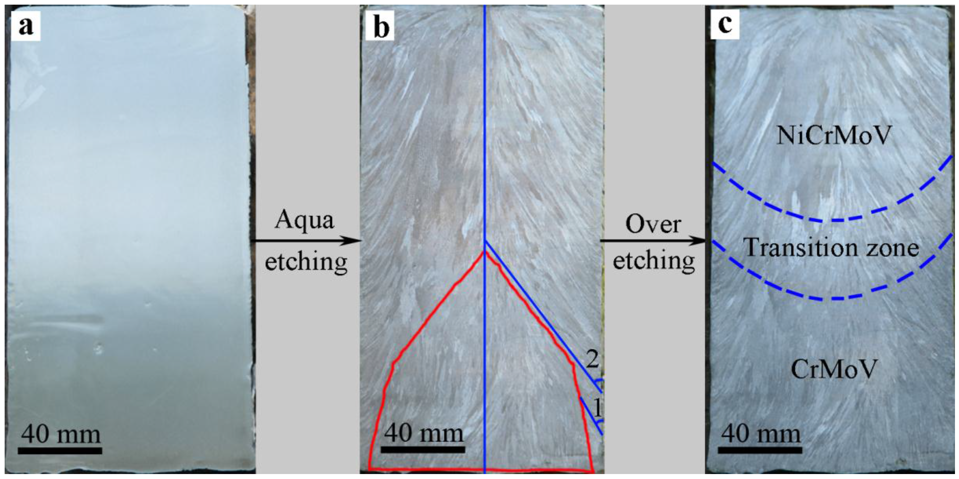
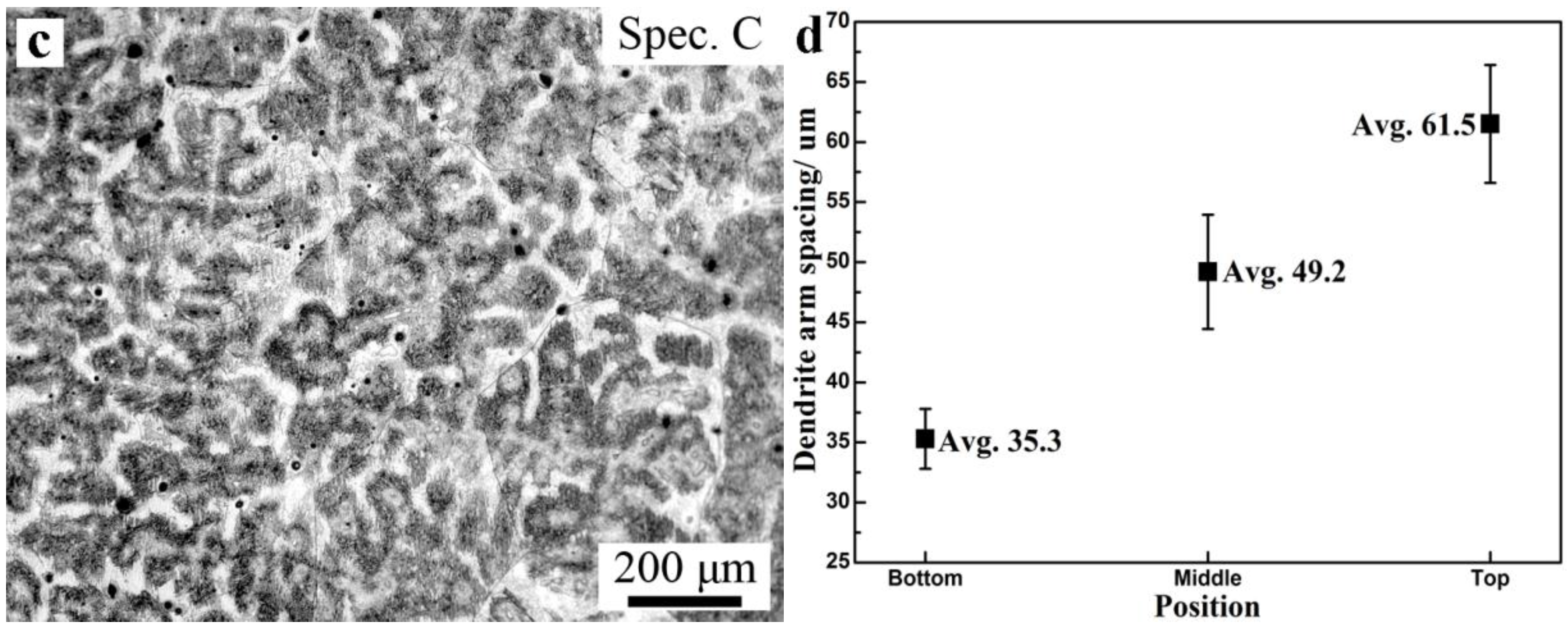
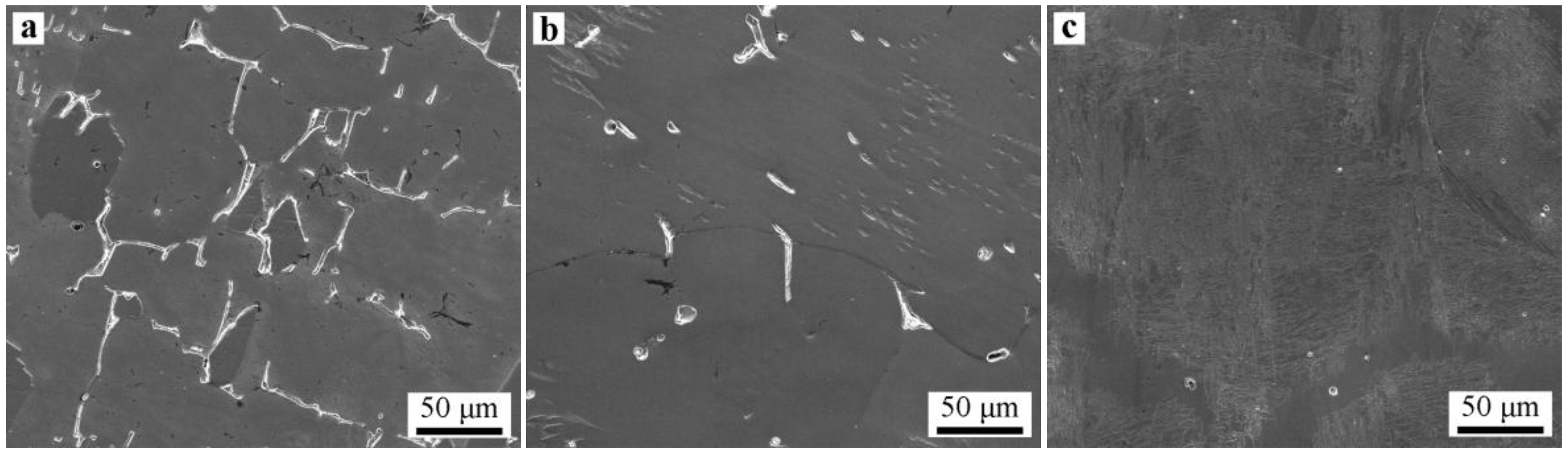
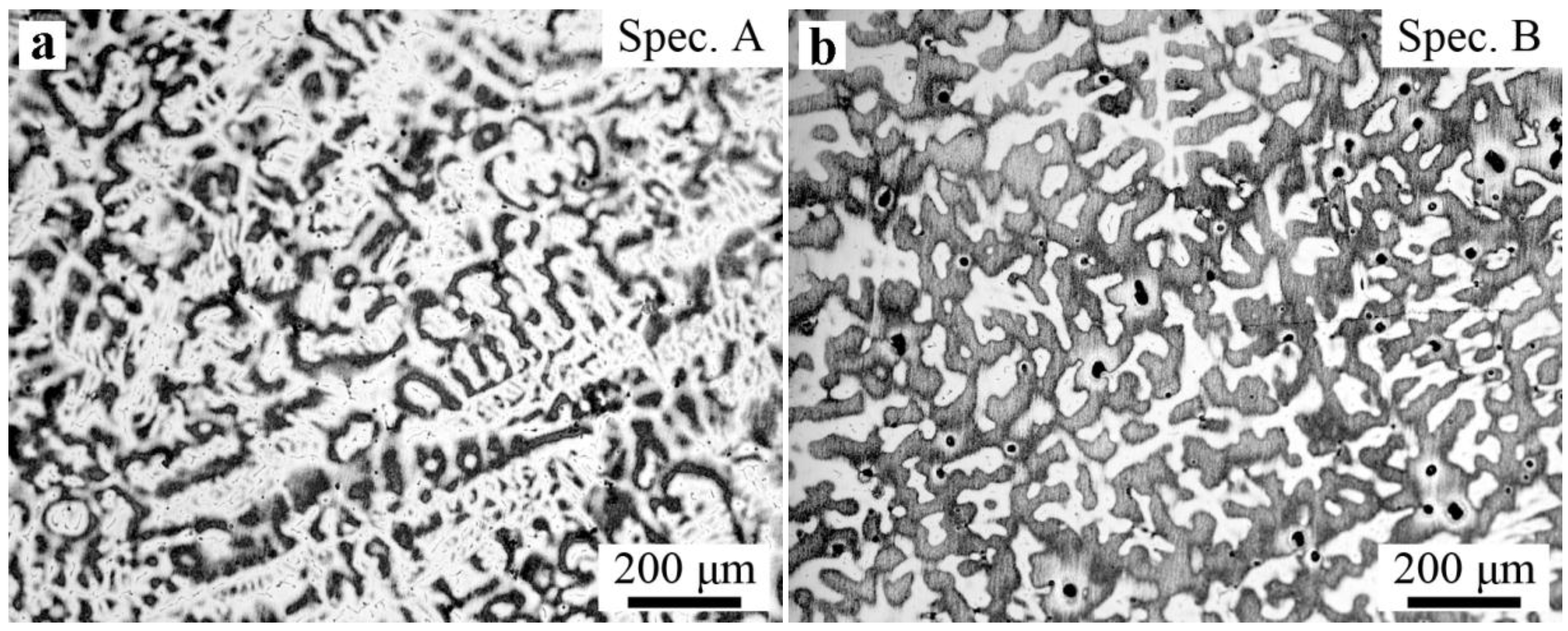
Two crystallization structures were observed in the ESR ingot: one is a quite narrow, fine, equiaxed grain region at the edge of the ingot, and the other is a columnar grain region, which plays a leading role. The typical columnar structure shows no discontinuity between the CrMoV zone, the NiCrMoV zone, and the transition zone. The average second arm-spacing is coarsened from 35.3 to 49.2 μm and 61.5 μm from the bottom to the top of the ingot. The distinctive features of the structure are attributed to different cooling conditions during the ESR process.
(2)
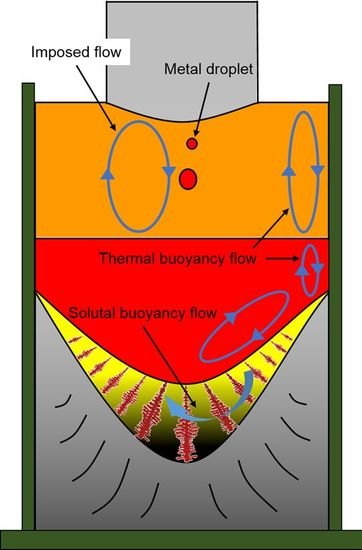
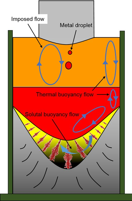
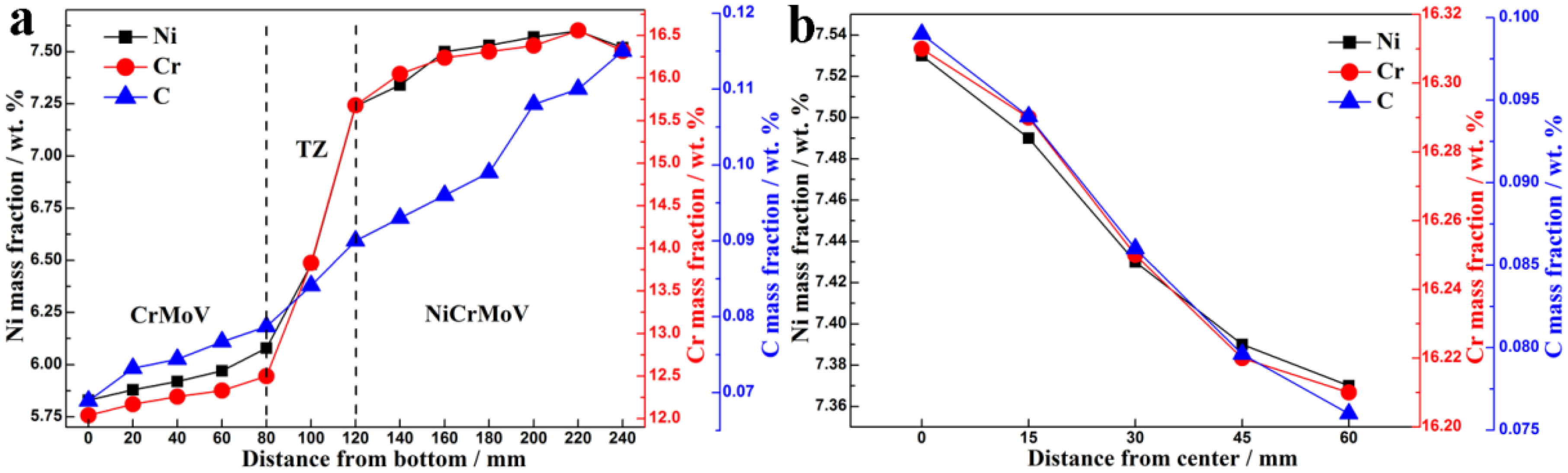
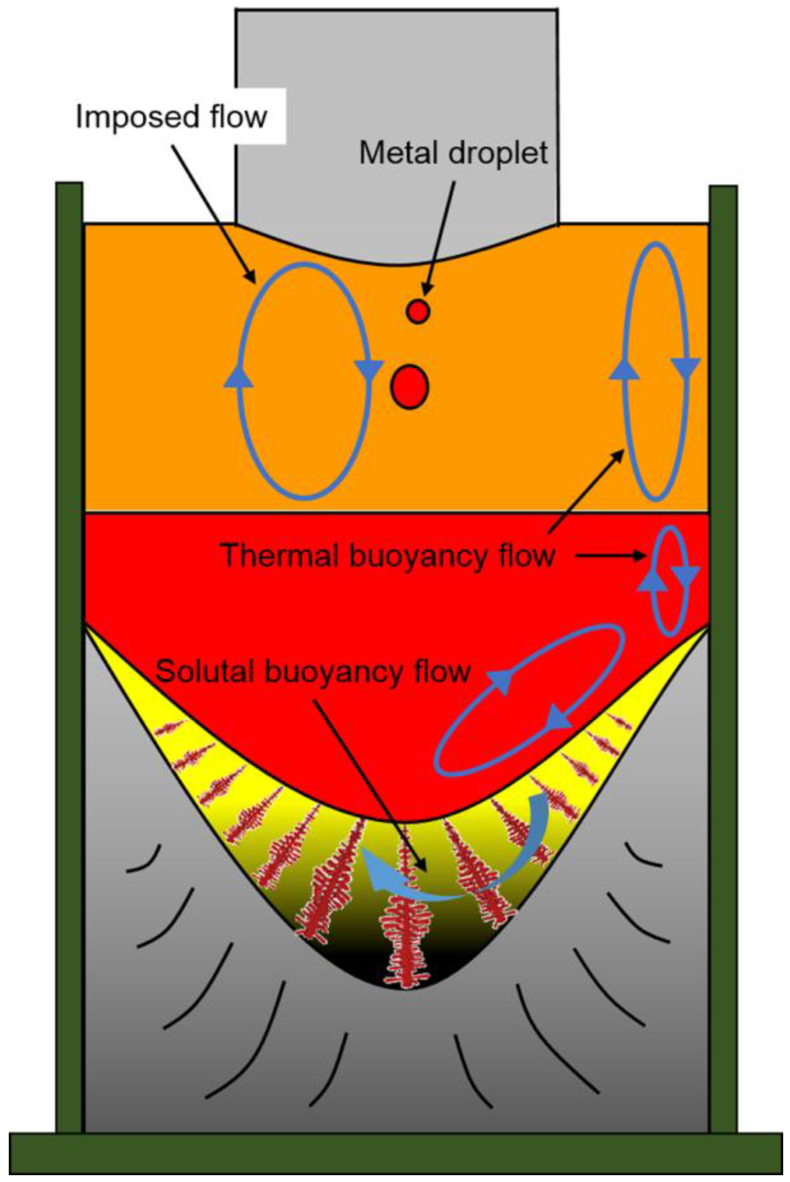
The Ni, Cr, and C show a slight increase from the end to the top and from the surface to the center of the ESR ingot due to the partition ratios, gravity segregation, the thermal buoyancy flow, the solutal buoyancy flow, and the inward Lorentz force. The Ni, Cr, and C contents markedly increase in the transition zone until it reaches the nominal concentration of Elec. NiCrMoV.
(3)
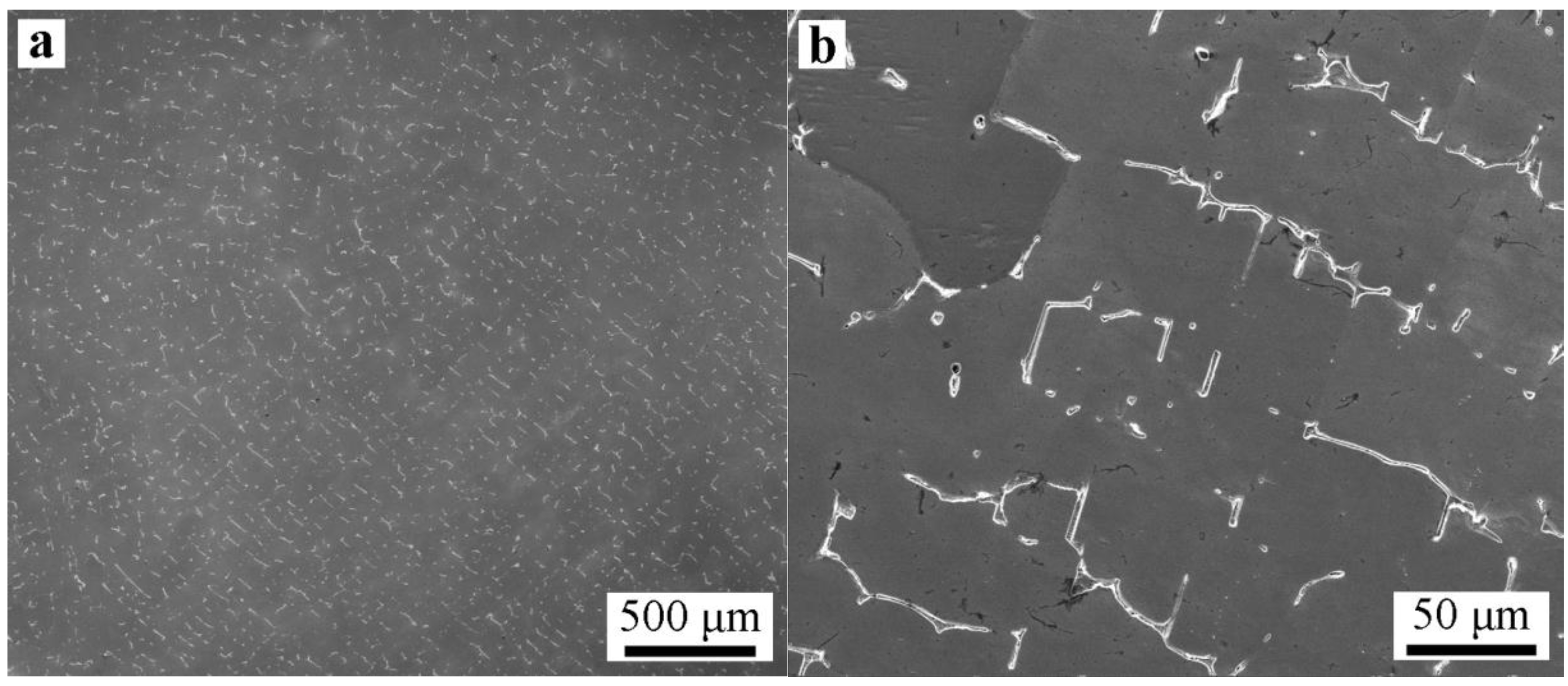
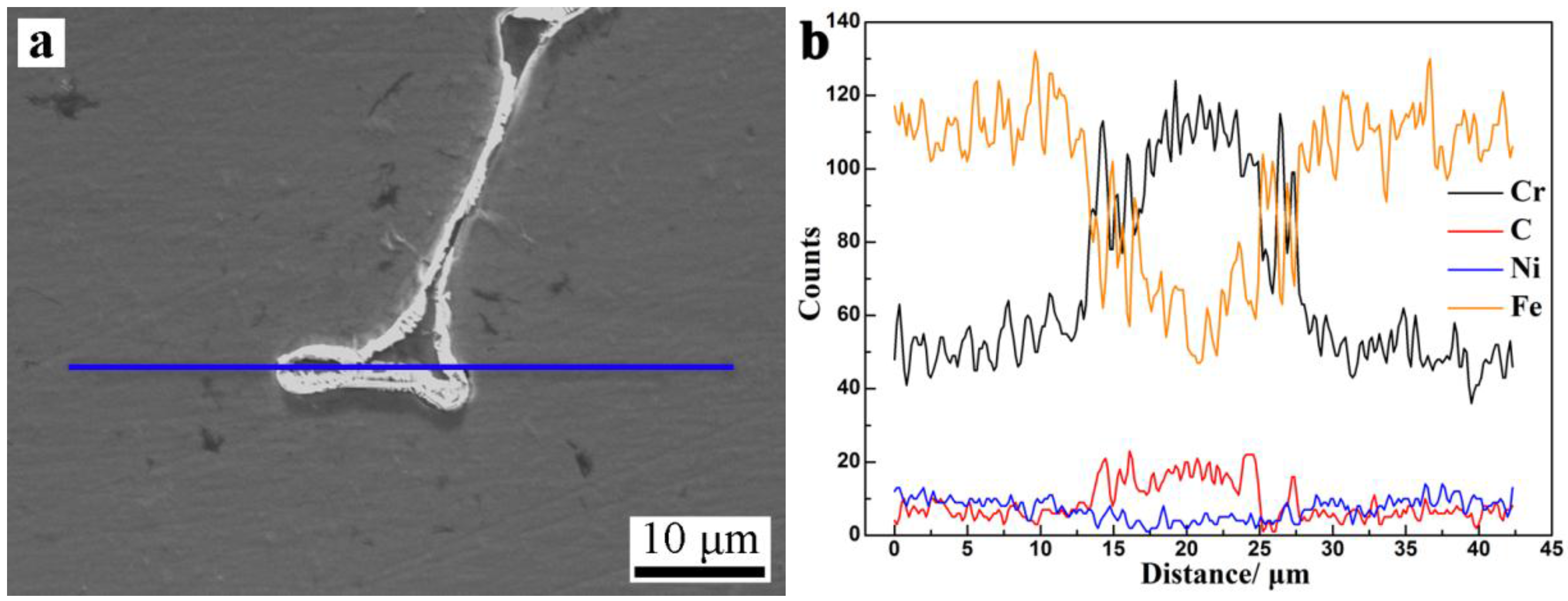
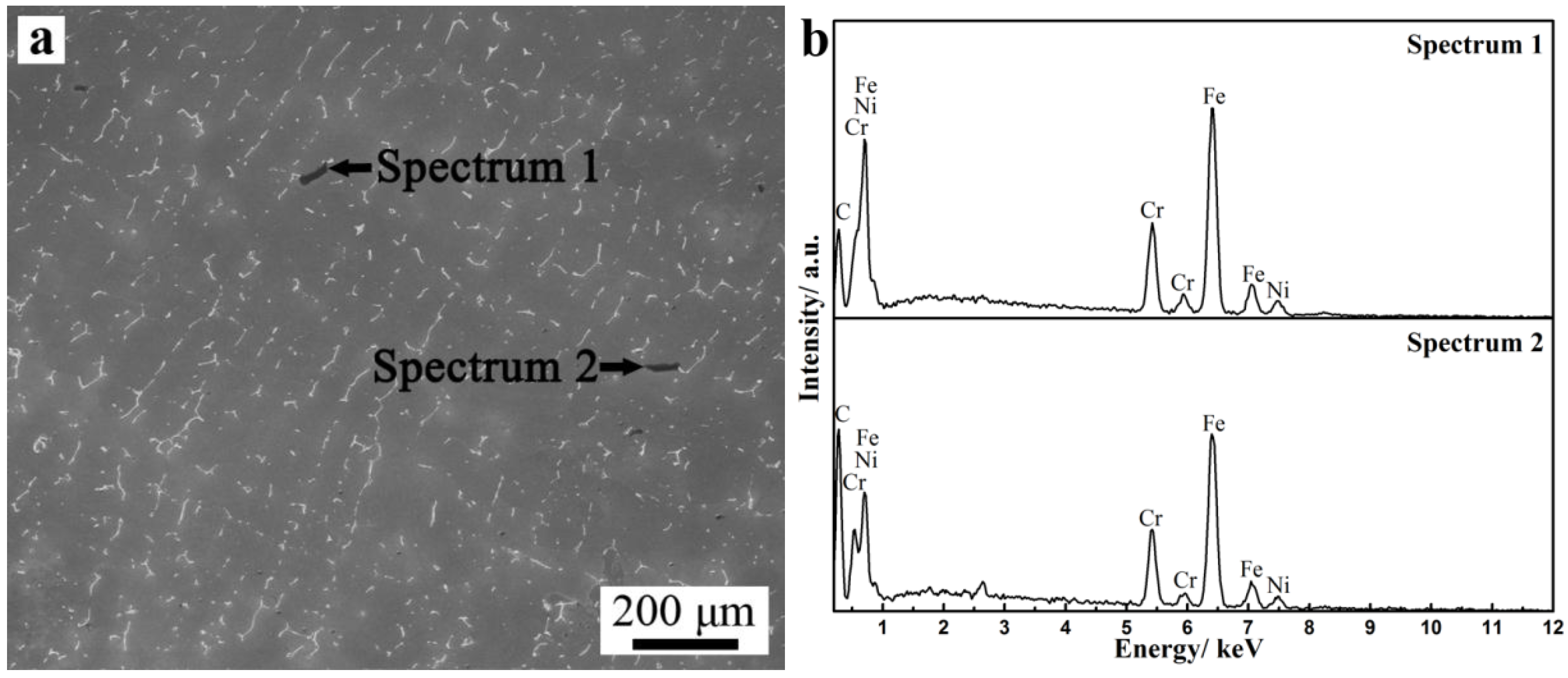
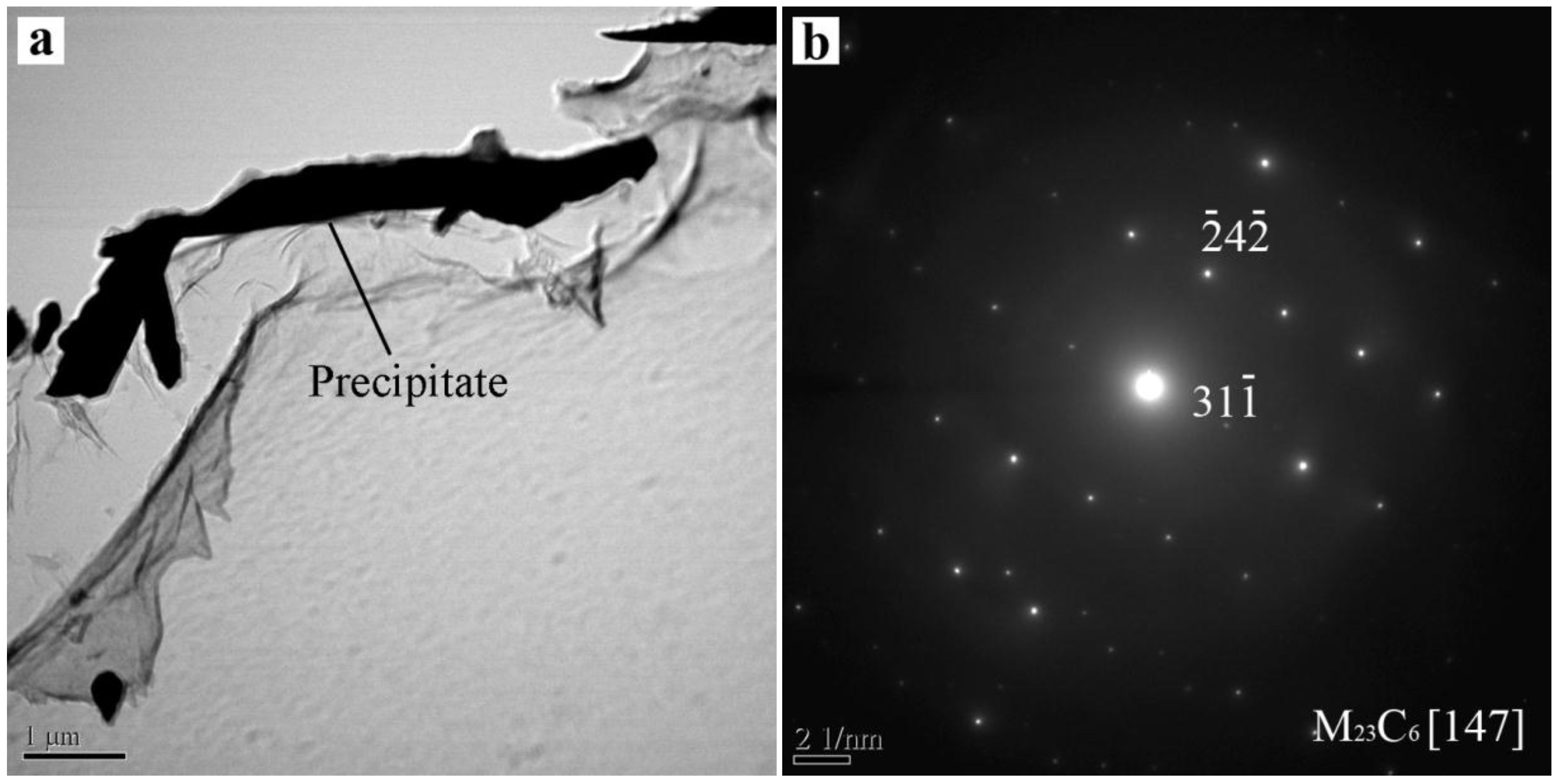
Severe dendrite segregation was observed in the ESR ingot, which becomes severer from the bottom to the top of the ingot. Less dendrite segregation exists in the CrMoV zone and the transition zone due to a stronger cooling rate (11.1 and 4.5 °C/s) and lower Cr and C contents. The precipitation of carbides was observed in the ESR ingot due to a lower solid solubility of the carbon element in the α phase. The massive carbides are detrimental to the strength of the matrix. An appropriate heat treatment process is expected to eliminate the severer dendrite segregation and dissolve the massive carbides. The result of the present work provides a reference for the manufacture of the dual alloy rotor to be used in steam turbines using a combined cycle, which would provide significant improvements in power generating efficiency.

Acknowledgments

The authors gratefully acknowledge the support from the National Natural Science Foundation of China (Grant No. 51210007) and the Key Program of Joint Funds of the National Natural Science Foundation of China and the Government of Liaoning Province (Grant No. U1508214).

Author Contributions

Guangqiang Li and Yu Liu conceived and designed the experiments; Yu Liu, Zhao Zhang and Li Wang performed the experiments; Yu Liu and Qiang Wang analyzed the data; Baokuan Li contributed materials and tools; Yu Liu wrote the paper.

Conflicts of Interest

The authors declare no conflict of interest. The founding sponsors had no role in the design of the study; in the collection, analyses, or interpretation of data; in the writing of the manuscript, and in the decision to publish the results.

Abbreviations

The following abbreviations are used in this manuscript:
ESRelectroslag remelting
TZtransition zone
ICP-AESinductively coupled plasma-atomic emission spectroscopy
OMoptical microscopy
SEMscanning electron microscopy
EDSenergy dispersive spectrometer
TEMtransmission electron microscopy

References

  1. Wang, Q.; Yan, H.; Ren, N.; Li, B. Effect of current on solute transport in electroslag remelting dual alloy ingot. Appl. Therm. Eng. 2016, 101, 546–567. [Google Scholar] [CrossRef]
  2. Wang, Q.; Yan, H.; Ren, N.; Li, B. Effect of slag thickness on macrosegregation and transition zone width of electroslag remelting dual alloy ingot. JOM 2016, 68, 397–400. [Google Scholar] [CrossRef]
  3. Kajikawa, K.; Ganesh, S.; Kimura, K.; Kudo, H.; Nakamura, T.; Tanaka, Y.; Schwant, R.; Gatazka, F.; Yang, L. Forging for advanced trubine applications: Development of multiple alloy rotor forging for turbine application. Ironmak. Steelmak. 2007, 34, 216–220. [Google Scholar] [CrossRef]
  4. Rao, L.; Zhao, J.H.; Zhao, Z.X.; Ding, G.; Geng, M.P. Macro-and microstructure evolution of 5CrNiMo steel ingots during electroslag remelting process. J. Iron Steel Res. Int. 2014, 21, 644–652. [Google Scholar]
  5. Chang, L.Z.; Shi, X.F.; Yang, H.S.; Li, Z.B. Effect of low-frequency AC power supply during electroslag remelting on qualities of alloy steel. J. Iron Steel Res. Int. 2009, 16, 7–11. [Google Scholar] [CrossRef]
  6. Li, B.; Wang, Q.; Wang, F.; Chen, M. A coupled cellular automaton-finite-element mathematical model for the multiscale phenomena of electroslag remelting H13 die steel ingot. JOM 2014, 66, 1153–1165. [Google Scholar] [CrossRef]
  7. Ma, D.; Zhou, J.; Chen, Z.; Zhang, Z.; Chen, Q.; Li, D. Influence of thermal homogenization treatment on structure and impact toughness of H13 ESR steel. J. Iron Steel Res. Int. 2009, 16, 56–60. [Google Scholar] [CrossRef]
  8. Fezi, K.; Yanke, J.; Krane, M.J.M. Macrosegregation during electroslag remelting of alloy 625. Metall. Mater. Trans. B 2015, 46, 766–779. [Google Scholar] [CrossRef]
  9. Wang, Q.; Wang, F.; Li, B.; Tsukihashi, F. A three-dimensional comprehensive model for prediction of macrosegregation in electroslag remelting ingot. ISIJ Int. 2015, 55, 1010–1016. [Google Scholar] [CrossRef]
  10. Won, Y.M.; Thomas, B.G. Simple model of microsegregation during solidification of steels. Metall. Mater. Trans. A 2001, 32, 1755–1767. [Google Scholar] [CrossRef]
  11. Wang, Q.; Li, B. Numerical investigation on the effect of fill ratio on macrosegregation in electroslag remelting ingot. Appl. Therm. Eng. 2015, 91, 116–125. [Google Scholar] [CrossRef]
  12. Dong, J.; Cui, J.; Zeng, X.; Ding, W. Effect of low-frequency electromagnetic field on microstructures and macrosegregation of Φ270 mm DC ingots of an Al-Zn-Mg-Cu-Zr alloy. Mater. Lett. 2005, 59, 1502–1506. [Google Scholar] [CrossRef]
  13. Zhang, B.; Cui, J.; Lu, G. Effect of low-frequency magnetic field on macrosegregation of continuous casting aluminum alloys. Mater. Lett. 2003, 57, 1707–1711. [Google Scholar] [CrossRef]
  14. Schneider, M.C.; Beckermann, C. Formation of macrosegregation by multicomponent thermosolutal convection during the solidification of steel. Metall. Mater. Trans. A 1995, 26, 2373–2388. [Google Scholar] [CrossRef]
  15. Weber, V.; Jardy, A.; Dussoubs, B.; Ablitzer, D.; Ryberon, S.; Schmitt, V.; Hans, S.; Poisson, H. A comprehensive model of the electroslag remelting process: Description and validation. Metall. Mater. Trans. B 2009, 40, 271–280. [Google Scholar] [CrossRef]
  16. Wang, X.; Ward, R.M.; Jacobs, M.H.; Barratt, M.D. Effect of variation in process parameters on the formation of freckle in inconel 718 by vacuum arc remelting. Metall. Mater. Trans. A 2008, 39, 2981–2989. [Google Scholar] [CrossRef]
  17. Mitchell, A. Solidification in remelting processes. Mat. Sci. Eng. A 2005, 413, 10–18. [Google Scholar] [CrossRef]
  18. Tian, Z.; Bao, H.; He, X.; Li, Q.; Liu, Z. Strengthening mechanisms of heat resistant alloys used for steam turbine rotor working at 700 °C. J. Iron Steel Res. 2015, 27, 1–6. (In Chinese) [Google Scholar]
  19. Jiao, S.Y.; Zhang, M.C.; Zheng, L.; Dong, J.X. Investigation of carbide precipitation process and chromium depletion during thermal treatment of Alloy 690. Metall. Mater. Trans. A 2010, 41, 26–42. [Google Scholar] [CrossRef]
  20. Angeliu, T.M.; Was, G.S. Behavior of grain boundary chemistry and precipitates upon thermal treatment of controlled purity alloy 690. Metall. Trans. A 1990, 21, 2097–2107. [Google Scholar] [CrossRef]
Figure 1. Schematic drawing of the dissection of the electroslag remelting (ESR) ingot.
Metals 06 00325 g001
Figure 2. (a) The polished ESR ingot; (b and c) the macrostructure of the ESR ingot etched via aqua regia; (c) over-etched to show the macrostructure of the ESR ingot. The red frame and blue line in (b) mean vertical columnar grain and growth direction of inclined columnar grain, respectively.
Metals 06 00325 g002
Figure 3. Optical micrographs of the (a) Spec. A, NiCrMoV, (b) Spec. B, transition zone (TZ), and (c) Spec. C, CrMoV in the ESR ingot; (d) secondary dendritic arm spacing at different positions (A, B, and C) of the ESR ingot.
Metals 06 00325 g003aMetals 06 00325 g003b
Figure 4. Ni, Cr, and C concentration distributions along (a) the longitudinal centerline and (b) the transverse radius in the ESR ingot.
Metals 06 00325 g004
Figure 5. Schematic of the flows of the molten slag and metal pools in the ESR process.
Metals 06 00325 g005
Figure 6. Scanning electron microscopy (SEM) (a) low magnification and (b) high magnification micrographs of interdendritic segregation in the ESR ingot.
Metals 06 00325 g006
Figure 7. (a) SEM micrograph and (b) elemental line scanning images (Cr, C, Ni, and Fe) of interdendritic segregation in the ESR ingot. Blue line in (a) is the range of line scan.
Metals 06 00325 g007
Figure 8. SEM images of dendrite segregation distribution in the (a) Spec. A, NiCrMoV, (b) Spec. B, TZ, and (c) Spec. C, CrMoV.
Metals 06 00325 g008
Figure 9. (a) SEM micrograph and (b) energy dispersive spectrometer (EDS) images of precipitates observed in the Spec. A.
Metals 06 00325 g009
Figure 10. Transmission electron microscopy (TEM) micrograph and the corresponding selected-area electron diffraction (SAED) patterns of the precipitates: (a) TEM micrograph of the precipitate; (b) the diffraction pattern of M23C6 carbide.
Metals 06 00325 g010
Table 1. Chemical composition of consumable electrode used in present experiment (wt %). Elec.: Electrode, T.: Total.
ElectrodeCMnSiPSCrNiMoAlTiT.[O]
Elec. NiCrMoV0.1061.670.370.0180.03916.287.450.1170.0090.0120.0156
Elec. CrMoV0.0743.940.400.0200.01112.255.850.140.0140.0080.0121

