Article

Influence of the Overlapping Factor and Welding Speed on T-Joint Welding of Ti6Al4V and Inconel 600 Using Low-Power Fiber Laser

by
Shamini Janasekaran
1,
Ai Wen Tan
1,2,
Farazila Yusof
1,2,* and
Mohd Hamdi Abdul Shukor
1,2
1
Department of Mechanical Engineering, Faculty of Engineering, University of Malaya, Kuala Lumpur 50603, Malaysia
2
Centre of Advanced Manufacturing and Material Processing (AMMP), Faculty of Engineering, University of Malaya, Kuala Lumpur 50603, Malaysia
*
Author to whom correspondence should be addressed.
Metals 2016, 6(6), 134; https://doi.org/10.3390/met6060134
Submission received: 18 February 2016 / Revised: 8 April 2016 / Accepted: 12 April 2016 / Published: 2 June 2016
(This article belongs to the Special Issue Intermetallics 2016)

Abstract

:
Double-sided laser beam welding of skin-stringer joints is an established method for many applications. However, in certain cases with limited accessibility, single-sided laser beam joining is considered. In the present study, single-sided welding of titanium alloy Ti6Al4V and nickel-based alloy Inconel 600 in a T-joint configuration was carried out using continuous-wave (CW), low-power Ytterbium (Yb)-fiber laser. The influence of the overlapping factor and welding speed of the laser beam on weld morphology and properties was investigated using scanning electron microscopy (SEM) and X-ray diffraction (XRD), respectively. XRD analysis revealed the presence of intermetallic layers containing NiTi and NiTi2 at the skin-stringer joint. The strength of the joints was evaluated using pull testing, while the hardness of the joints was analyzed using Vickers hardness measurement at the base metal (BM), fusion zone (FZ) and heat-affected zone (HAZ). The results showed that the highest force needed to break the samples apart was approximately 150 N at a laser welding power of 250 W, welding speed of 40 mm/s and overlapping factor of 50%. During low-power single-sided laser welding, the properties of the T-joints were affected by the overlapping factor and laser welding speed.

Graphical Abstract

1. Introduction

Titanium and nickel-based alloys are generally difficult-to-machine and hard-to-cut materials. Nickel-based alloys, such as Inconel 600, have broad operational temperature, which makes them suitable for high-temperature processes owing to their thermal fatigue resistance [1]. Ni-based super alloys, such as Inconel 718, Inconel 628 and Inconel 600, are also extensively employed in the aerospace industry because of their superior mechanical properties and excellent oxidation resistance at elevated temperatures. They are suitable to be manufactured as components in high-temperature regions of aero engines and gas turbines [2]. For extreme applications such as in Formula 1 race car exhaust systems, heat and pipe stress are high, meaning that Inconel is best suited due to its ability to withstand extreme heat levels [3]. Titanium alloys, specifically Ti6Al4V, have been widely applied in the aerospace, engine turbine, exhaust system and biomedicine fields due to their favorable mechanical properties including high strength-to-weight ratio, toughness, corrosion resistance, light weight, biocompatibility and high yield stress [4]. In the automotive field, manufacturing lighter racing car parts has prompted great interest in achieving rapid movement. In this context, titanium (Ti) alloy and nickel (Ni) super alloys offer the advantage of reduced race car weight through the custom design of headers and shafts [5]. The tungsten inert gas (TIG) welding technique utilizing non-consumable electrode tungsten has been primarily used for welding these alloys for exhaust system applications. Although thick workpiece with good quality are achievable during the TIG process, this technique is time consuming and requires tremendous skill to obtain a good finishing. Therefore, the metal inert gas (MIG) welding technique has been automated to replace TIG; only minimal training is thus necessary and a faster output can be attained. However, MIG cannot be used to fabricate thin flanges (less than 0.7 mm), such as in the case of exhaust tubing for race cars [6].
To overcome these disadvantages, many studies have been done on welding Ti and Ni alloys through advanced techniques such as laser beam welding (LBW). In recent years, the welding technology of dissimilar materials has drawn increasing attention in various industries because it is capable of offering complex functions with greater design flexibility and reduced material costs [7]. The increasing demand for dissimilar materials is to create new component functions in various industrial fields, but this is difficult due to the high reliability on strength [8]. The welding of dissimilar metals can be divided into two types. One is according to the differences between thermo-physical properties, including thermal conductivity (κ) and the temperature coefficient of surface tension (dɣ/dΤ). Conductivity differences indirectly influence the weld composition and lead to asymmetric heat transport. The weld geometry pattern is produced by the differences in dɣ/dΤ and it influences the surface tension of the molten pool. Second, inhomogeneous molten flow leads to the phase formation of different crystals due to metallurgical differences [9]. Intermetallic layers are present for dissimilar metal welding due to the differences in thermo-physical properties of the materials. These phases can lead to brittleness and their existence can decrease the usage of the joint [10]. Using Nd:YAG laser for spot welding of these alloys creates cracks and incompletely mixed liquids [11]. Ti–Ni dissimilar butt welding using CO2 laser showed asymmetric weld shapes and brittle intermetallic compounds. NiTi2 and Ni3Ti were formed with macroscopic cracks in the weld [12]. Carpinteri et al. investigated welded T-joints and stated that fatigue failure in structures is caused by stress concentrators, which are also the preferred points for crack initiation [13]. Corrosion properties also need to be studied in detail to maximize the lifespan of T-joints [14]. Considering dissimilar metal welding of Ti alloy and Ni alloy, some success has been achieved by using laser welding due to its rapid processing capability as well as the precise and localized heat input capability that reduces the heat-affected zone (HAZ), residual stress and residual distortion. Chen et al. succeeded in joining Ti6Al4V and Inconel 718 for aerospace applications with minimal cracks thanks to improved supply heat input and laser beam positioning [2]. In a study by Chartterjee et al., dissimilar metal welding of pure Ti and Ni was performed using high-power CO2 laser butt welding. The results showed that an asymmetric weld shape formed and brittle intermetallic compounds of NiTi2 and Ni3Ti were obtained in the macroscopic shape of the weld pool [12]. The crystallographic mismatch between Ni and Ti led to the formation of intermetallic layers such as NiTi2. This layer contributes to brittle failure of joints and solidification cracking. Although attempts have been made to avoid or decrease the formation of intermetallic layers by adding brazing filler during dissimilar metal welding, joints with poor mechanical properties have been achieved and thus alternative methods need to be implemented [15,16].
Most of the existing literature cites high laser power during butt or lap welding of Ti-based alloys and nickel-based alloys with the aim of improving joint soundness by increasing the heat input. Nonetheless, the use of high laser power is not suitable for welding skin-stringer joints (T-joints) with thin sections, especially in the aerospace industry where reduced weight is required, due to the excessive penetration in the weld joint as a result of high heat input. In this sense, the welding of T-joints is usually carried out using single-sided laser welding to reduce the heat input and decrease possible thermal distortion. These parts normally undergo heavy-duty vibrations during the lifespan and must be fatigue resistant. The single-sided T-joint configuration is very helpful when accessibility to the joining seam is limited. The mechanical strength of the joint is influenced by the weld beads along the skin-stringer components [17]. T-joints are normally made on customized clamping fixtures in order to retain the position between the skin and stringer as well as preserve a precise shape. Nevertheless, little work has been done on low-power fiber laser welding of Ti6Al4V and Inconel 600, especially in the T-joint configuration. Therefore, in the present study, single-sided laser welding was performed on thin sheets of Ti6Al6V and Inconel 600 in a T-joint configuration using a low-power Ytterbium-fiber laser. Specifically, the effects of welding speed and the overlapping factor on microstructure and mechanical properties including microhardness and pull testing of the joints were systematically evaluated.

2. Experimental Setup

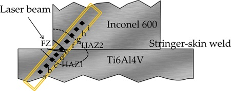
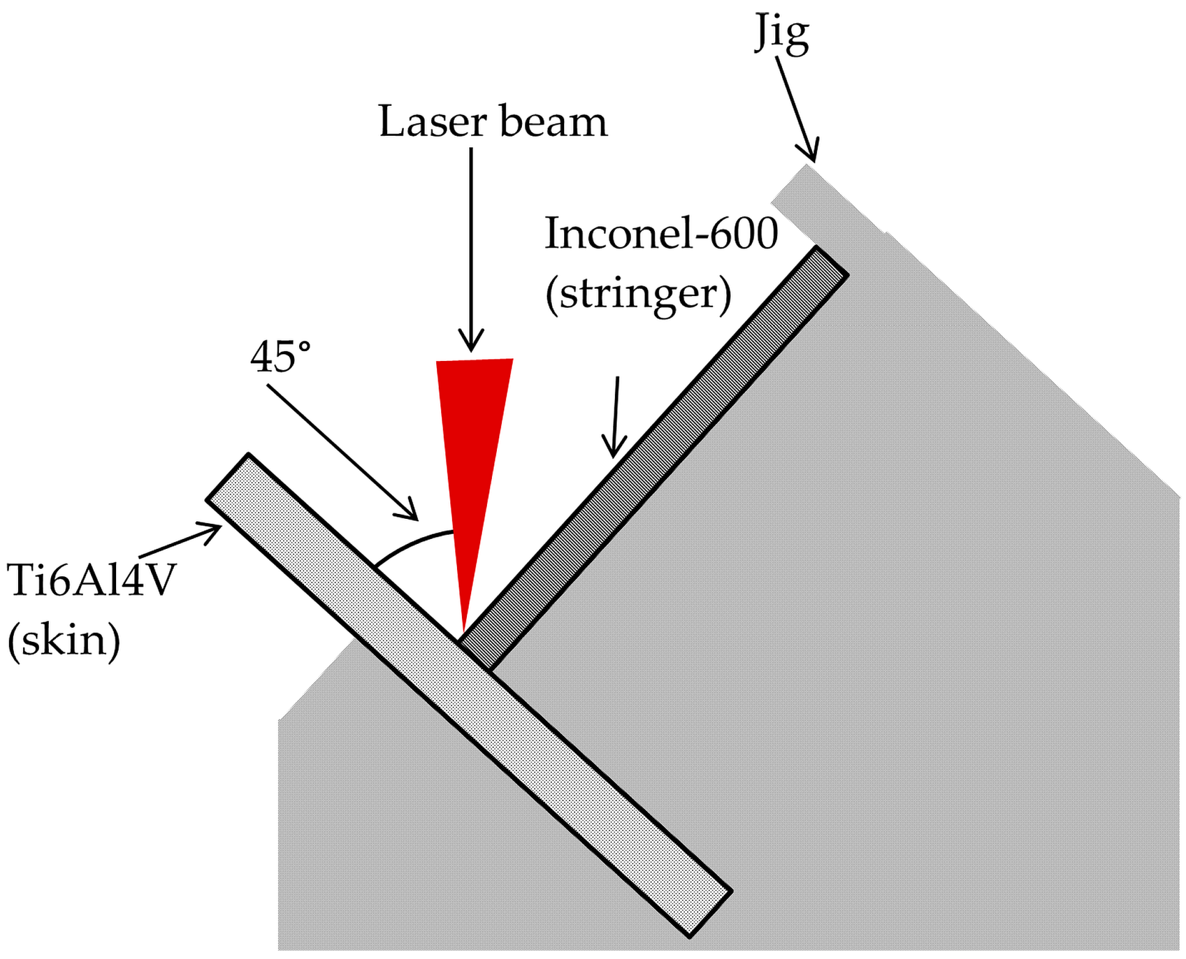
2.1. Materials and Sample Preparation

Inconel 600 sheets of 20 × 20 × 1 mm were used as stringers and Ti6Al4V sheets of 20 × 20 × 0.5 mm were used as skin in this study. The chemical composition of Inconel 600 and Ti6Al4V is presented in Table 1. Prior to laser welding, all the sheets were first mechanically polished using SiC abrasive paper (No. 600 grit size) to remove the cutting edge burr and then cleaned with acetone to remove any contaminants.

2.2. Laser Welding

A CW Ytterbium (Yb)-fiber laser with a 1070 nm emitting wavelength and 300 W maximum power output (Starfiber 300) was used in this study. The focal distance was kept constant at 346 mm between the scanner and the workpiece. The single-sided laser welding of these dissimilar work pieces was conducted in a T-joint configuration at a tilt angle of 45°. Figure 1 shows a schematic diagram of the experimental welding setup. The laser beam with 100 µm spot diameter hit the seam between the skin and the stringer, which was clamped in the T-joint configuration using a clamping fixture jig as shown in Figure 1. Argon was used as shielding gas to prevent oxidation of the weld surface during welding. Welding speed ranging between 40 and 50 mm/s and overlapping factor ranging between 30% and 50% were chosen as the parameters of interest in this study. The experiments were performed in two separate series to investigate their effects on weld quality. The detailed welding parameters are listed in Table 2.

2.3. Microstructural Characterization

After welding, the samples were cut perpendicular to the welding direction for metallographic analysis. After grinding and polishing, the samples were etched using Kroll’s reagent (92 mL distilled water, 6 mL nitric acid (HNO3) and 2 mL hydrofluoric acid (HF)) for 20 s at room temperature. The microstructures were observed using an optical microscope (OM, Olympus, Tokyo, Japan) and SEM (Phenom Pro X, Crest System (M) Sdn. Bhd., Eindhoven, The Netherlands), and the chemical composition of the weld bead cross sections was estimated by energy dispersive X-ray (EDX, Phenom Pro X, Crest System (M) Sdn. Bhd.,Eindhoven, The Netherlands). The SEM employed was equipped with EDX. The formation of intermetallic weld phases was characterized by X-ray diffraction (XRD, PaNalytical Empyrean, DKHS Holdings (Malaysia) Bhd., Almelo, The Netherlands) using CuKα radiation at 2θ diffraction angles ranging from 30° to 80°.

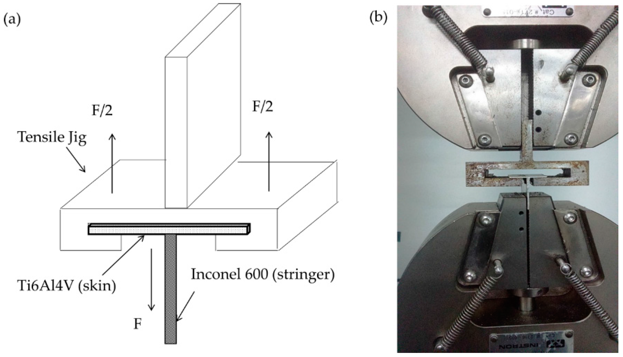
2.4. Pull Test Measurement

The pull method was utilized in this study to evaluate the force needed to break the joints and was carried out according to a previous study [19]. To execute the pull test, a customized jig was used to clamp the workpiece, as shown in Figure 2. The pull test was then performed using a universal testing machine (INSTRON, Model: 3369, Necomb Sdn. Bhd., Singapore) at room temperature with crosshead speed of 5 mm/min and 10 kN load cell. The results were determined from the average value of three different samples.

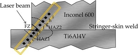
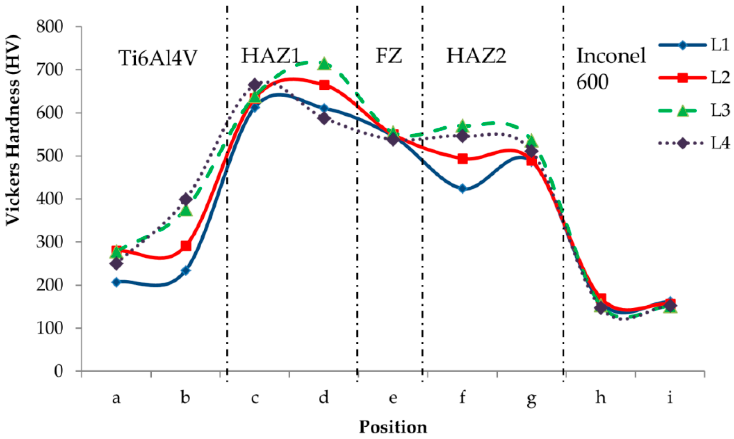
2.5. Vickers Microhardness Measurement

The Vickers microhardness profile, including of the BM, FZ and HAZ, was evaluated using a pyramidal diamond indenter (HMV 2T E, SHIMAZDU, Kyoto, Japan) with a load of 200 g for a dwell time of 5 s. Figure 3 schematically illustrates the hardness distribution profile of the weld geometry. Nine indentations at an indentation interval of 100 µm were performed perpendicular to the stringer-skin weld seam to investigate the FZ and each HAZ variation between the two dissimilar base metals.

3. Results and Discussion

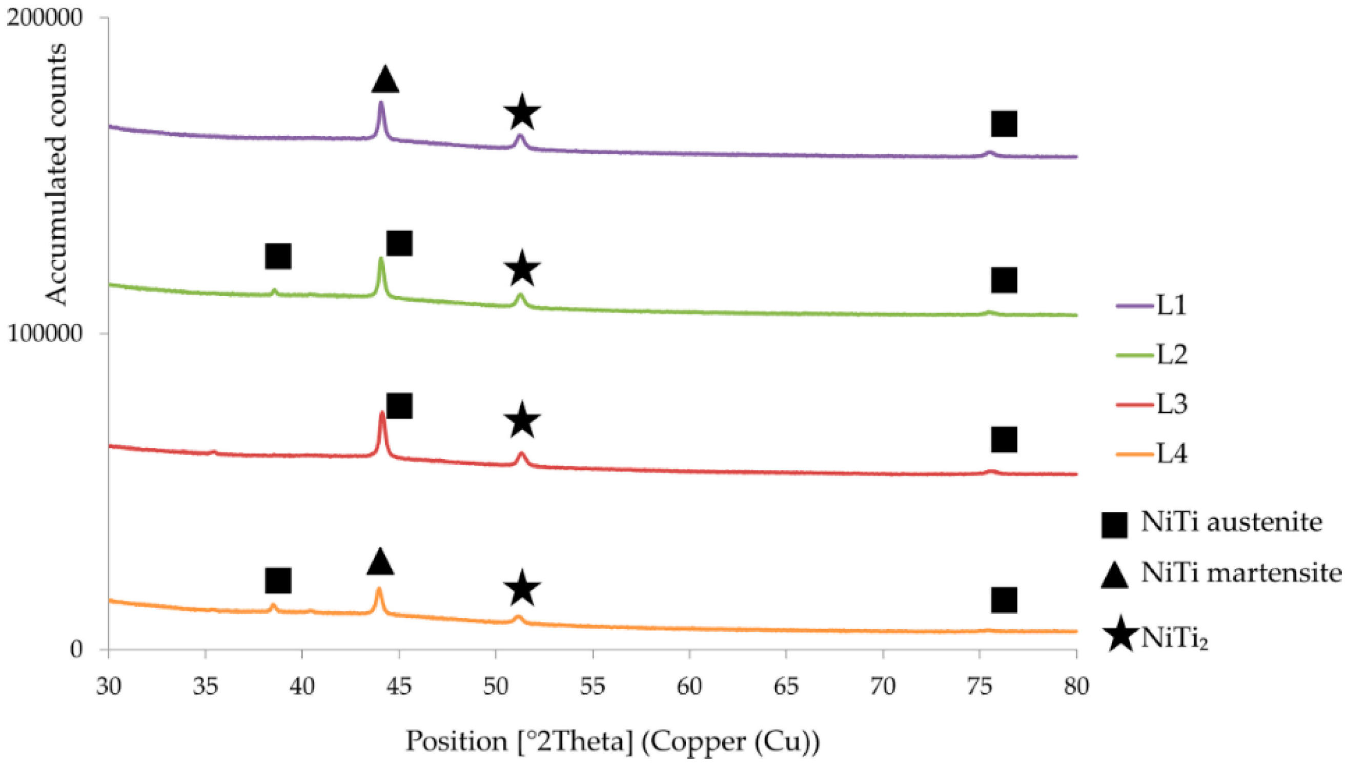
3.1. Metallurgical Characterization

In the present study, single-sided laser beam welding was performed on Inconel 600 and Ti6Al4V in a T-joint configuration. Optical micrographs for the weld bead cross-sections of all samples are presented in Figure 4. An asymmetric welding seam was observed in every sample because only one side was welded. The welded area where the laser beam was introduced exhibited a concave shape, whereas a slightly convex shape was observed in the non-welded area. This observation is typical for single-sided laser welding and has been reported in other studies [20]. As shown in Figure 4, the weld pools displayed a certain asymmetry and a greater extent of melting was observed on Ti6Al4V skin. This is because the thermal diffusivity of Ti alloy is lower than Ni alloy, resulting in localized heating and greater melting of Ti6Al4V during welding [9]. Moreover, the color of the Ti6Al4V base metal remained consistent for all samples, whereas color variation was observed on the Inconel 600 base metal from one sample to another, as indicated in Figure 4. The reason for this is that Kroll’s reagent is a recommended etchant for titanium alloys but not for nickel alloys. It has been reported that the nitric acid in Kroll’s reagent acts as an oxidizing agent and reacts with the nickel in Inconel 600 to produce Ni3+. Therefore, it can be inferred that the color variation of Inconel 600 is due to the intensity difference of Ni3+ production [18].
A sound joint was obtained when the welding speed was 40 mm/s and the overlapping factor was 50%. This is proven by the minor gap line of 0.202 mm indicated by sample L3 in Figure 4c. However, decreasing penetration depth and increasing gap line length were observed on the weld bead samples L1, L2 and L4, which possessed either lower overlapping factors or higher welding speeds. The gap lines were 0.637 mm, 0.527 mm and 0.422 mm long for samples L1, L2 and L4, respectively. Therefore, it can be concluded that the gap line length increased and the penetration depth decreased as the welding speed increased (comparing samples L3 and L4) while the overlapping factor decreased (comparing samples L1, L2 and L3).
As mentioned above, optimum welding was achieved for sample L3 because the heat input under this welding condition was sufficient to produce a sound T-joint with satisfactory penetration between the skin and stringer. It is reported that the amount of heat input determines the degree of dilution and cooling rate in the weld. Insufficient heat input during the welding process resulted in a faster cooling rate, thus causing limited melting between the skin and stringer and thereby leading to insufficient penetration. Heat input is critical in defining the joint’s geometry and can be manipulated by varying the welding parameters [21]. Among these, laser welding speed and the laser beam overlapping factor are commonly known as the most notable variables affecting the heat input. In this study, the heat input was calculated according to the following equation:
Heat Input   = P / [ π ( d η 2 ) 2 × v ]
where P = laser power, v = welding speed, d = beam diameter and η= overlapping factor.
Based on the equation above, it is proven that increasing the overlapping factor and decreasing the laser welding speed will increase the heat input on the workpiece. According to Figure 5, the affected areas are exposed to more accumulated heat input when the overlapping factor increases [22,23].

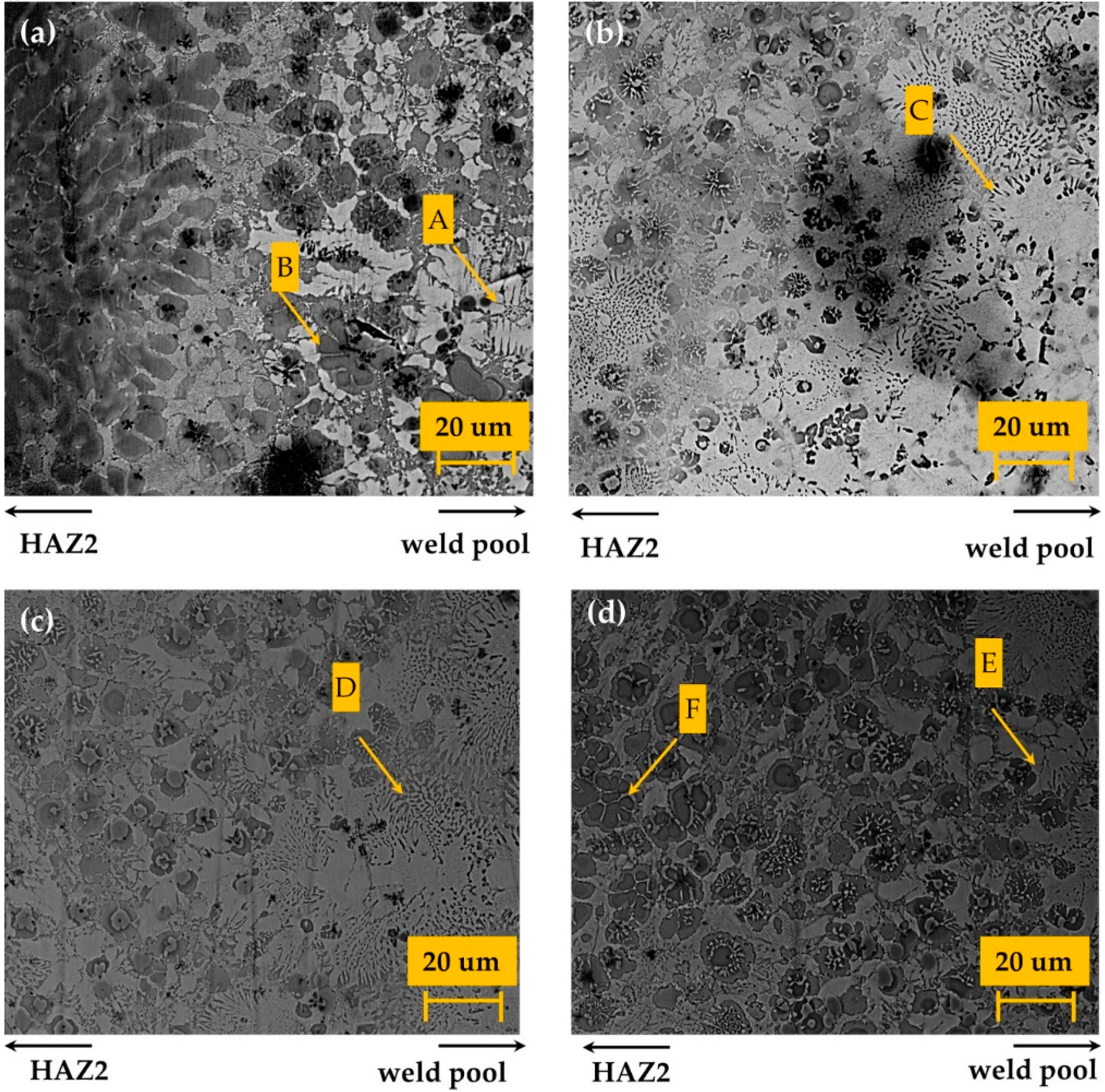
3.2. Microstructural Observation and Elemental Composition Analysis of the Weld Bead

Figure 6 shows the microstructure of the interface between the FZ and HAZ of Ti6Al4V (denoted as HAZ1) and Inconel 600 (denoted as HAZ2) cross-sections of sample L3. The grains become notably finer in HAZ compared to those in the base metals, indicating a large thermal gradient at the FZ and HAZ interface during the laser welding process. Such a phenomenon can be attributed to rapid solidification, whereby the grain size in the microstructure is rather small in the laser-affected areas and surroundings [24]. At FZ, an equiaxed pattern was observed as grain sizes were smaller due to rapid melting and solidification. The fusion zone had a similar identification of columnar beta grains of Ti that occurred during two-dimensional heat flow condition [25].
Figure 7 shows the presence of NiTi and NiTi2 microstructures, proving the formation of these phases between Ni base alloy and Ti base alloy during laser welding. This observation is further corroborated by the EDX analysis displayed in Table 3, where the atomic percentage of Ni and Ti for each sample was determined. According to the Ni–Ti phase diagram, the NiTi phase was produced in primary crystallization from the melt, whereas the NiTi2 phase was formed by peritectic reaction between the NiTi phase and the cooling after NiTi columnar dendrite melting [26]. Points A, C, D and E had nearly the same percentage of Ni and Ti, proving NiTi was present, while point B and F showed that the ratio of Ti to Ni was 2:1, indicating the presence of NiTi2. As displayed in Figure 7, NiTi2 was only detected near the weld pool for samples L1 and L4 due to the lower heat input that allowed the phase formation. Meanwhile, NiTi was detected in all samples, as shown in Figure 7. The results obtained are similar to the study done by Chatterjee et al. who investigated the microstructural development of NiTi and NiTi2 during dissimilar metal welding of Ti and Ni [12]. The phases were detected at the weld pool beside the HAZ of Inconel 600. The formation of these intermetallic phases is reportedly attributed to the crystallographic mismatch between Ni and Ti.
The Ti–Ni system had different conductivities of κNi ≈ 4κTi, resulting in a Ti-rich melt pool combined with metallurgical dissimilarity. Due to the differences in thermal diffusivity and conductivity, Ti from Ti6Al4V flowed towards the weld pool and reacted with Ni from Inconel. This resulted in inhomogeneous molten flow (Ti-rich melt pool) and asymmetric heat transfer during the welding process, contributing to the formation of these intermetallic phases due to metallurgical dissimilarity as shown in the phase diagram of Ti–Ni [9]. NiTi is reportedly being more erosion-resistant than stainless steels [27,28]. Therefore, the presence of NiTi as an intermetallic compound in the weld zone is an advantage in improving the joining properties. During dissimilar laser welding of titanium alloy and nickel alloy, base metal grains grew into the welding pool. A steep composition gradient was observed at the interface. NiTi and NiTi2 dendrites grew to form a band at the HAZ. The NiTi liquidus line had a steeper slope compared to NiTi2, suggesting the latter is likely to form heterogeneously. According to the phase diagram, both NiTi and NiTi2 constituted the bulk of the weld microstructure. The microstructures may have been caused by the precipitation of NiTi2 from the rich Ti β2 phase and entrapment due to growing NiTi dendrites. This particle can nucleate before NiTi in certain circumstances [29].
The XRD analysis indicated that NiTi and NiTi2 formed in the FZ and HAZ. The NiTi2 phase is not recommended in large quantities, because it can lead to a strong tendency of hot cracking, which is prone to cause weaker joints [9,15,16,29]. From Figure 8 it can be seen that the high-temperature B2 phase (austenite) from NiTi was found in samples L2 and L3, which further changed to low-temperature B19’ phase (martensite) when the overlapping factor was 30% for sample L1, and the welding speed increased to 50 mm/s for sample L4. The amount of NiTi also decreased when the welding speed increased (L4) and the overlapping factor reduced (L1). Based on the XRD analysis, NiTi2 formed in all samples. However, the peak NiTi2 was detected only in L1 and L4. This may be related to the peritectic reaction that did not occur in samples L2 and L3. At lower heat input where shorter heating and cooling time are needed for laser welding, the penetration of Ni from Inconel 600 was insufficient, resulting in the XRD peak of NiTi2 and martensitic phase of NiTi. However, with higher heat input and slightly longer welding time, the penetration of Ni from Inconel 600 was sufficient, thus causing the XRD peak of the NiTi austenitic phase to become more apparent [27]. This was proven by the increased number of NiTi counts with the increasing overlapping factor, whereas the NiTi count reduced when laser welding speed increased. The changes in XRD counts show the differences clearly. Similar phases were detected in related studies done by other researchers, proving that the X-ray beam hit the welded area [9,27]. However, limited peaks were found during XRD, indicating a tentative phase indexation of these phases. The overlapping factor and laser welding speed clearly affected the microstructural properties of the weld joint.

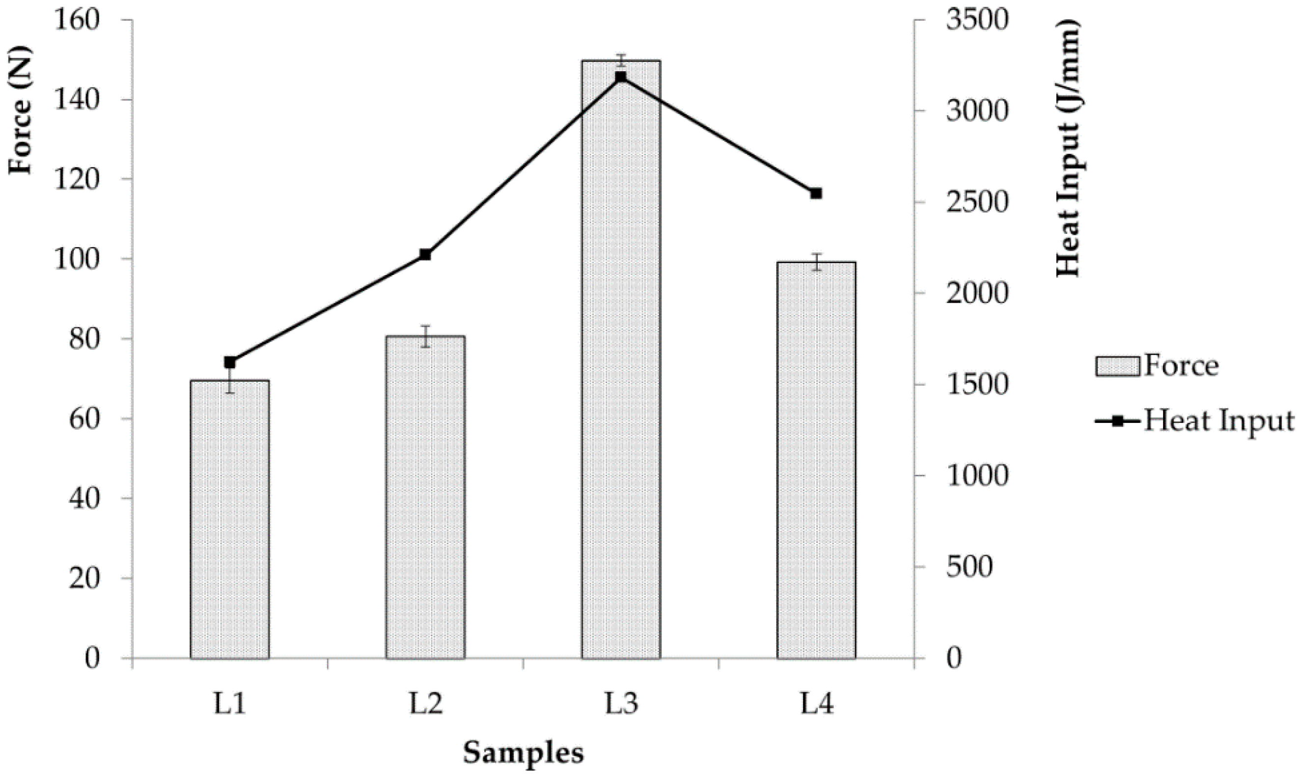
3.3. Characterization of Mechanical Properties

The effects of the overlapping factor and welding speed on the breaking force (the force needed to fracture samples) of the weld beads are presented in Figure 9. By comparing samples L1, L2 and L3, it was noted that the breaking force increased by increasing the overlapping factor. However, the opposite trend was observed when studying the effect of welding speed, where the breaking force decreased with increasing welding speed as seen for samples L3 and L4. In the present study, the maximum force of 150 N was achieved in sample L3 when the overlapping factor was 50% and the welding speed was 40 mm/s at a given constant power of 250 W. The increase was mainly because the laser welding at higher overlapping factor or lower welding speed induced greater heat input and thus a wider fusion zone with deeper penetration that required higher breaking force. The results are in accordance with the results obtained from metallurgical characterization, indicating that heat input was the main factor affecting the geometry and breaking force of the weld joint [27].
Figure 10 depicts the effects of the overlapping factor and welding speed on the hardness distribution of the welded bead. The hardness was studied across the entire profile of the weld bead (including base metal, heat-affected zone and fusion zone). The hardness of Inconel 600 base material was around 140–160 HV, whereas the hardness of Ti6Al4V base material was around 260–300 HV. As the overlapping factor increased, the FZ and HAZ hardness increased. The hardest sample was achieved at a welding speed of 40 mm/s and overlapping factor of 50%. The hardness at HAZ1 was higher than HAZ2, as the HAZ1 was closer to the Ti6Al4V base material that had higher hardness. As shown in Figure 10, sample L3 displayed the highest hardness among its counterparts with 554 HV at FZ, 715 HV at HAZ1 and 570 HV at HAZ2. This is attributed to the presence of NiTi, as the Vickers hardness of NiTi alloy reportedly ranges between 380 and 440 HV [30]. Both skin and stringers in this study were annealed by undergoing heat treatment. When welding in this condition, there is a possibility that micro fissures will form in the HAZ region due to the coarser grains formed. The measured FZ region hardness was higher than the base metals. Meanwhile, the hardness in the HAZ region was even higher than the FZ region. The hardness of the FZ region was observed to be lower than the HAZ region, as shown in Figure 10. This was a result of the higher amount of molten metal in FZ due to the lack of precipitation strengthening caused by particles dispersing from the precipitate. A hardness transition between FZ and the base metal occurred and the HAZ region measured the highest hardness among the three regions. Other comparable studies have been done, where similar areas were indicated for hardness measurement [31].

4. Conclusions

According to the experimental results reported in this study, it can be concluded that:
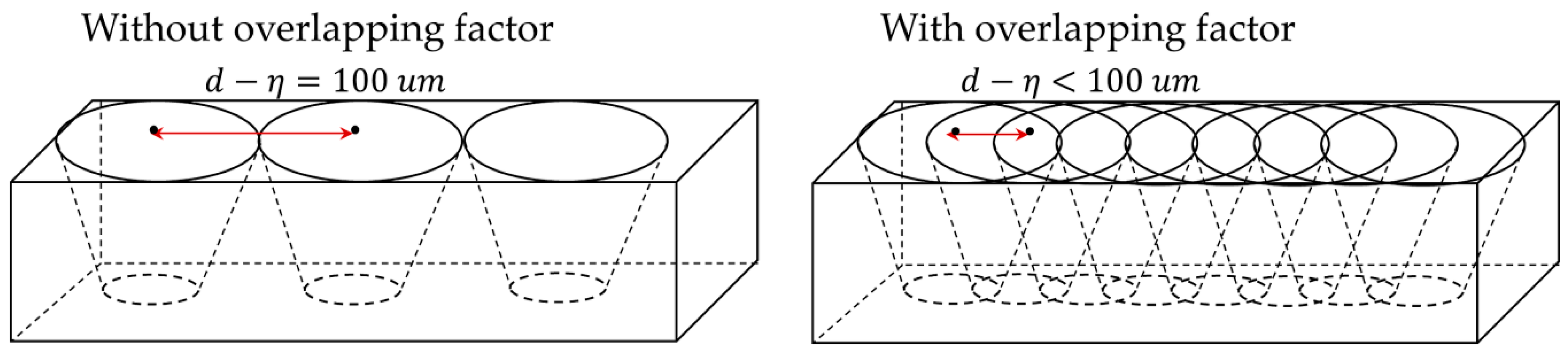
  • Single-sided laser welding was successfully performed on thin sheets of Ti6Al4V and Inconel 600 in a T-joint configuration using low-power Ytterbium-fiber laser with the influence of laser welding speed and the overlapping factor.
  • The highest breaking force and hardness were obtained when the welding speed was 40 mm/s and the overlapping factor was 50% at laser power of 250 W, proving a sound joint was obtained because sufficient heat input was produced.
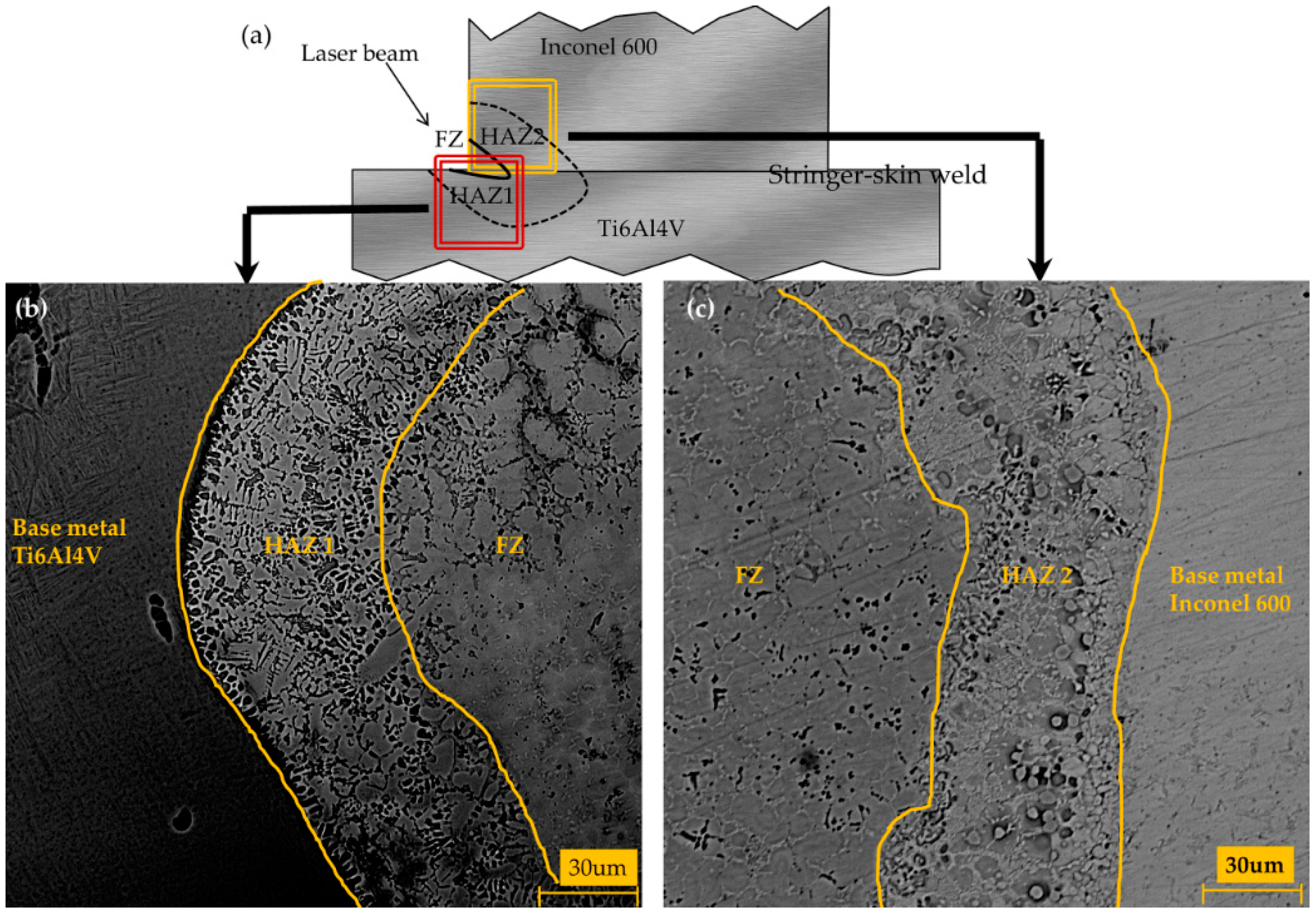
  • NiTi and NiTi2 intermetallic layers formed in the FZ and HAZ regions due to crystallographic mismatch between Ni and Ti as well as the differences in thermo-physical properties of the materials.
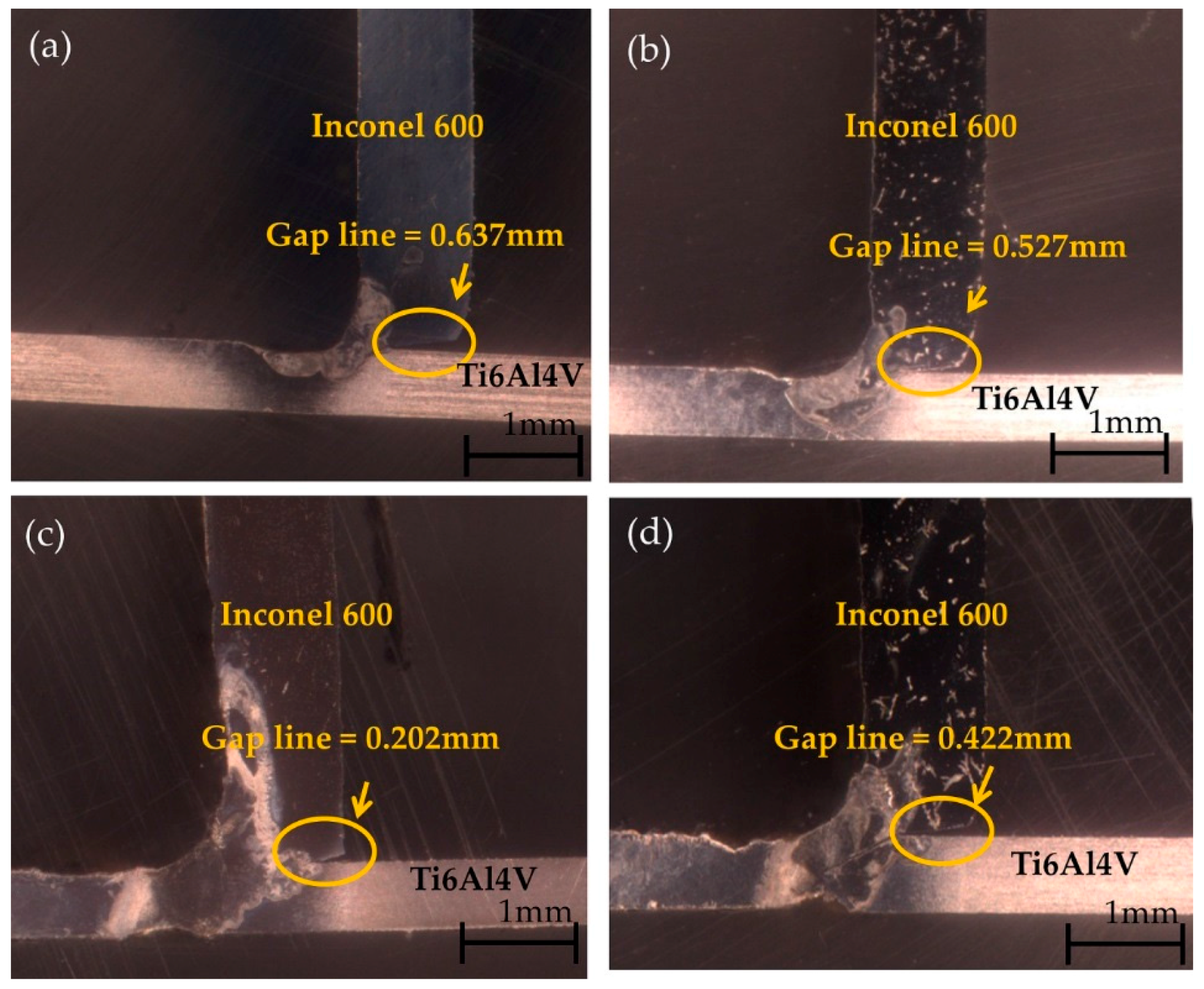
  • The extent of skin-stringer penetration was related to the heat input, which was manipulated by varying the laser welding speed and overlapping factor.

Acknowledgments

The authors greatly acknowledge University of Malaya for providing the necessary facilities and resources for this research. This research is funded by the Postgraduate Research Fund (PPP) with Grant No: PG001-2013A and University Malaya Research Grant (UMRG) with Grant No.: RP010A-13AET. Authors would like to acknowledge Mr Zaharudin Md Salleh from Geology Department and Madam Hartini Baharum from Engineering Faculty for their support in laboratory works.

Author Contributions

Shamini Janasekaran conducted and analyzed the experiments, and wrote the article. Ai Wen Tan contributed by analyzing data and revising the writing. Farazila Yusof and Mohd Hamdi Abdul Shukor supervised the work and further analyzed the data.

Conflicts of Interest

The authors declare no conflict of interest.

Abbreviations

The following abbreviations were used in this manuscript:
SEM
Scanning electron microscopy
XRD
X-ray diffraction
LBW
Laser beam welding
BM
Base metal
CW
Continuous wave
FZ
Fusion zone
HAZ
Heat-affected zone
TIG
Tungsten inert gas
MIG
Metal inert gas
Ti
Titanium
Ni
Nickel
Yb
Ytterbium
HNO3
Nitric acid
HF
Hydrofluoric acid
OM
Optical microscope
EDX
Energy dispersive X-ray

References

  1. Shokrani, A.; Dhokia, V.; Newman, S.T. Environmentally conscious machining of difficult-to-machine materials with regard to cutting fluids. Int. J. Mach. Tool. Manuf. 2012, 57, 83–101. [Google Scholar] [CrossRef] [Green Version]
  2. Chen, H.C.; Pinkerton, A.J.; Li, L. Fibre laser welding of dissimilar alloys of Ti–6Al–4V and inconel 718 for aerospace applications. Int. J. Adv. Manuf. Technol. 2011, 52, 977–987. [Google Scholar] [CrossRef]
  3. Mavrigian, M. Performance Exhaust Systems: How to Design, Fabricate, and Install; CarTech Inc.: North Branch MN, USA, 2014; p. 144. [Google Scholar]
  4. Shen, Y.; Liu, Y.; Sun, W.; Dong, H.; Zhang, Y.; Wang, X.; Zheng, C.; Ji, R. High-speed dry compound machining of Ti6Al4V. J. Mater. Process. Technol. 2015, 224, 200–207. [Google Scholar] [CrossRef]
  5. Warwick Manufacturing Group. Off to the races. Met. Powder Rep. 2012, 67, 22–24. [Google Scholar]
  6. Welding exhaust systems—part 1. Available online: http://www.burnsstainless.com/weldingarticle1.aspx (accessed on 12 April 2016).
  7. Guo, J.F.; Chen, H.C.; Sun, C.N.; Bi, G.; Sun, Z.; Wei, J. Friction stir welding of dissimilar materials between AA6061 and AA7075 Al alloys effects of process parameters. Mater. Des. 2014, 56, 185–192. [Google Scholar] [CrossRef]
  8. Kurakake, Y.; Farazila, Y.; Miyashita, Y.; Otsuka, Y.; Mutoh, Y. Effect of molten pool shape on tensile shear strength of dissimilar materials laser spot joint between plastic and metal. J. Laser Micro Nanoeng. 2013, 8, 161–164. [Google Scholar] [CrossRef]
  9. Chatterjee, S.; Abinandanan, T.A.; Chattopadhyay, K. Phase formation in Ti/Ni dissimilar welds. Mater. Sci. Eng. A 2008, 490, 7–15. [Google Scholar] [CrossRef]
  10. Schubert, E.; Klassen, M.; Zerner, I.; Walz, C.; Sepold, G. Light-weight structures produced by laser beam joining for future applications in automobile and aerospace industry. J. Mater. Process. Technol. 2001, 115, 2–8. [Google Scholar] [CrossRef]
  11. Seretsky, J.; Ryba, E. Laser-welding of dissimilar metals—Titanium to nickel. Weld. J. 1976, 55, 208–211. [Google Scholar]
  12. Chatterjee, S.; Abinandanan, T.A.; Chattopadhyay, K. Microstructure development during dissimilar welding: Case of laser welding of Ti with Ni involving intermetallic phase formation. J. Mater. Sci. 2006, 41, 643–652. [Google Scholar] [CrossRef]
  13. Carpinteri, A.; Brighenti, R.; Huth, H.J.; Vantadori, S. Fatigue growth of a surface crack in a welded T-joint. Int. J. Fatigue 2004, 27, 59–69. [Google Scholar] [CrossRef]
  14. Padovani, C.; Fratini, L.; Squillace, A.; Bellucci, F.E. Electrochemical analysis on friction stir welded and laser welded 6xxx aluminium alloys t-joints. Corros. Rev. 2007, 25, 475–489. [Google Scholar] [CrossRef]
  15. Oliveira, J.P.; Panton, B.; Zeng, Z.; Andrei, C.M.; Zhou, Y.; Miranda, R.M.; Fernandes, F.M.B. Laser joining of niti to Ti6Al4V using a niobium interlayer. Acta Mater. 2016, 105, 9–15. [Google Scholar] [CrossRef]
  16. Miranda, R.M.; Assunção, E.; Silva, R.J.C.; Oliveira, J.P.; Quintino, L. Fiber laser welding of NiTi to Ti–6Al–4V. Int. J. Adv. Manuf. Technol. 2015, 81, 1533–1538. [Google Scholar] [CrossRef]
  17. Fratini, L.; Buffa, G.; Shivpuri, R. Influence of material characteristics on plastomechanics of the fsw process for T-joints. Mater. Des. 2009, 30, 2435–2445. [Google Scholar] [CrossRef]
  18. Rebak, R.B.; Crook, P. Nickel alloys for corrosive environments. Adv. Mater. Process. 2000, 157, 37. [Google Scholar]
  19. Badini, C.; Pavese, M.; Fino, P.; Biamino, S. Laser beam welding of dissimilar aluminium alloys of 2000 and 7000 series: Effect of post-welding thermal treatments on T joint strength. Sci. Technol. Weld. Join. 2009, 14, 484–492. [Google Scholar] [CrossRef]
  20. Enz, J.; Khomenko, V.; Riekehr, S.; Ventzke, V.; Huber, N.; Kashaev, N. Single-sided laser beam welding of a dissimilar AA2024-AA7050 T-joint. Mater. Des. 2015, 76, 110–116. [Google Scholar] [CrossRef]
  21. Unt, A.; Salminen, A. Effect of welding parameters and the heat input on weld bead profile of laser welded T-joint in structural steel. J. Laser Appl. 2015, 27. [Google Scholar] [CrossRef]
  22. Ribic, B.; Palmer, T.A.; DebRoy, T. Problems and issues in laser-arc hybrid welding. Int. Mater. Rev. 2009, 54, 223–244. [Google Scholar] [CrossRef]
  23. Gao, X.L.; Liu, J.; Zhang, L.J.; Zhang, J.X. Effect of the overlapping factor on the microstructure and mechanical properties of pulsed Nd:Yag laser welded Ti6Al4V sheets. Mater. Character. 2014, 93, 136–149. [Google Scholar] [CrossRef]
  24. Norris, J.T.; Robino, C.V.; Hirschfeld, D.A.; Perricone, M.J. Effects of laser parameters on porosity formation: Investigating millimeter scale continuous wave Nd:Yag laser welds. Weld. J. 2011, 90, 198. [Google Scholar]
  25. Donachie, M.J. Titanium: A Technical Guide; ASM International: Novelty, OH, USA, 2000; p. 381. [Google Scholar]
  26. Sudarshan, T.S. Surface Modification Technologies: Proceedings of the 20th International Conference on Surface Modification Technologies; ASM International: Vienna, Austria, 2007. [Google Scholar]
  27. Hiraga, H.; Inoue, T.; Shimura, H.; Matsunawa, A. Cavitation erosion mechanism of niti coatings made by laser plasma hybrid spraying. Wear 1999, 231, 272–278. [Google Scholar] [CrossRef]
  28. Richman, R.H.; Rao, A.S.; Kung, D. Cavitation erosion of NiTi explosively welded to steel. Wear 1995, 181–183, 80–85. [Google Scholar] [CrossRef]
  29. Kocich, R.; Szurman, I.; Kursa, M. The methods of preparation of Ti–Ni–X alloys and their forming. In Shape Memory Alloys-Processing, Characterization and Applications; Fernandes, F.M.B., Ed.; Press: Ostrava, Czech Republic, 2013. [Google Scholar]
  30. Brantley, W.A.; Eliades, T. Orthodontic Materials: Scientific and Clinical Aspects; Thieme: Stuttgart, Germany, 2011. [Google Scholar]
  31. Atabaki, M.M.; Nikodinovski, M.; Chenier, P.; Ma, J.; Liu, W.; Kovacevic, R. Experimental and numerical investigations of hybrid laser arc welding of aluminum alloys in the thick T-joint configuration. Opt. Laser Technol. 2014, 59, 68–92. [Google Scholar] [CrossRef]
Figure 1. Schematic diagram of the welding experiment setup.
Metals 06 00134 g001
Figure 2. (a) Schematic diagram of tensile pull test for the T-joint configuration of Inconel 600 and Ti6Al4V; (b) Customized jig for tensile pull test.
Metals 06 00134 g002
Figure 3. Schematic diagram of hardness distribution on the weld geometry.
Metals 06 00134 g003
Figure 4. Optical micrographs of samples (a) L1; (b) L2; (c) L3 and (d) L4.
Metals 06 00134 g004
Figure 5. Schematic diagram showing the effect of the overlapping factor on the laser-irradiated area.
Metals 06 00134 g005
Figure 6. (a) Schematic diagram of FZ, HAZ1, HAZ2 and base of sample, SEM micrographs of microstructure sample; (b) L3 for FZ, HAZ1 and base metal, Ti6Al4V (c) L3 for FZ, HAZ2 and base metal, Inconel 600.
Metals 06 00134 g006
Figure 7. SEM micrographs of NiTi and NiTi2 intermetallic phases formed in the FZ at samples (a) L1; (b) L2; (c) L3 and (d) L4.
Metals 06 00134 g007
Figure 8. XRD patterns of samples L1, L2, L3 and L4.
Metals 06 00134 g008
Figure 9. Force needed to fracture the samples and heat input for samples L1, L2, L3 and L4.
Metals 06 00134 g009
Figure 10. Vickers microhardness profiles of all samples.
Metals 06 00134 g010
Table 1. Chemical composition of Inconel 600 and Ti6Al4V (wt. %) [18].
ElementTi6Al4VInconel 600
Ni-72 min
Cr-14.0–17.0
Cu-0.5 max
S-0.015 max
Si-0.5 max
C0–0.080.05–0.10
Fe0–0.46.0–10.0
TiBalance-
Al5.5–6.75-
V3.5–4.5-
Table 2. Welding parameters used in the study.
SamplePower (W) PWelding Speed (mm/s) vOverlapping Factor (%) η
L12504030
L22504040
L32504050
L42505050
Table 3. The element atomic percentage in L1, L2, L3 and L4.
PointNi (at. %)Ti (at. %)V (at %)Al (at. %)Cr (at. %)Fe (at. %)Total (%)Phase
A39.540.53.45.47.73.5100.0NiTi
B28.456.43.35.33.63.0100.0NiTi2
C42.138.93.24.08.33.5100.0NiTi
D40.540.93.53.98.13.1100.0NiTi
E39.440.63.34.47.64.7100.0NiTi
F29.155.43.56.03.32.7100.0NiTi2

