Article

Multi-Track Friction Stir Lap Welding of 2024 Aluminum Alloy: Processing, Microstructure and Mechanical Properties

1
School of Mechanical Engineering, Beijing Institute of Technology, Beijing 100081, China
2
Beijing Aeronautical Science & Technology Research Institute of COMAC, Beijing 102211, China
*
Author to whom correspondence should be addressed.
Metals 2017, 7(1), 1; https://doi.org/10.3390/met7010001
Submission received: 18 September 2016 / Revised: 15 December 2016 / Accepted: 16 December 2016 / Published: 22 December 2016

Abstract

:
Friction stir lap welding (FSLW) raises the possibility of fabricating high-performance aluminum components at low cost and high efficiency. In this study, we mainly applied FSLW to fabricate multi-track 2024 aluminum alloy without using tool tilt angle, which is important for obtaining defect-free joint but significantly increases equipment cost. Firstly, systematic single-track FSLW experiments were conducted to attain appropriate processing parameters, and we found that defect-free single-track could also be obtained by the application of two-pass processing at a rotation speed of 1000 rpm and a traverse speed of 300 mm/min. Then, multi-track FSLW experiments were conducted and full density multi-track samples were fabricated at an overlapping rate of 20%. Finally, the microstructure and mechanical properties of the full density multi-track samples were investigated. The results indicated that ultrafine equiaxed grains with the grain diameter about 9.4 μm could be obtained in FSLW samples due to the dynamic recrystallization during FSLW, which leads to a yield strength of 117.2 MPa (17.55% higher than the rolled 2024-O alloy substrate) and an elongation rate of 31.05% (113.84% higher than the substrate).

1. Introduction

With the increasing requirements of lightweight and economization in many manufacturing industries, aluminum alloys have gradually replaced iron alloys as the most widely used metal material, because of their excellent characteristics such as high crustal content, high specific strength, good machining property, and so on [1]. As a typical high strength aluminum alloy, 2024 aluminum alloy has been gaining commercial importance in aerospace, automotive, and other industries [2]. Increasing interest has been placed on high strength aluminum alloys, apparently due to their combined advantage of strength and lightweight. It is well known that aluminum alloys are difficult to join by fusion welding techniques because of their hot cracking sensitivity, especially for some aluminum alloys with precipitation hardening (such as 2XXX and 7XXX series aluminum alloys). Therefore, for aluminum components fabricated by fusion based welding process, the major concerns include porosity, coarse grains and other solidification related defects [2].
Friction stir lap welding (FSLW) is a solid-state processing technique based on the principle of friction stir welding (FSW). FSLW has a huge potential to fabricate aluminum components with high mechanical performances [3]. The FSLW process is schematically shown in Figure 1. A non-consumable rotating tool with custom-designed pin and shoulder is inserted into the overlapping surfaces of plates, and subsequently traversed along the configured joint line. This makes the plates join together. Compared with other metal welding technologies, FSLW does not have an independent heat source, because the necessary heat to weld aluminum substrates is provided by the frictional heat between the rotating tool and work piece. The frictional heat is controlled by changing the process parameters. During the whole FSLW process, the welding temperature is controlled to be below the melting point of the material. Therefore, the metal substrates are plasticized instead of melting in the FSLW process. It can efficiently avoid all solidification defects. The plasticized materials are extruded from the advancing side to the retreating side under the action of the rotation and the traverse movement of the pin. The weld nugget is formed under the axial pressure provided by the shoulder.
Friction stir welding has been studied intensively in recent years due to its importance in industrial applications [4,5,6]. The majority of these studies have been based on butt joint configuration, and friction stir lap welding has received considerably less attention [7]. Limited articles related to FSLW were provided by few researchers. For example, Zhang et al. [8] have studied the effect of welding speed on mechanical performance of friction stir lap welded 7B04 aluminum. Ghosh et al. [9] have studied the microstructure and mechanical properties of high strength steels FSLW under different heat input and cooling rates. However, almost all these FSLW studies focus on single-track processing. Multi-track FSLW has potential to fabricate large-scale aluminum monolithic components. It is also the key technology for the friction stir additive manufacturing (FSAM), which is an important direction for the development of friction stir technology [10,11,12]. On the other hand, the tilt angle is normally adopted in these reports about FSLW, because tilt angle is widely believed to be an important processing parameter to obtain defect-free joint for friction stir technologies [13,14,15]. Considering that the tilt angle must maintain the same direction as the processing direction, using tilting angle introduces significant complications in processing path and equipment cost. Therefore, it is meaningful to explore the multi-track FSLW processing without tilt angle.
In this study, the formation characters, microstructure and mechanical properties of the multi-track 2024 aluminum alloy specimen are investigated based on the improved FSLW technique without tilt angle.

2. Experimental Procedures

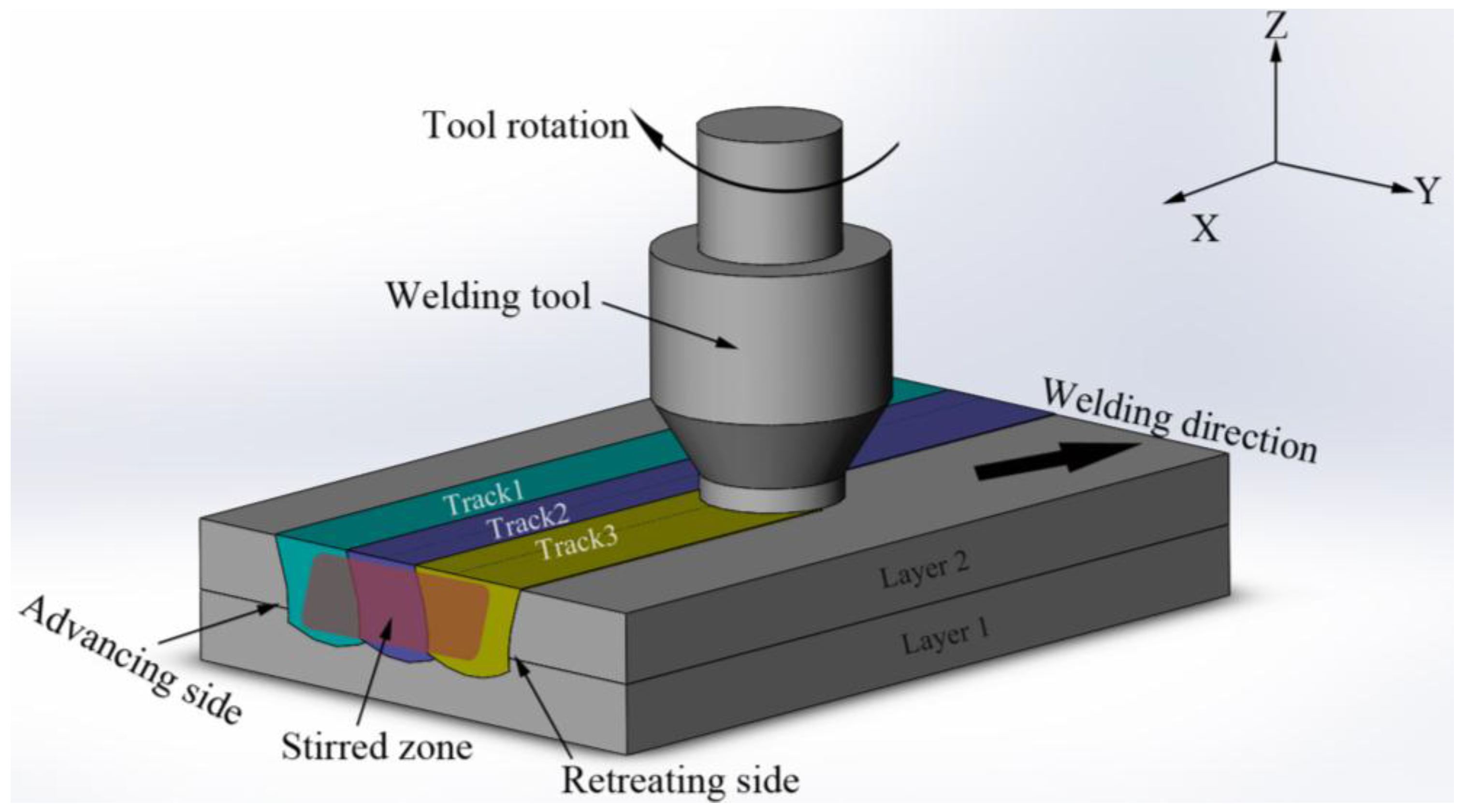
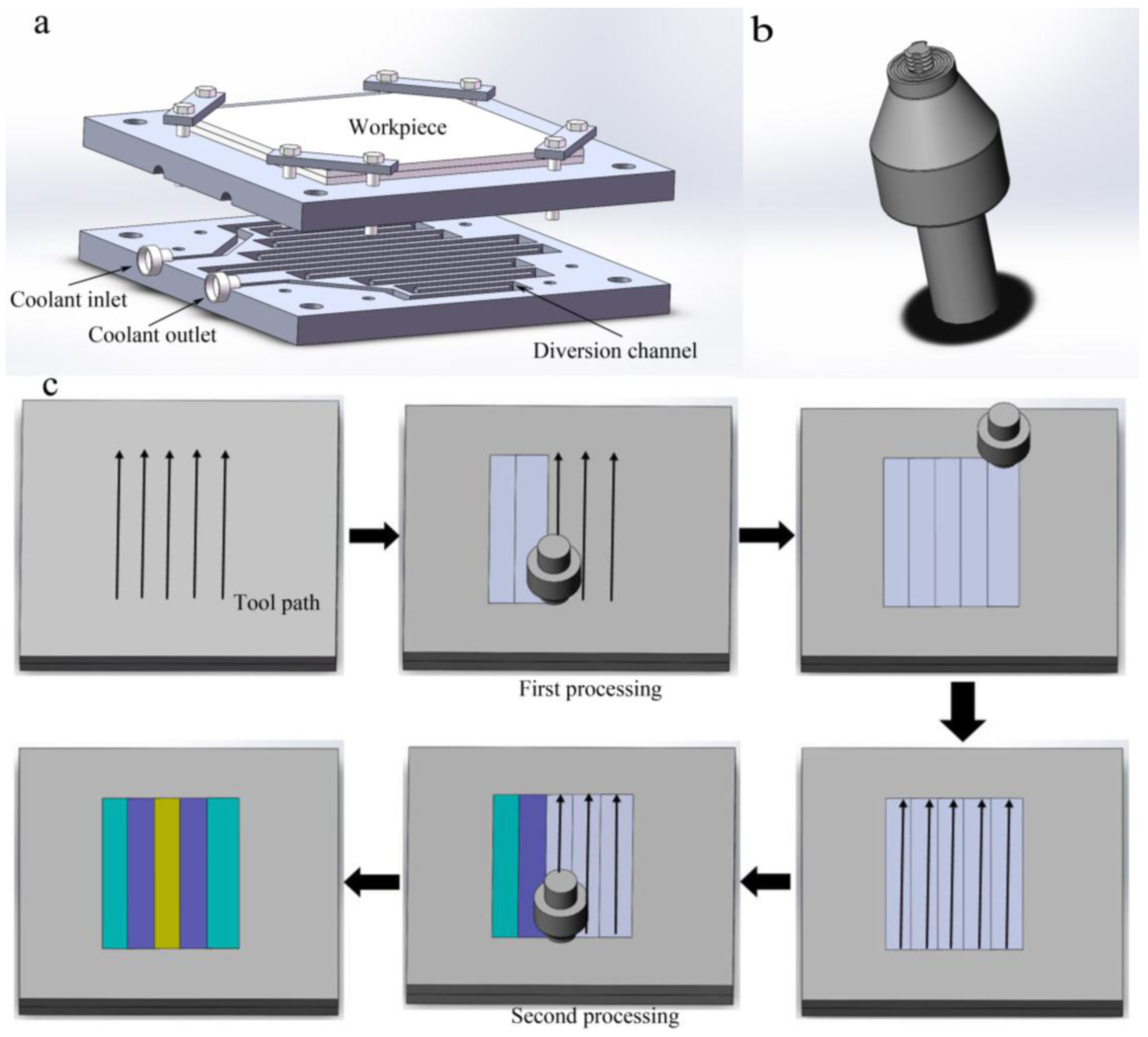
2.1. Experimental Setup and Manufacturing Process

The substrates used in this study were rolled 2024 aluminum alloy plates with 5-mm thickness in annealed condition (2024-O). According to the experimental requirements, the plates with a size of 200 × 200 × 5 mm are used for multi-track FSLW on a modified machining center (Maker: Makino, Tokyo, Japan; Model: FNC-86). Strict clamping and temperature sensitivity are two challenging points of friction stir technology. Therefore, a fixture with circulating liquid cooling was designed in this study for firm clamping and cooling. The schematic diagram of clamping was shown in Figure 2a. The welding tool is the most important part in FSLW, which provides the required heat and pressure for forming. As shown in Figure 2b, the tool used in this study was made of H13 tool steel with a left cylindrical threaded pin. The end surface of shoulder consists of concentric rings with decreasing height from outside to inside. The surface presents concave-shape in general. The shoulder diameter is 20 mm, and the pin diameter and pin height are 8 and 6 mm, respectively. In order to increase the flowability of plastic material, the pin was provided with three slots.
It is well known that friction stir welding and related technologies are sensitive to the variation of parameters. Therefore, systematic experimental studies were conducted to get appropriate parameters, as shown in Table 1. Based on these test experiments, a rotation speed of 1000 rpm, a traverse speed of 300 mm/min and a plunge depth of 0.2 mm were adopted. More specific analysis was presented in Section 3.1.1 of this article.
In particular, the tilt angle was not used in order to reduce the cost of equipment and avoid the difficulty in controlling tilt angle direction during the forming process. The detailed reason why controlling tilt angle can be avoided is discussed in detail in Section 3.1.2 of this article. According to the results above, the main FSLW parameters used in this study are shown in Table 2.
Finally, a multi-tracked build is obtained with an effective width of about 38 mm (see Figure 3a), and the experimental simulation diagram of experimental procedure is shown in Figure 2c.

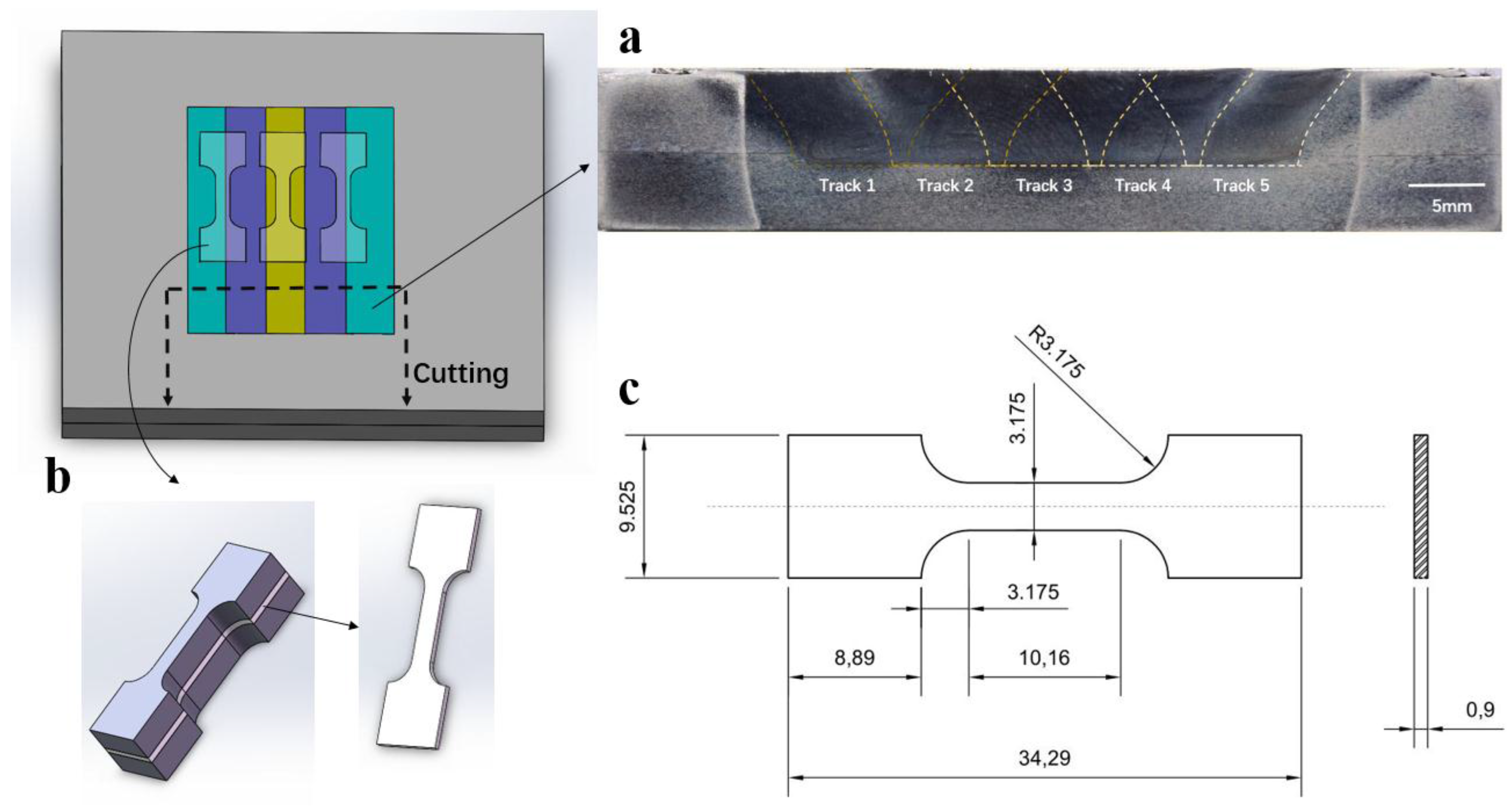
2.2. Microstructural Characterization and Mechanical Testing

With respect to the microstructural characterization and secondary phase particles analysis, the specimens were cross-sectioned perpendicular to the welding direction and suffered grinding following a standard metallographic process as shown in Figure 3a. Because the microstructure in the near surface region (such as the grain morphology of 2024 after FSLW) is difficult to observe, both mechanical polishing and electrochemical polishing were taken to obtain a higher surface quality. The electrochemical polishing was performed at a temperature of −15 °C and a voltage of 20 V for 16 s with the chemical solution composed by 10% perchloric acid and 90% alcohol. Then, the specimens were etched in a mixture of 10 mL nitric acid, 6 mL hydrochloric acid, 4 mL hydrofluoric acid, and 180 mL water for duration of 30 s. The microstructures of specimens were characterized by optical microscopy (Maker: Leica, Wetzlar, Germany; Model: Leica DM4000M). The secondary phase particles and the fracture surfaces of the tensile samples were analyzed by scanning electron microscope (SEM, JEOL, Tokyo, Japan; Model: JSM-6610LV).
Figure 3b presents the manufacturing procedure of the tensile specimens. These specimens were cut from the middle parts of the plates along the welding direction and then machined to the required dimensions by electric discharge wire cutting. The dimensions of tensile specimens are shown in Figure 3c. The tensile properties were evaluated by an electronic universal material testing machine (Maker: Instron, Darmstadt, Germany; Model: 5966) at a displacement rate of 0.01 mm/s at room temperature. The average value of three specimens was used.

3. Results and Discussion

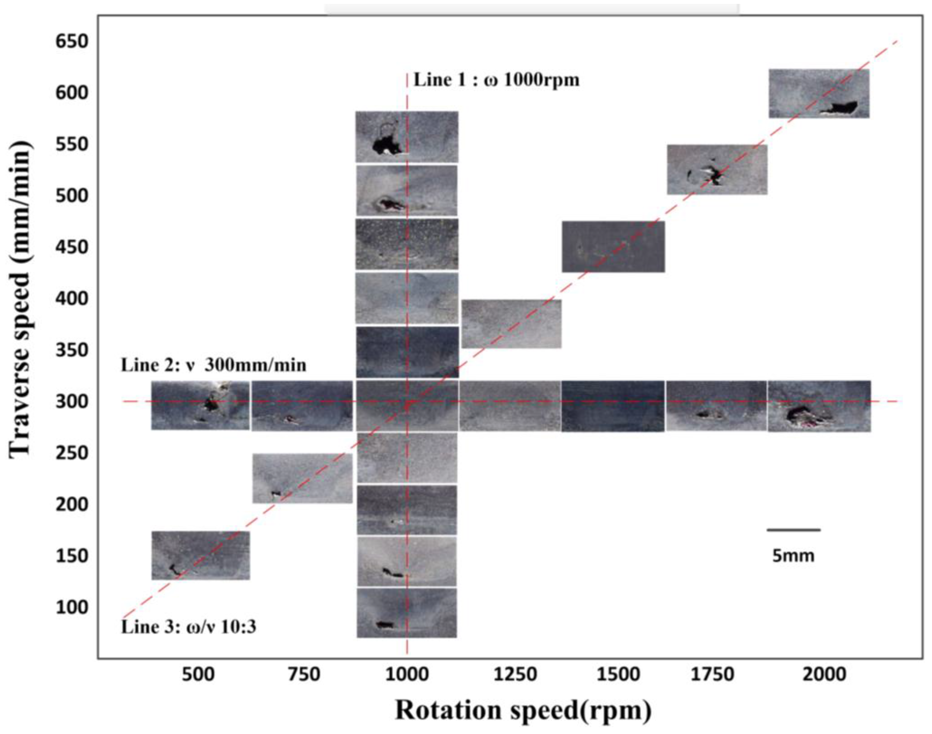
3.1. Single-Track Friction Stir Lap Welding

3.1.1. Single-Track FSLW with One-Pass Processing

Figure 4 shows the macrostructures of the stirred zone cross sections of one-pass FSLW components under diverse process parameters. It is clear from the macrographs that obvious defects are observed in the samples at most process parameters. Actually, FSLW was developed based on the principle of FSW, and FSW has been widely found to have the characteristic of narrow parameter range [16,17,18,19,20]. For the current case, it is more difficult to produce high-quality welds by FLSW compared with the widely studied friction stir butt welding. It makes the FSLW more highly dependent on the welding parameters [21].
The formation of defects is sensitive to the heat input, which mainly depends on the rotational speed (ω), traverse speed (ν) and plunge depth (h). According to the experimental results, the effect of the plunge depth on the defect formation is relatively slight, but the increase of the plunge depth largely raises the load of machine tool. Therefore, the plunge depth is fixed at 0.2 mm, and the effect of the change of rotational speed and traverse speed on fabrication quality is mainly investigated. The Line 1 in Figure 4 shows the results corresponding to a constant rotational speed of 1000 rpm (this parameter was optimized after lots of trial and error). At high traverse speeds, there were apparent holes near the bottom of the nugget. This results from the insufficient material fluidity, caused by the deficiency of heat input. The hole size is found to significantly decrease when the traverse speed reduces to 300 mm/min, owing to the augment of heat input. As the traverse speed continues to decrease, apparent defects appear again, due to the abnormal stirring. Sometimes, the material is even melted induced by the excess heat input [22]. Therefore, the traverse speed is fixed to 300 mm/min, and the rotation speed is changed, as indicated by the Line 2 of Figure 4. It can be seen that some serious defects, such as groove-type defect, appear at low rotational speed (lower than 500 rpm) because of the serious shortage of heat input. Meanwhile, the hole size decreases as the rotational speed grows up to 1000 rpm. At the rotational speed between 1000 rpm and 1500 rpm, the hole is not discernible but could be observed under the microscope. After the rotational speed increases to larger than 1500 rpm, the apparent hole appears again. Therefore, the processing parameters are chosen as ν 300 mm/min and ω 1000 rpm.
As maintained by related FSW studies [23,24], ω/ν is an important parameter to characterize heat input for 2024 aluminum alloy fabricated by FSW. According to the experimental results above, a relatively suitable heat input is obtained at a ω/ν ratio of 10:3. Therefore, good molding quality is expected, if rotational speeds and traverse speeds are varied but their ratio ω/ν keeps 10:3. However, as indicated along the Line 3 in Figure 4, apparent holes are still found for many cases. The best possible result was still obtained under ν 300 mm/min and ω 1000 rpm. The forming process of FSLW technology is complicated, which involves complex material flow and thermal cycling. The above results suggest that it is hard to find a specific parameter (such as ω/ν) to characterize the molding quality in FSLW.

3.1.2. Single-Track FSLW with Two-Pass Processing

Figure 5 shows the macrostructures of the cross-sections, as well as the higher magnification image, for FSLW fabricated samples under diverse process parameters. Figure 5a clearly shows that some hole defects are obviously observed at the inappropriate parameter of ν 300 mm/min and ω 1250 rpm. With the appropriate parameter of ν 300 mm/min and ω 1000 rpm, the hole defects disappear, but kiss bonding defects are still present, as shown in Figure 5b. The kiss bonding defect is very common in FSW, and it mainly results from the complicated material flow and insufficient pressure during FSLW. Furthermore, the interface of the plates is vertical to the tool, which makes it more difficult to sufficiently pulverize the oxide layers at the interfaces. In considerable repeated experiments, it is common to observe different degrees of kiss bonding defects with the optical microscope. Some special attempts were also taken in order to increase the material flow and pressure, such as slotted stirring pin, increasing tooth pitch and depth, using special shoulder surface. However, it is still difficult to realize non-defect forming. The main cause of kiss bonding defects in this study is abandoning the use of tilt angle, which is an important parameter for controlling defects [25,26,27].
The functional principle of the tilt angle is shown in Figure 6. During FSLW, the formation of the stir zone is attributed to the following processes. Firstly, the stirred materials become plastic under the action of compression and frictional heat. Secondly, the plastic regions of the lower plates move upwards and combine with the upper plate. Then, the combined materials move downwards along the left-hand thread pin. Finally, the combined materials are released from the pin owing to the motion of the tool, and the stir zone forms under the pressure provided by the shoulder [10]. On one hand, the existence of tilt angle increases the degree and scope of material flow, especially for the axial flow [28]. On the other hand, the sloping shoulder can provide not only the wrapped force F1 owing to the concave surface of the tool, but also an extra thrust force F2 due to the extrusion between the incline and the plastic material as shown in Figure 6a. Therefore, the material flow and the force in the FSLW process without tilt angle are less than that with tilt angle to a certain extent as shown in Figure 6b. The axial material flow in the process without tilt angle is provided only by the left-hand thread pin. It is not enough to crush the oxide layers of the plates and completely fill up the original gap between the plates. Therefore, the coarse alumina particles and kiss bonding defects are left.
The coarse alumina particles and kiss bonding defects will seriously affect the performance of the components, which must be avoided by using some special methods. In this study, the method of two-pass processing was taken in this study to eliminate the kiss bonding defects and refine the oxide particles, which is also used in friction stir processing by a few researchers [29,30]. The schematic illustration of two-pass processing during FSLW is shown in Figure 7. Some coarse alumina particles and various degrees of kiss bonding defects are left after the first pass processing due to the above-mentioned factors as shown in Figure 7a. Then the second pass processing with the same technological parameters was conducted. The aim of this processing was not deleting the whole oxide layers and original gap between the plates, but destructing the coarse alumina particles and kiss bonding defects. Accordingly, the material flow and the pressure provided by the second pass processing are sufficient to eliminate the kiss bonding defects and refine the oxide particles as shown in Figure 7b. This idea is also verified by our experiments. According to the microstructure shown in Figure 5c, defect-free component is obtained after two-pass processing.

3.2. Multi-Track Friction Stir Lap Welding

The existing investigations about the microstructure and mechanical properties of FSLW fabricated samples mainly focus on the single-track multilayer processing; studies on multi-track processing are relatively scarce. In this study, multi-track FSLW processing of 2024-O aluminum alloy is investigated. The theoretical width of the stirred zone after single-track FSLW should be eight millimeters, because the pin diameter used in the processing is eight millimeters, but a distinct unbonded defect is found between the adjacent tracks in multi-track FSLW under a hatch distance of eight millimeters (offset between two neighboring tracks), as shown in Figure 8a. The hook is a kind of inherent feature in friction stir lap welding process [31], which is characterized by a crack-like unbonded defect on both the advancing side and retreating side of the deformed faying surfaces. Accordingly, the actual effective width of the stirred zone after single-track FSLW is smaller than the pin diameter owing to the hook. The unbonded defects between the adjacent tracks are significantly diminished under a 7.2 mm hatch distance (10% overlapping rate), as shown in Figure 8b. When it reached 6.4 mm (20% overlapping rate), the unbonded defects disappeared and a component with dense microstructure was formed, as shown in Figure 8c.

3.3. Microstructure and Mechanical Properties

These components with full density were analyzed for the characterization of microstructure, mechanical properties and fracture surface. To show the influence of FSLW processing on the microstructure, the components of the FSLW fabricated sample and rolled substrate are cross-sectioned to observe the microstructure by optical microscope, as shown in Figure 9a,b, respectively. The original microstructure of the rolled substrate is characterized by coarse banded grains (see Figure 9b), and the FSLW fabricated sample is characterized by a typical feature with ultrafine equiaxed grains (see Figure 9a). The micrographs show that the average grain size reduced from about 150 μm to 9.4 μm after processing owing to dynamic recrystallization. Moreover, the microstructure evolution is a very complex process described as follows: (1) Firstly, the parent grains split into coarse band structures; (2) Secondly, some new elongated fibrous grains are formed owing to the increasing of the strain, and then further grain subdivision occurs continuously; (3) Then, fine nugget scale grains are formed with the increasing of temperature. The bands of fine grains are forced together and increase in volume fraction with strain; (4) Finally, the unstable fibrous grain fragments form a full nugget-like microstructure consisting of low aspect ratio ultrafine grains [10].
Then, the mechanical properties of the FSLW sample and rolled substrate are measured by tensile test. Figure 10 gives the results of the yield strength, ultimate tensile strength, and the elongation rate of the tensile tests. Compared with the rolled substrate, all three mechanical properties of FSLW samples increase observably. The FSLW tensile specimens shows an average yield stress of about 117.2 MPa and a tensile stress of about 227.8 MPa, which are about 17.55% and 6.45% higher than those of rolled substrate, respectively. In particular, the elongation rate increases from 14.52% of the rolled substrate to about 31.05% of FSLW samples, which is about two times that of rolled substrate.
The simultaneous increase in strength and ductility after FSLW can be attributed to the radical changes in the microstructure. Many researchers have studied the relationship between mechanical properties and microstructure. The mechanical property of the alloy is directly affected by the average grain size, according to the Hall-Petch equation [32]. Therefore, the formation of finer grains of the samples contributes to higher tensile strength and coarser grains easily lead to poor tensile properties. During the FSLW process, the severe plastic deformation and dynamic recrystallization lead to the ultrafine equiaxed grains that result in the significant improvement of mechanical properties. Furthermore, the fracture surface morphologies of the tensile specimens are characterized by SEM. In comparison with the fracture surface of the substrate sample (see Figure 11b), the FSLW fabricated samples have deeper and finer dimples (see Figure 11a), consistent with their higher ductility. In addition, it should be noted that the strength of all the samples is not very high, because the 2024-O alloy substrate has a lack of precipitation strengthening [33].

4. Conclusions

In this study, a full density multi-track 2024-O aluminum alloy component was successfully manufactured by FSLW without the application of tool tilt angle. The corresponding processing, defects, microstructures and tensile properties were investigated. According to the experimental results and theoretical analysis, the main conclusions are summarized as follows:
(1)
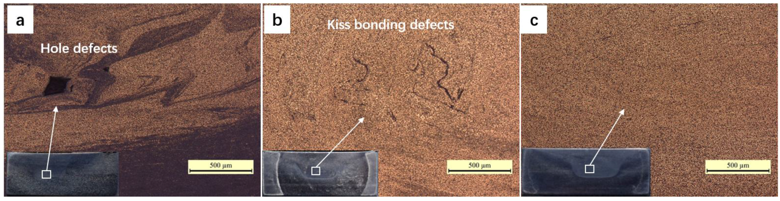
Defects generated during FSLW are very sensitive to the variation of parameters. Systematic studies were carried out to determine the suitable processing parameters. The rotational speed and traverse speed are found to play an important role in hole generation.
(2)
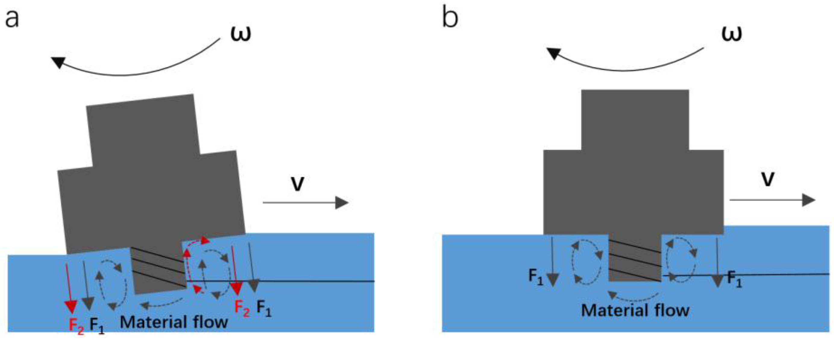
Tilt angle has a certain positive effect on defect elimination, but significantly increases equipment cost. Alternatively, two-pass processing is found to be able to replace the tilt angle and ensure defect-free forming. Under two-pass processing with welding speed 300 mm/min, rotation rate 1000 rpm and plunge depth 0.2 mm, defect-free samples were successfully fabricated.
(3)
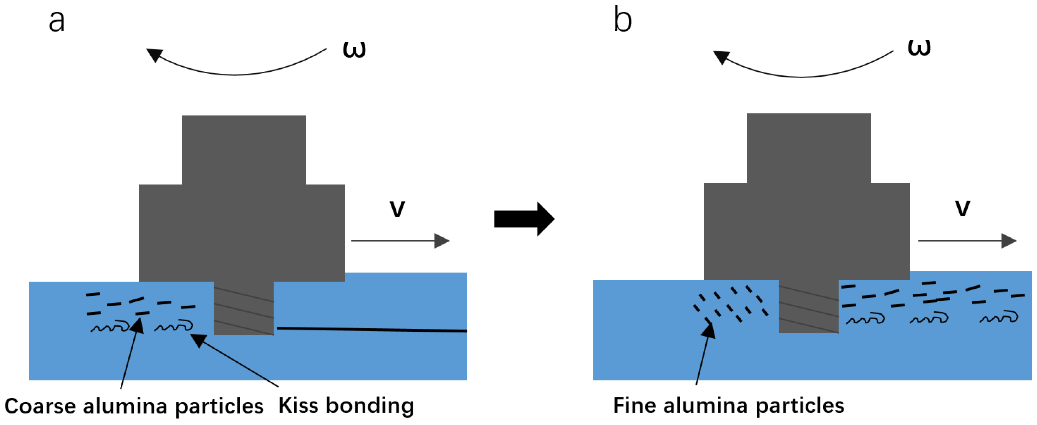
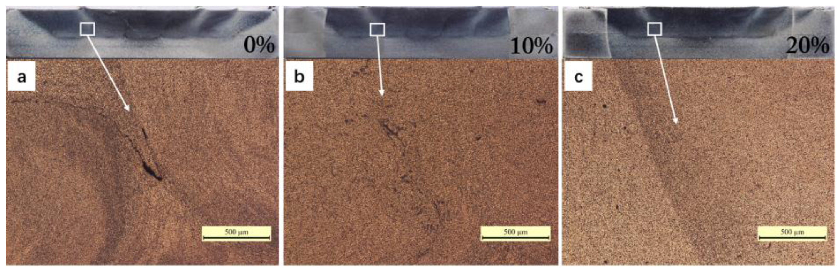
Hook-shaped defects are an inherent feature of FSLW, which combine to become crack-like unbonded defects in the overlapping zone during multi-track processing. The overlapping rate of 20% is found to be enough to eliminate these unbonded defects, and obtain full density multi-track samples.
(4)
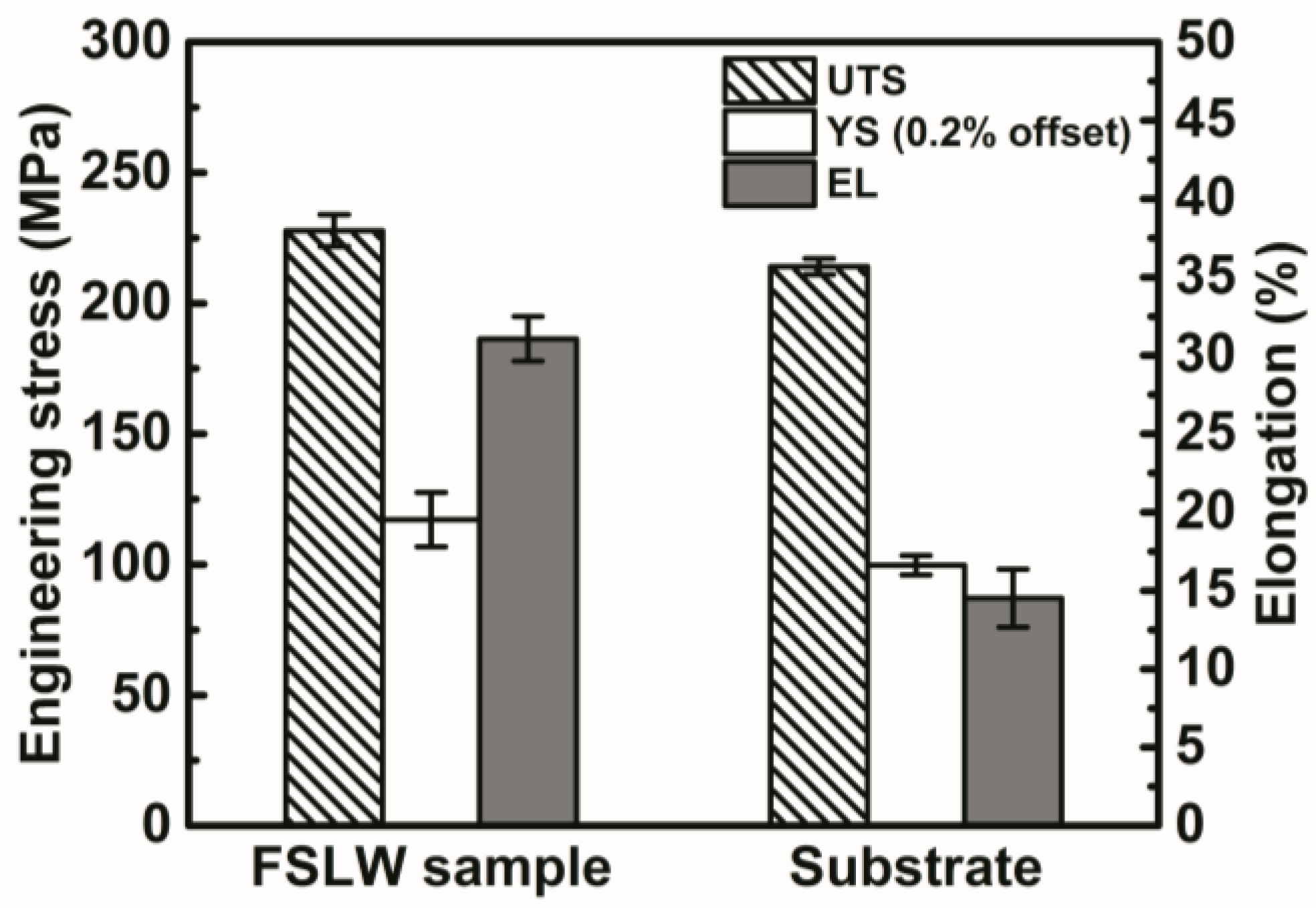
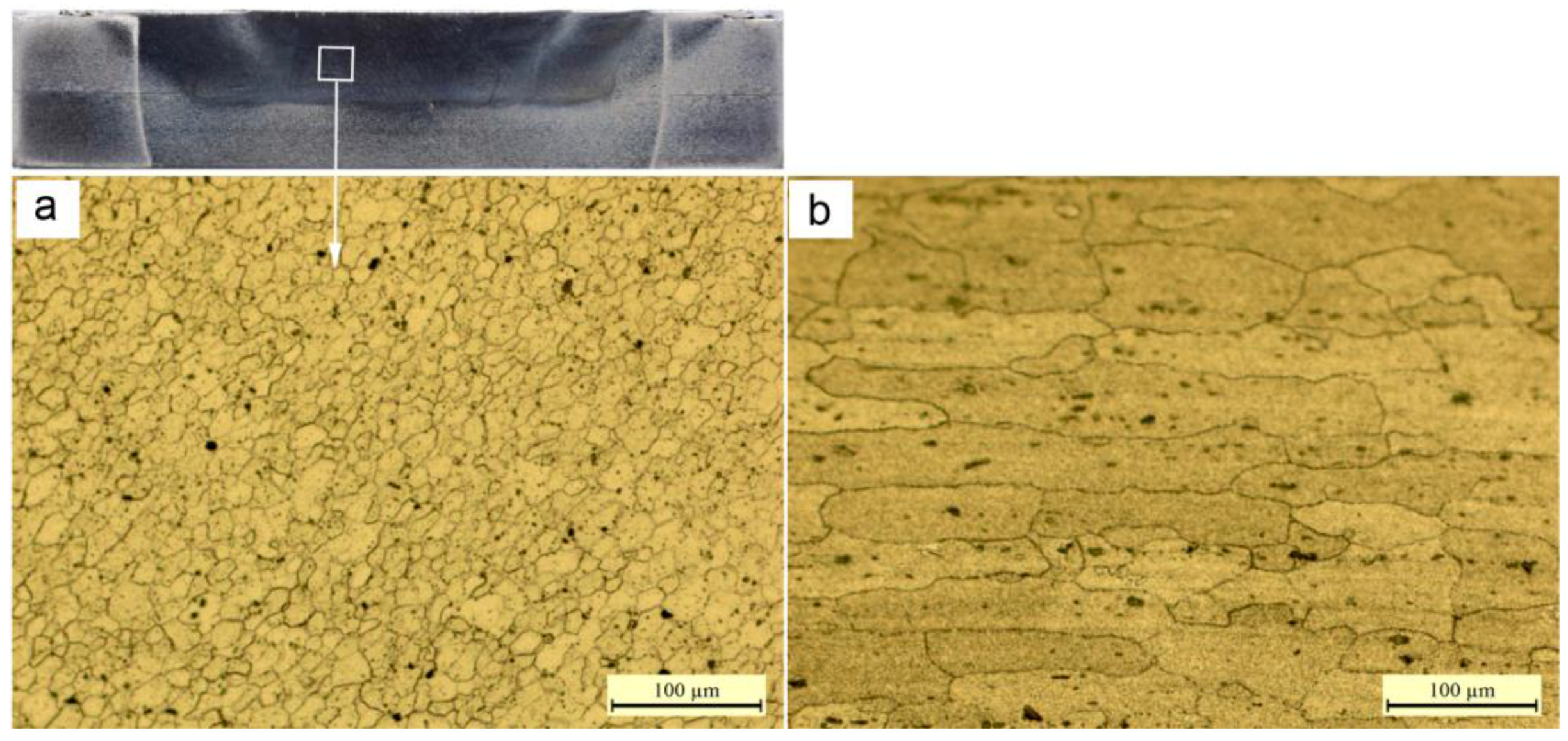
Ultrafine equiaxed grains with the diameter about 9.4 μm are obtained in FSLW samples, because of the dynamic recrystallization during FSLW. Accordingly, the strength of the multi-track FSLW samples is much higher than that of the rolled 2024-O substrate. Meanwhile, it exhibits a high ductility of the elongation about 31.05%, which is about two times that of the rolled 2024-O substrate.

Acknowledgments

The work was financially supported by the National Natural Science Foundation of China (51505033), Beijing Natural Science Foundation (3162027), and Excellent Young Scholars Research Fund of Beijing Institute of Technology (2015YG0302).

Author Contributions

Shengke Zou performed most of experiments and wrote this manuscript. Changmeng Liu designed the research, helped analyze the experimental data and gave some constructive suggestions. Limin Ma and Jing Guo helped do some experiments. Shuyuan Ma, Cheng Chen and Jiping Lu participated in the discussion on the results and guided the writing of the article.

Conflicts of Interest

The authors declare no conflict of interest.

References

  1. Hu, Z.; Yuan, S.; Wang, X.; Liu, G.; Huang, Y. Effect of post-weld heat treatment on the microstructure and plastic deformation behavior of friction stir welded 2024. Mater. Des. 2011, 32, 5055–5060. [Google Scholar] [CrossRef]
  2. Brandl, E.; Heckenberger, U.; Holzinger, V.; Buchbinder, D. Additive manufactured AlSi10Mg samples using selective laser melting (SLM): Microstructure, high cycle fatigue, and fracture behavior. Mater. Des. 2012, 34, 159–169. [Google Scholar] [CrossRef]
  3. Kwon, J.W.; Kang, M.S.; Yoon, S.O.; Kwon, Y.J.; Hong, S.T.; Kim, D.I.; Lee, K.H.; Seo, J.D.; Moon, J.S.; Han, K.S. Influence of tool plunge depth and welding distance on friction stir lap welding of AA5454-O aluminum alloy plates with different thicknesses. Trans. Nonferrous Met. Soc. Chin. 2012, 22, 624–628. [Google Scholar] [CrossRef]
  4. Mishra, R.S.; Ma, Z.Y. Friction stir welding and processing. Mater. Sci. Eng. R Rep. 2005, 50, 13–58. [Google Scholar] [CrossRef]
  5. Celik, S.; Cakir, R. Effect of friction stir welding parameters on the mechanical and microstructure properties of the Al-Cu butt joint. Metals 2016, 6, 133. [Google Scholar] [CrossRef]
  6. Moreira, P.M.G.P.; Figueiredo, M.A.V.D.; Castro, P.M.S.T.D. Fatigue behaviour of fsw and mig weldments for two aluminium alloys. Theor. Appl. Fract. Mech. 2007, 48, 169–177. [Google Scholar] [CrossRef]
  7. Chen, Z.W.; Yazdanian, S. Friction stir lap welding: Material flow, joint structure and strength. J. Achieve Mater. Manuf. Eng. 2012, 55, 629–637. [Google Scholar]
  8. Zhang, H.; Wang, M.; Zhang, X.; Zhu, Z.; Yu, T.; Yang, G. Effect of welding speed on defect features and mechanical performance of friction stir lap welded 7b04 aluminum alloy. Metals 2016, 6, 87. [Google Scholar] [CrossRef]
  9. Ghosh, M.; Kumar, K.; Mishra, R.S. Friction stir lap welded advanced high strength steels: Microstructure and mechanical properties. Mater. Sci. Eng. A 2011, 528, 8111–8119. [Google Scholar] [CrossRef]
  10. Mao, Y.; Ke, L.; Huang, C.; Liu, F.; Liu, Q. Formation characteristic, microstructure, and mechanical performances of aluminum-based components by friction stir additive manufacturing. Int. J. Adv. Manuf. Technol. 2015, 83, 1637–1647. [Google Scholar]
  11. Palanivel, S.; Sidhar, H.; Mishra, R.S. Friction stir additive manufacturing: Route to high structural performance. JOM 2015, 67, 616–621. [Google Scholar] [CrossRef]
  12. Palanivel, S.; Nelaturu, P.; Glass, B.; Mishra, R.S. Friction stir additive manufacturing for high structural performance through microstructural control in an mg based WE43 alloy. Mater. Des. 2015, 65, 934–952. [Google Scholar] [CrossRef]
  13. Hamid, H.A.D.; Roslee, A.A. Study the role of friction stir welding tilt angle on microstructure and hardness. Appl. Mech. Mater. 2015, 799–800, 51–60. [Google Scholar] [CrossRef]
  14. Badheka, V.J. Effects of tilt angle on properties of dissimilar friction stir welding copper to aluminum. Adv. Mater. Manuf. Process. 2016, 31, 255–263. [Google Scholar]
  15. Latif, A.; Fadhil, M. Friction Stir Welding (FSW): The Effect of Tilting Angle; Universiti Teknologi Petronas: Seri lskandar, Malaysia, 2013. [Google Scholar]
  16. Luo, C.; Li, X.; Song, D.; Zhou, N.; Li, Y.; Qi, W. Microstructure evolution and mechanical properties of friction stir welded dissimilar joints of Mg–Zn–Gd and Mg–Al–Zn alloys. Mater. Sci. Eng. A 2016, 664, 103–113. [Google Scholar] [CrossRef]
  17. Salari, E.; Jahazi, M.; Khodabandeh, A.; Ghasemi-Nanesa, H. Influence of tool geometry and rotational speed on mechanical properties and defect formation in friction stir lap welded 5456 aluminum alloy sheets. Mater. Des. 2014, 58, 381–389. [Google Scholar] [CrossRef]
  18. Song, Y.; Yang, X.; Cui, L.; Hou, X.; Shen, Z.; Xu, Y. Defect features and mechanical properties of friction stir lap welded dissimilar AA2024–AA7075 aluminum alloy sheets. Mater. Des. 2014, 55, 9–18. [Google Scholar] [CrossRef]
  19. Arbegast, W.J. A flow-partitioned deformation zone model for defect formation during friction stir welding. Scr. Mater. 2008, 58, 372–376. [Google Scholar] [CrossRef]
  20. Colligan, K.J.; Mishra, R.S. A conceptual model for the process variables related to heat generation in friction stir welding of aluminum. Scr. Mater. 2008, 58, 327–331. [Google Scholar] [CrossRef]
  21. Soundararajan, V.; Yarrapareddy, E.; Kovacevic, R. Investigation of the friction stir lap welding of aluminum alloys AA 5182 and AA 6022. J. Mater. Eng. Perform. 2007, 37, 74–76. [Google Scholar] [CrossRef]
  22. Kim, Y.G.; Fujii, H.; Tsumura, T.; Komazaki, T.; Nakata, K. Three defect types in friction stir welding of aluminum die casting alloy. Mater. Sci. Eng. A 2006, 415, 250–254. [Google Scholar] [CrossRef]
  23. Ren, S.R.; Ma, Z.Y.; Chen, L.Q. Effect of welding parameters on tensile properties and fracture behavior of friction stir welded Al–Mg–Si alloy. Scr. Mater. 2007, 56, 69–72. [Google Scholar] [CrossRef]
  24. Radisavljevic, I.; Zivkovic, A.; Radovic, N.; Grabulov, V. Influence of FSW parameters on formation quality and mechanical properties of Al 2024-T351 butt welded joints. Trans. Nonferrous Met. Soc. Chin. 2013, 23, 3525–3539. [Google Scholar] [CrossRef]
  25. Reddy, P.J.; Kailas, S.V.; Srivatsan, T.S. Effect of tool angle on friction stir welding of aluminum alloy 5052: Role of sheet thickness. Adv. Mater. Res. 2011, 410, 196–205. [Google Scholar] [CrossRef]
  26. Bilgin, M.B.; Meran, C.; Canyurt, O.E. Effect of tool angle on friction stir weldability of AISI 430. Weld. J. 2013, 92, 42–46. [Google Scholar]
  27. Behmand, S.A.; Mirsalehi, S.E.; Omidvar, H.; Safarkhanian, M.A. Single- and double-pass fsw lap joining of AA5456 sheets with different thicknesses. Mater. Sci. Technol. 2016. [Google Scholar] [CrossRef]
  28. Mishra, R.S.; Mahoney, M.W. Friction Stir Welding and Processing II; Springer: Berlin, Germany, 2014; pp. 13–58. [Google Scholar]
  29. El-Rayes, M.M.; El-Danaf, E.A. The influence of multi-pass friction stir processing on the microstructural and mechanical properties of aluminum alloy 6082. J. Mater. Process. Technol. 2012, 212, 1157–1168. [Google Scholar] [CrossRef]
  30. Aktarer, S.M.; Sekban, D.M.; Saray, O.; Kucukomeroglu, T.; Ma, Z.Y.; Purcek, G. Effect of two-pass friction stir processing on the microstructure and mechanical properties of as-cast binary Al–12Si alloy. Mater. Sci. Eng. A 2015, 636, 311–319. [Google Scholar] [CrossRef]
  31. Aldanondo, E.; Arruti, E.; Alvarez, P.; Echeverria, A. Mechanical and Microstructural Properties of Fsw Lap Joints; Springer International Publishing: Berlin, Germany, 2013; pp. 35–43. [Google Scholar]
  32. Zhu, Y.Z.; Wang, S.Z.; Li, B.L.; Yin, Z.M.; Wan, Q.; Liu, P. Grain growth and microstructure evolution based mechanical property predicted by a modified hall–petch equation in hot worked Ni76Cr19AlTiCo alloy. Mater. Des. 2014, 55, 456–462. [Google Scholar] [CrossRef]
  33. Ramesh, K.N.; Pradeep, S.; Pancholi, V. Multipass friction-stir processing and its effect on mechanical properties of aluminum alloy 5086. Metall. Mater. Trans. A 2012, 43, 4311–4319. [Google Scholar] [CrossRef]
Figure 1. Schematic of the multi-track friction stir lap welding (FSLW) process.
Metals 07 00001 g001
Figure 2. Schematic diagram of (a) clamping; (b) tool and (c) experimental procedure.
Metals 07 00001 g002
Figure 3. Sample preparation: (a) cross sections for microstructure observations; (b) manufacturing procedure of tensile specimens and (c) dimensions of tensile specimens.
Metals 07 00001 g003
Figure 4. The stirred zone cross sections of one-pass FSLW components under diverse process parameters.
Metals 07 00001 g004
Figure 5. Local magnifications of nugget at diverse process parameters: (a) ν 300 mm/min and ω 1250 rpm with one-pass processing; (b) ν 300 mm/min and ω 1000 rpm with one-pass processing; (c) ν 300 mm/min and ω 1000 rpm with two-pass processing.
Metals 07 00001 g005
Figure 6. Schematic of metal flow and molding pressure: (a) FSLW process with tilt angle and (b) FSLW process without tilt angle.
Metals 07 00001 g006
Figure 7. Schematic of two-pass processing for defect elimination: (a) first processing and (b) second processing.
Metals 07 00001 g007
Figure 8. Local magnifications of overlap regions at different overlapping rates in multi-track samples: (a) 0%; (b) 10%; and (c) 20%.
Metals 07 00001 g008
Figure 9. Optical microscope images showing the microstructures of (a) FSLW 2024 sample; (b) rolled 2024-O substrate.
Metals 07 00001 g009
Figure 10. Tensile properties of FSLW samples and rolled 2024-O substrate.
Metals 07 00001 g010
Figure 11. Scanning electron microscopy (SEM) images showing the tensile fracture surface of (a) FSLW samples and (b) rolled substrate.
Metals 07 00001 g011
Table 1. Experimental parameters used to get appropriate parameters.
ParametersNo.Welding Speed, ν (mm/min)Rotation Speed, ω (rpm)Plunge Depth, h (mm)
Constant νa13005000.2
a23007500.2
a330010000.2
a430012500.2
a530015000.2
a630017500.2
a730020000.2
Constant ωb110010000.2
b215010000.2
b320010000.2
b425010000.2
b530010000.3
b635010000.2
b740010000.2
b845010000.2
b950010000.2
b1055010000.2
Constant ω/νc11505000.2
c22257500.2
c330010000.4
c437512500.2
c545015000.2
c652517500.2
c760020000.2
Table 2. FSLW parameters used in this study.
FSLW ParametersValues
Rotation speed1000 rpm
Traverse speed300 mm/min
Plunge depth0.2 mm
Tilt angle0
Overlapping rate20%
Tool path patternSame direction
Special processTwo-pass processing

