Article

Effect of Heavy Ion Irradiation Dosage on the Hardness of SA508-IV Reactor Pressure Vessel Steel

1
School of Materials Science and Engineering, Beihang University, Beijing 100191, China
2
Department of Materials Science and Engineering, The University of Tennessee, Knoxville, TN 37996, USA
3
Beijing Key Laboratory of Advanced Nuclear Materials and Physics, Beihang University, Beijing 100191, China
4
Department of Nuclear Engineering, Texas A&M University, College Station, TX 77843, USA
*
Authors to whom correspondence should be addressed.
Metals 2017, 7(1), 25; https://doi.org/10.3390/met7010025
Submission received: 6 November 2016 / Revised: 21 December 2016 / Accepted: 10 January 2017 / Published: 14 January 2017
(This article belongs to the Special Issue Radiation Effects in Metals)

Abstract

:
Specimens of the SA508-IV reactor pressure vessel (RPV) steel, containing 3.26 wt. % Ni and just 0.041 wt. % Cu, were irradiated at 290 °C to different displacement per atom (dpa) with 3.5 MeV Fe ions (Fe2+). Microstructure observation and nano-indentation hardness measurements were carried out. The Continuous Stiffness Measurement (CSM) of nano-indentation was used to obtain the indentation depth profile of nano-hardness. The curves showed a maximum nano-hardness and a plateau damage near the surface of the irradiated samples, attributed to different hardening mechanisms. The Nix-Gao model was employed to analyze the nano-indentation test results. It was found that the curves of nano-hardness versus the reciprocal of indentation depth are bilinear. The nano-hardness value corresponding to the inflection point of the bilinear curve may be used as a parameter to describe the ion irradiation effect. The obvious entanglement of the dislocations was observed in the 30 dpa sample. The maximum nano-hardness values show a good linear relationship with the square root of the dpa.

Graphical Abstract

1. Introduction

With the increasing demands for high capacity and long design life of nuclear reactors, the performance of existing reactor pressure vessel (RPV) steels is becoming less adequate. It is important that new RPV steels should possess higher yield strength and fracture toughness, lower ductile to brittle transition temperature, and excellent neutron irradiation embrittlement resistance. The SA508-IV RPV steel studied in this work is a new generation RPV steel, with higher nickel content and lower copper content, compared with SA508-III. Ni is well known for improving the low-temperature cleavage toughness by decreasing the energy barrier of kink formation [1,2]. To determine the performance of this steel under nuclear environments, it is necessary to investigate the effect of irradiation doses on the microstructure evolution and the mechanical properties of this new type of RPV steel. The microstructure of this SA508-IV steel is mainly martensite structure with retained austenite, which could guarantee strength and toughness.
Neutron irradiation embrittlement of RPV steels causes the most severe damage during operation of nuclear power stations. Due to the long-term damage production and the radioactivity of the neutron irradiation, the real neutron irradiation experiments are limited and very difficult to carry out. Instead, high-energy heavy ion irradiation has been extensively used to study the irradiation response of the candidate RPV steel because of the simplicity of use, easier control of irradiation parameters, reduction of cost, rapid damage production, and absence of induced radioactivity [3,4,5,6]. Ion irradiation is one of the best methods for investigation of irradiation embrittlement [7], and provides a rapid and flexible way to achieve high doses without the hazards induced by activation of the materials [8]. Furthermore, the displacement cascades induced by ion irradiation are similar to those induced by neutron irradiation [9]. On the other hand, the disadvantages of ion irradiation are inhomogeneous damage profiles and shallow irradiation depth compared to neutrons [10].
The purpose of this paper is to fully characterize the relationship between the measured nano-indentation test results and the irradiation doses. The classic Nix-Gao model was used to analyze the test results. Considering the limitation of ion-irradiation depth and sample size, the nano-indentation test is a quite useful method for the study of the mechanical properties of irradiated materials, which uses the recorded depth into the specimen of an indenter along with the applied load to determine the area of contact and obtain the hardness of the test specimen [11]. The technique Continuous Stiffness Measurement (CSM) offers a significant improvement in nano-indentation testing [12]. Compared with the loading-unloading method used in the past, the CSM has the great advantage of obtaining the depth profile with only a single indent. The irradiation hardening should be related to the irradiated microstructural features, which commonly belong to two groups: solute atom clusters and matrix damage [13].

2. Experimental Procedures

2.1. Testing Materials and Irradiation Conditions

The material used in this study is a new generation RPV steel SA508-IV, designed with high Ni (3.26 wt. %) and low Cu (0.041 wt. %) content. The detailed chemical compositions are shown in Table 1. The rolled steel underwent a heat treatment process of holding for 1.5 h at 920 °C, followed by water quenching (WQ) to room temperature (RT), re-heating to 650 °C for 30 h and then water cooling to RT, called the as-received state. Heavy ion irradiations were conducted with 3.5 MeV Fe ions (Fe2+) using the ion accelerator in the Texas A&M University (College Station, TX, USA) on these as-received state samples, at 290 ± 5 °C. The ion accelerator is shown in Figure 1. The Stopping and Ranges of Ions in Matters (SRIM) was used for the irradiation damage calculation. The irradiation damage (D, in dpa) could be calculated by the equation [14],
D = F N d 1 ion M mol ρ d N A
in which, F is the ion fluence, in ion/cm2; Mmol is the target’s molar mass, in g/mol; NA is the Avogadro’s constant.
The displacement damage and ion distribution versus depth calculated by SRIM is shown in Figure 2. It can be seen that the peak damage depth sits at around 1000 nm below the ion irradiated surface. The ion distribution reaches the peak value at around 1200 nm depth.
The corresponding dose calculation was done in pure Fe with the displacement energy Ed = 40 eV. The dose and dose rate at a depth of 300 nm were used for damage parameters. The applied dose rate was fixed at 1.74 × 10⁻³ dpa/s at the peak or 0.7 × 10⁻³ dpa/s at the depth of 300 nm. The doses reached 1, 2, 3, 10, 20, 30 dpa, respectively. A 6 mm × 6 mm ion beam was used in order to ensure full coverage on the samples. The parameters of ion-irradiation are shown in Table 2.
From Table 2, it can be seen that 30 dpa of ion-irradiation needs 420 min. Although the 30 dpa dosage of neutron irradiation needs hundreds of years in the neutron reactor in service, this RPV steel SA508-IV is designed for the fourth-generation nuclear reactor where the neutron flux inside will be much higher, especially in the fast reactor, therefore, it is essential to study the performance of SA-508-IV RPV steel under high dosage.

2.2. Microstructure Observation

After ion-irradiation, the samples were cut from the sample center along the irradiation direction. Standard grinding and polishing was applied, followed by etching with 5 vol % nital. The microstructure of the etched samples was examined using the Quanta 200F Field Emission Environmental Scanning Electron Microscopy (FEESEM) (FEI, Hillsboro, OR, USA).
Thin foils for TEM observation were prepared perpendicular to the irradiated surface using the Zeiss Auriga Crossbeam focused ion beam (FIB) system (Zeiss, Jena, Germany). To remove defects appearing under Ga implantation at the FIB preparation, the specimens were polished by low-energy ion sputtering of Ar ions accelerated at 150 V using an ultralow-energy Ar ion beam sputtering system. After sufficiently thinning, the samples were observed using the F20 Field Emission Transmission Electron Microscopy (FE-TEM) (FEI, Hillsboro, OR, USA).

2.3. Nano-Indentation Tests

The nano-indentation hardness at room temperature was measured using a Nano Indenter XP (MTS, Eden Prairie, MN, USA) with a 2 μm diamond Berkovitch indenter (three-sided pyramid) under a maximum load of 500 mN. The Continuous Stiffness Measure (CSM) was used to study the mechanical properties. The depth (h) profiles of nano-hardness (H) up to a depth of about 2000 nm were obtained using this CSM method in the study. Five indentations were made on each of the specimens.

3. Results and Discussion

3.1. Microstructure

In the as-received state samples, the coarse carbides are mainly M23C6 types, which were observed in our previous work [15]. High density of fine M6C carbides formed after the ion irradiation, which were supposed to form in the high-nickel RPV steels after irradiation [16,17]. In our recent study, the Cu-rich clusters (CRCs) preferred to form under low dose irradiation (3 dpa) but disappeared after high dose (30 dpa), whereas Mo atoms started to segregate onto Cr/Mn precipitates to form Cr/Mn/Mo until irradiated at high dose (30 dpa) [18].
The microstructures of samples after different ion-irradiation doses, 3 dpa, 10 dpa, 20 dpa, and 30 dpa, are shown in Figure 3a–d, respectively, from which it can be seen that there are no significant differences between the martensitic microstructure of the four differently dosed ion-irradiated samples. Thus it could be speculated that ion irradiation affects the density or size of the nano-clusters/precipitates much more than grain size or phases structure.

3.2. Nano-Hardness

The indentation depth profiles of nano-hardness corresponding to different dpa are plotted in Figure 4 which demonstrates that the nano-hardness curves of the irradiated samples are related to the irradiation doses with the non-irradiated at the bottom and the 30 dpa irradiated at the top. It can be seen that the nano-hardness curve of each state sample can be divided into three regions. The nano-hardness value goes up with increase of depth initially, and reaches the highest value near the surface (region A), and then goes down with the further penetration into the samples (region B and C in Figure 4). The variation in region A is known as the reverse indentation size effect (RISE), whereas the phenomenon in the broader regions B and C (the decrease in hardness with further depth) is called the indentation size effect (ISE) [19,20].
In the region B, there are plateau damage profiles in the low dose irradiation samples (1–3 dpa). With the increase of the dosage, the plateau stage weakens (10 dpa), and then disappears (20 dpa), but shows up again in the 30 dpa sample. Considering the CRCs in the 3 dpa sample which disappear in the 30 dpa sample, demonstrated in our previous study [18], the formation of CRCs could be related to the appearance of the plateau stage (90–180 nm depth) in the nano-hardness curves of the low irradiation dose samples. The plateau damage profile represents the damage saturation. Therefore, it could be concluded that the hardening effect after low doses of ion irradiation is because of the formation of CRCs, and the nano-hardness profiles reach the plateau stage due to the saturation of CRCs. Furthermore, there is also an obvious plateau profile (110–230 nm depth region) in the 30 dpa sample. The hardening effect under higher dosage is probably caused by the formation of the interstitial-type dislocation loops and the Cr/Mn/Mo precipitates. The plateau stage of the 30 dpa curve can be considered to result from loop coalescence [21]. As for the depth of the plateau stage, it could be seen in Figure 4 that the plateau stage in the 30 dpa sample is deeper than that in the low dose samples. This could be explained as accumulation of irradiation defects and a move-forward towards the inner of the samples with increasing irradiation dose.
According to the Nix and Gao equation [22] for the ISE stage, which describes the relationship between nano-hardness (H) and depth (h),
H = H 0 ( 1 + ( l * h ) ) 0.5
where H is the hardness for a given depth of indentation h; H0 is the hardness at the limit of infinite depth; l* is a characteristic length that depends on the shape of the indenter, the shear modulus and H0.
The curves of the ISE stage (region B and C) in Figure 4 could be replotted in Figure 5. The circled area in Figure 5a is enlarged and shown in Figure 5b. There is a difference between the irradiated samples and the non-irradiated sample (0 dpa). The slope of the non-irradiated curve remains constant in the ISE stage, while the slopes of the irradiated ones change at the critical indentation depth, forming the bilinear curves. According to Equation (2), H02 × l* is equal to the slope of the curves in Figure 5. It could be found that there are not many differences between the H0irr and H0unirr, thus the ion irradiation affects l* dramatically. As stated in Equation (2), the l* depends on the shape of the indenter, the H0 and the shear modulus. The effect of ion irradiation is therefore mainly on the shear modulus of the materials. The C region in Figure 4 corresponds to the initial linear part of the curves in Figure 5, which is not significantly affected by the ion-irradiation. The following increased part of the irradiated curves in Figure 5 represents the region B (Figure 4), which is the area influenced mostly by the ion irradiation. The bilinear profile of the irradiated samples in Figure 5b is formed due to the soft substrate effect (SSE) of the deeper area just beneath the irradiated depth area [20,22].
From Equation (2) it could be found that the slope of the second line just after the inflection point of the bilinear curves in Figure 5b is equal to H02 × l*. Thus the l* of the irradiated stage could be obtained by the slope divided by H02 for each state sample. The relationship between l* and dpa is plotted in Figure 6. In Figure 6, it could be seen that the increase rate of l* is higher under low dosage than that under high dosage, which means the l* value becomes constant when the ion irradiation dose is high enough for the irradiation effect on the nano-hardness to reach the saturation state.
Figure 4 shows that each nano-hardness curve has a maximum value which varies with the irradiation doses. The relationship between the maximum nano-hardness and dpa is presented in Figure 7. The dose dependence of the maximum nano-hardness in Figure 7a is similar to that of the characteristic length l* as shown in Figure 6 which demonstrates a rapid increase at low doses and a slowdown of the rate of increase at higher doses, implying that the irradiation effect on nano-hardness would become saturated eventually after high dosage. Zhang et al. [3] proposed a power-law dependence of the nano-hardness on dpa. In this work, the maximum nano-hardness versus the square root of dpa in Figure 7b shows a linear increase relationship. The linear fitness result is,
H max = 12.26 + 2.09 dpa
where the constant 12.26 is the peak value of the nano-hardness curve for the non-irradiated sample, the coefficient 2.09 can be considered as the ion-irradiation hardening parameter, which could be used to evaluate the performance of the RPV steels under irradiation.
It can be seen in Figure 7 that the 3 dpa point remains higher up on the linear fitting line. Since the precipitates or clusters are formed in different stage of the Fe2+ ion irradiation process, the hardening mechanisms should also be different from low dose to high dose. The CRCs are known to form at low doses and to disappear at high doses [18,23,24,25], and Bohmert et al. have demonstrated that the increase in hardness has good correlation with the square root of the volume fraction of the solute atom clusters [26]. Thus, it could be speculated that the first hardening stage could be attributed to the formation of the CRCs. From the plateau damage profile of the 3 dpa in Figure 4 and the higher maximum nano-hardness point of 3 dpa in Figure 7, it can be concluded that the formation of CRCs becomes saturated when the dose of irradiation reaches 3 dpa. When the dose increases to 10 or 20 dpa, the hardening mechanism changes from the CRCs to the precipitates, such as the Cr/Mn/Mo, and different dislocation structures. The large scatter of 1 and 10 dpa data found from Figure 7b may be because of the variety of the microstructures or the surface condition.
The TEM observation results of the dislocations in the 3 dpa and 30 dpa samples are shown in Figure 8. It can be seen that the dislocations in the 3 dpa irradiated sample (Figure 8a) are mainly parallel and along the directions of ion irradiation. In contrast, in Figure 8b, the dislocations are found to be entangled with one other. Y. Takayama et al. [27] found that nickel element addition enhances the irradiation hardening of RPV steel during the irradiation process. Ni and Mn elements are reported to have the tendency to promote the formation of interstitial loops during irradiation [28,29,30] and the high dose of irradiation could generate high density of self-interstitial atoms by the cascade effect which results in the formation of interstitial-type dislocation loops [31,32]. Therefore, it can be considered that the entanglement of the dislocations and the interstitial-type dislocation loops are one of the main factors responsible for the hardening effect after high dose irradiation.
In Figure 4, it can be seen that there are multiple discontinuous displacement bursts occurring clearly in the nano-hardness versus depth curves of some ion-irradiated samples. Such a non-uniform displacement response named “pop-in” is marked by arrows in Figure 4 and Figure 5. The pop-ins on the 1 dpa curve occur around 25–50 nm depth, whereas the one on the 10 dpa curve stays around 85 nm depth. Generally, the occurrence of pop-in phenomenon in metals can be attributed to several factors such as dislocation nucleation and propagation, crack formation or phase transformation [33,34,35,36].
The pop-ins on nano-hardness curves of the SA508-IV steel samples in this study probably occurred due to the transformation of the retained austenite to martensite. During the measurement of the nano-hardness along the depth of the sample, the indenter may encounter the retained austenite. Because the retained austenite is relatively soft, the corresponding nano-hardness is lower which results in the drop of the nano-hardness on the curve. On the other hand, the plastic deformation of the retained austenite may induce transformation of the austenite to martensite which is much harder than the retained austenite. Thus the nano-hardness in the hardness-depth curve will increase, therefore, forming the pop-ins on the curves. Whether there are pop-ins on the curves depends on the distribution of the retained austenite. If there are retained austenite grains along the measuring depth of the sample, pop-ins would be generated, otherwise, there would be no pop-ins.
Attention should be paid to the inflection points of the bilinear curves (the crossing points of the two-line curves) in Figure 5b, corresponding to the cut-off point between B region and C region (Figure 4). The indentation depths at the inflection points are similar for the irradiated samples, but the nano-hardness value increases with the increase of the irradiation dosage. As mentioned above, the bilinear profile is attributed to the SSE of the non-irradiated area just beneath the irradiated area. Therefore, the nano-hardness value (Hinf) and the indentation depth (hirr/unirr) corresponding to the inflection point, can be considered as a parameter representing the irradiation mostly affected layer on the surface of the material, and below this layer, the effect of irradiation can be neglected.
The nano-hardness profiles in Figure 4 manifest when the measuring depth is over 1500 nm, the nano-hardness value remains almost constant. Therefore, to measure the nano-hardness as a property of a material, the indentation depth must be greater than 1500 nm. The nano-hardness value at a depth of ~2000 nm is taken as the material nano-hardness property in normal practice. To characterize the effect of ion irradiation on the nano-hardness of a material, however, different parameters should be applied since the effect of ion irradiation is limited within the surface thin layer of the material. As discussed above, the maximum nano-hardness value Hmax or the hardness value corresponding to the inflection point (Hinf) could be used to describe the irradiation effect on the nano-hardness of materials.

4. Conclusions

The heavy ion irradiation process was demonstrated to produce a similar cascade effect to neutron irradiation. Micro-mechanical properties were obtained by nano-hardness tests. Based on the above analysis, conclusions can be drawn as follows:
(1)
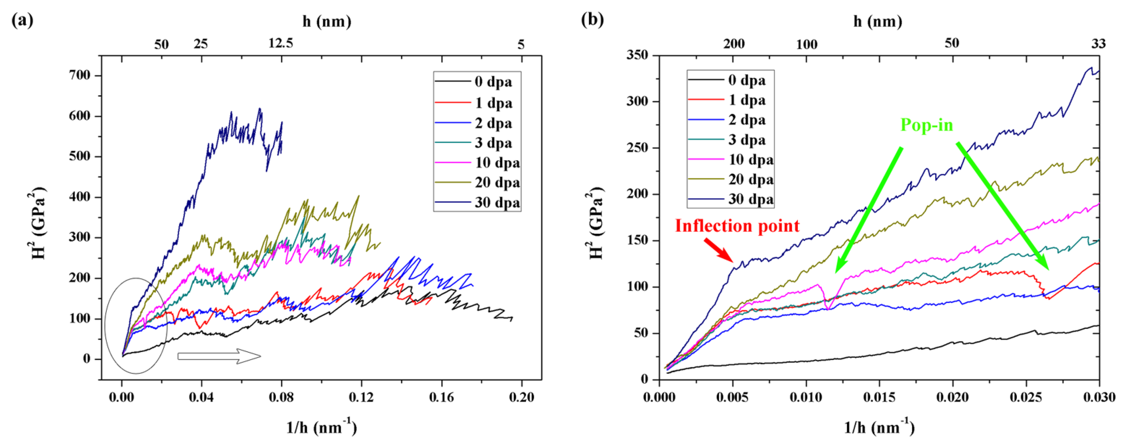
The CSM nano-hardness profiles of the irradiated SA508-IV steel samples exhibit a maximum value and a plateau.
(2)
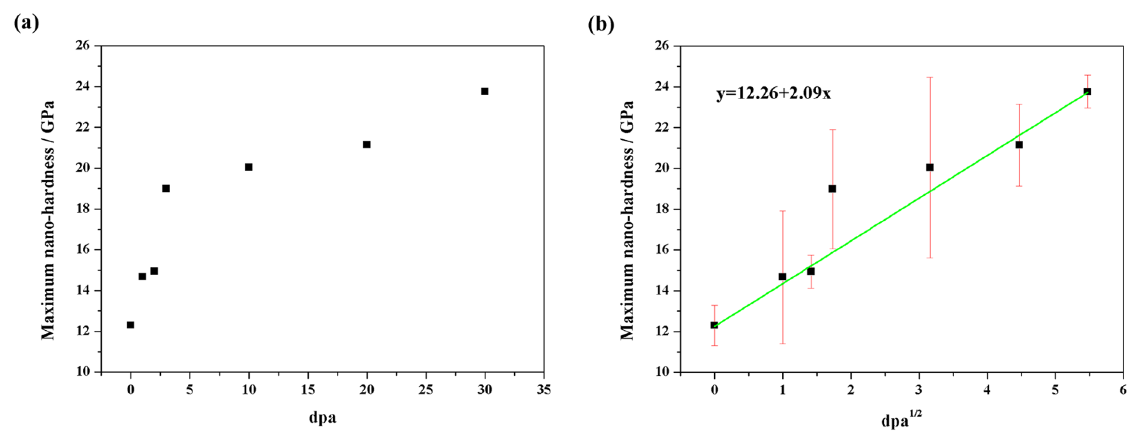
The maximum nano-hardness (Hmax) increases rapidly at low doses and slowly at higher doses. The relationship between Hmax and dpa follows a ½-power law.
(3)
The inflection point of the bilinear curve is the point separating the B region and C region on the CSM nano-hardness profile. Beyond the inflection point, the ion irradiation effect on the materials is insignificant.
(4)
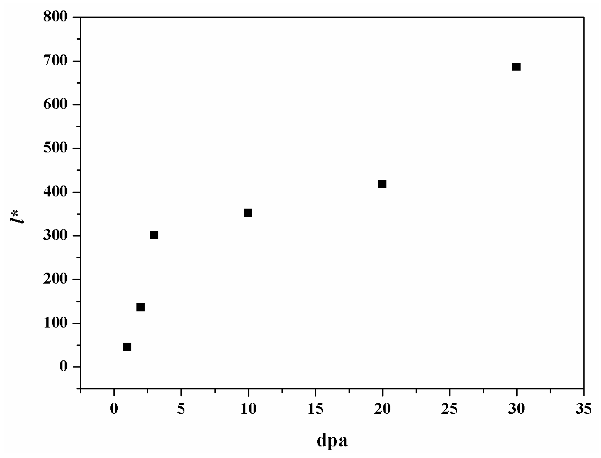
The characteristic length l* which is affected by ion-irradiation was obtained by fitting the bilinear curves, and also had a relationship with the displacement per atom (dpa).

Acknowledgments

This work is financially supported by the National Science and Technology Key Specific Project: Life Management Technology of Nuclear Power Plant of China (Grant No. 2011ZX06004-002). The authors would like to express thanks for the help with ion-irradiation experiments conducted in the Department of Nuclear Engineering in Texas A&M University (USA).

Author Contributions

Xue Bai designed the research, conducted the experiments, and then finished the draft of this paper, Sujun Wu and Peter K. Liaw supervised the project and help revised the manuscript, Lin Shao and Jonathan Gigax helped with the ion-irradiation experiments, all authors reviewed the manuscript.

Conflicts of Interest

The authors declare no conflicts of interest.

References

  1. Chen, Y.T.; Atteridge, D.G.; Gerberich, W.W. Plastic flow of Fe-binary alloys-I. A description at low temperatures. Acta Metall. 1981, 29, 1171–1185. [Google Scholar] [CrossRef]
  2. Gerberich, W.W.; Chen, Y.T.; Atteridge, D.G.; Johnson, T. Plastic flow of Fe-binary alloys-II. Application of the description to the ductile-brittle transition. Acta Metall. 1981, 29, 1187–1201. [Google Scholar] [CrossRef]
  3. Zhang, H.; Zhang, C.; Yang, Y.; Meng, Y.; Jang, J.; Kimura, A. Irradiation hardening of ODS ferritic steels under helium implantation and heavy-ion irradiation. J. Nucl. Mater. 2014, 455, 349–353. [Google Scholar] [CrossRef]
  4. Liu, P.P.; Bai, J.W.; Ke, D.; Wan, F.R.; Wang, Y.B.; Wang, Y.M.; Ohnuki, S.; Zhan, Q. Effects of deuterium implantation and subsequent electron irradiation on the microstructure of Fe-10Cr model alloy. J. Nucl. Mater. 2012, 423, 47–52. [Google Scholar] [CrossRef]
  5. Klueh, R.L.; Gelles, D.S.; Jitsukawa, S.; Kimura, A.; Odette, G.R.; van der Schaaf, B.; Victoria, M. Ferritic/martensitic steels-overview of recent results. J. Nucl. Mater. 2002, 307, 455–465. [Google Scholar] [CrossRef]
  6. Zhang, C.H.; Sun, Y.M.; Song, Y.; Shibayama, T.; Jin, Y.F.; Zhou, L.H. Defect production in silicon carbide irradiated with Ne and Xe ions with energy of 2.3 MeV/amu. Nucl. Instrum. Methods Phys. Res. B 2007, 256, 243–247. [Google Scholar] [CrossRef]
  7. Fujii, K.; Fukuya, K.; Hojo, T. Effects of dose rate change under irradiation on hardening and microstructural evolution in A533B steel. J. Nucl. Sci. Technol. 2013, 50, 160–168. [Google Scholar] [CrossRef]
  8. Zhang, Z.W.; Liu, C.T.; Wang, X.L.; Miller, M.K.; Ma, D.; Chen, G.; Williams, J.R.; Chin, B.A. Effects of proton irradiation on nanocluster precipitation in ferritic steel containing fcc alloying additions. Acta Mater. 2012, 60, 3034–3046. [Google Scholar] [CrossRef]
  9. Was, G.S.; Busby, J.T.; Allen, T.; Kenik, E.A.; Jenssen, A.; Bruemmer, S.M.; Gan, J.; Edwards, A.D.; Scott, P.M.; Andresen, P.L. Emulation of neutron irradiation effects with protons: Validation of principle. J. Nucl. Mater. 2002, 300, 198–216. [Google Scholar] [CrossRef]
  10. Liu, P.P.; Wan, F.R.; Zhan, Q. A model to evaluate the nano-indentation hardness of ion-irradiated materials. Nucl. Instrum. Methods Phys. Res. B 2015, 342, 13–18. [Google Scholar] [CrossRef]
  11. Fischer-Cripps, A.C. Nanoindentation Testing, Nanoindentation; Springer: Berlin, Germany, 2011. [Google Scholar]
  12. Li, X.D.; Bhushan, B. A review of nanoindentation continuous stiffness measurement technique and its applications. Mater. Charact. 2002, 48, 11–36. [Google Scholar] [CrossRef]
  13. Fujii, K.; Fukuya, K.; Hojo, T. Concomitant formation of different nature clusters and hardening in reactor pressure vessel steels irradiated by heavy ions. J. Nucl. Mater. 2013, 443, 378–385. [Google Scholar] [CrossRef]
  14. Hengstler-Eger, R.M.; Baldo, P.; Beck, L.; Dorner, J.; Ertl, K.; Hoffmann, P.B.; Hugenschmidt, C.; Kirk, M.A.; Petry, W.; Pikart, P.; et al. Heavy ion irradiation induced dislocation loops in AREVA’s M5 alloy. J. Nucl. Mater. 2012, 423, 170–182. [Google Scholar] [CrossRef]
  15. Bai, X.; Wu, S.; Liaw, P.K. Influence of thermo-mechanical embrittlement processing on microstructure and mechanical behavior of a pressure vessel steel. Mater. Des. 2016, 89, 759–769. [Google Scholar] [CrossRef]
  16. Klueh, R.L.; Hashimoto, N.; Sokolov, M.A.; Shiba, K.; Jitsukawa, S. Mechanical properties of neutron-irradiated nickel-containing martensitic steels: I. Experimental study. J. Nucl. Mater. 2006, 357, 156–168. [Google Scholar] [CrossRef]
  17. Klueh, R.L.; Hashimoto, N.; Sokalov, M.A.; Maziasz, P.J.; Shiba, K.; Jitsukawa, S. Mechianical properties of neutron-irradiated nickel-containing martensitic steels: II. Review and analysis of helium-effects studies. J. Nucl. Mater. 2006, 357, 169–182. [Google Scholar] [CrossRef]
  18. Bai, X.; Wu, S.; Liaw, P.K.; Shao, L.; Gigax, J.; Wei, L. Effect of ion irradiation on microstructure and nano-hardness of the SA508-IV reactor pressure vessel steel. Sci. Rep. submitted for publication. 2017. [Google Scholar]
  19. Pharr, G.M.; Herbert, E.G.; Gao, Y. The indentation size effect: A critical examination of experimental observations and mechanistic interpretations. Annu. Rev. Mater. Res. 2010, 40, 271–292. [Google Scholar] [CrossRef]
  20. Kasada, R.; Takayama, Y.; Yabuuci, K.; Kimura, A. A new approach to evaluate irradiation hardening of ion-irradiated ferritic alloys by nano-indentation techniques. Fusion Eng. Des. 2011, 86, 2658–2661. [Google Scholar] [CrossRef] [Green Version]
  21. Jiang, J.; Wu, Y.C.; Liu, X.B.; Wang, R.S.; Nagai, Y.; Inoue, K.; Shimizu, Y.; Toyama, T. Microstructural evolution of RPV steels under proton and ion irradiation studied by positron annihilation spectroscopy. J. Nucl. Mater. 2015, 458, 326–334. [Google Scholar] [CrossRef]
  22. Nix, W.D.; Gao, H. Indentation size effects in crystalline materials: A law for strain gradient plasticity. J. Mech. Phys. Solids 1998, 46, 411–425. [Google Scholar] [CrossRef]
  23. Yabuuchi, K.; Yano, H.; Kasada, R.; Kishimoto, H.; Kimura, A. Dose dependence of irradiation hardening of binary ferritic alloys irradiated with Fe3+ ions. J. Nucl. Mater. 2011, 417, 988–991. [Google Scholar] [CrossRef]
  24. Akamatsu, M.; van Duysen, J.C.; Pareige, P.; Auger, P. Experimental evidence of several contributions to the radiation damage in ferritic alloys. J. Nucl. Mater. 1995, 225, 192–195. [Google Scholar] [CrossRef]
  25. Tobita, T.; Suzuki, M.; Iwase, A.; Aizawa, K. Hardening of Fe-Cu alloys at elevated temperatures by electron and neutron irradiaions. J. Nucl. Mater. 2001, 299, 267–270. [Google Scholar] [CrossRef]
  26. Bohmert, J.; Viehrig, H.-W.; Ulbricht, A. Correlation between irradiation-induced changes of microstructural parameters and mechanical properties of RPV steels. J. Nucl. Mater. 2004, 334, 71–78. [Google Scholar] [CrossRef]
  27. Takayama, Y.; Kasada, R.; Sakamoto, Y.; Yabuuchi, K.; Kimura, A.; Ando, M.; Hamaguchi, D.; Tanigawa, H. Nanoindentation hardness and its extrapolation to bulk-equivalent hardness of F82H steels after single- and dual-ion beam irradiation. J. Nucl. Mater. 2013, 442, S23–S27. [Google Scholar] [CrossRef]
  28. Nishiyama, Y.; Onizawa, K.; Suzuki, M.; Anderegg, J.W.; Nagai, Y.; Toyama, T.; Hasegawa, M.; Kameda, J. Effects of neutron-irradiation-induced intergranular phosphorus segregation and hardening on embrittlement in reactor pressure vessel steels. Acta Mater. 2008, 56, 4510–4521. [Google Scholar] [CrossRef]
  29. Shibamoto, H.; Kitao, K.; Matsui, H.; Hasegawa, M.; Yamaguchi, S.; Kimura, A. Effects of Radiation on Materials, 20th International Symposium, ASTM STP 1405; Rosinski, S.T., Grossbeck, M.L., Allen, T.R., Kumar, A.S., Eds.; American Society for Testing and Materials: West Conshohocken, PA, USA, 2001; p. 722. [Google Scholar]
  30. Watanabe, H.; Arase, S.; Yamamoto, T.; Wells, P.; Onishi, T.; Odette, G.R. Hardening and microstructural evolution of A533b steels irradiated with Fe ions and electrons. J. Nucl. Mater. 2016, 471, 243–250. [Google Scholar] [CrossRef]
  31. Liu, P.P.; Zhao, M.Z.; Zhu, Y.M.; Bai, J.W.; Wan, F.R.; Zhan, Q. Effects of carbide precipitate on the mechanical properties and irradiation behavior of the low activation martensitic steel. J. Alloy. Compd. 2013, 579, 599–605. [Google Scholar] [CrossRef]
  32. Radiguet, B.; Pareige, P.; Barbu, A. Irradiation induced clustering in low copper or copper free ferritic model alloys. Nucl. Instrum. Methods Phys. Res. B 2009, 267, 1496–1499. [Google Scholar] [CrossRef]
  33. Qian, X.; Han, L.; Zhang, W.; Gu, J. Nano-indentation investigation on the mechanical stability of individual austenite in high-carbon steel. Mater. Charact. 2015, 110, 86–93. [Google Scholar]
  34. Kim, B.; Trang, T.T.T.; Kim, N.J. Deformation behavior of ferrite-austenite duplex high nitrogen steel. Met. Mater. Int. 2014, 20, 35–39. [Google Scholar] [CrossRef]
  35. Mistra, R.D.K.; Zhang, Z.; Jia, Z.; Venkat Surya, P.K.C.; Somani, M.C.; Karjalainen, L.P. Nanomechanical insights into the deformation behavior of austenitic alloys with different stacking fault energies and austenitic stability. Mater. Sci. Eng. A 2011, 528, 6958–6963. [Google Scholar] [CrossRef]
  36. Bahr, D.F.; Kramer, D.E.; Gerberich, W.W. Non-linear deformation mechanisms during nano-indentation. Acta Mater. 1998, 46, 3605–3617. [Google Scholar] [CrossRef]
Figure 1. The picture of the ion accelerator.
Metals 07 00025 g001
Figure 2. Depth profile of displacement per atom (dpa) and ion distribution in 3.5 MeV Fe2+ ion irradiation.
Metals 07 00025 g002
Figure 3. Microstructure of samples after different ion-irradiation doses, (a) 3 dpa; (b) 10 dpa; (c) 20 dpa; and (d) 30 dpa.
Metals 07 00025 g003
Figure 4. Depth profiles of nano-hardness of SA508-IV after different ion-irradiation doses.
Metals 07 00025 g004
Figure 5. H2 versus 1/h profile for the indentation size effect (ISE) region according to the Nix-Gao model, the circled area in (a) is enlarged in (b).
Metals 07 00025 g005
Figure 6. The relationship between the l* and dpa.
Metals 07 00025 g006
Figure 7. The relationship between the maximum nano-hardness and (a) dpa; (b) the square root of dpa.
Metals 07 00025 g007
Figure 8. Dislocation density of different dose ion-irradiation samples, (a) 3 dpa; (b) 30 dpa.
Metals 07 00025 g008
Table 1. Chemical composition of SA508-IV Ni-Cr-Mo alloy steel in wt. %.
CSiMnPSNiCrCuMoAlFe
0.150.360.340.0110.0083.261.660.0410.460.005Balance
Table 2. The parameters of ion-irradiation.
dpaFluenceDuration (min)
12.46 × 101514.01
24.92 × 101528.02
37.38 × 101542.03
102.46 × 1016140.1
204.92 × 1016280.2
307.38 × 1016420.3

