Article

Electropolishing Behaviour of 73 Brass in a 70 vol % H3PO4 Solution by Using a Rotating Cylinder Electrode (RCE)

1
Department of Mechanical Engineering, Chang Gung University, Taoyuan 33302, Taiwan
2
Department of Mechanical Engineering, Ming Chi University of Technology, New Taipei 24301, Taiwan
3
Bone and Joint Research Center, Chang Gung Memorial Hospital, Taoyuan 33305, Taiwan
*
Author to whom correspondence should be addressed.
Metals 2017, 7(1), 30; https://doi.org/10.3390/met7010030
Submission received: 19 August 2016 / Revised: 16 December 2016 / Accepted: 16 January 2017 / Published: 20 January 2017

Abstract

:
The electropolishing behaviour of 73 brass was studied by means of a rotating cylinder electrode (RCE) in a 70 vol % H3PO4 solution at 27 °C. Owing to the formation of a blue Cu2+-rich layer on the brass-RCE, an obvious transition peak was detected from kinetic- to diffusion-controlled dissolution in the anodic polarisation curve. Electropolishing was conducted at the potentials located at the transition peak, the start, the middle, and the end positions in the limiting-current plateau corresponding to the anodic polarisation curve of the brass-RCE. A well-polished surface can be obtained after potentiostatic electropolishing at the middle position in the limiting-current plateau. During potentiostatic etching in the limiting-current plateau, a blue Cu2+-rich layer was formed on the brass-RCE, reducing its anodic dissolution rate and obtaining a levelled and brightened brass-RCE. Moreover, a rod climbing phenomenon of the blue Cu2+-rich layer was observed on the rotating brass-RCE. This enhances the coverage of the Cu2+-rich layer on the brass-RCE and improves its electropolishing effect obviously.

1. Introduction

Due to having suitable mechanical properties and corrosion resistance, 73 brass has been widely used in many applications, such as in condensation tubes, radiators, coins, musical instruments, ornaments, etc. [1,2]. It is a type of Cu alloy with a Zn content of approximately 30 wt %, and it consists of a single α phase. In general, a brass component can be mechanically or electrochemically polished to obtain a shiny and lustrous appearance. It is well known that a brass component with a complicated profile or a fine structure can be easily polished by using an electrochemical method in which the component is anodically polarised in the limiting current plateau in an appropriate electrolyte. During electropolishing (EP), two processes, levelling and brightening, occur on the metallic surface simultaneously or independently [3,4]. The purpose of EP is, in general, to achieve a levelled and brightened surface through anodic dissolution in a suitable electrolyte. Many researchers [5,6,7,8,9,10,11] have noted that Cu and its alloys can be well electropolished in aqueous H3PO4 solutions with H3PO4 concentration from 50 to 100 vol %.
Although the EP behaviour of Cu and its alloys has been investigated for over eighty years [12,13], its EP mechanism in aqueous H3PO4 solutions is still not well recognised. There are two EP mechanisms of Cu and Cu alloys. One is the salt-film mechanism [4,6,14] and the other is the acceptor mechanism [15,16,17]. According to the former mechanism, a salt film with saturated metal ions is developed on the anode surface during the EP process. Based on the latter mechanism, the mass transport is controlled by the transportation of complex ions from electrode into the anode surface. In the acceptor mechanism, the mass transport is limited by the acceptor species, such as water molecules or anions [18,19], adjacent to the anode in which the concentration of acceptor species is exhausted through reaction with the metallic cations.
In our previous work [20], we noted that a blue Cu2+-rich layer on the brass is essential to obtain a levelled and brightened surface during potentiostatic etching in the limiting-current plateau. This finding was evidenced from our study with a rotating disc electrode (RDE), on which the Cu2+-rich layer impeded its anodic dissolution and improved its EP effect obviously. In this study, the EP behaviour of 73 brass was studied with a rotating cylinder electrode (RCE) on which a linear velocity was constant at a rotating speed. It could be useful information when the EP behaviour of brass-RCE is recognized at different rotating speeds. The effect of the Cu2+-rich layer formed on the 73 brass-RCE will be further clarified.

2. Experimental Procedure

A commercial 73 brass bar was used in this study. The 73 brass bar was shaped into a rotating cylinder electrode (RCE), which has a diameter of 10 mm and a length of 6 mm with an exposed area of 1.88 cm2, to study its EP behaviour. Analytical-grade concentrated H3PO4 (86.1%) and de-ionised H2O were mixed to obtain an aqueous 70 vol % H3PO4 solution for electrochemical and EP tests. The electrochemical and EP tests were performed at 27 ± 1 °C in an electrochemical three-electrode cell with a potentiostat/galvanostat (Potentiostat/Galvanostat Model 263A, EG & G Instruments, Oak Ridge, TN, USA). An RCE cell kit (Model 616, EG & G, Oak Ridge, TN, USA) containing 150 mL of the 70 vol % H3PO4 solution was used for each test. A platinised Ti mesh and an Ag/AgCl electrode in the saturated KCl solution were used as the counter and reference electrodes, respectively. The brass-RCE surface was mechanically ground with 600-grit emery paper, dried with air blaster, and then prepared for the electrochemical test or EP.
The anodic polarisation curve of the brass-RCE was measured by scanning a potential range from −250 mV (vs. open-circuit potential) to 3.0 V (vs. Ag/AgCl) with a scan rate of 5 mV/s. At the beginning of the anodic polarisation test or EP, the brass-RCE was immersed in the 70 vol % H3PO4 solution at the open-circuit potential for 300 s to reach a dynamically stable condition between the brass-RCE and electrolyte. EP of the brass-RCE was performed potentiostatically at the limiting-current plateau with a constant charge of 50 coulombs. Before EP, the surface of brass ECE was mechanically ground with 600-grit emery paper. After EP, the surface morphologies of brass-RCEs were examined with optical microscopy (OM, BH2-UMA, Olympus, Melville, NY, USA) and scanning electron microscopy (SEM, ZEISS DSM 982 Gemini, LEO Oberkochen, Germany).

3. Results and Discussion

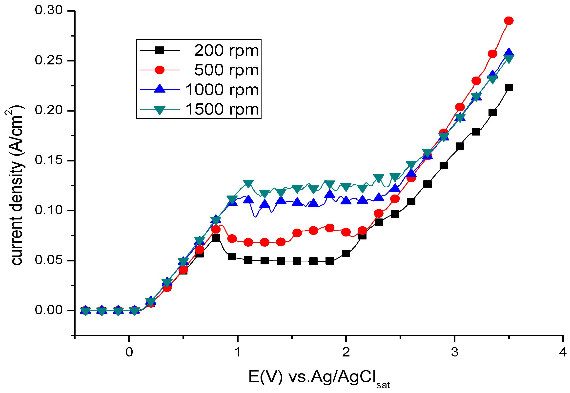
3.1. Anodic Polarisation Behaviour

Figure 1 shows the anodic polarisation curves of the brass-RCE at different rotational speeds in the 70% H3PO4 solution. As shown in Figure 1, limiting-current plateaus in the anodic polarisation curves of the brass-RCE with a potential range of approximately 1 V can be clearly seen at different rotational speeds. The potential range of the limiting current plateau gradually shifts to relatively noble potential with an increase in the rotational speed of the brass-RCE. Based on the results of the anodic polarisation test, the current-density values of transition peaks and limiting-current plateaus at different rotating speeds are listed in Table 1. The limiting-current density of the brass-RCE increases with increasing rotational speed. These results are in agreement with the anodic dissolution behaviour of the RCE under a diffusion-controlled mechanism in which the mass transfer rate increases with increasing rotating speed [21]. As shown in Figure 1, a transition peak can be observed in each anodic polarisation curve, decreasing its anodic current density from kinetic- to diffusion-controlled dissolution. This suggests that there could be a viscous layer or a salt film formed on the brass-RCE surface, impeding its anodic dissolution rate in the transition from active- to diffusion-controlled dissolution. By visual observation, a blue layer, which could be regarded as a Cu2+-rich layer in a transparent solution, developed on the brass-RCE surface at different rotational speeds when the polarised potential was at or above the transition peak.
Based on our previous study of the EP behaviour of 73 brass with a rotating disc electrode (RDE) [20], we confirmed that a transition peak can be found at a rotational speed lower than 1000 rpm. In this study, however, an obvious transition peak was detected with brass-RCE at 1500 rpm. This result implies that the Cu2+-rich layer could exist on the brass-RCE surface at a rotational speed of 1500 rpm, but not on the brass-RDE. The effect of this Cu2+-rich layer on the EP behaviour of the brass-RCE will be discussed in the following section.

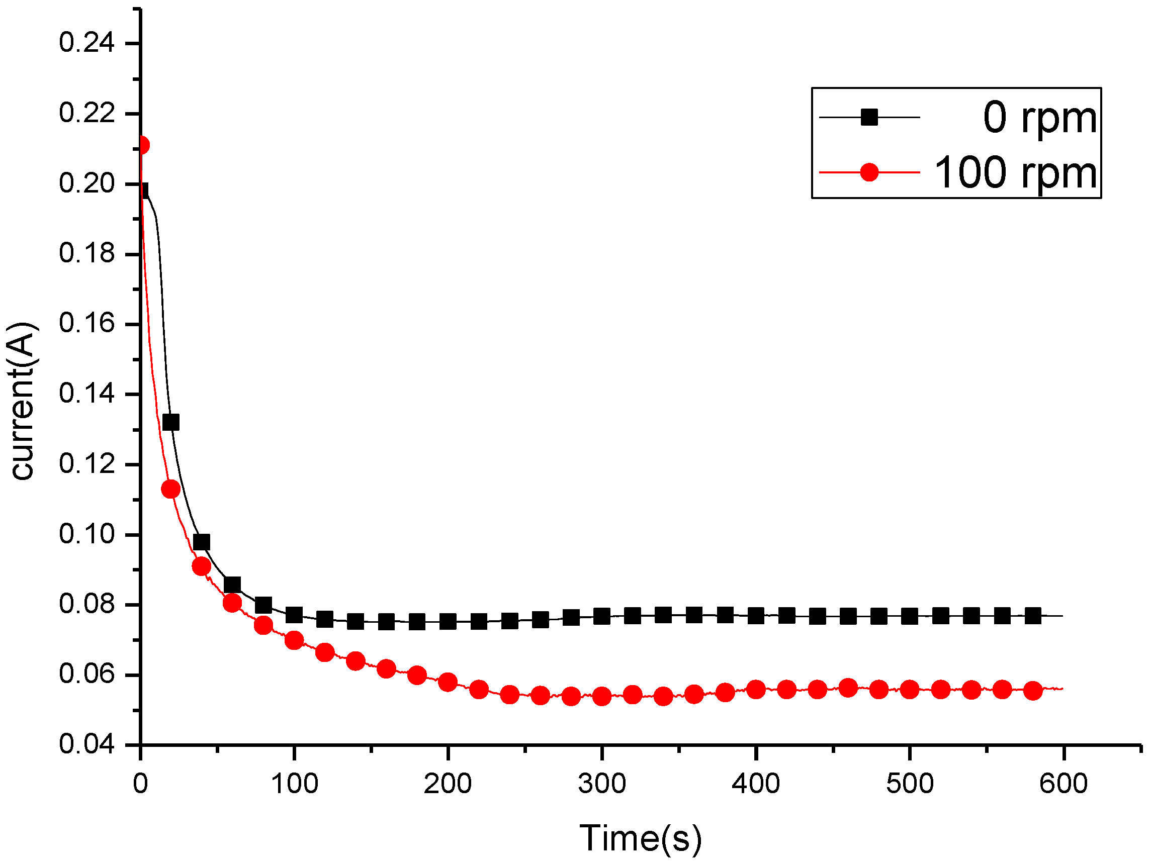
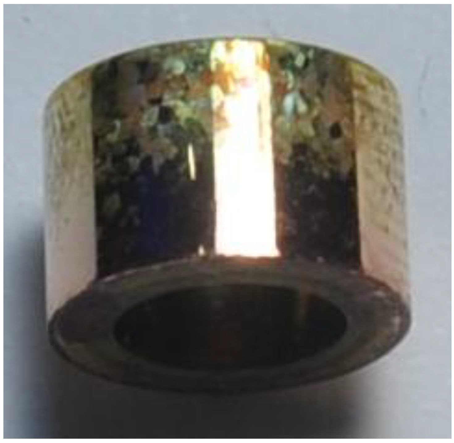
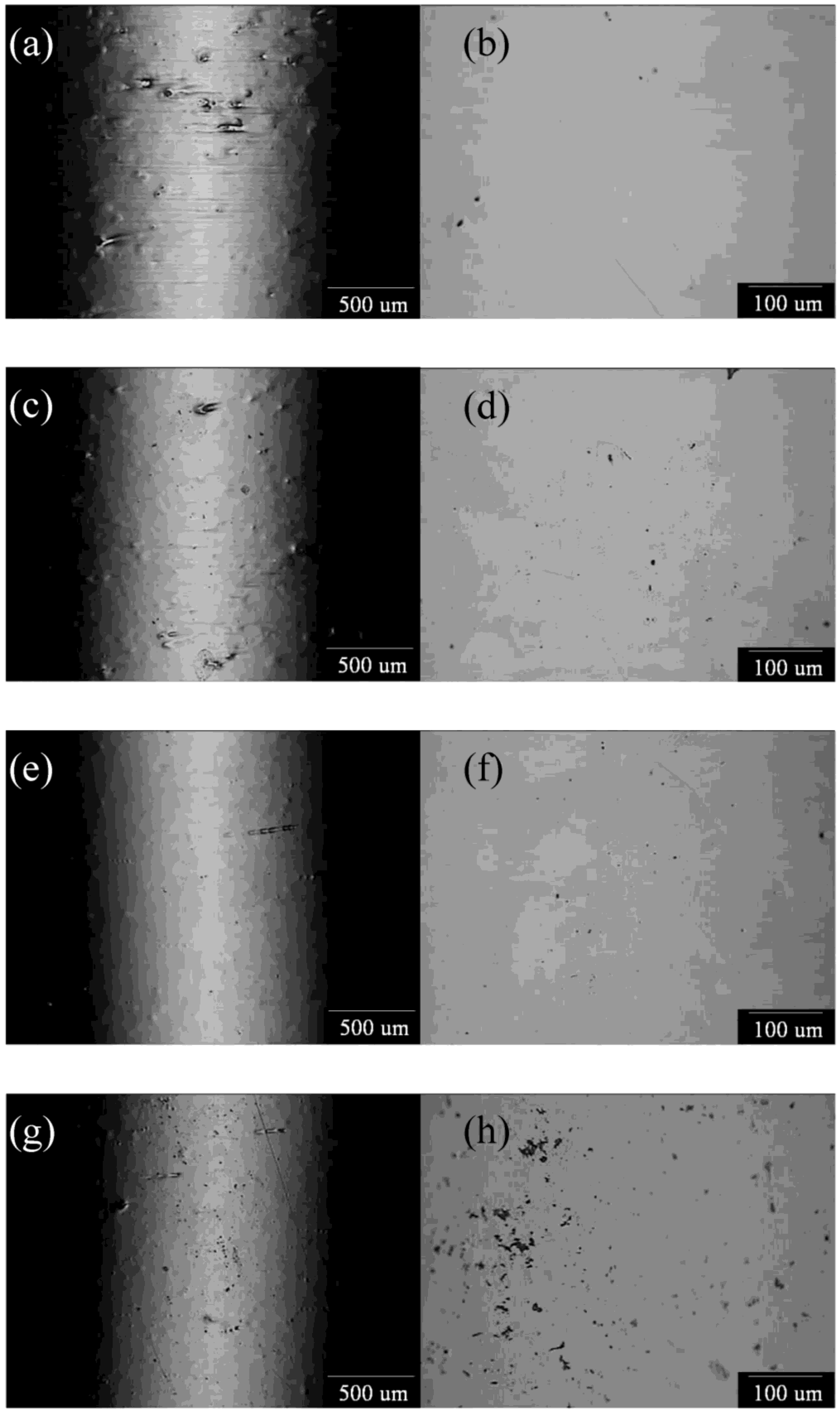
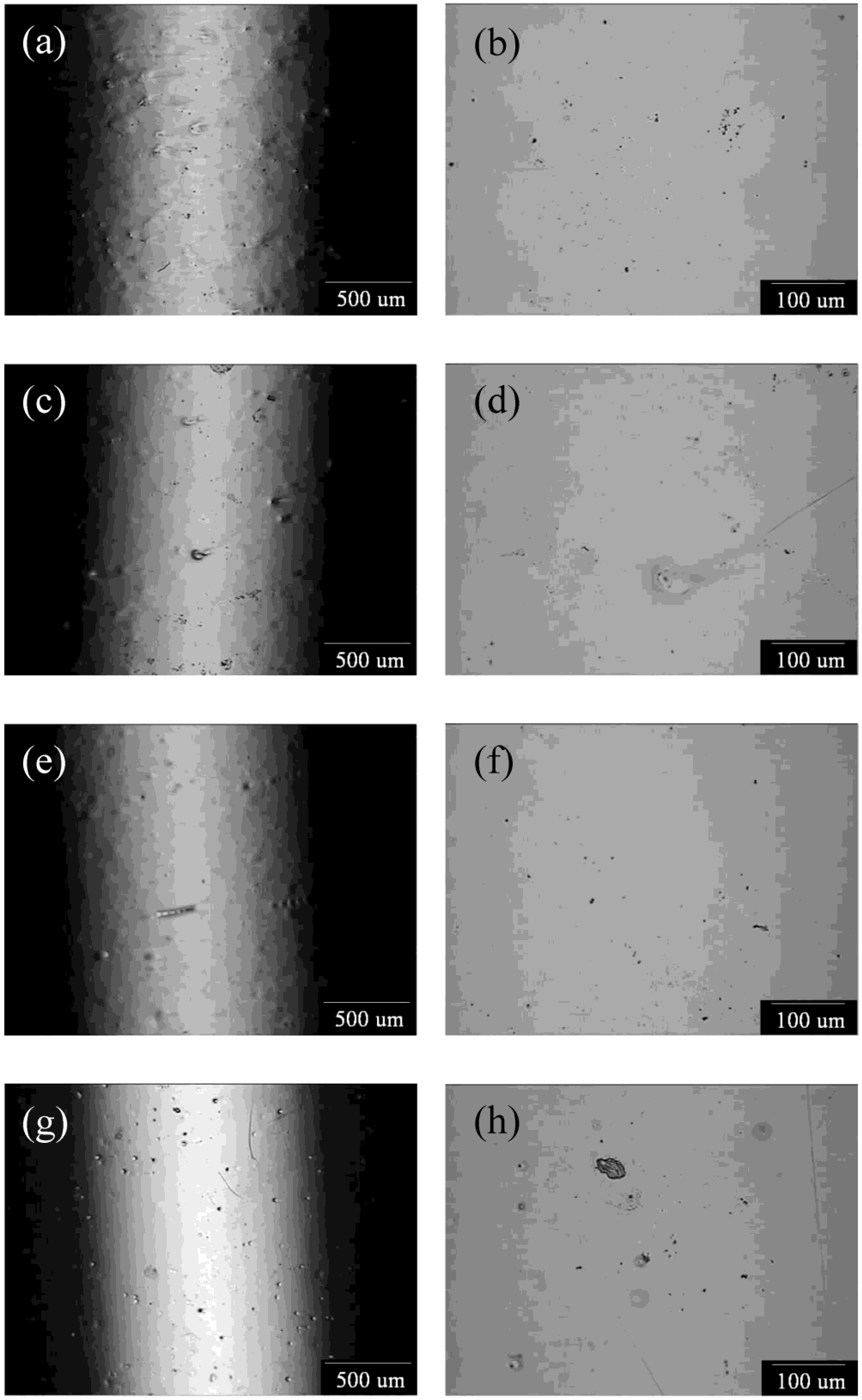
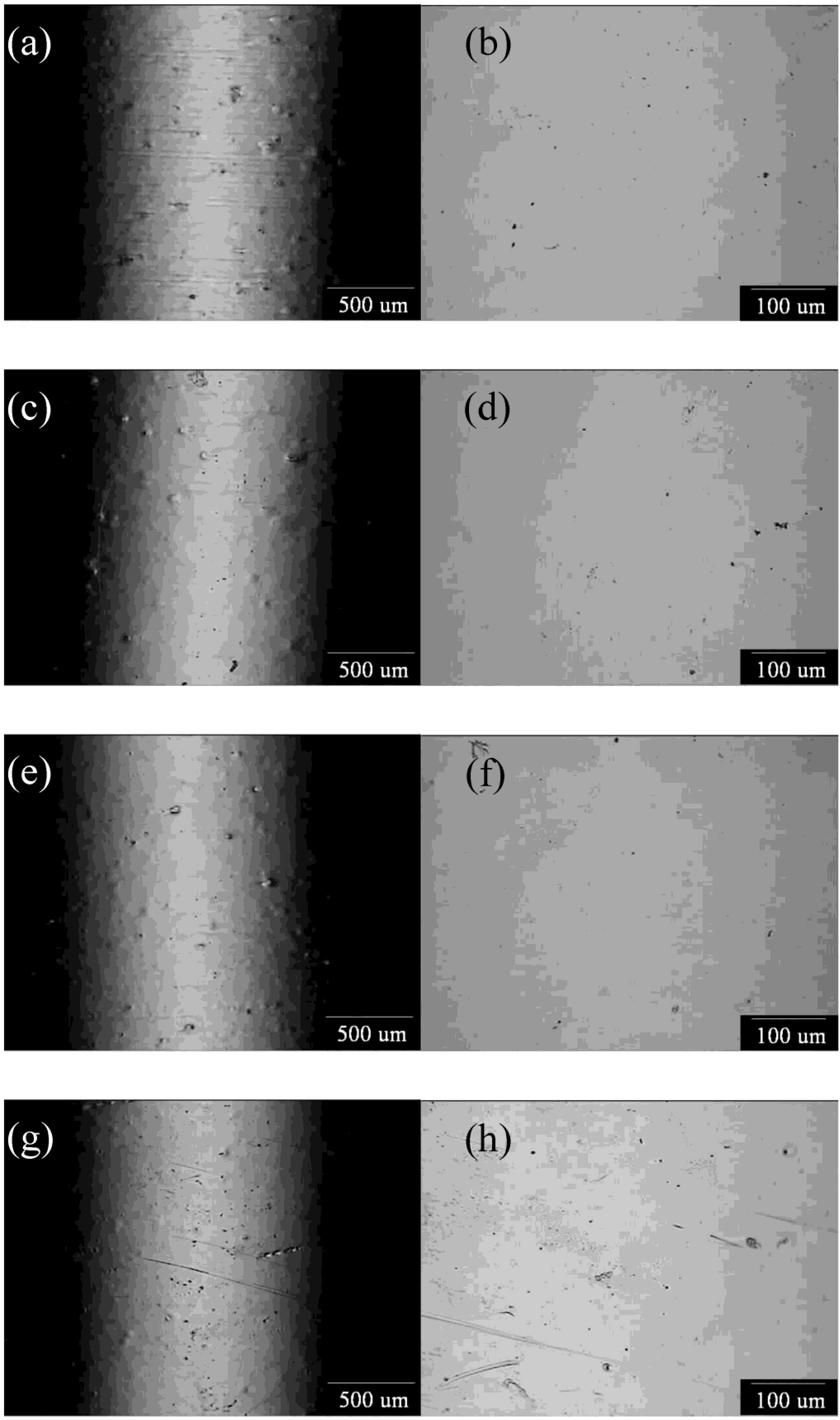
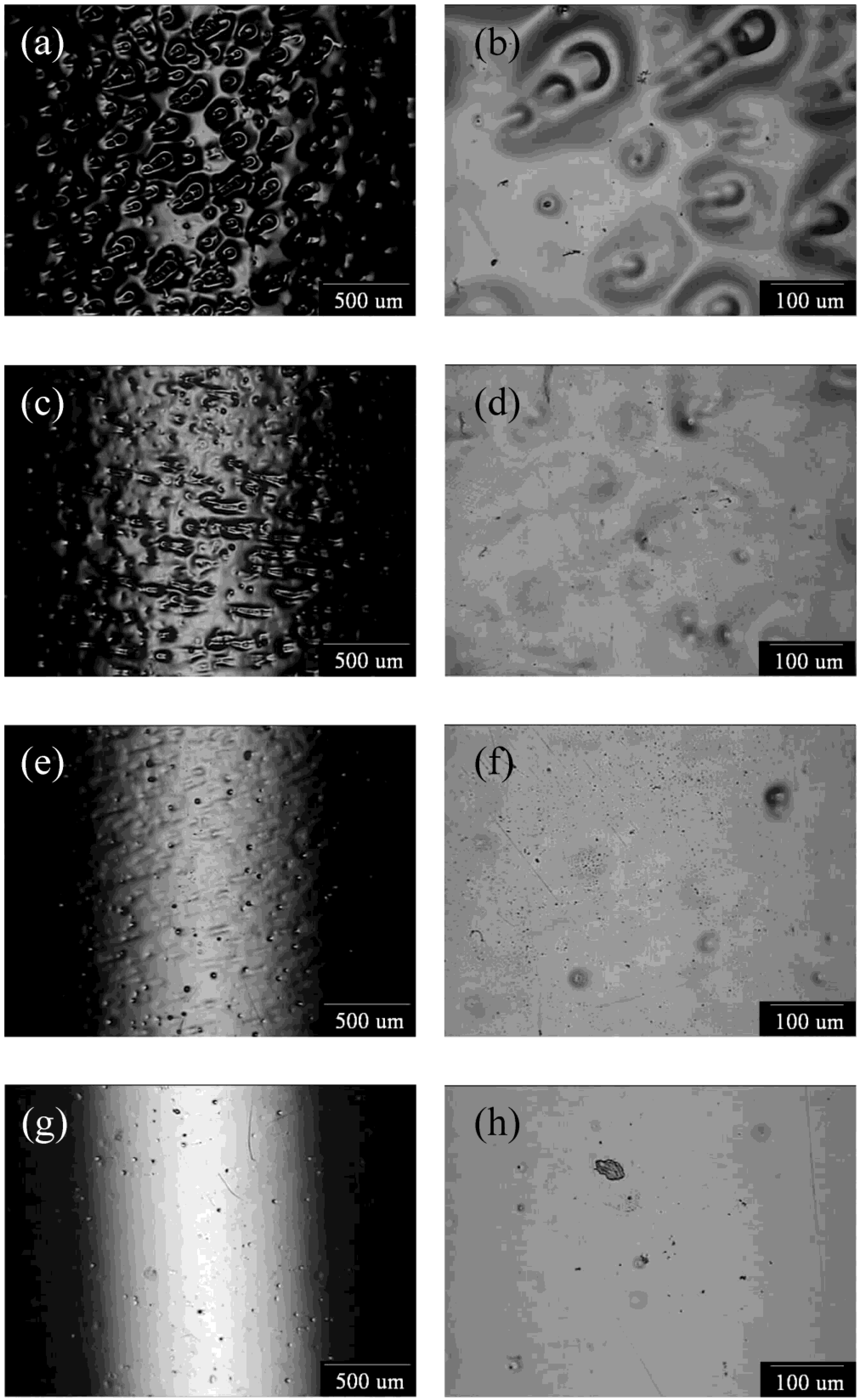
3.2. Potentiostatic Polishing on the Limiting-Current Plateau

To study the EP behaviour, the brass-RCE was potentiostatically etched at four potentials located at the transition-peak and the start, middle, and end potentials corresponding to its limiting-current plateau. The polarised potentials were determined according to the anodic polarisation curves with a scan rate of 5 mV·s−1 and are shown in Figure 1. The EP potentials corresponding to the above-mentioned four specified potentials at different rotational speeds are listed in Table 2.
The surface morphologies in low and high magnifications for the left-side and right-side figures, respectively, of the brass-RCEs potentiostatically etched at their transition peaks at rotational speeds of 200, 500, 1000, and 1500 rpm are shown in Figure 2a–d, respectively. As shown in Figure 2a–d, a visually shiny surface of the brass-RCE could be achieved after anodic etching at the transition-peak potential. However, parts of the brass-RCE were not well levelled at a rotational speed lower than 500 rpm, developing a few shallow pits on the brass-RCE surface. Some deep pits can be found on the surface of brass-RCE after potentiostatic etching at 1500 rpm. Based on the above-mentioned results, the brass-RCE surface cannot be satisfactorily electropolished when the brass-RCE is potentiostatically etched at the transition-peak potential at rotational speeds lower than 500 and higher than 1500 rpm.
In our previous study [20], the grain boundaries were severely etched with a brass-RDE after potentiostatic etching at their transition peaks. Conversely, grain boundaries were faintly etched when the brass-RCE polarised at transition potentials at different rotational speeds. This obviously dissimilar effect can be attributed to the shape difference between the RDE and the RCE. According to our previous study, we found that the blue Cu2+-rich layer is essential to obtain a levelled and brightened surface. This observation suggests that coverage of the Cu2+-rich layer on the brass-RDE and brass-RCE could be different. A fully covered Cu2+-rich layer could be expected on the surface of the brass-RCE because the EP effect of brass-RCE is obviously better than that of brass-RDE.
The surface morphologies of the brass-RCEs potentiostatically etched at the start of the limiting-current plateau with different rotational speeds are shown in Figure 3a–d. As for those polarised at transition potentials, all brass-RCEs were visually bright after potentiostatic etching at the start of the limiting-current plateau. A few small etched pits appeared on the surface of brass-RCE at a rotational speed of 1500 rpm. Unlike the EP effect on the brass-RDE at 1500 rpm, the grain boundaries were not etched with brass-RCE when EP was at the start potential of its limiting-current plateau. This observation indicates that EP at the start potential of its limiting-current plateau is available with RCE-brass at a rotational speed from 200 to 1500 rpm.
As shown in Figure 4a–d, a brightened and levelled surface could be obtained after potentiostatic etching in the middle of its limiting-current plateau at rotational speeds ranging from 200 to 1500 rpm. From experimental results shown in Figure 4a–d, a well electropolished surface could be achieved by means of brass-RCE when the EP is performed from the start to the middle potentials in its limiting-current plateau. According to the potentiostatic test, a well-polished surface can be achieved after electropolishing at potentials located at the transition peak and the start and middle in the limiting-current plateau. However, a few small pits the size of a few micrometers were observed on the brass-RCE surface. This is possibly the result of the enrichment of the Zn element beneath the oxide/hydroxide films on the brass surface [19].
Figure 5a–d shows the surface morphologies of the brass-RCEs potentiostatically etched at the end of their limiting-current plateau at different rotational speeds. A flow-streak feature and some pits were observed when the brass-RCE was potentiostatically etched at the end of the limiting-current plateau at rotational speeds of 200 and 500 rpm. However, these flow streaks were not observed on the brass-RCE surface potentiostatically etched at a rotational speed of 1000 rpm or higher, except for a few shallow pits. Because an oxygen-evolution reaction could occur through potentiostatic etching at the end of the limiting-current plateau, it can be expected that flow streaks and pits were formed due to the formation and evolution of oxygen bubbles during potentiostatic etching. The formation mechanism of flow streaks on brass-RDE was proposed in our previous study [20] in which oxygen bubbles move intermittently along the flow stream on the brass surface, leading to etching of a bubble-flow-streak feature. Because flow streaks were not found, this means that oxygen bubbles escape easily from the surface of brass-RCE at a rotational speed higher than 1000 rpm.

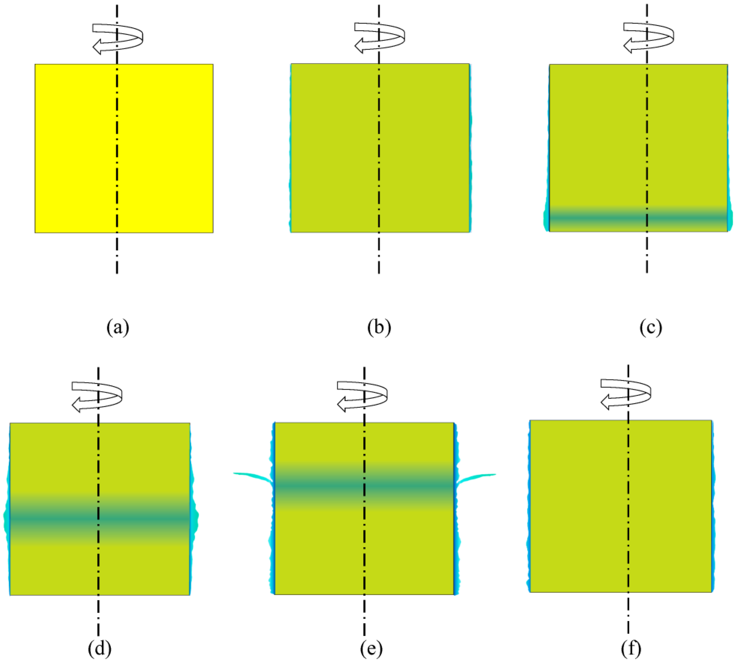
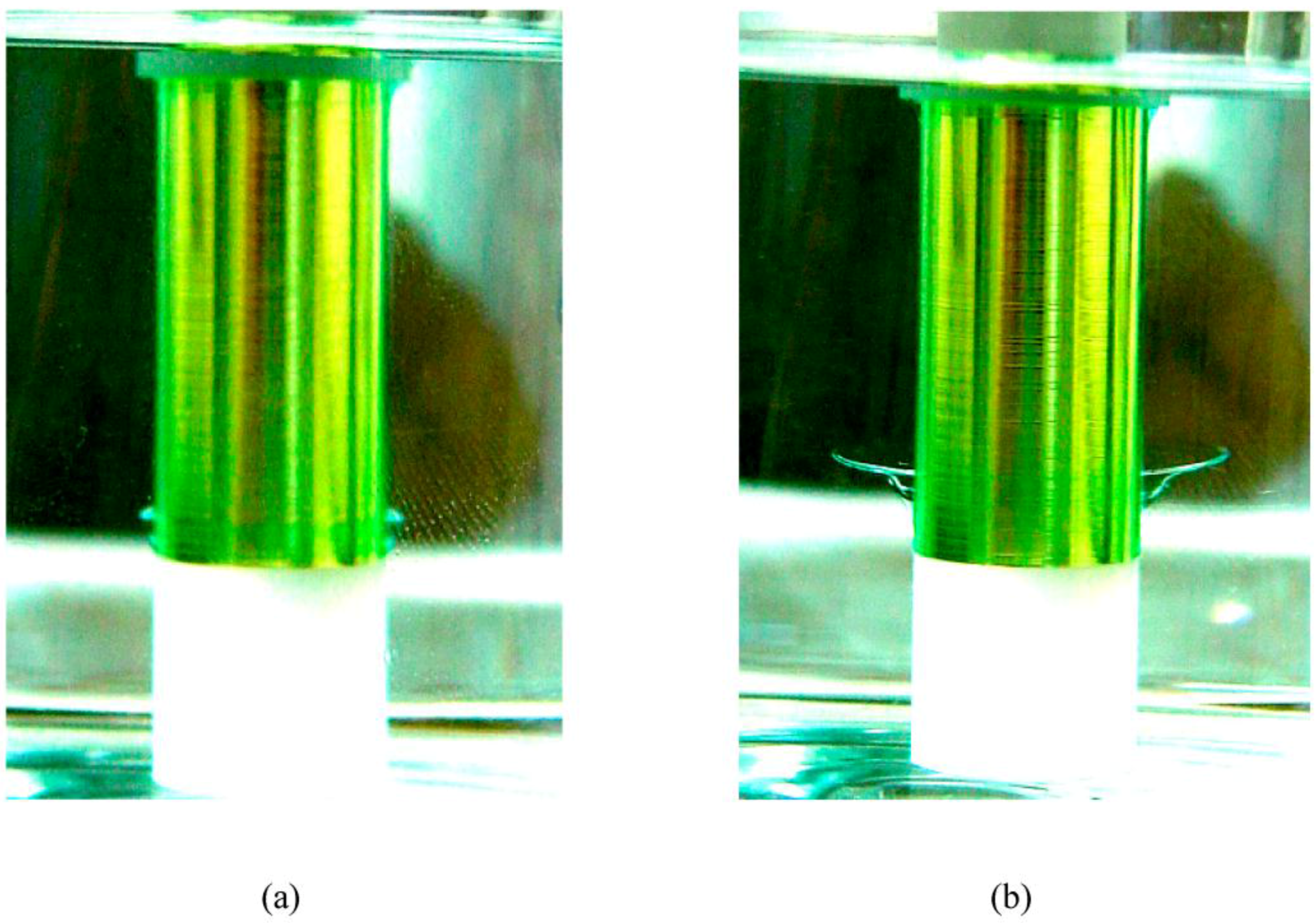
3.3. Effect of the Blue Cu2+-Rich Layer

Figure 6 shows the variation of the anodic current densities of brass-RCEs at rotational speeds of 0 and 100 rpm during potentiostatic etching in the middle of a limiting-current plateau at which the brass-RCE can be well electropolished in a rotational speed range from 200 to 1500 rpm. Interestingly, as shown in Figure 6, the anodic current density of the non-rotational brass-RCE is obviously higher than that of the brass-RCE at 100 rpm. It is well known that in EP a metal electrode is polarised in the limiting-current plateau in which the anodic dissolution is under a mass-transfer controlled process [22,23,24]. The limiting-current density of the RCE increases with increasing rotational speed or an increasing mass-transfer rate from the reacted chemical species in the solution to the RCE surface. This can be evidenced from the experimental results shown in Figure 1. This result implies that the EP mechanisms for the RCEs at 0 and 100 rpm must be different. Because the Cu2+-rich layer formed on the brass-RCE impedes the anodic dissolution rate, a lack of the layer on the upper side of the non-rotational brass-RCE can be expected. This result leads to having a relatively high anodic current density during EP.
To clarify the effect of the blue Cu2+-rich layer on the brass-RCE during EP, the brass-RCE was potentiostatically etched without rotation in the middle of the limiting-current plateau. Because the specific gravity of the Cu2+-rich layer is obviously higher than that of the EP solution, 70 vol % H3PO4, the Cu2+-rich layer formed on the upper site of the RCE will fall directly downward to the lower site of the brass-RCE during potentiostatic etching. That is, there will be a lack of the Cu2+-rich layer on the upper side of stagnate brass-RCE during EP. Figure 7 shows the surface morphology of the brass-RCE electropolished without rotation. From the micrograph shown in Figure 7, a visually bright surface of brass-RCE could be achieved after EP. Moreover, a distinctly different effect of EP on the upper and lower sites of the brass-RCE was found. On the upper site, the grain boundaries of the brass-RCE were obviously etched, showing its grain structure, indicating that the upper site was not well electropolished. Alternatively, a brightened and levelled Cu deposited RCE was found on the lower site. Because the Cu2+-rich layer fell from an upper site down to a lower site, the lower site of the non-rotational brass-RCE was well covered by abundant Cu2+ ions during EP. This behaviour indicates that the Cu2+-rich layer on the brass-RCE is helpful for EP.
A Cu2+-rich layer can be clearly seen on the brass-RCE with a rotational speed of 100 rpm or higher during EP. Due to the effect of gravity, the blue Cu+2-rich layer cannot maintain its stick state on the surface of the brass-RCE without rotation. Based on the experimental results, the rotating brass-RCE must be fully covered with a blue Cu2+-rich layer during EP. A rod-climbing phenomenon of the Cu+2-rich layer can be observed during EP. This phenomenon can be illustrated from Figure 8a–f. During potentiostatic etching, a well-covered blue Cu2+-rich layer was initially developed on the brass-RCE (see Figure 8b). Due to the effect of gravity, the outer part of the Cu+2-rich layer fell down and concentrated to be a semi-sphere on the lower site of the brass-RCE by further potentiostatic etching (see Figure 8c,d). Interestingly, the semi-sphere went upwards along the surface of the brass-RCE, the rod climbing phenomenon, during potentiostatic etching (see Figure 8d). This rod-climbing phenomenon is evidenced in Figure 9a,b. As shown in Figure 8e, the semi-sphere climbed to approximately half the height of the brass-RCE, and it was unstable, scattering into a thin mushroom shape in the EP solution. When the semi-sphere diminished, a thin Cu+2-rich layer was still found on the rotating brass-RCE (see Figure 8a,f), and the repeated formation sequences of semi-sphere, rod climbing, and scattering were observed. Because the Cu+2-rich layer was found on the brass-RCE at 1500 rpm, an obvious transition peak was detected from its anodic polarisation curve (see Figure 1). Alternatively, the transition peak was not seen from the brass-RDE at 1500 rpm [20]. Thus, the EP effect on the brass-RCE potentiostatically etched at the transition peak is much better than that on the brass-RDE.
The rod-climbing behaviour was studied using the flow-field simulation method [25]. According to the simulation, the Cu2+-rich layer was rolled up by the upward flow. The rolled up semi-sphere went up with the upward flow until it met the downward flow, in which the outer part of Cu2+-rich layer fell downward due to gravity. Next, the semi-sphere was flushed into a thin mushroom shape and spread into the 70 vol % H3PO4 solution. Detailed results of the simulation will be discussed and published in a related journal. Because the Cu2+-rich layer can be developed on the rotating brass-RCE, a well electropolished surface can be easily achieved from the brass-RCE.

4. Conclusions

Potentiostatic etching of the brass-RCE was performed at potentials corresponding to the transition peak and in the start, the middle, and the end sites in its limiting-current plateau. Due to a stick layer of Cu2+ ions on the brass-RCE, the electropolishing effect was easier to achieve on the brass-RCE than it was on the brass-rotating disc electrode. During electropolishing with a rotating brass-RCE, rod climbing of the Cu2+-rich layer was seen. An upward stream was developed along the brass-RCE, and a Cu2+-rich semi-sphere climbed along the brass-RCE surface, resulting in good coverage of the Cu2+-rich layer and improvement of its electropolishing effect.

Author Contributions

C.A. Huang wrote the manuscript, gave a discussion about experimental results, and responded reviewers’ comments. J.Y. Chen had conducted experiments and observed the EP behaviour. M.T. Sun simulated the flow field to explain the rod climbing behaviour during EP of the rotating cylinder.

Conflicts of Interest

The authors declare no conflict of interest.

References

  1. Zhang, J.; Tang, N.; Shang, Y.-J.; Xu, F. Effect of alloying elements on corrosion resistance of brass and function mechanisms. Corros. Prot. 2012, 33, 605–609. [Google Scholar]
  2. Kwon, G.D.; Kim, Y.W.; Moyen, E.; Keum, D.H.; Lee, Y.H.; Baik, S.; Pribat, D. Controlled electropolishing of copper foils at elevated temperature. Appl. Surf. Sci. 2014, 307, 731–735. [Google Scholar] [CrossRef]
  3. Landolt, D. Fundamental aspects of electropolishing. Electrochim. Acta 1987, 32, 1–11. [Google Scholar] [CrossRef]
  4. Matlosz, M.; Landolt, D. Shape changes in electrochemical polishing: The effect of temperature on the anodic leveling of Fe-24Cr. J. Electrochem. Soc. 1989, 136, 919–929. [Google Scholar] [CrossRef]
  5. Gabe, D.R. Electropolishing of copper and copper-based alloys in ortho-phosphoric acid. Corros. Sci. 1972, 12, 113–120. [Google Scholar] [CrossRef]
  6. Iskander, S.S.; Mansour, I.A.S.; Sedahmed, G.H. Electropolishing of brass alloys in phosphoric acid. Surf. Technol. 1980, 10, 357–361. [Google Scholar] [CrossRef]
  7. Awad, A.M.; Ghany, N.A.A.; Dahy, T.M. Removal of tarnishing and roughness of copper surface by electropolishing treatment. Appl. Surf. Sci. 2010, 256, 4370–4375. [Google Scholar] [CrossRef]
  8. Vidal, R.; West, A.C. Copper electropolishing in concentrated phosphoric acid I. Experimental findings. J. Electrochem. Soc. 1995, 142, 2682–2689. [Google Scholar] [CrossRef]
  9. Varenko, E.S.; Loshkarev, Y.M.; Tarasova, L.P. Surface roughness of brass during electropolishing in orthophosphoric acid solutions. Sov. Electrochem. 1991, 27, 105–107. [Google Scholar]
  10. Li, D.; Li, N.; Xia, G.; Zheng, Z.; Wang, J.; Xiao, N.; Zhai, W.; Wu, G. An in-situ study of copper electropolishing in phosphoric acid solution. Int. J. Electrochem. Sci. 2013, 8, 1041–1046. [Google Scholar]
  11. Han, G.H.; Gunes, F.; Bae, J.J.; Kim, E.S.; Chae, S.J.; Shin, H.-J.; Choi, J.-Y.; Pribat, D.; Lee, Y.H. Influence of copper morphology in forming nucleation seeds for graphene growth. Nano Lett. 2011, 11, 4144–4148. [Google Scholar] [CrossRef] [PubMed]
  12. Jacquet, P.A. On the anodic behavior of copper in aqueous solutions of orthophosphoric acid. J. Electrochem. Soc. 1936, 69, 629–655. [Google Scholar] [CrossRef]
  13. Jacquet, P.A. Electrolytic method for obtaining bright copper surfaces. Nature 1935, 135, 1076. [Google Scholar] [CrossRef]
  14. Logie, S.; Chick, J.; Campbell, M.; Bilbao, S. The influence of bore profile on slurred transients in brass instruments. In Proceedings of the Forum Acusticum 2011, Aalborg, Denmark, 26 June–1 July 2011.
  15. Du, B.; Suni, I.L. Mechanistic studies of cu electropolishing in phosphoric acid electrolytes. J. Electrochem. Soc. 2004, 151, 375–378. [Google Scholar] [CrossRef]
  16. Huo, J.; Solanki, R.; McAndrew, J. Study of anodic layers and their effects on electropolishing of bulk and electroplated films of copper. J. Appl. Electrochem. 2004, 34, 305–314. [Google Scholar] [CrossRef]
  17. Glarum, S.H.; Marshall, J.H. The anodic dissolution of copper into phosphoric acid. J. Electrochem. Soc. 1985, 132, 2872–2878. [Google Scholar] [CrossRef]
  18. West, A.C.; Deligianni, H.; Andricacos, P.C. Electrochemical planarization of interconnect metallization. IBM J. Res. Dev. 2005, 49, 37–48. [Google Scholar] [CrossRef]
  19. Gentile, M.; Koroleva, E.V.; Skeldom, P.; Thompson, G.E.; Bailey, P.; Noakes, T.C.Q. Influence of pre-treatment on the surface composition of Al-Zn alloys. Corros. Sci. 2010, 52, 688–694. [Google Scholar] [CrossRef]
  20. Huang, C.A.; Chang, J.H.; Zhao, W.J.; Huang, S.Y. Examination of the electropolishing behaviour of 73 brass in a 70% H3PO4 solution using a rotating disc electrode. Mater. Chem. Phys. 2014, 146, 230–239. [Google Scholar] [CrossRef]
  21. Pérez, T.; Nava, J.L. Simulation of turbulent flow of a rotating cylinder electrode. Influence of using plates and concentric cylinder as counter electrodes. Int. J. Electrochem. Soc. 2013, 8, 4690–4699. [Google Scholar]
  22. Datta, M.; Landolt, D. On the role of mass transport in high rate dissolution of iron and nickel in ECM electrolytes—I. Chloride solutions. Electrochim. Acta 1980, 25, 1255–1262. [Google Scholar] [CrossRef]
  23. Datta, M.; Landolt, D. On the role of mass transport in high rate dissolution of iron and nickel in ECM electrolytes—II. Chlorate and nitrate solutions. Electrochim. Acta 1980, 25, 1263–1271. [Google Scholar] [CrossRef]
  24. Datta, M.; Vega, L.F.; Romankiw, L.T.; Duby, P. Mass transport effects during electropolishing of iron in phosphoric-sulfuric acid. Electrochim. Acta 1992, 37, 2469–2475. [Google Scholar] [CrossRef]
  25. Sun, M.T.; Huang, C.A.; Huang, S.Y. The rod-climbing phenomenon of the viscous film on the surface of brass cylinder during electropolishing in the aqueous phosphoric acids. In Proceedings of the 211th ECS Meeting, Chicago, IL, USA, 6–10 May 2007; p. 552.
Figure 1. Anodic polarization curves of the brass-rotating cylinder electrode (RCE) at different rotational speeds in the 70 vol % H3PO4 solution with a scan rate of 5 mV/s.
Metals 07 00030 g001
Figure 2. Surface morphologies of brass-RCEs potentiostatically etched at their transition peaks at rotational speeds of (a,b) 200; (c,d) 500; (e,f) 1000; and (g,h) 1500 rpm.
Metals 07 00030 g002
Figure 3. Surface morphologies of brass-RCEs potentiostatically etched at the start potentials of their limiting-current plateaus at rotational speeds of (a,b) 200; (c,d) 500; (e,f) 1000; and (g,h) 1500 rpm.
Metals 07 00030 g003
Figure 4. Surface morphologies of the brass-RCEs potentiostatically etched in the middle of their limiting-current plateaus at rotational speeds of (a,b) 200; (c,d) 500; (e,f) 1000; and (g,h) 1500 rpm.
Metals 07 00030 g004
Figure 5. Surface morphologies of brass-RCEs potentiostatically etched at the end of their limiting-current plateaus at rotational speeds of (a,b) 200; (c,d) 500; (e,f) 1000; and (g,h) 1500 rpm.
Metals 07 00030 g005
Figure 6. Variation in the anodic current densities of brass-RCEs potentiostatically etched in the middle of their limiting-current plateaus at rotational speeds of 0 and 100 rpm.
Metals 07 00030 g006
Figure 7. Surface morphology of the brass-RCE potentially etched in the middle of the limiting-current plateau.
Metals 07 00030 g007
Figure 8. Schematic illustration of the rod-climbing phenomenon of the Cu+2-rich layer (a) initial electropolishing; (b) full coverage; (c,d) rod-climbing; (e) formation a thin mushroom-shaped stream; (f) full coverage.
Metals 07 00030 g008
Figure 9. (a) Formation of the semi-sphere of the Cu2+-rich layer in the bottom site of the brass-RCE; and (b) thin mushroom-shaped layer developed on the brass-RCE during electropolishing (EP).
Metals 07 00030 g009
Table 1. Values of limiting current densities (Il) and transition current peaks (Ip) at different rotating speeds.
Rotating Speed (rpm)Il (A/cm2)Ip (A/cm2)
2000.04940.0727
5000.07380.0855
10000.10490.1142
15000.12080.1278
Table 2. Potentials corresponding to transition peak and the start, middle, and end of the limiting-current plateau at different rotating speeds.
Rotating Speed (rpm)Vp (V)Vs (V)Vm (V)Ve (V)
2000.821.261.541.84
5000.850.971.512.04
10001.071.211.722.22
15001.11.221.722.22
Vp: potential of transition-peak, Vs: start potential of limiting-current plateau, Vm: middle potential of limiting-current plateau, Ve: end potential of limiting-current plateau. All potentials shown in above table are compared to Ag/AgClsat (0.197 V vs. SHE).

