Metallurgical Challenges in Carbon Nanotube-Reinforced Metal Matrix Nanocomposites

 , ,
, , 
Abstract
:
1. Introduction
- (i)
- Favorable dispersion of CNTs throughout the matrix. A composite with improved properties will be obtained when the reinforcements are uniformly distributed through the matrix. Otherwise, the micro-pores as well as agglomerated particles may form all over the microstructure [13,14]. To overcome this challenge, a broad spectrum of dispersion methods is developed. Among these techniques, the mechanical methods [15], surface treatment [16], and chemical methods [17] are the most conventional. Each of these techniques has their own advantages and disadvantages, being discussed in the next sections.
- (ii)
- Unfavorable chemical reaction of CNTs with matrix at high pressures, elevated temperatures, and induced strains. It is usually accompanied by the formation of defects. On the other words, to thermally decompose CNTs in exposure to a metallic matrix, the presence or formation of defects is required. It is shown that the thermal decomposition of CNTs can bilaterally affect the final properties of the nanocomposites. In other words, the final properties strongly depend on the chemical composition of the formed intermetallics [18,19].
- (iii)
- Poor interfacial adhesion between CNTs and the matrix due to the hydrophobic nature of the CNTs. This shortcoming deteriorates the load bearing between the matrix and CNTs. Moreover, intensive phonon scattering arisen from the insufficient adhesion can significantly enhance the electrical resistivity [20]. It is noteworthy that the interfacial adhesion can be improved whenever a controlled superficial chemical reaction between CNTs and metallic matrix occurs. On the other words, the poor interfacial adhesion can be considered as a sub-challenge under the title of “chemical reaction of CNTs with metallic matrix”. This review paper has adopted such a policy.
- (iv)
- Low compactability of metallic powders. The incorporation of CNTs into metallic powders can decline the relative density of final CNT-metal compacts, if the agglomeration of CNTs is heavy and their volume fraction is exceedingly high.
2. Metallurgical Challenges in CNT-Metal Matrix Nanocomposites
2.1. Dispersion of CNTs (Carbon Nanotubes)
2.1.1. Water Solubilization of CNTs
- (i)
- CNTs may shorten, get severe damages during the functionalization process, and lose their superior mechanical properties and distribution of π-electrons. As a general rule, the electron transport strongly depends on the surface structure of CNTs, because the structural damages can serve as phonon scattering sites and interrupt the transport properties of nanotubes.
- (ii)
- The strong acid solutions normally used for functionalization are hazardous to environment and hard to handle.
- (i)
- They induce no damages to CNTs, so that the electron transportation along the nanotubes remains intact; and
- (ii)
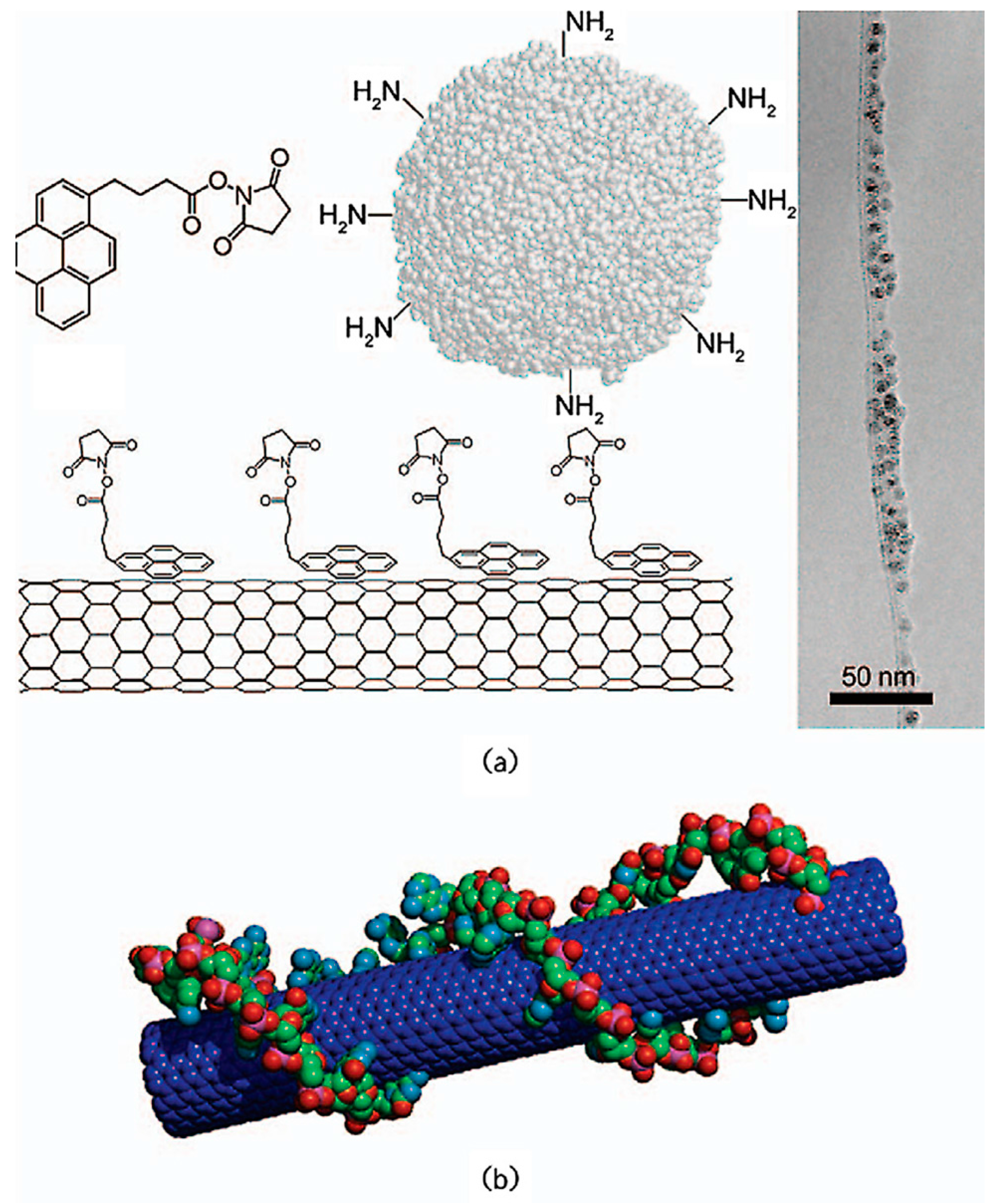
- CNTs are capable of forming an ordered network through the supermolecules acting as non-covalent modifiers. Among these modifiers, polymers and surfactants are the most conventional. These agents can thread themselves onto CNTs (Figure 2a) or wrap themselves around them (Figure 2b) [28,30,31]. Surfactants are also employed for dispersing CNTs in metal matrix nanocomposites.
2.1.2. Dispersion of CNTs into Metallic Systems
Ball Milling
Ultrasonication
The Application of Surfactants
Metallization
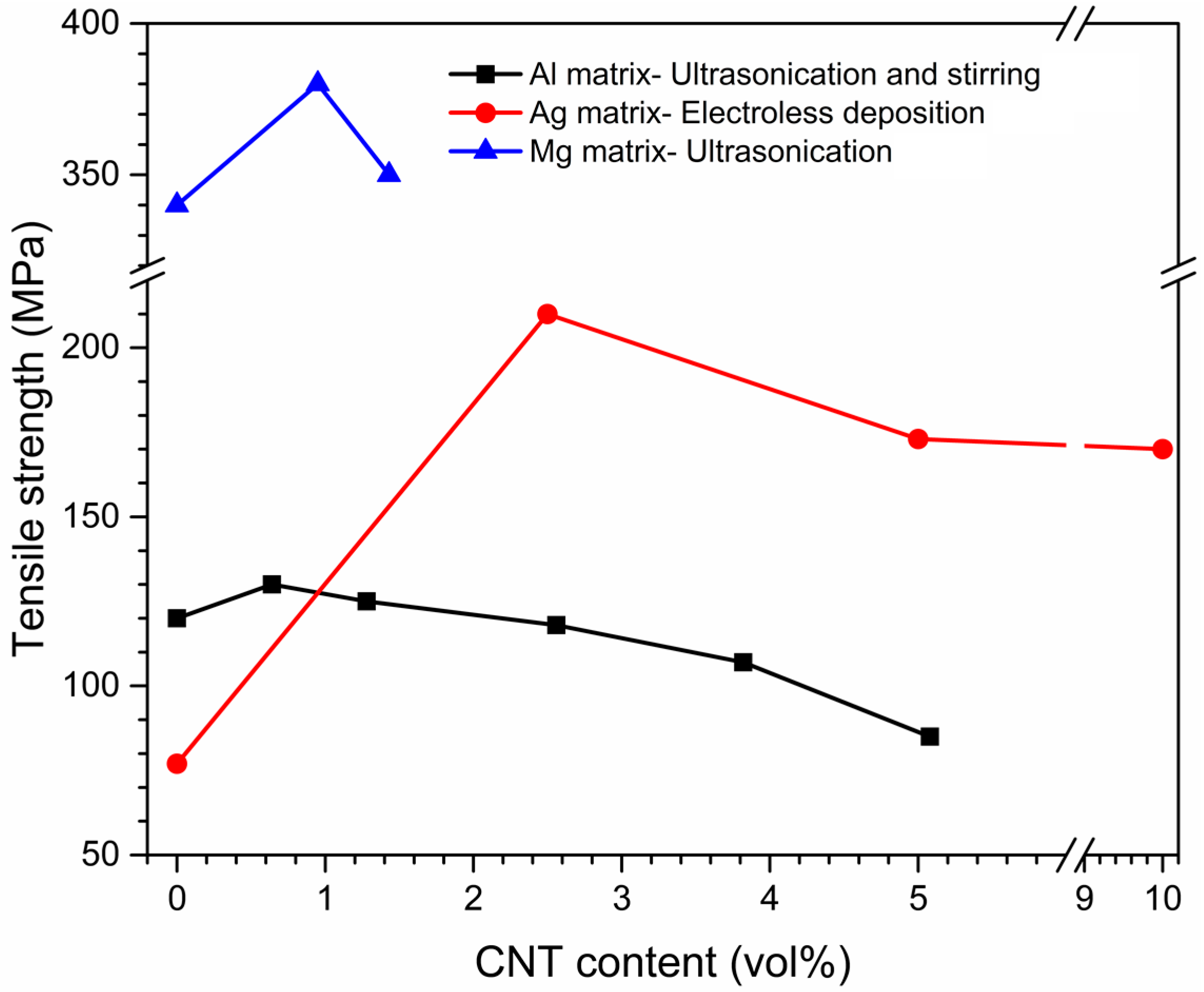
Effects of Dispersion Methods on Physicomechanical Properties
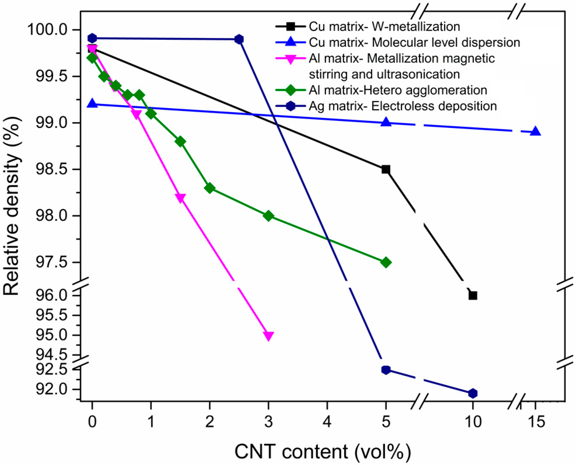
2.2. Consolidation Challenge
2.3. Chemical Reaction with Metallic Matrix
2.3.1. Thermal Decomposition of Pure CNTs
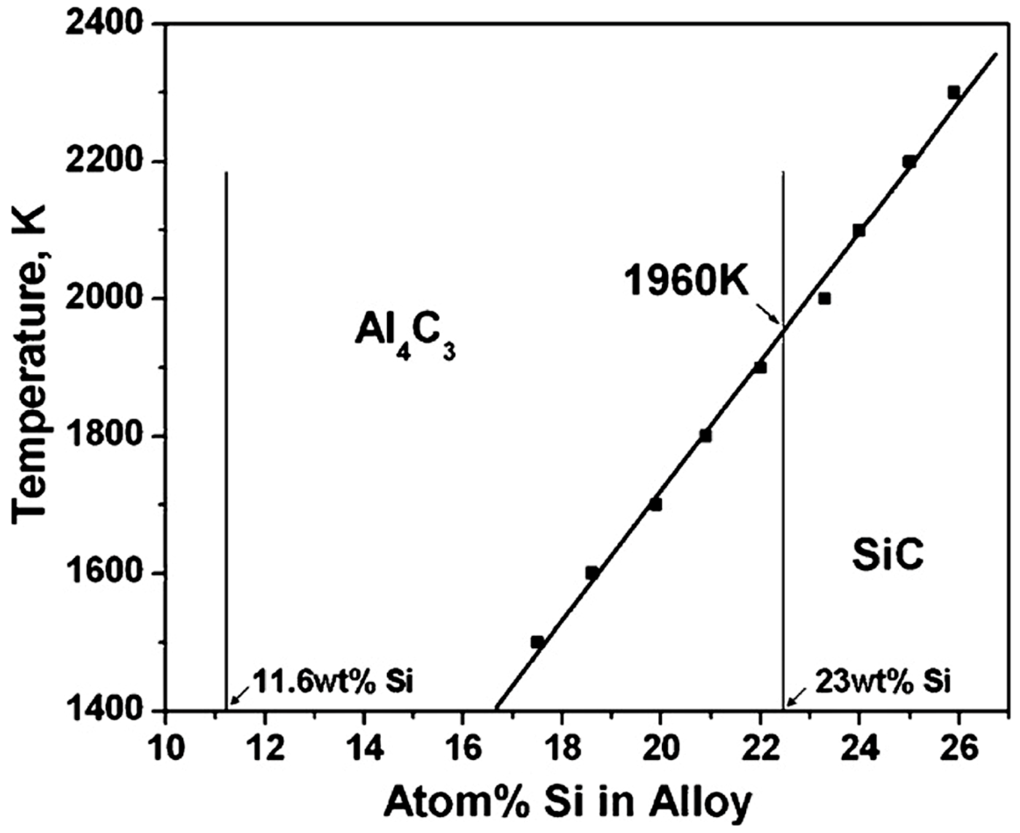
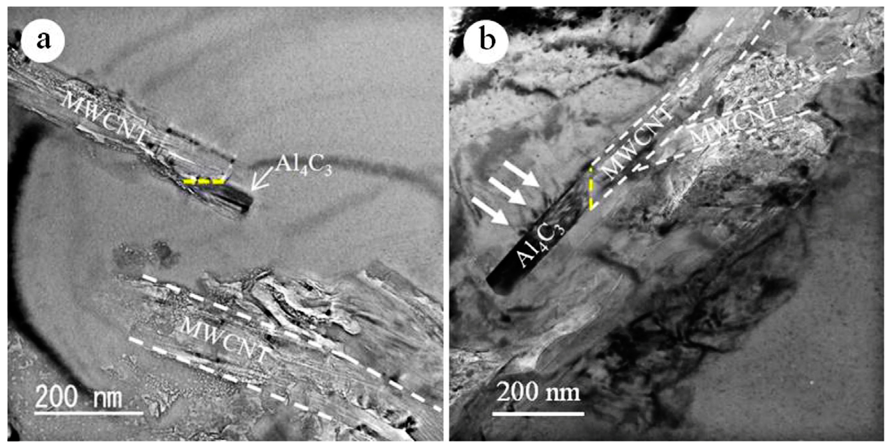
2.3.2. Chemical Reactions
Complete Chemical Reactions
ΔG = −289,512 + 60T, T < 660 °C
Partial Chemical Reaction
3. CNT Pinning-Induced Grain Refinement
4. Conclusions and Outlook
Acknowledgments
Author Contributions
Conflicts of Interest
References
- Iijima, S. Helical microtubules of graphitic carbon. Nature 1991, 354, 56. [Google Scholar] [CrossRef]
- De Volder, M.F.; Tawfick, S.H.; Baughman, R.H.; Hart, A.J. Carbon nanotubes: Present and future commercial applications. Science 2013, 339, 535–539. [Google Scholar] [CrossRef] [PubMed]
- Duclaux, L. Review of the doping of carbon nanotubes (multiwalled and single-walled). Carbon 2002, 40, 1751–1764. [Google Scholar] [CrossRef]
- Kang, S.; Herzberg, M.; Rodrigues, D.F.; Elimelech, M. Antibacterial effects of carbon nanotubes: Size does matter! Langmuir 2008, 24, 6409–6413. [Google Scholar] [CrossRef]
- Kaushik, B.K.; Majumder, M.K. Carbon Nanotube: Properties and Applications. In Carbon Nanotube Based VLSI Interconnects; Springer: Berlin/Heidelberg, Germany, 2015; pp. 17–37. [Google Scholar]
- Ibrahim, K.S. Carbon nanotubes? properties and applications: A review. Carbon Lett. 2013, 14, 131–144. [Google Scholar] [CrossRef]
- Baughman, R.H.; Zakhidov, A.A.; de Heer, W.A. Carbon nanotubes—The route toward applications. Science 2002, 297, 787–792. [Google Scholar] [CrossRef]
- Bakshi, S.; Lahiri, D.; Agarwal, A. Carbon nanotube reinforced metal matrix composites—A review. Int. Mater. Rev. 2010, 55, 41–64. [Google Scholar] [CrossRef]
- Chen, B.; Li, S.; Imai, H.; Jia, L.; Umeda, J.; Takahashi, M.; Kondoh, K. Load transfer strengthening in carbon nanotubes reinforced metal matrix composites via in-situ tensile tests. Compos. Sci. Technol. 2015, 113, 1–8. [Google Scholar] [CrossRef]
- Zapata-Solvas, E.; Gómez-García, D.; Domínguez-Rodríguez, A. Towards physical properties tailoring of carbon nanotubes-reinforced ceramic matrix composites. J. Eur. Ceram. Soc. 2012, 32, 3001–3020. [Google Scholar] [CrossRef]
- Haque, A.; Ramasetty, A. Theoretical study of stress transfer in carbon nanotube reinforced polymer matrix composites. Compos. Struct. 2005, 71, 68–77. [Google Scholar] [CrossRef]
- Nai, M.H.; Wei, J.; Gupta, M. Interface tailoring to enhance mechanical properties of carbon nanotube reinforced magnesium composites. Mater. Des. 2014, 60, 490–495. [Google Scholar] [CrossRef]
- Kim, I.Y.; Lee, J.H.; Lee, G.S.; Baik, S.H.; Kim, Y.J.; Lee, Y.Z. Friction and wear characteristics of the carbon nanotube–aluminum composites with different manufacturing conditions. Wear 2009, 267, 593–598. [Google Scholar] [CrossRef]
- Wu, J.; Zhang, H.; Zhang, Y.; Wang, X. Mechanical and thermal properties of carbon nanotube/aluminum composites consolidated by spark plasma sintering. Mater. Des. 2012, 41, 344–348. [Google Scholar] [CrossRef]
- Morsi, K.; Esawi, A.; Borah, P.; Lanka, S.; Sayed, A. Characterization and spark plasma sintering of mechanically milled aluminum-carbon nanotube (CNT) composite powders. J. Compos. Mater. 2010, 44, 1991–2003. [Google Scholar] [CrossRef]
- Nie, J.H.; Jia, C.C.; Shi, N.; Zhang, Y.F.; Li, Y.; Jia, X. Aluminum matrix composites reinforced by molybdenum-coated carbon nanotubes. Int. J. Miner. Metall. Mater. 2011, 18, 695–702. [Google Scholar] [CrossRef]
- Kurita, H.; Kwon, H.; Estili, M.; Kawasaki, A. Multi-walled carbon nanotube-aluminum matrix composites prepared by combination of hetero-agglomeration method, spark plasma sintering and hot extrusion. Mater. Trans. 2011, 52, 1960–1965. [Google Scholar] [CrossRef]
- Kondoh, K.; Threrujirapapong, T.; Umeda, J.; Fugetsu, B. High-temperature properties of extruded titanium composites fabricated from carbon nanotubes coated titanium powder by spark plasma sintering and hot extrusion. Compos. Sci. Technol. 2012, 72, 1291–1297. [Google Scholar] [CrossRef]
- Paramsothy, M.; Tan, X.; Chan, J.; Kwok, R.; Gupta, M. Carbon nanotube addition to concentrated magnesium alloy AZ81: Enhanced ductility with occasional significant increase in strength. Mater. Des. 2013, 45, 15–23. [Google Scholar] [CrossRef]
- Imai, H.; Kondoh, K.; Li, S.; Umeda, J.; Fugetsu, B.; Takahashi, M. Microstructural and Electrical Properties of Copper–Titanium Alloy Dispersed with Carbon Nanotubes via Powder Metallurgy Process. Mater. Trans. 2014, 55, 522–527. [Google Scholar] [CrossRef]
- Azarniya, A.; Sovizi, S.; Azarniya, A.; Varol, T.; Nithyadharsenia, P.; Hosseini, H.R.M.; Ramakrishna, S.; Reddy, M.V. Physicomechanical properties of spark plasma sintered carbon nanotube-containing ceramic matrix nanocomposites. Nanoscale 2017, 9, 12779–12820. [Google Scholar] [CrossRef] [PubMed]
- Azarniya, A.; Azarniya, A.; Sovizi, S.; Hosseini, H.R.M.; Varol, T.; Kawasaki, A.; Ramakrishna, S. Physicomechanical properties of spark plasma sintered carbon nanotube-reinforced metal matrix nanocomposites. Prog. Mater. Sci. 2017, 90, 276–324. [Google Scholar] [CrossRef]
- Ma, P.C.; Siddiqui, N.A.; Marom, G.; Kim, J.K. Dispersion and functionalization of carbon nanotubes for polymer-based nanocomposites: A review. Compos. Part A Appl. Sci. Manuf. 2010, 41, 1345–1367. [Google Scholar] [CrossRef]
- Islam, M.; Rojas, E.; Bergey, D.; Johnson, A.; Yodh, A. High weight fraction surfactant solubilization of single-wall carbon nanotubes in water. Nano Lett. 2003, 3, 269–273. [Google Scholar] [CrossRef]
- Dai, H. Carbon nanotubes: Opportunities and challenges. Surf. Sci. 2002, 500, 218–241. [Google Scholar] [CrossRef]
- Bandyopadhyaya, R.; Nativ-Roth, E.; Regev, O.; Yerushalmi-Rozen, R. Stabilization of individual carbon nanotubes in aqueous solutions. Nano Lett. 2002, 2, 25–28. [Google Scholar] [CrossRef]
- Wang, Y.; Iqbal, Z.; Mitra, S. Rapidly functionalized, water-dispersed carbon nanotubes at high concentration. J. Am. Chem. Soc. 2006, 128, 95–99. [Google Scholar] [CrossRef] [PubMed]
- Vaisman, L.; Wagner, H.D.; Marom, G. The role of surfactants in dispersion of carbon nanotubes. Adv. Colloid Interface Sci. 2006, 128, 37–46. [Google Scholar] [CrossRef] [PubMed]
- Alig, I.; Pötschke, P.; Lellinger, D.; Skipa, T.; Pegel, S.; Kasaliwal, G.R.; Villmow, T. Establishment, morphology and properties of carbon nanotube networks in polymer melts. Polymer 2012, 53, 4–28. [Google Scholar] [CrossRef]
- Star, A.; Stoddart, J.F.; Steuerman, D.; Diehl, M.; Boukai, A.; Wong, E.W.; Yang, X.; Chung, S.W.; Choi, H.; Heath, J.R. Preparation and properties of polymer-wrapped single-walled carbon nanotubes. Angew. Chem. Int. Ed. 2001, 40, 1721–1725. [Google Scholar]
- Hirsch, A. Functionalization of single-walled carbon nanotubes. Angew. Chem. Int. Ed. 2002, 41, 1853–1859. [Google Scholar] [CrossRef]
- Grumezescu, A. Engineering of Nanobiomaterials: Applications of Nanobiomaterials; William Andrew: Norwich, NY, USA, 2016. [Google Scholar]
- Kwon, H.; Kawasaki, A. Effect of Spark Plasma Sintering in Fabricating Carbon Nanotube Reinforced Aluminum Matrix Composite Materials; INTECH: Vienna, Austria, 2011. [Google Scholar]
- Bakshi, S.R.; Musaramthota, V.; Lahiri, D.; Singh, V.; Seal, S.; Agarwal, A. Spark plasma sintered tantalum carbide: Effect of pressure and nano-boron carbide addition on microstructure and mechanical properties. Mater. Sci. Eng. A 2011, 528, 1287–1295. [Google Scholar] [CrossRef]
- Daoush, W.M. Processing and characterization of CNT/Cu nanocomposites by powder technology. Powder Metall. Met. Ceram. 2008, 47, 531–537. [Google Scholar] [CrossRef]
- Yadav, V.; Harimkar, S.P. Microstructure and properties of spark plasma sintered carbon nanotube reinforced aluminum matrix composites. Adv. Eng. Mater. 2011, 13, 1128–1134. [Google Scholar] [CrossRef]
- Umma, A.; Maleque, M.A.; Iskandar, I.Y.; Ali, M.Y. Effect of Ball Milling Parameters on the Synthesization of Carbon Nanotube Aluminium Nano Composite. In Advanced Materials Research; Trans Tech Publ: Zurich, Switzerland, 2013. [Google Scholar]
- Esawi, A.; Morsi, K.; Sayed, A.; Taher, M.; Lanka, S. The influence of carbon nanotube (CNT) morphology and diameter on the processing and properties of CNT-reinforced aluminium composites. Compos. Part A Appl. Sci. Manuf. 2011, 42, 234–243. [Google Scholar] [CrossRef]
- Esawi, A.; Morsi, K. Dispersion of carbon nanotubes (CNTs) in aluminum powder. Compos. Part A Appl. Sci. Manuf. 2007, 38, 646–650. [Google Scholar] [CrossRef]
- Rather, S.U.; Nahm, K.S. Hydrogen uptake of high-energy ball milled nickel-multiwalled carbon nanotube composites. Mater. Res. Bull. 2014, 49, 525–530. [Google Scholar] [CrossRef]
- Yoon, E.Y.; Lee, D.J.; Park, B.; Akbarpour, M.; Farvizi, M.; Kim, H.S. Grain refinement and tensile strength of carbon nanotube-reinforced Cu matrix nanocomposites processed by high-pressure torsion. Met. Mater. Int. 2013, 19, 927. [Google Scholar] [CrossRef]
- Vishlaghi, M.B.; Ataie, A. Investigation on solid solubility and physical properties of Cu–Fe/CNT nano-composite prepared via mechanical alloying route. Powder Technol. 2014, 268, 102–109. [Google Scholar]
- Zhao, S.; Zheng, Z.; Huang, Z.; Dong, S.; Luo, P.; Zhang, Z.; Wang, Y. Cu matrix composites reinforced with aligned carbon nanotubes: Mechanical, electrical and thermal properties. Mater. Des. 2016, 675, 82–91. [Google Scholar] [CrossRef]
- Xu, J.D.; Zhu, K.T.; Weng, X.F.; Weng, W.Z.; Huang, C.J.; Wan, H.L. Carbon nanotube-supported Fe–Mn nanoparticles: A model catalyst for direct conversion of syngas to lower olefins. Catal. Today 2013, 215, 86–94. [Google Scholar] [CrossRef]
- Liao, J.Z.; Tan, M.J.; Sridhar, I. Spark plasma sintered multi-wall carbon nanotube reinforced aluminum matrix composites. Mater. Des. 2010, 31, S96–S100. [Google Scholar] [CrossRef]
- Nguyen, J.; Holland, T.; Wen, H.; Fraga, M.; Mukherjee, A.; Lavernia, E. Mechanical behavior of ultrafine-grained Ni-carbon nanotube composite. J. Mater. Sci. 2014, 49, 2070–2077. [Google Scholar] [CrossRef]
- Nguyen, J.; Wen, H.; Zhang, Z.; Yaghmaie, F.; Lavernia, E. Surfactant assisted dispersion and adhesion behavior of carbon nanotubes on Cu–Zr and Cu–Zr–Al amorphous powders. J. Mater. Sci. Technol. 2014, 30, 847–853. [Google Scholar] [CrossRef]
- Nie, J.H.; Jia, C.C.; Jia, X.; Li, Y.; Zhang, Y.F.; Liang, X.B. Fabrication and thermal conductivity of copper matrix composites reinforced by tungsten-coated carbon nanotubes. Int. J. Miner. Metall. Mater. 2012, 19, 446–452. [Google Scholar] [CrossRef]
- Kim, K.T.; Cha, S.I.; Hong, S.H. Hardness and wear resistance of carbon nanotube reinforced Cu matrix nanocomposites. Mater. Sci. Eng. A 2007, 449, 46–50. [Google Scholar] [CrossRef]
- Xue, Z.; Wang, L.; Zhao, P.; Xu, S.; Qi, J.; Fei, W. Microstructures and tensile behavior of carbon nanotubes reinforced Cu matrix composites with molecular-level dispersion. Mater. Des. 2012, 34, 298–301. [Google Scholar] [CrossRef]
- Pal, H.; Sharma, V.; Sharma, M. Thermal expansion behavior of CNT/Ag nanocomposite. Int. J. Mater. Res. 2014, 105, 566–570. [Google Scholar] [CrossRef]
- Hwang, J.; Lim, B.; Tiley, J.; Banerjee, R.; Hong, S. Interface analysis of ultra-high strength carbon nanotube/nickel composites processed by molecular level mixing. Carbon 2013, 57, 282–287. [Google Scholar] [CrossRef]
- Sharma, H.P.V. Mechanical, electrical, and thermal expansion properties of carbon nanotube-based silver and silver-palladium alloy composites. Int. J. Miner. Metall. Mater. 2014, 21, 1132–1140. [Google Scholar]
- Maqbool, A.; Khalid, F.A.; Hussain, M.A.; Bakhsh, N. Synthesis of Copper Coated Carbon Nanotubes for Aluminium Matrix Composites. In IOP Conference Series: Materials Science and Engineering; IOP Publishing: Bristol, UK, 2014. [Google Scholar]
- Nam, D.H.; Cha, S.I.; Lim, B.K.; Park, H.M.; Han, D.S.; Hong, S.H. Synergistic strengthening by load transfer mechanism and grain refinement of CNT/Al–Cu composites. Carbon 2012, 50, 2417–2423. [Google Scholar] [CrossRef]
- Sun, F.; Shi, C.; Rhee, K.Y.; Zhao, N. In situ synthesis of CNTs in Mg powder at low temperature for fabricating reinforced Mg composites. J. Alloys Compd. 2013, 551, 496–501. [Google Scholar]
- Moonngam, S.; Tunjina, P.; Deesom, D.; Banjongprasert, C. Fe-Cr/CNTs nanocomposite feedstock powders produced by chemical vapor deposition for thermal spray coatings. Surf. Coat. Technol. 2016, 306, 323–327. [Google Scholar] [CrossRef]
- Wang, S.; Liu, P.; Chen, X.; Liu, X.; Li, W.; Ma, F.C.; He, D.H. Effects of Growth Parameters on the Morphology of CNTs/Cu Composite Powder Prepared Using Cr/Cu Catalyst by Chemical Vapor Deposition. Rare Met. Mater. Eng. 2015, 44, 1832–1837. [Google Scholar]
- Meng, X.; Liu, T.; Shi, C.; Liu, E.; He, C.; Zhao, N. Synergistic effect of CNTs reinforcement and precipitation hardening in in-situ CNTs/Al–Cu composites. Mater. Sci. Eng. A 2015, 633, 103–111. [Google Scholar] [CrossRef]
- Yang, X.; Zou, T.; Shi, C.; Liu, E.; He, C.; Zhao, N. Effect of carbon nanotube (CNT) content on the properties of in-situ synthesis CNT reinforced Al composites. Mater. Sci. Eng. A 2016, 660, 11–18. [Google Scholar] [CrossRef]
- Kozhuharova-Koseva, R.; Hofmann, M.; Leonhardt, A.; Mönch, I.; Mühl, T.; Ritschel, M.; Büchner, B. Relation between Growth Parameters and Morphology of Vertically Aligned Fe-filled Carbon Nanotubes. Fuller. Nanotub. Carbon Nanostruct. 2007, 15, 135–143. [Google Scholar] [CrossRef]
- Silvain, J.F.; Vincent, C.; Heintz, J.M.; Chandra, N. Novel processing and characterization of Cu/CNF nanocomposite for high thermal conductivity applications. Compos. Sci. Technol. 2009, 69, 2474–2484. [Google Scholar] [CrossRef]
- Sung-Kyu, K.; Tae-Sung, O. Electrodeposition behavior and characteristics of Ni-carbon nanotube composite coatings. Trans. Nonferrous Met. Soc. China 2011, 21, s68–s72. [Google Scholar]
- Ko, S.Y.; Kim, B.Y.; Kim, Y.I.; Kim, T.Y.; Kim, K.T.; McKay, B.J.; Shin, J.S. Manufacture of CNTs-Al Powder Precursors for Casting of CNTs-Al Matrix Composites. In Materials Science Forum; Trans Tech Publ: Zurich, Switzerland, 2013. [Google Scholar]
- Dai, L.; Qu, L. Substrate-Enhanced Electroless Deposition (SEED) of Metal Nanoparticles on Carbon Nanotubes. U.S. Patent 7,538,062, 26 May 2009. [Google Scholar]
- Jeon, Y.; Byun, J.; Oh, T. Electrodeposition and mechanical properties of Ni-carbon nanotube nanocomposite coatings. J. Phys. Chem. Solids 2008, 69, 1391–1394. [Google Scholar] [CrossRef]
- Arai, S.; Saito, T.; Endo, M. Cu–MWCNT composite films fabricated by electrodeposition. J. Electrochem. Soc. 2010, 157, D147–D153. [Google Scholar] [CrossRef]
- Zhang, S.; Chen, Q. Fabrication of MWCNT incorporated Sn–Bi composite. Compos. Part B Eng. 2014, 58, 275–278. [Google Scholar] [CrossRef]
- Ji, K.; Zhao, H.; Zhang, J.; Chen, J.; Dai, Z. Fabrication and electromagnetic interference shielding performance of open-cell foam of a Cu–Ni alloy integrated with CNTs. Appl. Surf. Sci. 2014, 311, 351–356. [Google Scholar] [CrossRef]
- Karslioglu, R.; Akbulut, H. Comparison microstructure and sliding wear properties of nickel–cobalt/CNT composite coatings by DC, PC and PRC current electrodeposition. Appl. Surf. Sci. 2015, 353, 615–627. [Google Scholar] [CrossRef]
- Kwon, H.; Leparoux, M.; Kawasaki, A. Functionally graded dual-nanoparticulate-reinforced aluminium matrix bulk materials fabricated by spark plasma sintering. J. Mater. Sci. Technol. 2014, 30, 736–742. [Google Scholar] [CrossRef]
- Akbarpour, M.; Salahi, E.; Hesari, F.A.; Simchi, A.; Kim, H. Fabrication, characterization and mechanical properties of hybrid composites of copper using the nanoparticulates of SiC and carbon nanotubes. Mater. Sci. Eng. A 2013, 572, 83–90. [Google Scholar] [CrossRef]
- Thakur, S.K.; Kwee, G.T.; Gupta, M. Development and characterization of magnesium composites containing nano-sized silicon carbide and carbon nanotubes as hybrid reinforcements. J. Mater. Sci. 2007, 42, 10040–10046. [Google Scholar] [CrossRef]
- Kim, H.; Babu, J.; Kang, C. Fabrication of A356 aluminum alloy matrix composite with CNTs/Al2O3 hybrid reinforcements. Mater. Sci. Eng. A 2013, 573, 92–99. [Google Scholar] [CrossRef]
- Babu, J.; Srinivasan, A.; Kang, C. Nano and macromechanical properties of aluminium (A356) based hybrid composites reinforced with multiwall carbon nanotubes/alumina fiber. J. Compos. Mater. 2017, 51, 1631–1642. [Google Scholar]
- Du, Z.; Tan, M.J.; Guo, J.F.; Wei, J. Aluminium-carbon nanotubes composites produced from friction stir processing and selective laser melting. Materialwiss. Werkst. 2016, 47, 539–548. [Google Scholar] [CrossRef]
- Jafari, J.; Givi, M.K.B.; Barmouz, M. Mechanical and microstructural characterization of Cu/CNT nanocomposite layers fabricated via friction stir processing. Int. J. Adv. Manuf. Technol. 2015, 78, 199–209. [Google Scholar] [CrossRef]
- Mansoor, M.; Shahid, M. Carbon nanotube-reinforced aluminum composite produced by induction melting. J. Appl. Res. Technol. 2016, 14, 215–224. [Google Scholar] [CrossRef]
- Wilson, K.; Barrera, E.; Bayazitoglu, Y. Processing of titanium single-walled carbon nanotube metal-matrix composites by the induction melting method. J. Compos. Mater. 2010, 44, 1037–1048. [Google Scholar] [CrossRef]
- Elshalakany, A.B.; Osman, T.; Khattab, A.; Azzam, B.; Zaki, M. Microstructure and mechanical properties of MWCNTs reinforced A356 aluminum alloys cast nanocomposites fabricated by using a combination of rheocasting and squeeze casting techniques. J. Nanomater. 2014, 2014, 386370. [Google Scholar] [CrossRef]
- Ma, P.C.; Tang, B.Z.; Kim, J.K. Conversion of semiconducting behavior of carbon nanotubes using ball milling. Chem. Phys. Lett. 2008, 458, 166–169. [Google Scholar] [CrossRef]
- Woo, D.J.; Hooper, J.P.; Osswald, S.; Bottolfson, B.A.; Brewer, L.N. Low temperature synthesis of carbon nanotube-reinforced aluminum metal composite powders using cryogenic milling. J. Mater. Res. 2014, 29, 2644–2656. [Google Scholar] [CrossRef]
- Yoo, S.; Han, S.; Kim, W. A combination of ball milling and high-ratio differential speed rolling for synthesizing carbon nanotube/copper composites. Carbon 2013, 61, 487–500. [Google Scholar] [CrossRef]
- Atif, R.; Inam, F. Reasons and remedies for the agglomeration of multilayered graphene and carbon nanotubes in polymers. Beilstein J. Nanotechnol. 2016, 7, 1174–1196. [Google Scholar] [CrossRef] [PubMed]
- Liao, J.; Tan, M.J. Mixing of carbon nanotubes (CNTs) and aluminum powder for powder metallurgy use. Powder Technol. 2011, 208, 42–48. [Google Scholar] [CrossRef]
- Zhou, S.; Wu, C.; Zhang, T.; Zhang, Z. Carbon nanotube-and Fep-reinforced copper–matrix composites by laser induction hybrid rapid cladding. Scr. Mater. 2014, 76, 25–28. [Google Scholar] [CrossRef]
- Ostovan, F.; Matori, K.A.; Toozandehjani, M.; Oskoueian, A.; Yusoff, H.M.; Yunus, R.; Ariff, A.H.M.; Quah, H.J.; Lim, W.F. Effects of CNTs content and milling time on mechanical behavior of MWCNT-reinforced aluminum nanocomposites. Mater. Chem. Phys. 2015, 166, 160–166. [Google Scholar] [CrossRef]
- Strano, M.S.; Moore, V.C.; Miller, M.K.; Allen, M.J.; Haroz, E.H.; Kittrell, C.; Hauge, R.H.; Smalley, R. The role of surfactant adsorption during ultrasonication in the dispersion of single-walled carbon nanotubes. J. Nanosci. Nanotechnol. 2003, 3, 81–86. [Google Scholar] [CrossRef] [PubMed]
- Koshio, A.; Yudasaka, M.; Zhang, M.; Iijima, S. A simple way to chemically react single-wall carbon nanotubes with organic materials using ultrasonication. Nano Lett. 2001, 1, 361–363. [Google Scholar] [CrossRef]
- Bonard, J.M.; Stora, T.; Salvetat, J.P.; Maier, F.; Stöckli, T.; Duschl, C.; Forró, L.; Heer, W.A.; Châtelain, A. Purification and size-selection of carbon nanotubes. Adv. Mater. 2010, 9, 827–831. [Google Scholar] [CrossRef]
- Fugetsu, B.; Han, W.; Endo, N.; Kamiya, Y.; Okuhara, T. Disassembling single-walled carbon nanotube bundles by dipole/dipole electrostatic interactions. Chem. Lett. 2005, 34, 1218–1219. [Google Scholar] [CrossRef]
- Kondoh, K.; Fukuda, H.; Umeda, J.; Imai, H.; Fugetsu, B. Microstructural and mechanical behavior of multi-walled carbon nanotubes reinforced Al–Mg–Si alloy composites in aging treatment. Carbon 2014, 72, 15–21. [Google Scholar] [CrossRef]
- Assovskiy, I.G.; Berlin, A.A. Metallized Carbon Nanotubes. Int. J. Energ. Mater. Chem. Propuls. 2009, 8, 281–289. [Google Scholar] [CrossRef]
- Cross, R.; Cola, B.A.; Fisher, T.; Xu, X.; Gall, K.; Graham, S. A metallization and bonding approach for high performance carbon nanotube thermal interface materials. Nanotechnology 2010, 21, 445705. [Google Scholar] [CrossRef] [PubMed]
- Jagannatham, M.; Sankaran, S.; Haridoss, P. Microstructure and mechanical behavior of copper coated multiwall carbon nanotubes reinforced aluminum composites. Mater. Sci. Eng. A 2015, 638, 197–207. [Google Scholar] [CrossRef]
- Daoush, W.M.; Lim, B.K.; Nam, D.H.; Hong, S.H. Microstructure and mechanical properties of CNT/Ag nanocomposites fabricated by spark plasma sintering. J. Exp. Nanosci. 2014, 9, 588–596. [Google Scholar] [CrossRef]
- Kondoh, K.; Fukuda, H.; Umeda, J.; Imai, H.; Fugetsu, B.; Endo, M. Microstructural and mechanical analysis of carbon nanotube reinforced magnesium alloy powder composites. Mater. Sci. Eng. A 2010, 527, 4103–4108. [Google Scholar] [CrossRef]
- Chu, K.; Wu, Q.; Jia, C.; Liang, X.; Nie, J.; Tian, W.; Gai, G.; Guo, H. Fabrication and effective thermal conductivity of multi-walled carbon nanotubes reinforced Cu matrix composites for heat sink applications. Compos. Sci. Technol. 2010, 70, 298–304. [Google Scholar] [CrossRef]
- Khaleghi, E.; Torikachvili, M.; Meyers, M.A.; Olevsky, E.A. Magnetic enhancement of thermal conductivity in copper–carbon nanotube composites produced by electroless plating, freeze drying, and spark plasma sintering. Mater. Lett. 2012, 79, 256–258. [Google Scholar] [CrossRef]
- Thostenson, E.T.; Karandikar, P.G.; Chou, T.W. Fabrication and characterization of reaction bonded silicon carbide/carbon nanotube composites. J. Phys. D Appl. Phys. 2005, 38, 3962. [Google Scholar] [CrossRef]
- George, R.; Kashyap, K.; Rahul, R.; Yamdagni, S. Strengthening in carbon nanotube/aluminium (CNT/Al) composites. Scr. Mater. 2005, 53, 1159–1163. [Google Scholar] [CrossRef]
- Varo, T.; Canakci, A. Effect of the CNT Content on Microstructure, Physical and Mechanical Properties of Cu-Based Electrical Contact Materials Produced by Flake Powder Metallurgy. Arab. J. Sci. Eng. 2015, 40, 2711–2720. [Google Scholar] [CrossRef]
- Yang, C.; Chen, Q. Electric resistance of carbon nanotube with a Cu chain: A first-principle calculation. Proc. Inst. Mech. Eng. Part N J. Nanomater. Nanoeng. Nanosyst. 2013, 227, 115–119. [Google Scholar] [CrossRef]
- Kurita, H.; Estili, M.; Kwon, H.; Miyazaki, T.; Zhou, W.; Silvain, J.F.; Kawasaki, A. Load-bearing contribution of multi-walled carbon nanotubes on tensile response of aluminum. Compos. Part A Appl. Sci. Manuf. 2015, 68, 133–139. [Google Scholar] [CrossRef]
- Zhang, F.; Shen, J.; Sun, J.; Zhu, Y.Q.; Wang, G.; McCartney, G. Conversion of carbon nanotubes to diamond by spark plasma sintering. Carbon 2005, 43, 1254–1258. [Google Scholar] [CrossRef]
- Li, J.; Wang, L.; He, T.; Jiang, W. Surface graphitization and mechanical properties of hot-pressed bulk carbon nanotubes compacted by spark plasma sintering. Carbon 2007, 45, 2636–2642. [Google Scholar] [CrossRef]
- Zanganeh, N.; Rajabi, A.; Torabi, M.; Allahkarami, M.; Moghaddas, A.; Sadrnezhaad, S. Growth and microstructural investigation of multiwall carbon nanotubes fabricated using electrodeposited nickel nanodeposits and chemical vapor deposition method. J. Mol. Struct. 2014, 1074, 250–254. [Google Scholar] [CrossRef]
- Fu, X.; Cui, X.; Wei, X.; Ma, J. Investigation of low and mild temperature for synthesis of high quality carbon nanotubes by chemical vapor deposition. Appl. Surf. Sci. 2014, 292, 645–649. [Google Scholar] [CrossRef]
- Kosynkin, D.V.; Higginbotham, A.L.; Sinitskii, A.; Lomeda, J.R.; Dimiev, A.; Price, B.K.; Tour, J.M. Longitudinal unzipping of carbon nanotubes to form graphene nanoribbons. Nature 2009, 458, 872–876. [Google Scholar] [CrossRef] [PubMed]
- Pei, Z.; Li, K.; Gong, J.; Shi, N.; Elangovan, E.; Sun, C. Micro-structural and tensile strength analyses on the magnesium matrix composites reinforced with coated carbon fiber. J. Mater. Sci. 2009, 44, 4124–4131. [Google Scholar] [CrossRef]
- Guo, C.; Zhan, Z.; Zhang, D. Influence of Different Preparation Processes on the Mechanical Properties of Carbon Nanotube-Reinforced Copper Matrix Composites. Strength Mater. 2015, 47, 143–149. [Google Scholar] [CrossRef]
- Tatami, J.; Katashima, T.; Komeya, K.; Meguro, T.; Wakihara, T. Electrically Conductive CNT-Dispersed Silicon Nitride Ceramics. J. Am. Ceram. Soc. 2005, 88, 2889–2893. [Google Scholar] [CrossRef]
- Zhang, F.; Shen, J.; Sun, J.; McCartney, D. Direct synthesis of diamond from low purity carbon nanotubes. Carbon 2006, 44, 3136–3138. [Google Scholar] [CrossRef]
- Hojati-Talemi, P.; Kannan, A.G.; Simon, G.P. Fusion of carbon nanotubes for fabrication of field emission cathodes. Carbon 2012, 50, 356–361. [Google Scholar] [CrossRef]
- Sun, L.; Gong, J.; Zhu, Z.; Zhu, D.; He, S.; Wang, Z.; Chen, Y.; Hu, G. Nanocrystalline diamond from carbon nanotubes. Appl. Phys. Lett. 2004, 84, 2901–2903. [Google Scholar] [CrossRef]
- Kim, Y.; Muramatsu, H.; Hayashi, T.; Endo, M.; Terrones, M.; Dresselhaus, M. Thermal stability and structural changes of double-walled carbon nanotubes by heat treatment. Chem. Phys. Lett. 2004, 398, 87–92. [Google Scholar] [CrossRef]
- Wang, W.; Cao, L. Transformation of carbon nanotubes to diamond at high pressure and high temperature. Russ. Phys. J. 2001, 44, 178–182. [Google Scholar] [CrossRef]
- Gutierrez, H.; Kim, U.; Kim, J.; Eklund, P. Thermal conversion of bundled carbon nanotubes into graphitic ribbons. Nano Lett. 2005, 5, 2195–2201. [Google Scholar] [CrossRef] [PubMed]
- Che, G.; Lakshmi, B.; Martin, C.; Fisher, E.; Ruoff, R.S. Chemical vapor deposition based synthesis of carbon nanotubes and nanofibers using a template method. Chem. Mater. 1998, 10, 260–267. [Google Scholar] [CrossRef]
- Kwon, H.; Estili, M.; Takagi, K.; Miyazaki, T.; Kawasaki, A. Combination of hot extrusion and spark plasma sintering for producing carbon nanotube reinforced aluminum matrix composites. Carbon 2009, 47, 570–577. [Google Scholar] [CrossRef]
- Yang, K.; Hitchcock, D.; He, J.; Rao, A.M. Tuning Electrical Properties of Carbon Nanotubes via Spark Plasma Sintering. In Encyclopedia of Nanotechnology; Springer: Berlin/Heidelberg, Germany, 2012; pp. 2780–2788. [Google Scholar]
- Zhang, F.; Mihoc, C.; Ahmed, F.; Lathe, C.; Burkel, E. Thermal stability of carbon nanotubes, fullerene and graphite under spark plasma sintering. Chem. Phys. Lett. 2011, 510, 109–114. [Google Scholar] [CrossRef]
- Zhang, Z.H.; Qi, L.; Shen, X.B.; Wang, F.C.; Lee, S.K. Microstructure and mechanical properties of bulk carbon nanotubes compacted by spark plasma sintering. Mater. Sci. Eng. A 2013, 573, 12–17. [Google Scholar] [CrossRef]
- Zhang, F.; Adam, M.; Ahmed, F.; Otterstein, E.; Burkel, E. Pulsed electric field induced diamond synthesis from carbon nanotubes with solvent catalysts. Diam. Relat. Mater. 2011, 20, 853–858. [Google Scholar] [CrossRef]
- Yusa, H. Nanocrystalline diamond directly transformed from carbon nanotubes under high pressure. Diam. Relat. Mater. 2002, 11, 87–91. [Google Scholar] [CrossRef]
- Kim, K.; Sussman, A.; Zettl, A. Graphene nanoribbons obtained by electrically unwrapping carbon nanotubes. ACS Nano 2010, 4, 1362–1366. [Google Scholar] [CrossRef] [PubMed]
- Sumiya, H.; Yusa, H.; Inoue, T.; Ofuji, H.; Irifune, T. Conditions and mechanism of formation of nano-polycrystalline diamonds on direct transformation from graphite and non-graphitic carbon at high pressure and temperature. High Press. Res. 2006, 26, 63–69. [Google Scholar] [CrossRef]
- He, C.; Zhao, N.; Shi, C.; Song, S. Mechanical properties and microstructures of carbon nanotube-reinforced Al matrix composite fabricated by in situ chemical vapor deposition. J. Alloys Compd. 2009, 487, 258–262. [Google Scholar] [CrossRef]
- Simões, S.; Viana, F.; Reis, M.A.; Vieira, M.F. Influence of dispersion/mixture time on mechanical properties of Al–CNTs nanocomposites. Compos. Struct. 2015, 126, 114–122. [Google Scholar] [CrossRef]
- Kwon, H.; Leparoux, M. Hot extruded carbon nanotube reinforced aluminum matrix composite materials. Nanotechnology 2012, 23, 415701. [Google Scholar] [CrossRef] [PubMed]
- Bakshi, S.R.; Keshri, A.K.; Singh, V.; Seal, S.; Agarwal, A. Interface in carbon nanotube reinforced aluminum silicon composites: Thermodynamic analysis and experimental verification. J. Alloys Compd. 2009, 481, 207–213. [Google Scholar] [CrossRef]
- Zhou, W.; Bang, S.; Kurita, H.; Miyazaki, T.; Fan, Y.; Kawasaki, A. Interface and interfacial reactions in multi-walled carbon nanotube-reinforced aluminum matrix composites. Carbon 2016, 96, 919–928. [Google Scholar] [CrossRef]
- Ci, L.; Ryu, Z.; Jin-Phillipp, N.Y.; Rühle, M. Investigation of the interfacial reaction between multi-walled carbon nanotubes and aluminum. Acta Mater. 2006, 54, 5367–5375. [Google Scholar] [CrossRef]
- Sridhar, I.; Narayanan, K.R. Processing and characterization of MWCNT reinforced aluminum matrix composites. J. Mater. Sci. 2009, 44, 1750–1756. [Google Scholar] [CrossRef]
- Kwon, H.; Park, D.H.; Silvain, J.F.; Kawasaki, A. Investigation of carbon nanotube reinforced aluminum matrix composite materials. Compos. Sci. Technol. 2010, 70, 546–550. [Google Scholar] [CrossRef]
- Tjong, S.C. Recent progress in the development and properties of novel metal matrix nanocomposites reinforced with carbon nanotubes and graphene nanosheets. Mater. Sci. Eng. R Rep. 2013, 74, 281–350. [Google Scholar] [CrossRef]
- Esawi, A.; Morsi, K.; Sayed, A.; Taher, M.; Lanka, S. Effect of carbon nanotube (CNT) content on the mechanical properties of CNT-reinforced aluminium composites. Compos. Sci. Technol. 2010, 70, 2237–2241. [Google Scholar] [CrossRef]
- Chen, B.; Shen, J.; Ye, X.; Imai, H.; Umeda, J.; Takahashi, M.; Kondoh, K. Solid-state interfacial reaction and load transfer efficiency in carbon nanotubes (CNTs)-reinforced aluminum matrix composites. Carbon 2017, 114, 198–208. [Google Scholar] [CrossRef]
- Pérez-Bustamante, R.; Gómez-Esparza, C.; Estrada-Guel, I.; Miki-Yoshida, M.; Licea-Jiménez, L.; Pérez-García, S.; Martínez-Sánchez, R. Microstructural and mechanical characterization of Al–MWCNT composites produced by mechanical milling. Mater. Sci. Eng. A 2009, 502, 159–163. [Google Scholar] [CrossRef]
- Kondoh, K.; Threrujirapapong, T.; Imai, H.; Umeda, J.; Fugetsu, B. Characteristics of powder metallurgy pure titanium matrix composite reinforced with multi-wall carbon nanotubes. Compos. Sci. Technol. 2009, 69, 1077–1081. [Google Scholar] [CrossRef]
- Xue, F.; Jiehe, S.; Yan, F.; Wei, C. Preparation and elevated temperature compressive properties of multi-walled carbon nanotube reinforced Ti composites. Mater. Sci. Eng. A 2010, 527, 1586–1589. [Google Scholar] [CrossRef]
- Li, S.; Sun, B.; Imai, H.; Mimoto, T.; Kondoh, K. Powder metallurgy titanium metal matrix composites reinforced with carbon nanotubes and graphite. Compos. Part A Appl. Sci. Manuf. 2013, 48, 57–66. [Google Scholar] [CrossRef]
- Munir, K.S.; Zheng, Y.; Zhang, D.; Lin, J.; Li, Y.; Wen, C. Improving the strengthening efficiency of carbon nanotubes in titanium metal matrix composites. Mater. Sci. Eng. A 2017, 696, 10–25. [Google Scholar] [CrossRef]
- Fukuda, H.; Kondoh, K.; Umeda, J.; Fugetsu, B. Interfacial analysis between Mg matrix and carbon nanotubes in Mg–6 wt %Al alloy matrix composites reinforced with carbon nanotubes. Compos. Sci. Technol. 2011, 71, 705–709. [Google Scholar] [CrossRef]
- Park, Y.; Cho, K.; Park, I.; Park, Y. Fabrication and mechanical properties of magnesium matrix composite reinforced with Si coated carbon nanotubes. Procedia Eng. 2011, 10, 1446–1450. [Google Scholar] [CrossRef]
- Rashad, M.; Pan, F.; Asif, M.; Li, L. Enhanced ductility of Mg–3Al–1Zn alloy reinforced with short length multi-walled carbon nanotubes using a powder metallurgy method. Prog. Natl. Sci. Mater. Int. 2015, 25, 276–281. [Google Scholar] [CrossRef]
- Yoo, S.; Han, S.; Kim, W. Magnesium matrix composites fabricated by using accumulative roll bonding of magnesium sheets coated with carbon-nanotube-containing aluminum powders. Scr. Mater. 2012, 67, 129–132. [Google Scholar] [CrossRef]
- Srivatsan, T.; Godbole, C.; Paramsothy, M.; Gupta, M. Influence of nano-sized carbon nanotube reinforcements on tensile deformation, cyclic fatigue, and final fracture behavior of a magnesium alloy. J. Mater. Sci. 2012, 47, 3621–3638. [Google Scholar] [CrossRef]
- Chu, K.; Jia, C.C.; Li, W.S. Thermal conductivity enhancement in carbon nanotube/Cu-Ti composites. Appl. Phys. A Mater. Sci. Process. 2013, 110, 269–273. [Google Scholar] [CrossRef]
- Kong, J.; Zhang, C.Y.; Cheng, X. Novel Cu-Cr alloy matrix CNT composites with enhanced thermal conductivity. Appl. Phys. A 2013, 112, 631–636. [Google Scholar] [CrossRef]
- Gill, P.; Munroe, N. Study of carbon nanotubes in Cu-Cr metal matrix composites. J. Mater. Eng. Perform. 2012, 21, 2467–2471. [Google Scholar] [CrossRef]
- Li, W.S.; Zhang, J.; Dong, H.F.; Chu, K.; Wang, S.C.; Liu, Y.; Li, Y.M. Thermodynamic and kinetic study on interfacial reaction and diamond graphitization of Cu-Fe-based diamond composite. Chin. Phys. B 2013, 22, 524–530. [Google Scholar] [CrossRef]
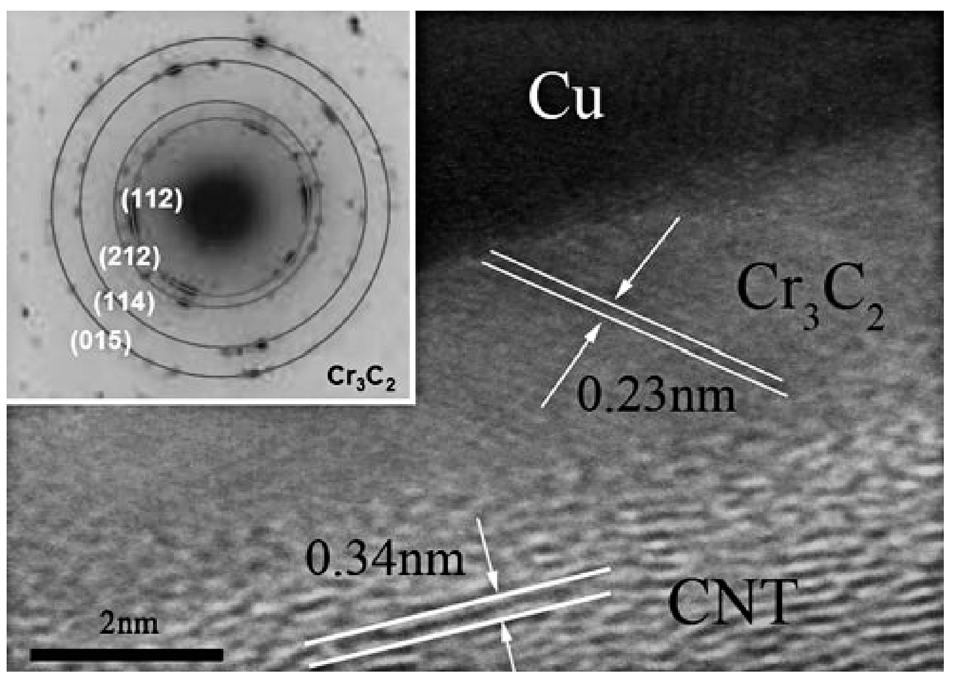
- Cho, S.; Kikuchi, K.; Kawasaki, A.; Kwon, H.; Kim, Y. Effective load transfer by a chromium carbide nanostructure in a multi-walled carbon nanotube/copper matrix composite. Nanotechnology 2012, 23, 315705. [Google Scholar] [CrossRef] [PubMed]
- Chu, K.; Jia, C.; Li, W.; Wang, P. Mechanical and electrical properties of carbon-nanotube-reinforced Cu–Ti alloy matrix composites. Phys. Status Solidi Appl. Res. 2013, 210, 594–599. [Google Scholar] [CrossRef]
- Lin, D.; Liu, C.R.; Cheng, G.J. Laser sintering of separated and uniformly distributed multiwall carbon nanotubes integrated iron nanocomposites. J. Appl. Phys. 2014, 115, 113513. [Google Scholar] [CrossRef]
- Bakshi, S.R.; Agarwal, A. An analysis of the factors affecting strengthening in carbon nanotube reinforced aluminum composites. Carbon 2011, 49, 533–544. [Google Scholar] [CrossRef]
- Abdizadeh, H.; Ebrahimifard, R.; Baghchesara, M.A. Investigation of microstructure and mechanical properties of nano MgO reinforced Al composites manufactured by stir casting and powder metallurgy methods: A comparative study. Compos. Part B Eng. 2014, 56, 217–221. [Google Scholar] [CrossRef]
- Coleman, J.N.; Cadek, M.; Blake, R.; Nicolosi, V.; Ryan, K.P.; Belton, C.; Fonseca, A.; Nagy, J.B.; Gun’ko, Y.K.; Blau, W.J. High performance nanotube-reinforced plastics: Understanding the mechanism of strength increase. Adv. Funct. Mater. 2004, 14, 791–798. [Google Scholar] [CrossRef]
- Zhou, W.; Yamamoto, G.; Fan, Y.; Kwon, H.; Hashida, T.; Kawasaki, A. In-situ characterization of interfacial shear strength in multi-walled carbon nanotube reinforced aluminum matrix composites. Carbon 2016, 106, 37–47. [Google Scholar] [CrossRef]
- Nozaka, Y.; Wang, W.; Shirasu, K.; Yamamoto, G.; Hashida, T. Inclined slit-based pullout method for determining interfacial strength of multi-walled carbon nanotube–alumina composites. Carbon 2014, 78, 439–445. [Google Scholar] [CrossRef]
- Tsuda, T.; Ogasawara, T.; Deng, F.; Takeda, N. Direct measurements of interfacial shear strength of multi-walled carbon nanotube/PEEK composite using a nano-pullout method. Compos. Sci. Technol. 2011, 71, 1295–1300. [Google Scholar] [CrossRef]
- Kwon, H.; Kawasaki, A. Extrusion of spark plasma sintered aluminum-carbon nanotube composites at various sintering temperatures. J. Nanosci. Nanotechnol. 2009, 9, 6542–6548. [Google Scholar] [CrossRef] [PubMed]
- Kwon, H.; Takamichi, M.; Kawasaki, A.; Leparoux, M. Investigation of the interfacial phases formed between carbon nanotubes and aluminum in a bulk material. Mater. Chem. Phys. 2013, 138, 787–793. [Google Scholar] [CrossRef]
- Ruehle, M.; Evans, A.G. Structure and chemistry of metal/ceramic interfaces. Mater. Sci. Eng. A 1989, 107, 187–197. [Google Scholar] [CrossRef]
- Deng, C.; Wang, D.; Zhang, X.; Li, A. Processing and properties of carbon nanotubes reinforced aluminum composites. Mater. Sci. Eng. A 2007, 444, 138–145. [Google Scholar] [CrossRef]
- Li, H.; Kang, J.; He, C.; Zhao, N.; Liang, C.; Li, B. Mechanical properties and interfacial analysis of aluminum matrix composites reinforced by carbon nanotubes with diverse structures. Mater. Sci. Eng. A 2013, 577, 120–124. [Google Scholar] [CrossRef]
- Liu, Z.; Xiao, B.; Wang, W.; Ma, Z. Developing high-performance aluminum matrix composites with directionally aligned carbon nanotubes by combining friction stir processing and subsequent rolling. Carbon 2013, 62, 35–42. [Google Scholar] [CrossRef]
- Zhou, W.; Yamaguchi, T.; Kikuchi, K.; Nomura, N.; Kawasaki, A. Effectively enhanced load transfer by interfacial reactions in multi-walled carbon nanotube reinforced Al matrix composites. Acta Mater. 2017, 125, 369–376. [Google Scholar] [CrossRef]
- Sule, R.; Olubambi, P.; Sigalas, I.; Asante, J.; Garrett, J.; Roos, W. Spark plasma sintering of sub-micron copper reinforced with ruthenium–carbon nanotube composites for thermal management applications. Synth. Met. 2015, 202, 123–132. [Google Scholar] [CrossRef]
- Cho, S.; Kikuchi, K.; Miyazaki, T.; Kawasaki, A.; Arami, Y.; Silvain, J.F. Epitaxial growth of chromium carbide nanostructures on multiwalled carbon nanotubes (MWCNTs) in MWCNT–copper composites. Acta Mater. 2013, 61, 708–716. [Google Scholar] [CrossRef]
- Kathrein, H.; Gonska, H.; Freund, F. Subsurface segregation and diffusion of carbon in magnesium oxide. Appl. Phys. A 1983, 30, 33–41. [Google Scholar] [CrossRef]
- Guo, B.; Ni, S.; Yi, J.; Shen, R.; Tang, Z.; Du, Y.; Song, M. Microstructures and mechanical properties of carbon nanotubes reinforced pure aluminum composites synthesized by spark plasma sintering and hot rolling. Mater. Sci. Eng. A 2017, 698, 292–298. [Google Scholar] [CrossRef]
- Chen, B.; Li, S.; Imai, H.; Jia, L.; Umeda, J.; Takahashi, M.; Kondoh, K. Carbon nanotube induced microstructural characteristics in powder metallurgy Al matrix composites and their effects on mechanical and conductive properties. J. Alloys Compd. 2015, 651, 608–615. [Google Scholar] [CrossRef]
- Suárez, S.; Ramos-Moore, E.; Lechthaler, B.; Mücklich, F. Grain growth analysis of multiwalled carbon nanotube-reinforced bulk Ni composites. Carbon 2014, 70, 173–178. [Google Scholar] [CrossRef]
- Chen, B.; Shen, J.; Ye, X.; Jia, L.; Li, S.; Umeda, J.; Takahashi, M.; Kondoh, K. Length Effect of Carbon Nanotubes on the Strengthening Mechanisms in Metal Matrix Composites. Acta Mater. 2017, 140, 317–325. [Google Scholar] [CrossRef]
- Hassanzadeh-Aghdam, M.; Mahmoodi, M. A comprehensive analysis of mechanical characteristics of carbon nanotube-metal matrix nanocomposites. Mater. Sci. Eng. A 2017, 701, 34–44. [Google Scholar] [CrossRef]


| Dispersion Method | Principles | Advantages | Disadvantages | Studied Metallic Systems |
|---|---|---|---|---|
| Ball milling | In this method, CNTs and metallic powders are milled in a container with hard balls. |
|
| Al [39], Ni [40], Mg [12], Cu [41], Fe [42], and their alloys |
| Ultrasonication | In this method, CNTs are dispersed in a solution composed of organic solvents or aqueous surfactant by using high frequency sound waves. |
|
| Al [14], Cu [43], Fe [44] and their alloys |
| Surfactants | In this method, non-covalent surfactants are embedded on CNTs surfaces with the aim to decrease the CNTs affinity to stick together. |
|
| Al [45], Ti [18], Ni [46], and their alloys such as CuZr and CuZrAl [47] |
| Metallization (i.e., decoration with metals) | In this method, CNTs are coated with a metallic layer such as Cu, Ni, Co, Mo, and W before their introduction into the matrix. |
|
| Al [16] and Cu [48] |
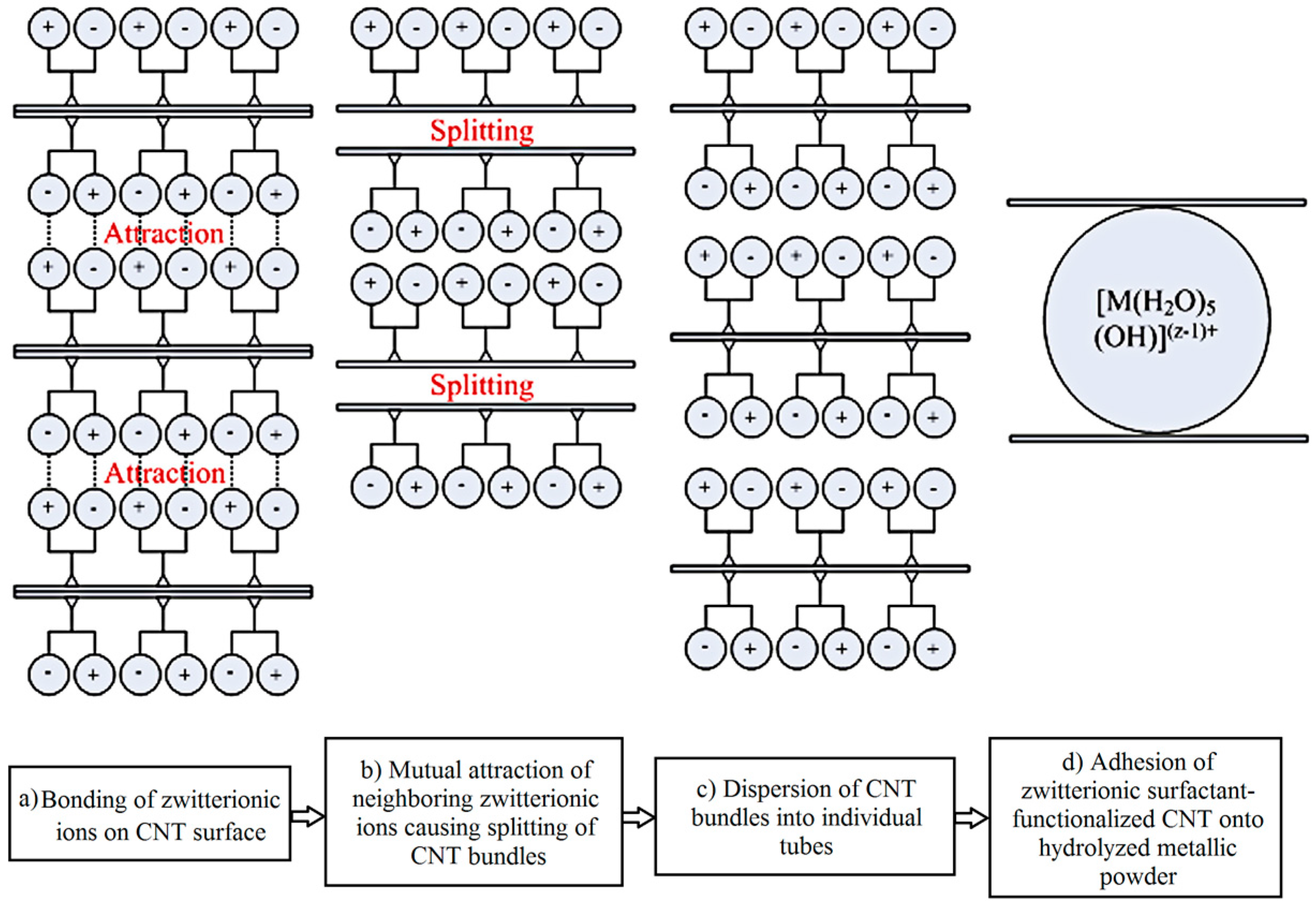
| Hetero-agglomeration principle | In this method, oppositely charged CNTs and metallic powder are co-deposited. CNTs and metallic powders are charged through a chemical step such as ultrasonication in acidic media. |
|
| Al [17] |
| Molecular level dispersion | A chemical or physical reaction occurs between functionalized CNTs and metallic ions in a solution medium. |
|
| Cu [49,50], Ag [51], Ni [52], AgPd [53], Al [54], and AlCu [55] |
| In-situ chemical synthesis | In this method, CNTs are directly synthesized from the vapor phase on the metallic powders. |
|
| Mg [56], FeCr [57], Cu [58], AlCu [59], Al [60], and Fe [61] |
| Electroless deposition | In this method, CNTs are immersed in an electrolyte solution containing metal ions. During the process, the nanotubes are covered by ions through developing potential. A substrate can be used on which CNTs and metallic ions are simultaneously deposited. |
|
| Cu [62], Ni [63], Al [64], Au, and Pt [65] |
| Electrodeposition | In this method, CNTs are embedded in an electrochemically formed metallic film. This film is deposited as metallic ions transfer from cathode or electrolyte solution to the anode. |
|
| Ni [66], Cu [67], Sn-Bi [68], Cu-Ni [69], and Ni-Co [70] |
| Using hybrid reinforcements | In this method, CNTs are added to other components such as SiC, A2O3, and graphite for better distribution. The ball milling is the most conventional method for mixing the hybrid reinforcements. |
|
| Al [71], Cu [72], Mg [73] |
| Preform infiltration | In this method, an initial preform of CNTs and other components is fabricated, and the molten metal is infiltrated into it. |
|
| Al [74,75] |
| FSP/SLM induced dispersion | After the fabrication of bulk CNT/metal nanocomposites, friction stir processing (FSP) or selective laser melting (SLM) is used for re-dispersing CNTs. |
|
| Al [76], Cu [77] |
| Induction melting-based dispersion | In this method, a solid metal with a CNT-containing flux is poured into an induction furnace. The presence of such a flux decreases the melting temperature of the solid metal. Finally, CNTs are dispersed by induction-formed fluctuations. |
|
| Al [78], Ti [79] |
| Casting-based methods such as stir casting and squeeze casting | In these methods, CNTs are dispersed in a molten metal through stirring or squeezing. |
|
| Al [80] |
| Fabrication Process | Processing Temperature (°C) | Applied Pressure (MPa) | Processing Duration (min) | Final Phase Structure | Reported Mechanisms for Structural Changes | Reported Changes in Properties Due to CNTs Structural Changes | Ref. |
|---|---|---|---|---|---|---|---|
| Spark plasma sintering | 1500 | 80 | 20 | diamond | Not reported | Not reported | [105] |
| Spark plasma sintering | 1500 | 80 | 20 | diamond + graphite | Not reported | Not reported | [113] |
| Spark plasma sintering + polishing | 1600 | 60 | 1 | graphene | Shear stress induced by polishing which leads to peeling graphene away from CNTs | A significant reduction in friction coefficient due to the much lower friction between formed graphene layers | [106] |
| Spark plasma sintering | 1000, 1500, 2000 | 50 | 5 | graphene | Not reported | Enhanced thermal stability due to the formation of graphene at a high sintering temperature | [114] |
| Annealing heat treatment |
| - | 30 |
| Not reported | Not reported | [116] |
| Spark plasma sintering | 1500 | 80 | 20 |
| High localized temperatures arisen from the presence of plasma during the sintering as a prerequisite for the formation of diamond | Not reported | [122] |
| Spark plasma sintering | 1700, 1800, 1900, 2000 | 100 | 5 |
| The formation of graphene nanosheets due to the evaporation of carbon atoms during the heating stage of SPS and their agglomeration during the cooling stage | An increment in electrical conductivity due to the formation of graphene nanosheets | [123] |
| Spark plasma sintering + Fe35Ni catalysts | 1200 | 70 | 20 | diamond + graphite | The formation of diamond through a layer-by-layer mechanism | Not reported | [124] |
| Chemical vapor deposition | 700 | - | 30 | graphite | Not reported | Not reported | [107] |
| Chemical vapor deposition | 700 | - | 56 | amorphous carbon | Not reported | Not reported | [108] |
| Compaction + laser beam heating | 2226 | 17,000 | - | diamond | Direct conversion of CNTs to nano-sized diamonds with no an intermediate step such as melting or dissolution | Not reported | [125] |
| Annealing at high pressure | 1300 | 4500 | 12 | diamond | The conversion of CNTs to quasi-spherical onion-like structures followed by the formation of diamond crystals | Not reported | [117] |
| Chemical vapor deposition | 500 | - | 2160 | highly ordered graphite | CNT → carbon nanofiber → highly ordered graphite | Not reported | [119] |
| Electrical breakdown method | - | - | - | graphene nanoribbon | Fast unwrapping of MWNTs with no an intermediate step | Not reported | [126] |
| Hydrogen plasma | 726 | - | - | diamond | The formation and growth of diamond particles due to the formation of amorphous carbon clusters with sp3 bonds | Not reported | [115] |
| Solution-based oxidative process | 55–70 | - | 60 | graphene nanoribbons + graphite oxide | The formation of graphene nanoribbons due to complete unravelling of CNT side walls | Not reported | [109] |
| High temperature annealing heat treatment | 1100–2000 | - | 240 min heating + 480 min cooling process | graphite nanoribbons | The thermal activation of three different mechanisms for different heat treatment temperatures:
| Not reported | [118] |
| High pressure and high temperature heat treatment | 1600–2000 | 15,000 | 10–10,000 s (Exact dwelling time has not been reported) | diamond | The formation of diamond phase as a result of atomic diffusion with no graphitization or formation of intermediate phases | Not reported | [127] |
| Amount of Added CNTs | Fabrication Method | Increase in Tensile Strength Value (%) | Ref. |
|---|---|---|---|
| 2 wt % MWNTs | Sintering → hot extrusion | 57.5 | [139] |
| 5 vol % MWNTs | SPS → hot extrusion | 128 | [120] |
| 5 wt % MWNTs | Sintering → pressing → annealing | 184 | [128] |
| Fabrication Method | CNTs Volume Fraction | Type of Used CNTs | Chemical Composition of the Formed Intermetallics | Variations of Mechanical Properties | Suggested Reasons for Enhanced/Deteriorated Properties | Ref. |
|---|---|---|---|---|---|---|
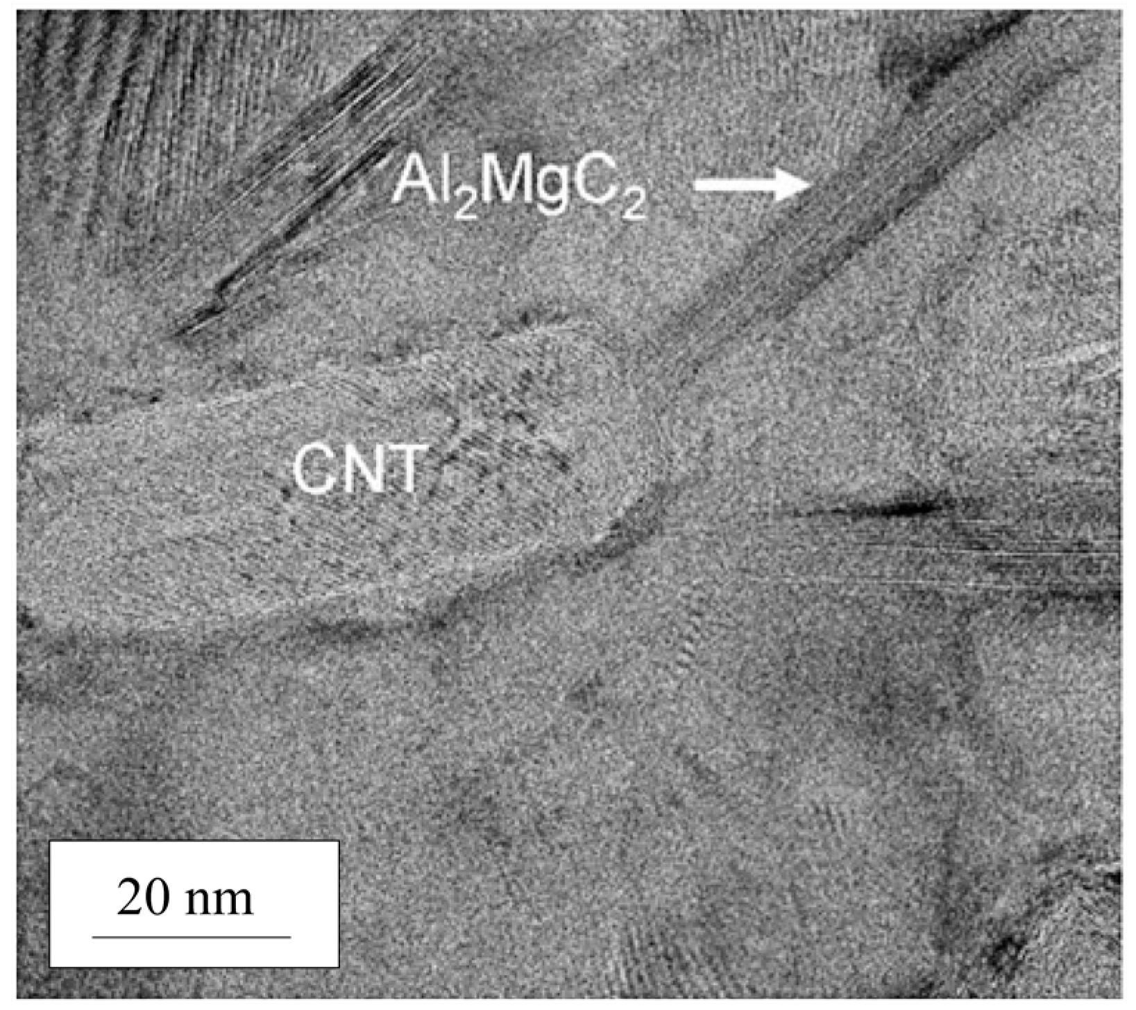
| Powder metallurgy based wet processing | 0.71–1.56 vol % MWNTs | Functionalized; using a zwitterionic surfactant | Al2MgC2 |
|
| [144] |
| Powder metallurgy technique | 0.3 wt % MWNTs | Ni-coated | Mg2Ni |
|
| [12] |
| DMD (disintegrated melt deposition) technique followed by hot extrusion | 1.5 vol % CNT nanoparticles | Unfunctionalized | Al4C3, Al12Mg17, Al3Mg2 |
|
| [19] |
| Squeeze infiltration method | 1–5 wt % MWNTs | Acid treated | SiC |
|
| [145] |
| DMD method followed by hot extrusion | 1.0 vol % | Acid treated | Mg17Al12 |
|
| [148] |
| Powder metallurgy method | 0.25–1.0 wt % MWNTs | Unfunctionalized | Mg17Al12 |
|
| [146] |
| Accumulative roll bonding | 3 vol % MWNTs | Unfunctionalized | Al3Mg2, Mg17Al12 | - |
| [147] |
© 2017 by the authors. Licensee MDPI, Basel, Switzerland. This article is an open access article distributed under the terms and conditions of the Creative Commons Attribution (CC BY) license (http://creativecommons.org/licenses/by/4.0/).
Share and Cite
Azarniya, A.; Safavi, M.S.; Sovizi, S.; Azarniya, A.; Chen, B.; Madaah Hosseini, H.R.; Ramakrishna, S. Metallurgical Challenges in Carbon Nanotube-Reinforced Metal Matrix Nanocomposites. Metals 2017, 7, 384. https://doi.org/10.3390/met7100384
Azarniya A, Safavi MS, Sovizi S, Azarniya A, Chen B, Madaah Hosseini HR, Ramakrishna S. Metallurgical Challenges in Carbon Nanotube-Reinforced Metal Matrix Nanocomposites. Metals. 2017; 7(10):384. https://doi.org/10.3390/met7100384
Chicago/Turabian StyleAzarniya, Abolfazl, Mir Saman Safavi, Saeed Sovizi, Amir Azarniya, Biao Chen, Hamid Reza Madaah Hosseini, and Seeram Ramakrishna. 2017. "Metallurgical Challenges in Carbon Nanotube-Reinforced Metal Matrix Nanocomposites" Metals 7, no. 10: 384. https://doi.org/10.3390/met7100384