Evaluation of Tool Path Strategy and Cooling Condition Effects on the Cutting Force and Surface Quality in Micromilling Operations


1
Department of Mechanical Engineering, Karamanoglu Mehmetbey University, Karaman 70100, Turkey
2
Department of Mechanical Engineering, Mehmet Akif Ersoy University, Burdur 15030, Turkey
*
Author to whom correspondence should be addressed.
Metals 2017, 7(10), 426; https://doi.org/10.3390/met7100426
Submission received: 22 August 2017
/
Revised: 15 September 2017
/
Accepted: 9 October 2017
/
Published: 13 October 2017
(This article belongs to the Special Issue Metals Machining – Recent Advances in Experimental and Modeling of the Cutting Process)
Abstract
:Compared to milling on a macro scale, the micromilling process has several cumbersome points that need to be addressed. Rapid tool wear and fracture, severe burr formation, and poor surface quality are the major problems encountered in the micromilling process. This study aimed to reveal the effect of cutting path strategies on the cutting force and surface quality in the micromilling of a pocket. The hatch zigzag tool path strategy and the contour climb tool path strategy under different cooling conditions (e.g., dry, air blow, and flood coolant) at fixed cutting parameters. The micromilling tests revealed that better results were obtained with the use of the contour tool path strategy in terms of cutting forces (by up to ~43% compared to the dry condition) and surface quality (by up to ~44% compared to the air blow condition) when compared to the hatch tool path strategy. In addition, the flood coolant reduces the cutting temperature and eliminates chips to significantly enhance the quality of the micro milled surface.
1. Introduction
In the current era of manufacturing, there is a great demand for micro-scale devices and components which have complex features and are manufactured from many different materials [1]. Micro-scale parts are utilized in a variety of fields, including the aerospace, automotive, medical, and precision die and mold manufacturing industries [2]. Micro machining is defined as the process of machining miniature parts using micro cutting tools. This process is capable of creating 3D free-form elements and thus, is used in a wide range of engineering applications for the production of micro-components [3]. A number of studies have evaluated the performance of macro cutting tools in conventional machining by examining parameters such as the surface roughness, cutting force, tool wear, tool life, shape and dimensional errors, and computer aided manufacturing (CAM) stage in the high-speed milling of complex surfaces and parts [4,5,6,7,8,9,10,11]. The manufacturing of components from various materials via micro machining is, as yet, a more complex process than conventional machining. Difficulties encountered by researchers in this direction include an unpredictable tool life, burr formation, and poor surface quality. The high cutting force and temperature that occur during micro machining lead to problems such as sudden damage to the micro-tools.
Much research has been carried out in recent years to improve the machinability of various materials used with micro-cutting tools. Most of these studies have focused on slot and channel operations [12,13,14,15]. Nevertheless, very few researches have been dedicated to pocket milling, profile milling, and the machining of different geometries with micro cutting tools. Zariatin et al. [14] successfully carried out the micromilling of aluminum alloy 1100 thin-walled features with a minimum thickness of 11.71 μm. Thepsonthi and Özel [16] presented a method for optimizing process parameters and determining the best tool path while conforming to the constraints of micro machining in the micro end milling of a circular thin-walled rib feature. They reported optimization results showing significant improvements in the process performance, including decreased burr formation and increased tool life and surface quality. Oliaei and Karpat [17] examined the correlation between micro end mill tool wear patterns and machining parameters by machining a 15-mm diameter circular pocket using six spiral tool paths under varying experimental conditions. The advantages and disadvantages of different micromilling machining strategies were investigated and validated experimentally by Dimov et al. [18]. In addition, they proposed a way to store and re-use professional micro machining strategies covering a variety of feature types. The research of Kiswanto et al. [19] produced an experimental guide for the fabrication of micro impellers via the micromilling process. Their study provided detailed guidelines for the micromilling process relating to micro-products in terms of design feasibility and constraints, machining strategy planning using a commercial CAD/CAM system, and the selection of cutting parameters.
In an innovative lab-on-a-chip (biochip) established by the micro manufacturing technique, micro-fluidic channels were directly machined via micro end milling [20]. The powder blasting process was then used to remove the micro burrs that predictably formed at the channel edges. The results showed that the injection molding of microfluidic biochips could be successfully achieved using a combination of micro end milling and powder blasting. In their study, Katahira et al. [21] used a polycrystalline diamond micromilling tool to investigate the machining properties of high-purity SiC. The results revealed that it was possible to obtain a high-quality surface roughness average Ra = 1.7 nm if the removed chips were sufficiently thin to carry out ductile mode machining. The micro end milling process planning proposed by Özel and Liu [22] for the machining of micro mold cavities utilized a time-domain simulation model. The model featured predictive capacity for practical micro machining performance parameters including cutting force, surface form, and surface roughness. Perçin et al. [23] conducted experimental investigations and reported the effects of different machining conditions and cutting parameters on thrust force, torque, tool wear, burr formation, and surface roughness for the micro drilling of a Ti-6Al-4V alloy. In the micromilling of the same alloy, a hybrid system for cooling and lubrication which was mixed oil with chilled air was designed and its effect on cutting performance was examined in terms of tool wear and burr formation. According to the findings, the use of the hybrid system resulted in minimum tool wear and burr size [24].
In contrast to the existing literature, this study aimed to investigate the effects of the cutting tool path strategy and cooling conditions on the cutting force and surface roughness of the AA 5083 H116 micro-milling of pocket geometry.
2. Materials and Methods
Micro-milling experiments were performed on a three-axis milling machine (Quaser MV154C, Quaser Machine Tools Inc., Taichung, Taiwan). During the milling operation, the cutting forces were measured with the help of a Kistler 9257B dynamometer (Kistler, Winterthur, Switzerland). After the micro cutting tests, the surface area roughness (Sa), root mean square roughness (Sq), and three-dimensional (3D) view of the micro-milled pocket were measured using an optical profilometer (Zygo ZEGAGE, Zygo corporation, Middlefield, CT, USA). The micromilling experimental setup is shown in Figure 1. The samples used in this study were prepared from AA 5083 H116 blocks of 95 mm × 75 mm × 5 mm. The chemical composition and mechanical properties of the AA 5083 H116 aluminum alloy are shown in Table 1 [25]. Micro-pocket milling experiments were carried out under three different cooling conditions: dry, air-blow, and flood coolant. The air-blow and flood coolant were delivered to the machining area through a nozzle. Moreover, the air-blow cooling was carried out without the addition of oil. The air pressure used in the micro milling experiments with an air blow was less than 3 bars. Water-soluble oil was used as the flood coolant with a concentration of 10%. Characteristics of the flood coolant used in the experiments are: density (15 °C, g/mL) 0.88, kinematic viscosity (40 °C, mm2/s) 25, and emulsion (pH, 20 °C) 8.9. Flood coolant was used at low pressure (≤2 bar) and flow rate (0.20 L/min) during cutting so as to ensure that the cutting tool did not fail, the chips did not stick to the cutting tool, and the measurement results were not adversely affected. The experimental cutting parameters for the micromilling of the AA 5083 H116 alloy were the spindle speed, feed rate, axial depth of cut, and radial depth of cut, which were fixed at 9000 rpm, 2 μm/tooth, 0.15 mm, and 0.25 mm, respectively. Each micromilling test was repeated three times to ensure the reproducibility of the results.
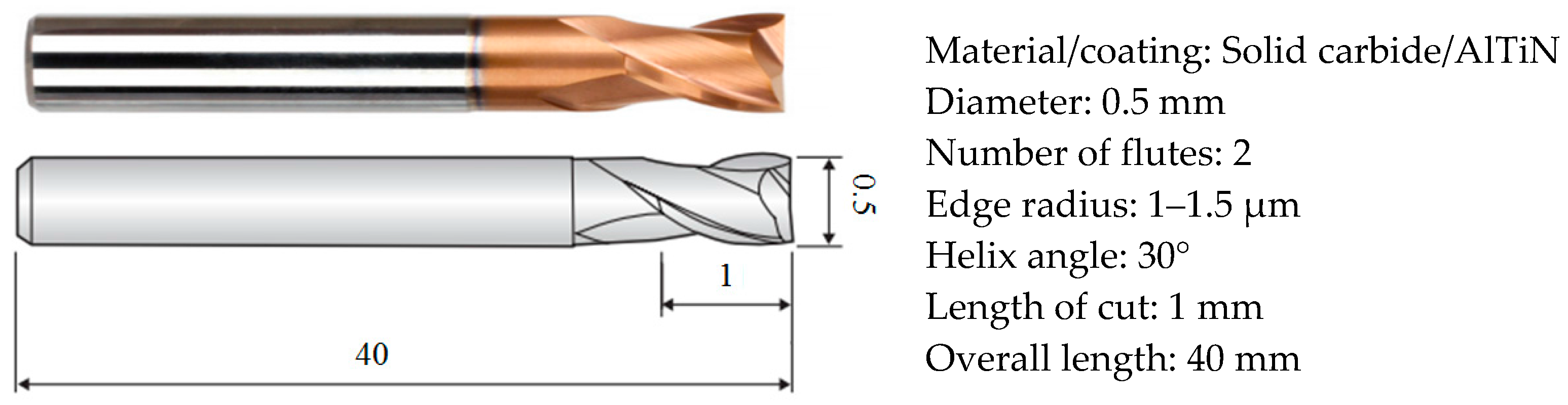
An aluminum titanium nitride-coated carbide micro end-mill with two teeth was used to create the micro-pockets in a one-pass operation. The geometric characteristics and related information on the micro end mill (Widin ZE702005, Widin US, Changwon-Si, Gyeongnam, Korea) used in the experiments are given in Figure 2. A new micro-tool was used in the pocket milling for each new tool path and cooling condition.
Two different pocket milling cutter path strategies were used in the micromilling experiments: the hatch zigzag and the contour climb. The 3 mm × 3 mm-dimension square geometry was milled using two different cutting tool path strategies, with a 0.5-mm diameter cutting tool and three different coolant factors. The SolidCam commercial software (2014, SolidCAM Inc., Newtown, PA, USA) was used for the generation of the three-axis tool paths. The two different cutter path strategies in the pocket milling produced by the software are shown in Figure 3. The same cutting parameters were used in the machining of both pockets, and for both strategies, a 50% tool diameter overlap was employed.
The pocket machining operation with micro cutting tools using the hatch tool path strategy took 50.5 s, while the contour tool path strategy took 52.6 s. There are 24 steps within the hatch zigzag strategy, whereas the contour climb strategy has 36 steps. The contour climb strategy had 50% more steps than the hatch zigzag strategy. The total traveling length of the micro cutting tool generated by the hatch tool path strategy (28.856 mm) was shorter than that generated by the contour tool path strategy (31.255 mm). Moreover, in the micro milling operation performed with the contour tool path strategy, cutting tools were not in contact with long-continued material as long as the hatch tool path strategy. It is also easier to evacuate chips because of the removal of chips with short cycles.
3. Results and Discussions
The micromilling of the AA 5083 H116 alloy under dry, air blow, and flood coolant conditions was performed successfully using two different cutter path strategies at a constant cutting speed, feed rate, and depth of cut. Cutting forces during the machining of the AA 5083 H116 alloy with different cutting tool path strategies and different cooling conditions using micro cutting tools were measured in the directions of x, y, and z via a Kistler force dynamometer (Kistler, Winterthur, Switzerland). The forces measured in the x and y directions with respect to cutting time are shown in Figure 4. The cutting forces in a machining process using micro-tools are significantly lower when compared with those of machining performed with macro-sized cutting tools. With the contour tool path strategy, the cutting force was lower in the pocket machining operation than with the hatch tool path strategy. In the current study, the amount of chip/material (uncut volume) processed by the selected geometry via the micro cutting tool (Widin US, Changwon-Si, Gyeongnam, Korea) was 1.275 mm3. This volume of the chip was machined with 24 steps in 50.5 s by using the hatch tool path strategy and with 36 steps in 52.6 s by using the contour tool path strategy. If the final contour could not be made in the hatch tool path strategy, a shorter tool path was taken according to the contour tool path strategy and thus, the tool path length was shorter [26]. Milling the same volume of material with the contour tool path strategy took 2.1 s 12 steps longer than the hatch tool path strategy. Since in the contour tool path strategy, increases of 4.15% of the machining time and 50% also optimized the amount of chip removed, it was thought to cause the cutting forces at the time of machining to be lower than with the hatch tool path strategy.
In both tool path strategies, as expected, lower cutting forces occurred under flood coolant conditions, while the maximum forces occurred under dry cutting. The reason for the higher cutting force in the micro machining performed under dry conditions was the adhesion of the workpiece to the cutting tool during cutting and the high amount of friction at the tool-chip interface. This huge friction created more heat, thus causing the material to adhere more to the cutting tool [27]. In the micromilling tests made under air blow cooling, the cutting forces were lower than those for dry cutting, and higher than those under flood coolant conditions, as the air blow did not cool the workpiece as effectively as the flood coolant. The reason that the cutting forces under flood conditions were minimum is that the adherence of the workpiece to the cutting tool was minimum, thus producing a lower friction force during machining [28]. During the cutting time, the machining length and cutting force effects of different cooling methods such as minimum quantity lubrication (MQL), liquid nitrogen (LN2), carbon dioxide (CO2), MQL + LN2, and MQL + CO2 have been investigated in detail. The use of MQL, LN2, and CO2 increased the machining length according to dry cutting conditions. MQL + LN2 and MQL + CO2 also gave the best results. The cutting forces generated during machining were compared; it has been stated that there is a little too much force during dry cutting compared to other cooling methods [29].
In industrial applications, surface finish is a crucial factor that affects the quality and performance of mechanical parts, as well as production costs [30]. Much research is being done on minimizing flaws in the surface finish by machining various engineering materials with different cutting combinations. The present study used the hatch and the contour tool path strategies under different cooling conditions in the micro pocket milling of the AA 5083 H116 alloy by using a micro cutting tool. A 1.5 × 1.5 mm2 section of the machined pocket surface was scrutinized and scanned using an optical profilometer (Zygo Corporation, Middlefield, CT, USA) with a 5.5× magnification lens, and 3D surface topography and surface area roughness measurements were taken (Figure 5). Surface measurement is a common term which encompasses more specific types of measurements such as surface shape, surface finish, surface profile roughness (Ra), or in surface area roughness (Sa), surface texture, and structural characterization [31]. In the surface profile roughness measurement, measurements are taken along a line from the machined surface, while surface area roughness measures the area where the microscope is seen. Surface profile roughness provides very small scale information, while the surface area roughness provides more information about the surface being studied.
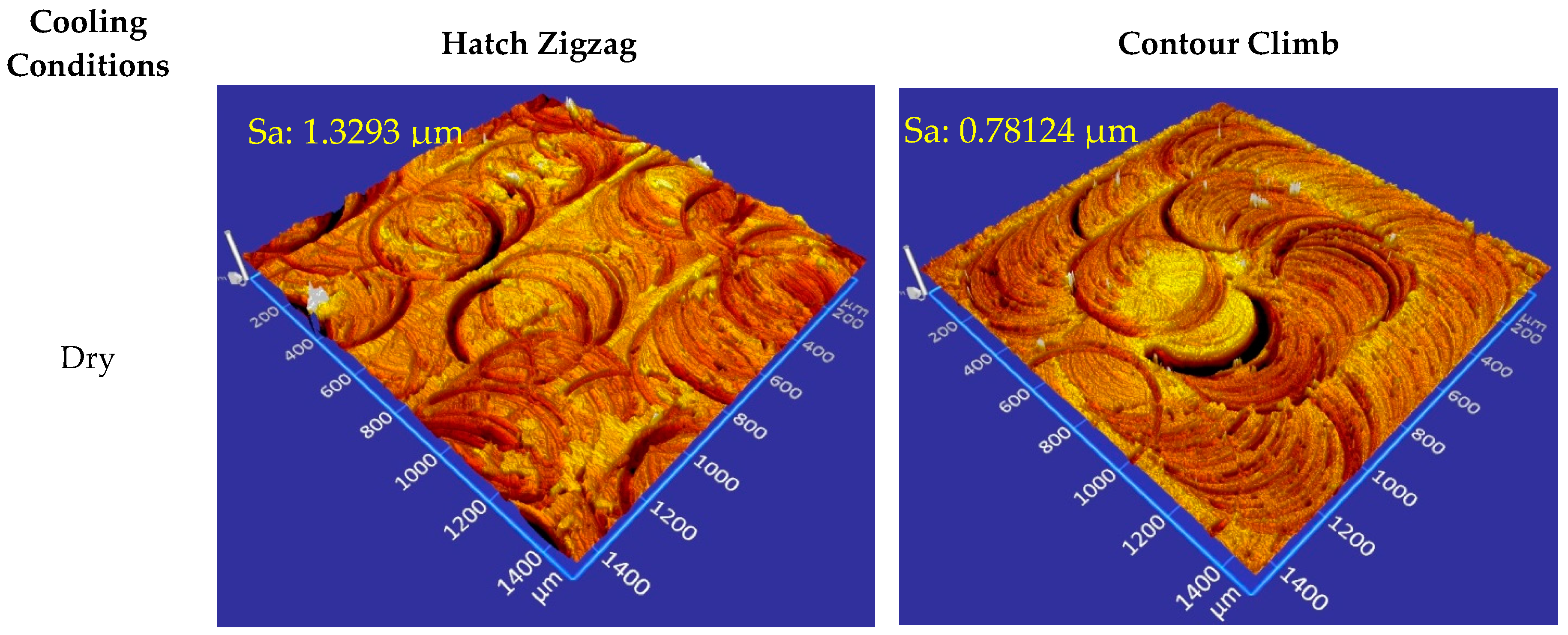
Figure 6 shows the comparisons of the 3D surface topography of the pockets milled using the hatch and the contour tool path strategies under different cooling conditions—dry, air blow, and flood coolant—at fixed cutting conditions. It was clearly shown that a higher quality surface was obtained in the micro machining operation carried out with the contour tool path strategy when compared to the one obtained with the hatch tool path strategy, in general. The zigzag movement of the cutting tool in the hatch tool path strategy causes the cutting tool to cut alternately along the spindle direction and then against it, generating, respectively, conventional and climb milling. This change in the cutting mode causes the formation of a non-uniform surface quality. Commonly, the efficient cutting occurs in the reverse direction of offsetting in the contour tool path strategy, i.e., from the inside toward the outside. This gives well stability to the work material because the cutting motion starts near the work material centre [26].
In both tool path strategies, a track of the cutting tool was evident on the machined workpiece. Nevertheless, under the flood coolant cutting conditions, these tool traces were minimized compared to results under the dry and air blow conditions. In addition, in both tool path strategies, the surfaces were better with the flood and air blow cooling compared to dry cutting. The lowest cutting force was obtained under flood cooling conditions, in both tool path strategies, (Figure 4). Due to the reduction in cutting force, the flood coolant resulted in a better surface quality, as can be seen in Figure 6. The use of the flood cooling during cutting provided better lubrication and cooling effects, resulting in lower friction at the tool-chip interface. Due to the reduction in cutting temperature and friction, there was less material adhesion to the tool, which increased the quality of the surface being machined. The main reason for obtaining a rougher surface under dry cutting compared to the other cooling methods was the higher temperature and friction at the tool-chip-workpiece interface.
The surface area roughness (Sa) and root mean square roughness (Sq) values of the surfaces obtained from the 3D surface topographies are presented in Figure 6 and quantified in Figure 7. Both the surface area roughness and root mean square roughness values are lower in the contour tool path strategy than the hatch tool path strategy—except under flood coolant conditions. The results are consistent with the research that has been carried out in previous studies [22]. The best surface quality was obtained under flood cooling conditions in both tool path strategies, while the worst surface quality was obtained by the hatch tool path strategy under dry cutting conditions. Aramcharoen and Mativenga [32] modeled the energy demands of the machine in order to evaluate different tool paths—zigzag x- and y-axis, zigzag x-axis, contour, and spiral—and as a conclusion of the comparison, emphasized that the contour tool path strategy was the most efficient and resulted in the best surface quality.
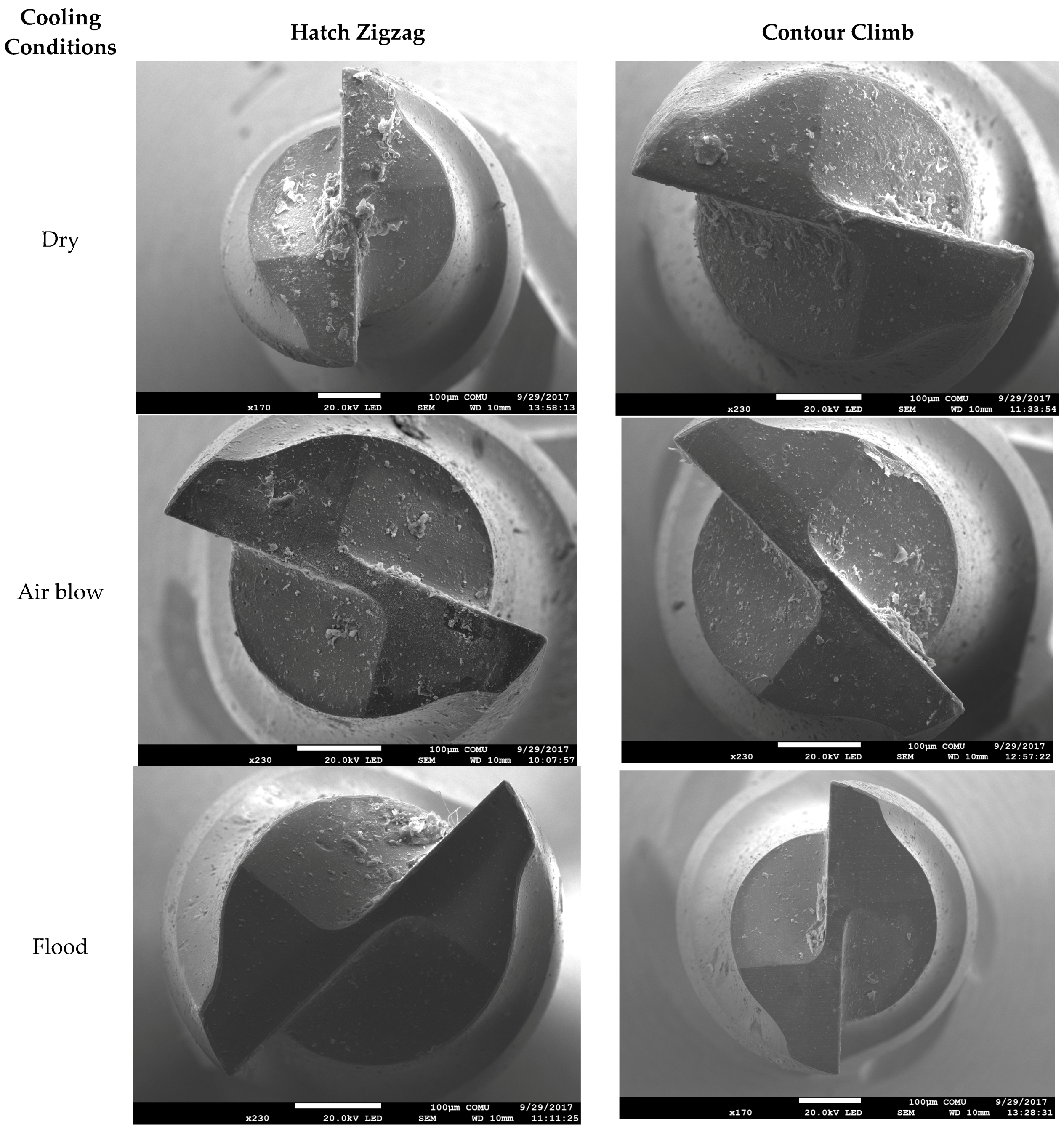
The wear on the cutting tool during the micromachining operation is more important, more severe, and more risky than the wear on the macromachining. With the start of tool wear and the increase in wear, the cutting forces, friction, and cutting temperature increase. After a certain limit, tool wear can cause catastrophic and abrupt failure of the tool without any caution that causes substantial damage to the work material and even to the machine tool [33]. A study on the wear of the micro milling tools was made using a scanning electron microscope (SEM). Figure 8 shows the comparisons of the tool wear using the hatch and the contour tool path strategies under different cooling conditions—dry, air blow, and flood coolant—at fixed cutting conditions. A certain amount of wear on the cutting edges of the micro end mills has also been observed during micromilling experiments. The most wear occurs in dry cutting conditions, while the least tool wear occurs in flood coolant cutting conditions. The formation of more tool wear in dry conditions is believed to be the main reason for the higher cutting forces, cutting temperature, and friction. In view of that, the milling forces increased during dry micromilling in agreement with the graphic offered in Figure 4. The deterioration in cutting edges and loss of sharpness are less than in the flood coolant conditions. In the micro milling under dry and air blow conditions, considerable chip adhesion on the cutting edge of the tool and flute is observed, while this chip adhesion under flood coolant is at a minimum level when compared with other conditions.
4. Conclusions
Micromilling of an AA 5083 H116 alloy under dry, air blow, and flood coolant conditions was performed successfully using a constant cutting speed, feed rate, and depth of cut with two different cutter path strategies.
- (1)
- Within the limitation of current research, it was concluded that the tool path strategy and coolant factor played an important role in terms of cutting force and surface quality for the micromilling of the AA 5083 H116 alloy.
- (2)
- In the case of the contour tool path strategy in micro milling tests, it takes more time (2.1 s), more steps (12 step), and a greater traveling length of the tool (2.399 mm) than the hatch tool path strategy.
- (3)
- With the contour tool path strategy, the cutting force was lower in the pocket machining operation than with the hatch tool path strategy.
- (4)
- The surface quality of the micro-milled parts was improved with the flood coolant and contour climb strategy, and at the same time, the cutting forces were reduced by this combination.
- (5)
- By using a flood coolant during machining, the micro tool marks are homogeneously formed and the deterioration in the micro machined surface is minimized.
Author Contributions
Gültekin Basmaci designed the experiments and analyzed the data; Uğur Köklü performed the experiments, analyzed the data, and wrote the paper.
Conflicts of Interest
The authors declare no conflict of interest.
References
- Filiz, S.; Conley, C.M.; Wasserman, M.B.; Ozdoganlar, O.B. An experimental investigation of micro-machinability of copper 101 using tungsten carbide micro-endmills. Int. J. Mach. Tools Manuf. 2007, 47, 1088–1100. [Google Scholar] [CrossRef]
- Hassanpour, H.; Sadeghi, M.H.; Rezaei, H.; Rasti, A. Experimental study of cutting force, microhardness, surface roughness, and burr size on micromilling of Ti6Al4V in minimum quantity lubrication. Mater. Manuf. Process. 2016, 31, 1654–1662. [Google Scholar] [CrossRef]
- Bajpai, V.; Kushwaha, A.K.; Singh, R.K. Burr formation and surface quality in high speed micro-milling of titanium alloy (Ti6Al4V). In Proceedings of the ASME 2013 International Manufacturing Science and Engineering Conference Collocated with the 41st North American Manufacturing Research Conference, Madison, WI, USA, 10–14 June 2013; pp. 17–24. [Google Scholar]
- Çiçek, A.; Kara, F.; Kivak, T.; Ekici, E.; Uygur, I. Effects of deep cryogenic treatment on the wear resistance and mechanical properties of AISI H13 hot-work tool steel. J. Mater. Eng. Perform. 2015, 24, 4431–4439. [Google Scholar] [CrossRef]
- Budak, E.; Altintas, Y. Modeling and avoidance of static form errors in peripheral milling of plates. Int. J. Mach. Tools Manuf. 1995, 35, 459–476. [Google Scholar] [CrossRef]
- Davim, J.P.; Reis, P. Damage and dimensional precision on milling carbon fiber-reinforced plastics using design experiments. J. Mater. Process. Technol. 2005, 160, 160–167. [Google Scholar] [CrossRef]
- Çiçek, A.; Kara, F.; Kivak, T.; Ekici, E. Evaluation of machinability of hardened and cryo-treated AISI H13 hot work tool steel with ceramic inserts. Int. J. Refract. Met. Hard Mater. 2013, 41, 461–469. [Google Scholar] [CrossRef]
- Özel, T.; Karpat, Y. Predictive modeling of surface roughness and tool wear in hard turning using regression and neural networks. Int. J. Mach. Tools Manuf. 2005, 45, 467–479. [Google Scholar] [CrossRef]
- Şeker, U.; Hasirci, H. Evaluation of machinability of austempered ductile irons in terms of cutting forces and surface quality. J. Mater. Process. Technol. 2006, 173, 260–268. [Google Scholar] [CrossRef]
- López de Lacalle, L.N.; Lamikiz, A.; Muñoa, J.; Sánchez, J.A. The CAM as the centre of gravity of the five-axis high speed milling of complex parts. Int. J. Prod. Res. 2005, 43, 1983–1999. [Google Scholar] [CrossRef]
- Lamikiz, A.; De Lacalle, L.L.; Sánchez, J.A.; Salgado, M.A. Cutting force integration at the CAM stage in the high-speed milling of complex surfaces. Int. J. Comput. Integr. Manuf. 2005, 18, 586–600. [Google Scholar] [CrossRef]
- Gao, Q.; Gong, Y.; Zhou, Y.; Wen, X. Experimental study of micro-milling mechanism and surface quality of a nickel-based single crystal superalloy. J. Mech. Sci. Technol. 2017, 31, 171–180. [Google Scholar] [CrossRef]
- Ucun, I.; Aslantas, K.; Bedir, F. An experimental investigation of the effect of coating material on tool wear in micro milling of Inconel 718 super alloy. Wear 2013, 300, 8–19. [Google Scholar] [CrossRef]
- Zariatin, D.L.; Kiswanto, G.; Ko, T.J. Investigation of the micro-milling process of thin-wall features of aluminum alloy 1100. Int. J. Adv. Manuf. Technol. 2017. [Google Scholar] [CrossRef]
- Jin, C.Z.; Kang, I.S.; Park, J.H.; Jang, S.H.; Kim, J.S. The characteristics of cutting forces in the micro-milling of AISI D2 steel. J. Mech. Sci. Technol. 2009, 23. [Google Scholar] [CrossRef]
- Thepsonthi, T.; Özel, T. An integrated toolpath and process parameter optimization for high-performance micro-milling process of Ti-6Al-4V titanium alloy. Int. J. Adv. Manuf. Technol. 2014, 75, 57–75. [Google Scholar] [CrossRef]
- Oliaei, S.N.B.; Karpat, Y. Influence of tool wear on machining forces and tool deflections during micro milling. Int. J. Adv. Manuf. Technol. 2016, 84, 1963–1980. [Google Scholar] [CrossRef]
- Dimov, S.; Pham, D.T.; Ivanov, A.; Popov, K.; Fansen, K. Micromilling strategies: Optimization issues. Proc. Inst. Mech. Eng. Part B J. Eng. Manuf. 2004, 218, 731–736. [Google Scholar] [CrossRef]
- Kiswanto, G.; Zariatin, D.L.; Baskoro, A.S.; Istiyanto, J. An experimental guideline to manufacture micro-impeller using micro-milling process. In Proceedings of the International Conference on Micromanufacturing, Singapore, 26–28 March 2014. [Google Scholar]
- Yun, D.J.; Seo, T.I.; Park, D.S. Fabrication of biochips with micro fluidic channels by micro end-milling and powder blasting. Sensors 2008, 8, 1308–1320. [Google Scholar] [CrossRef] [PubMed]
- Katahira, K.; Takesue, S.; Komotori, J.; Yamazaki, K. Micromilling characteristics and electrochemically assisted reconditioning of polycrystalline diamond tool surfaces for ultra-precision machining of high-purity SiC. CIRP Ann. Manuf. Technol. 2014, 63, 329–332. [Google Scholar] [CrossRef]
- Özel, T.; Liu, X. Investigations on mechanics-based process planning of micro-end milling in machining mold cavities. Mater. Manuf. Process. 2009, 24, 1274–1281. [Google Scholar] [CrossRef]
- Percin, M.; Aslantas, K.; Ucun, I.; Kaynak, Y.; Cicek, A. Micro-drilling of Ti-6Al-4V alloy: The effects of cooling/lubricating. Precis. Eng. 2016, 45, 450–462. [Google Scholar] [CrossRef]
- Aslantas, K.; Çicek, A.; Ucun, İ.; Percin, M.; Hopa, H.E. Performance evaluation of a hybrid cooling-lubrication system in micro-milling of Ti6Al4V alloy. Procedia CIRP 2016, 46, 492–495. [Google Scholar] [CrossRef]
- ASM Aerospace Specification Metals Inc. Available online: http://asm.matweb.com/search/SpecificMaterial.asp?bassnum=MA5083H116 (accessed on 20 August 2017).
- Hatna, A.; Grieve, R.J.; Broomhead, P. Automatic CNC milling of pockets: Geometric and technological issues. Comput. Integr. Manuf. Syst. 1998, 11, 309–330. [Google Scholar] [CrossRef]
- Rahim, E.A.; Sasahara, H. A study of the effect of palm oil as MQL lubricant on high speed drilling of titanium alloys. Tribol. Int. 2011, 44, 309–317. [Google Scholar] [CrossRef]
- Sreejith, P.S. Machining of 6061 aluminium alloy with MQL, dry and flooded lubricant conditions. Mater. Lett. 2008, 62, 276–278. [Google Scholar] [CrossRef]
- Pereira, O.; Rodríguez, A.; Fernández-Abia, A.I.; Barreiro, J.; de Lacalle, L.L. Cryogenic and minimum quantity lubrication for an eco-efficiency turning of AISI 304. J. Clean. Prod. 2016, 139, 440–449. [Google Scholar] [CrossRef]
- Davim, J.P. A note on the determination of optimal cutting conditions for surface finish obtained in turning using design of experiments. J. Mater. Process. Technol. 2001, 116, 305–308. [Google Scholar] [CrossRef]
- Zygo Corporation. Available online: https://www.zygo.com (accessed on 20 August 2017).
- Aramcharoen, A.; Mativenga, P.T. Critical factors in energy demand modelling for CNC milling and impact of toolpath strategy. J. Clean. Prod. 2014, 78, 63–74. [Google Scholar] [CrossRef]
- Ertunc, H.M.; Oysu, C. Drill wear monitoring using cutting force signals. Mechatronics 2004, 14, 533–548. [Google Scholar] [CrossRef]
Figure 1.
Experimental set-up and machined workpiece.
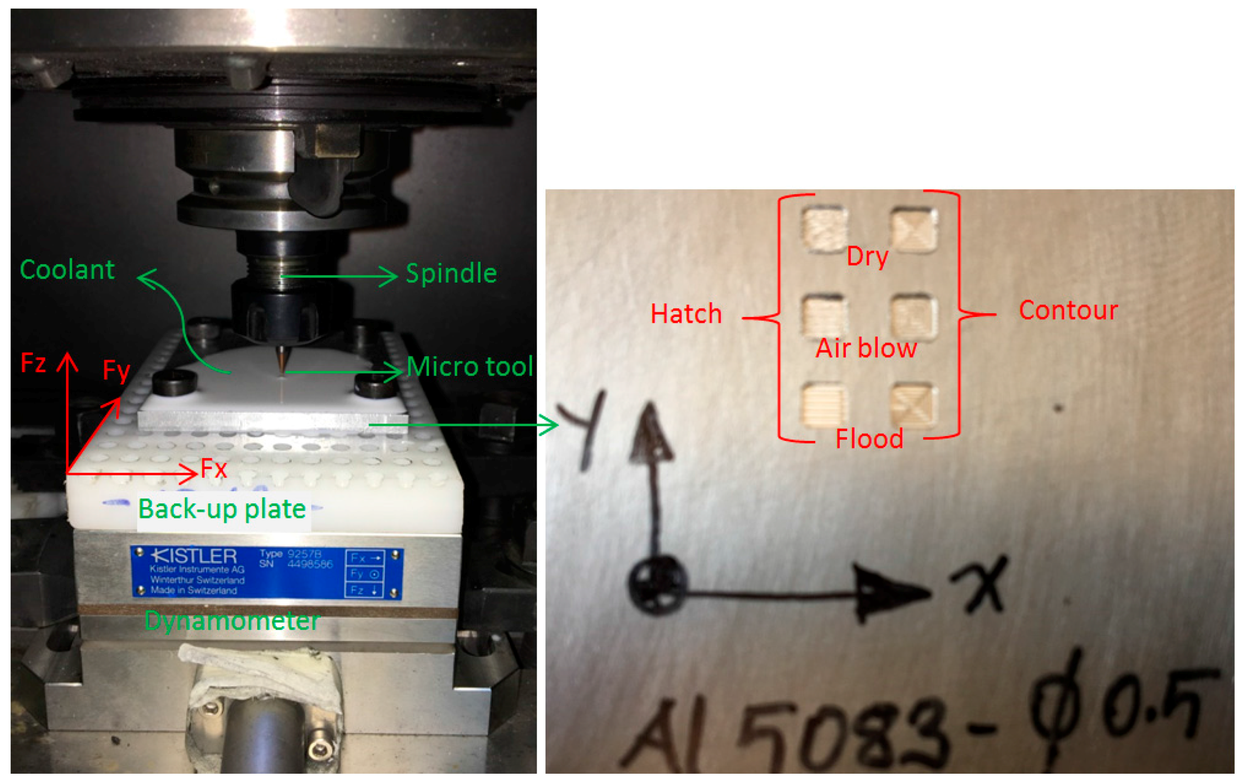
Figure 2.
Geometric characteristics of the micro end mill.

Figure 3.
Cutter path strategies in pocket milling: (a) Hatch zigzag; (b) Contour climb.
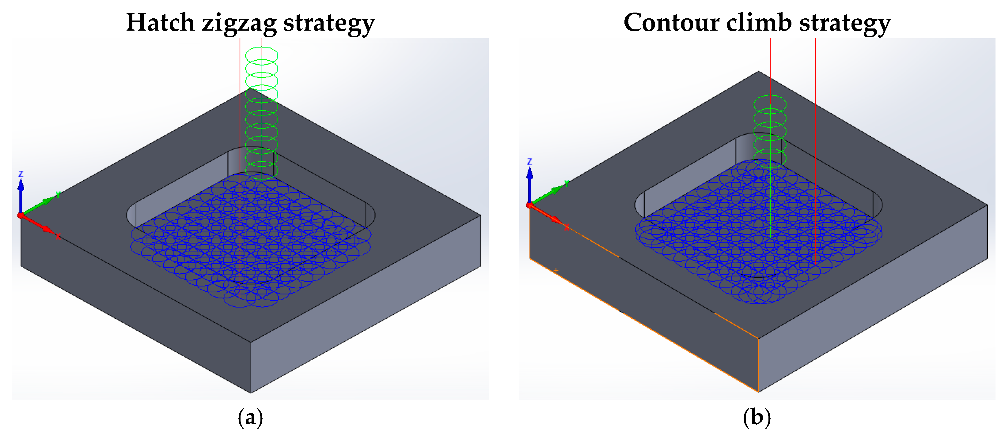
Figure 4.
The effect of cutter path strategies and the coolant factor on cutting force.
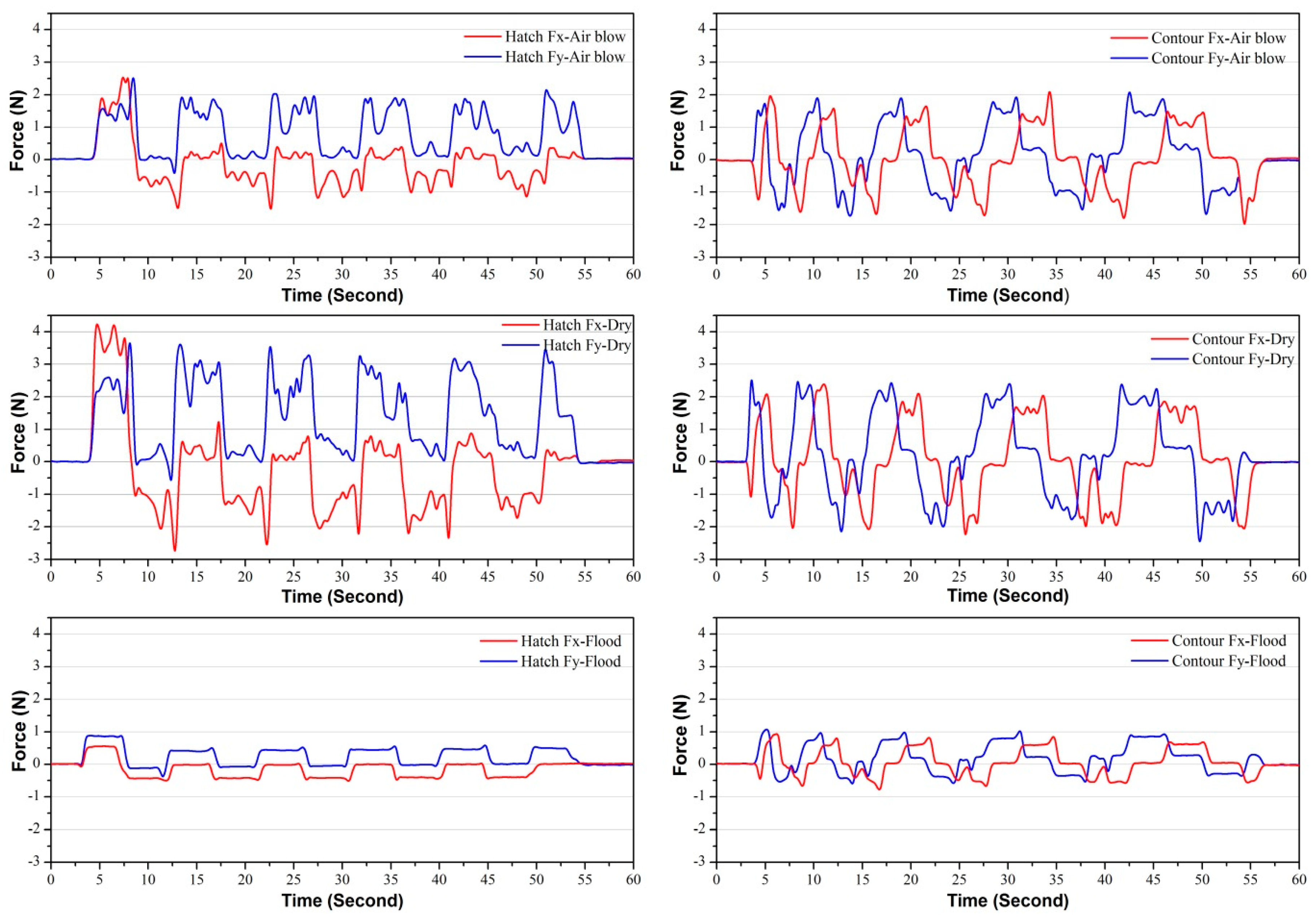
Figure 5.
Surface roughness and 3D surface topography measurements.
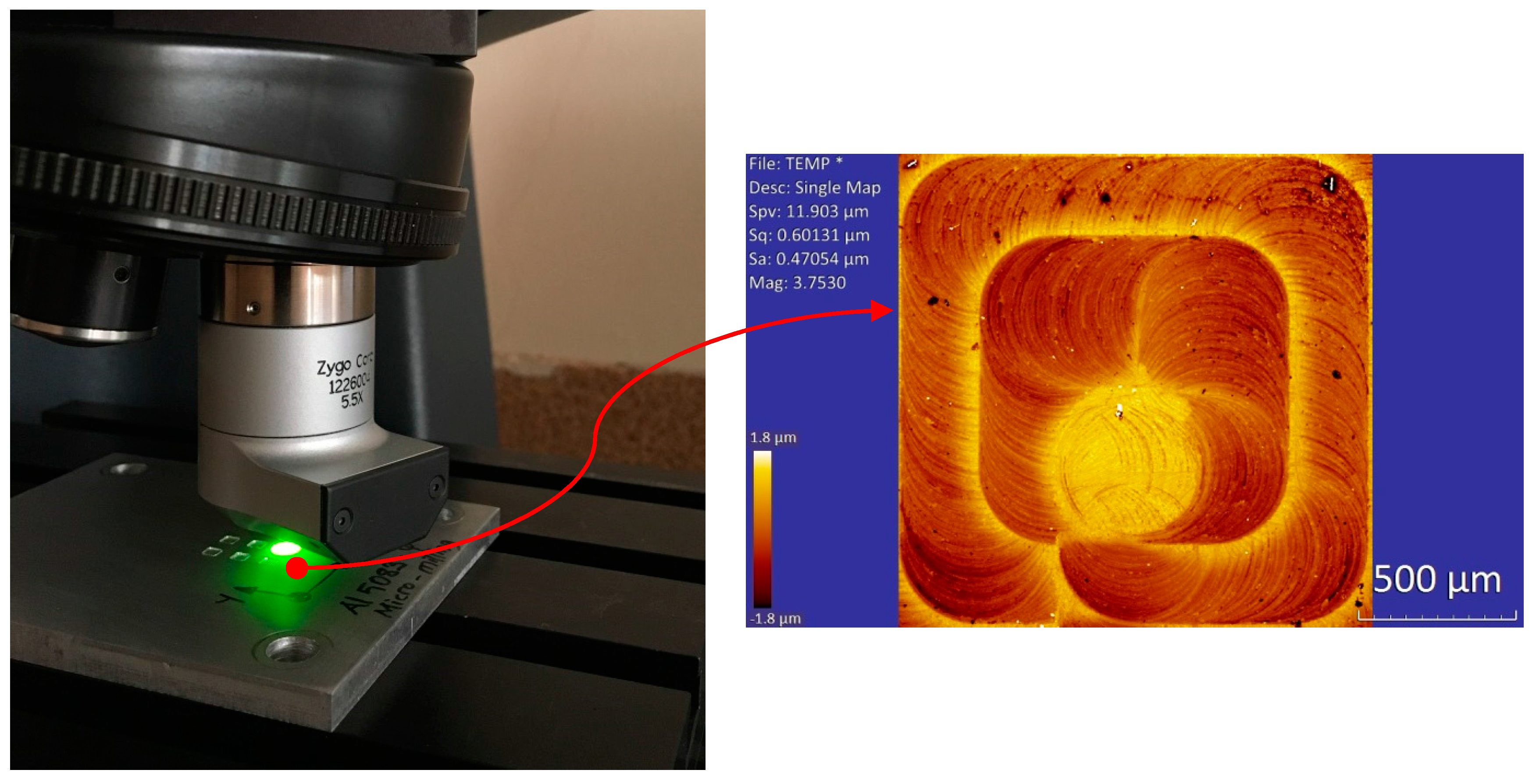
Figure 6.
3D surface topography measurements of the milled pocket.

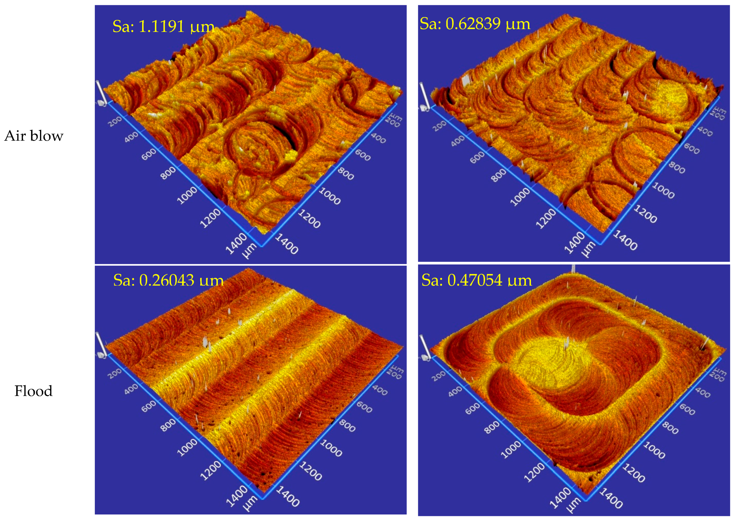
Figure 7.
Comparison of roughness values obtained with different milling strategies.
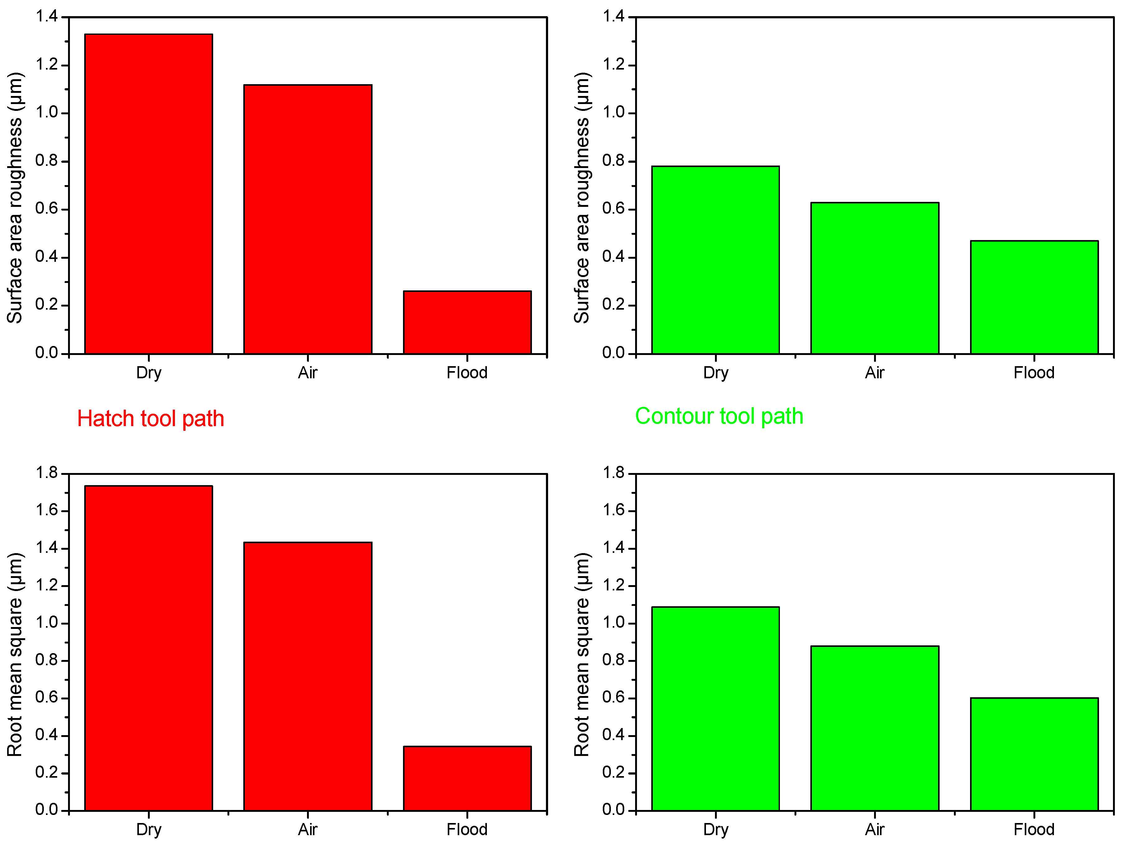
Figure 8.
Comparison of tool wear obtained with different milling strategies.

Table 1.
Chemical compositions and mechanical properties of the AA 5083 H116 aluminum alloy.
| Chemical Composition in Mass % | Mechanical Properties | ||||||||||
|---|---|---|---|---|---|---|---|---|---|---|---|
| Al | Si | Fe | Cu | Mn | Mg | Zn | Cr | Ti | Tensile strength | Yield strength | Elongation |
| 92.4–95.6 | Max. 0.4 | Max. 0.4 | Max. 0.1 | 0.4–1 | 4–4.9 | Max. 0.25 | 0.05–0.25 | Max. 0.15 | 317 MPa | 228 MPa | 16% |
© 2017 by the authors. Licensee MDPI, Basel, Switzerland. This article is an open access article distributed under the terms and conditions of the Creative Commons Attribution (CC BY) license (http://creativecommons.org/licenses/by/4.0/).
Share and Cite
MDPI and ACS Style
Koklu, U.; Basmaci, G. Evaluation of Tool Path Strategy and Cooling Condition Effects on the Cutting Force and Surface Quality in Micromilling Operations. Metals 2017, 7, 426. https://doi.org/10.3390/met7100426
AMA Style
Koklu U, Basmaci G. Evaluation of Tool Path Strategy and Cooling Condition Effects on the Cutting Force and Surface Quality in Micromilling Operations. Metals. 2017; 7(10):426. https://doi.org/10.3390/met7100426
Chicago/Turabian StyleKoklu, Ugur, and Gültekin Basmaci. 2017. "Evaluation of Tool Path Strategy and Cooling Condition Effects on the Cutting Force and Surface Quality in Micromilling Operations" Metals 7, no. 10: 426. https://doi.org/10.3390/met7100426
Note that from the first issue of 2016, this journal uses article numbers instead of page numbers. See further details here.