Experimental Investigation of Forming Forces in Frictional Stir Incremental Forming of Aluminum Alloy AA6061-T6


1
Department of Mechanical & Manufacturing Engineering, Faculty of Engineering, Universiti Putra Malaysia, Serdang 43400, Malaysia
2
Advanced Manufacturing Research Centre, Department of Mechanical & Manufacturing Engineering, Faculty of Engineering, Universiti Putra Malaysia, Serdang 43400, Malaysia
3
Middle Technical University-Institute of Technology, Baghdad 10001, Iraq
4
Department of Aerospace Engineering, Faculty of Engineering, University Putra Malaysia, Serdang 43400, Malaysia
*
Author to whom correspondence should be addressed.
Metals 2017, 7(11), 484; https://doi.org/10.3390/met7110484
Submission received: 4 September 2017
/
Revised: 2 October 2017
/
Accepted: 17 October 2017
/
Published: 7 November 2017
(This article belongs to the Special Issue Metallic Materials and Manufacturing)
Abstract
:The incremental sheet forming (ISF) process is an emerging flexible sheet-forming process, which is adequate for the manufacturing of unique or small-volume batches. Single-point incremental forming (SPIF) is the original technology of incremental sheet-forming processes. In this article, frictional stir-assisted SPIF was used to deform AA6061-T6 aluminum alloy. Experimental tests were conducted to measure the forming forces during this process for the concerned lightweight material. The influence of process parameters was investigated, which included tool rotation speed, feed rate, step size and tool diameter on the produced forming forces. A Taguchi technique for the design of experiment (DOE) and the varying wall angle conical frustum (VWACF) test was employed in this study. The results show that the rotation spindle speed was the most dominant parameter that affects the forming forces, followed by the step size, feed rate and tool diameter. In addition, the interaction between the feed rate and step size has a notable impact on the values of the forming forces.
1. Introduction
Incremental sheet forming (ISF) is described as having an inherent flexibility, high formability, low cost and low-forming forces compared to traditional sheet metal forming processes. Based on the evident advantages of this process, ISF is a promising forming process, as it is highly impressive from both the academic and industrial perspectives [1,2,3]. In the beginning of the last century, high interest focused on improving and employing lightweight materials in various industrial applications, such as aerospace, marine and automobile sectors [4,5]. The present applications of ISF are in the aerospace [5], transportation [6] and medical [7] fields. One of the important applications of the incremental forming is the incremental roller burnishing technique, which is used to finish the coated surface of the forming tools [8] and sheets [9] with very smooth surfaces.
Increasing demands to utilize the lightweight materials in various applications has created a critical challenge in this developed process, which is namely how to deal with low formability materials at room temperature [4,5]. Consequently, heat-assisted ISF processes have been suggested to improve the formability at warm or hot conditions. These methods include electric-assisted ISF, laser-assisted ISF and frictional stir-assisted ISF [5,10,11,12].
In sheet metal forming processes, an adequate level of load is necessary to overcome the yield stress of the sheet metal material to produce the required permanent deformation. Generally, the forming forces that accompany ISF are small compared to those required for traditional forming processes, such as deep drawing and stamping. Known as the single-point incremental forming (SPIF), only the value of the load at the forming tool-sheet metal interface affects the degree of the localized plastic deformation. Thus, an excessive applied load affects the workpiece at the local forming area, which lies under the forming tool [13,14]. Figure 1 explains the basic elements of SPIF. In this figure, a–c are the tool positions during the forming process while ti and tf are the initial and final thickness of the sheet (dimensions in mm) and (Φ) is the wall angle of the formed part which measured in degrees.
The deforming forces in SPIF cannot be initially selected by the designers, which usually occurs in conventional forming processes. There are several factors, which largely help determine these forming loads, such as the application of the forming strategy, tool-sheet interaction and the kinematics of the process [15,16]. The perfect forecasting of forming forces is a crucial task in the process optimization for selecting parameters and the choice of the proper forming equipment to perform the experiments. Therefore, when forming forces exceed the allowable levels, they will affect the tooling stiffness, product quality, jig and fixtures as well as the machines used.
The forming forces in SPIF are characterized by highly intensive and localized deformation that leads to high frictional forces at the tool-sheet contact interface. The prevailing force component is the axial component in the direction of the forming tool [17,18]. Thus, estimation of the maximum forces is an important issue, not for design requirements, but for other significant reasons. These reasons include preserving the tooling machine, guaranteeing the safe usage of hardware, ensuring the quality of the produced parts [13], determining the stress levels and therefore, plastic strains controlling the structure of the component.
Many studies carried out aimed to explain the effect of different parameters on the process forces [13,19,20,21,22,23,24,25]. These studies demonstrated that SPIF forces have proportional relationships with the tool size, step size, sheet thickness, and forming wall angle [26].
Moreover, adjusting the rotational speed [17,27,28,29,30] and applying lubricants [31,32] can effectively reduce these concentrated forces. A few studies have examined the effect of the tool rotation speed on the forming forces in SPIF. Durante et al. [17], during their investigation of the formability of AA7075-T0 with tool speeds ranging from 0–800 rpm, found that the friction decreased and therefore, the forming forces decreased as the tool speed increased. Bagudanch et al. [24] studied the effect of tool diameter, step size and tool rotational speed on the SPIF of AISI-304 stainless steel material. Their experimental results proved that the forming forces are proportional to the tool diameter and step size, while forces decrease with high rotational speeds. Xu et al. [26] conducted an experimental study on AA5052-H32 aluminum alloy with 1.27 mm thickness to analyze the effect of tool rotation in a range of 0–7000 rpm on forming forces, generated temperature and formability. It was demonstrated that in a range of 0–1000 rpm, the friction is the main factor. However, in a range of 2000–7000 rpm, the thermal and dynamic recrystallization effects were the dominant factors. It proved that increasing the rotation speed helped in enhancing the formability, reducing the forming forces and raising the temperature during the process. Moreover, a tool with a laser surface texture (LST) was utilized during the forming process and this study proved that this designed tool played a crucial role in the reduction of friction due to micro channels and the generated hydrodynamic pressure by this texture.
Duflou et al. [13] carried out an experimental investigation to determine the effect of some parameters, such as tool size, wall angle, step size and sheet thickness, on SPIF forces. It was found that increasing the values of these parameters led to increasing forming forces. The effect of the same process parameters was studied by Bahloul et al. [33] to evaluate their outcomes on two important responses: sheet-thinning rates and maximum process forces. Based on the obtained results, the sheet thickness and the wall angle have the most significant effect on the two afore-mentioned responses. In addition, a genetic algorithm was applied to optimize these responses.
In this study, among heat-assisted incremental forming techniques, frictional stir-assisted SPIF has been applied to deform AA6061-T6 aluminum alloy, which has been employed in a wide range of applications in different industrial sectors. In addition to the advantages of heat-assisted ISF, frictional stir-assisted SPIF displays superior benefits, as it does not require an external heating source and has a better final surface finish.
2. Materials and Methods
2.1. Material Characterization
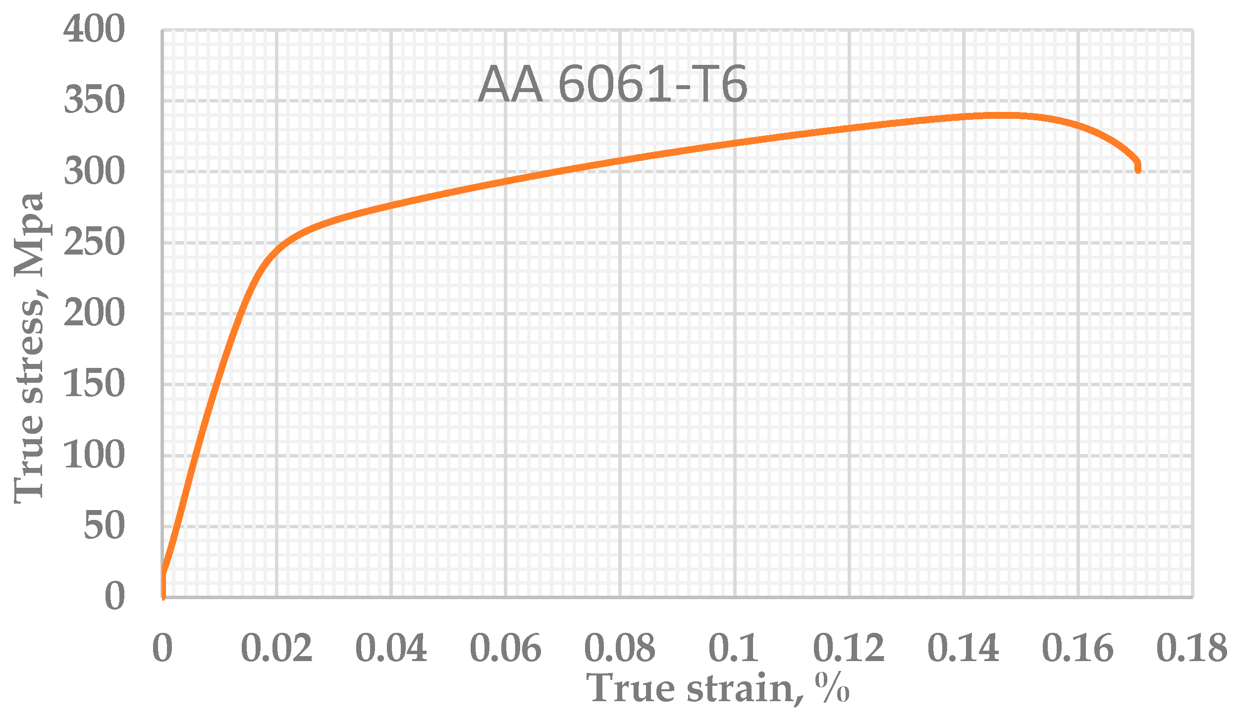
In this section, the uniaxial tensile test was used to obtain the true stress-strain curve and subsequently, the mechanical properties of AA 6060-T6 with a nominal sheet thickness of 2 mm. The dimensions of the specimen are obtained according to ASTM E8M standard. Figure 2 presents the sub-size tensile test specimen.
2.2. Experimental Setup
The essential task of the forming jig is to tightly hold the sheet metal specimen for the forming process. The forming jig used in this work was made from mild steel and comprised of a clamping plate, backing plate, four columns and a lower or base plate. The sheet metal with dimensions of 150 mm × 150 mm × 2 mm was placed between the two clamping and backing plates. The size of the backing plate was 170 mm × 170 mm × 20 mm with a central diameter of 70 mm and rounded by a fillet of 60 mm, which helped to allow the smooth manufacturing of the final part. Moreover, the lower plate is mounted well to the Kistler-type dynamometer (9129AA, Kistler Group, Winterthur, Switzerland), which was used to measure the forming forces. The complete design of the forming jig developed in the current study was attached to the dynamometer and mounted to the CNC (OKUMA MX-45VA) milling machine bed, as depicted in Figure 4.
The forming tools with two diameters, 10 mm and 15 mm, and with a total length of 110 mm, were designed with a hemispherical end to use in the SPIF experiments. These tools are made from high speed steel (HSS), before being hardened and tempered with 60 HRC. The tools tips were polished to reduce the friction action at the tool–sheet contact area, thereby increasing the tool life and decreasing the surface roughness of the final parts. Figure 5 shows the forming tools.
2.3. Experiments
Studying the forming forces in SPIF is the crucial objective when preparing for this new technology as the obtained plastic deformation is mainly related to the magnitudes of these forces. Moreover, selecting the appropriate forming machine, designing the forming tools, determining the excessive sheet thinning, investigating the forming mechanisms and understanding the failure conditions of the sheet metal are critical when determining the values and directions of these forces. Some methods were utilized to measure the forming forces, such as the cantilever sensor employed by Jeswiet [16]; the dynamometer applied by several researchers, such as Duflou et al. [13,27,28,34,35,36]; and the Wheatstone bridge designed in a previous study [37].
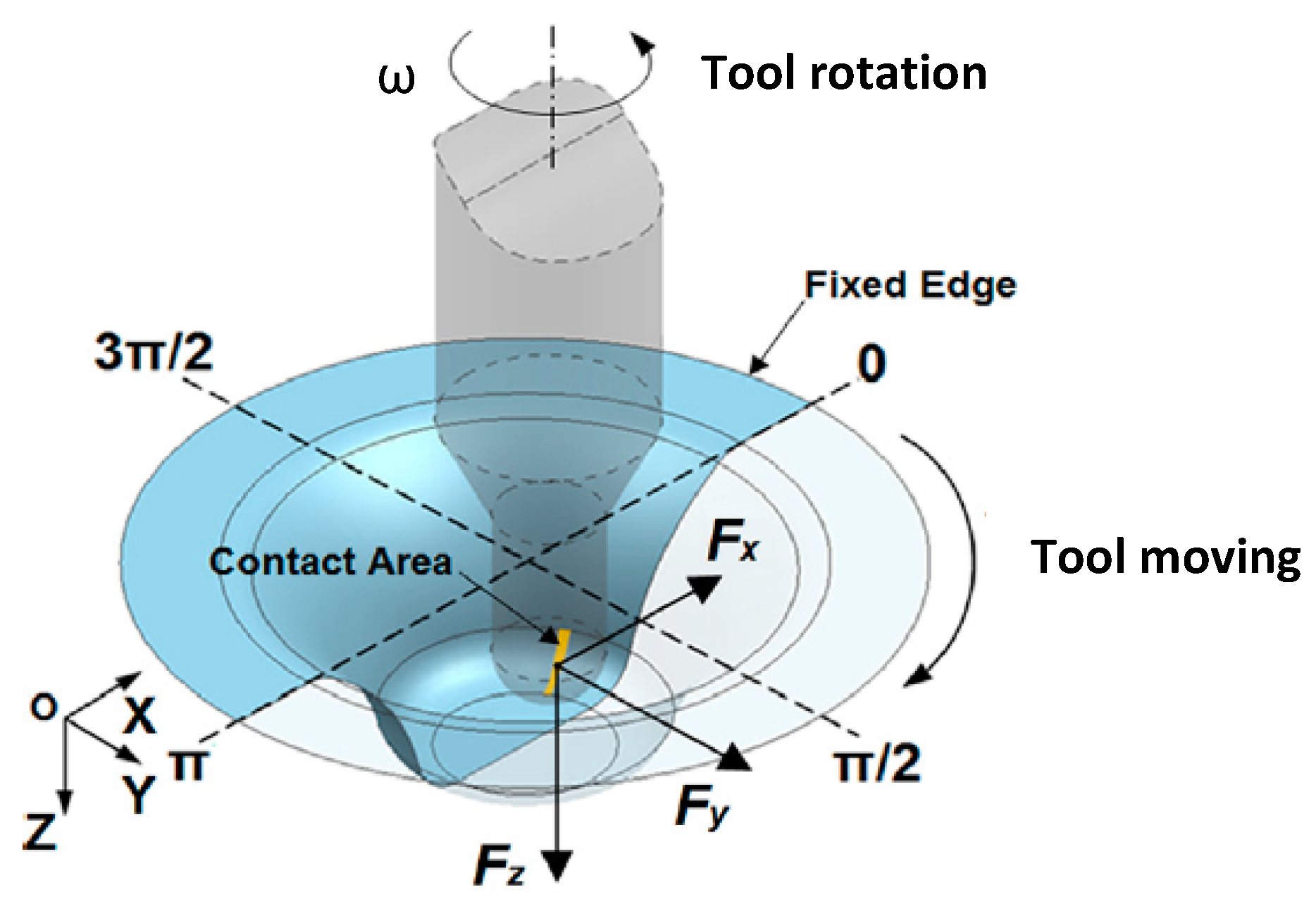
Usually, the forming forces in SPIF can be represented with the three orthogonal Cartesian coordinates system: x, y and z (Figure 6). Fx and Fy are the forming force components that act in the workpiece plane. Fz is the force that is applied along the forming tool axis and is normal to the workpiece plane, while Fx-p is the value of Fz at the peak point. Fxy is the resultant force that acts in the xy plane. Therefore, the Fxy and the resultant force (FR) in SPIF can be estimated by the two equations below [29]:
In this work, a force measuring system was used to measure the forming forces in three directions. This system is consisted of a Kistler 9129AA type dynamometer, a 5070A signal amplifier (PRIAMUS SYSTEM TECHNOLOGIES AG, Schaffhausen, Switzerland), a type 5697A DAQ data card and Dyno Ware (Version 2.6.5.16, Kistler Group, Winterthur, Switzerland, 2010), which were used to record the force values.
A varying wall angle conical frustum test (VWACF) was employed to conduct the experiments due to its homogeneous geometry with a symmetrical section [38]. Figure 7 shows the designed dimensions of the required conical frustum.
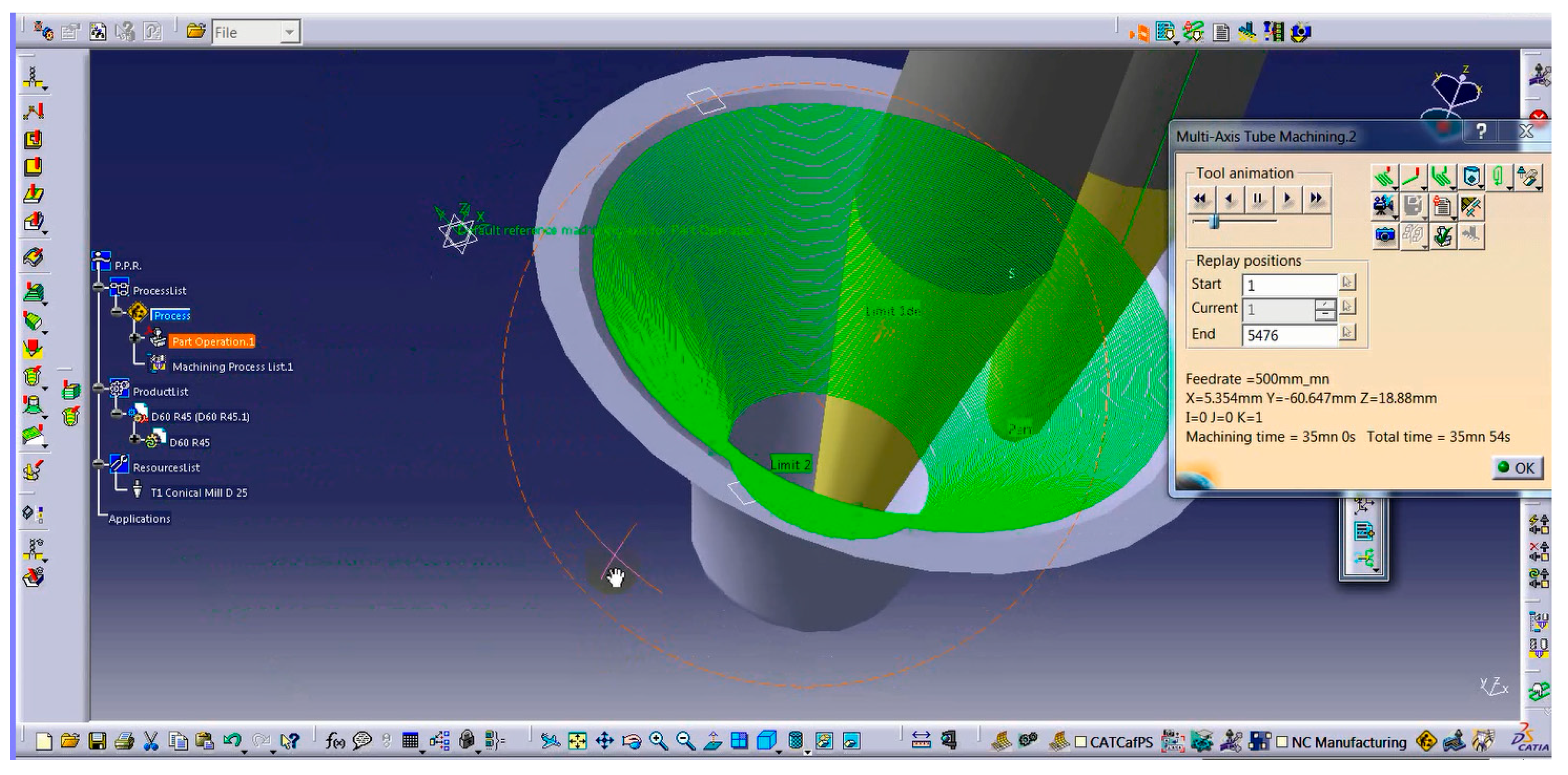
In this study, the spiral tool path with a constant step size was chosen to create the tool trajectory because it almost creates a pure stretch deformation and therefore, generates a uniform sheet thickness [39]. In addition, it helps to eliminate the force peaks and simultaneously does not leave stretch marks on the sheet surface. In contrast, these cons usually take place with the counter tool path. The CAD/CAM software CATIA (V5.19, Dassault systems, 2010) was employed to model the required profile and create the spiral tool path using NC (numerical control) codes, as shown in Figure 8. The part model of the VWACF was designed to have a maximum diameter of 70 mm, a depth of 42.102 mm and the radius of varying slopes of the modeled part of 60 mm, as shown in Figure 7.
During the process, the continuous movement of the tool generates a local heating process and increases the rates of tool wear due to the friction at the tool-sheet contact zone. These two aspects affect both the geometric accuracy and surface finish, which simultaneously leads to an increase in forming forces. Different types of lubricants have been used for SPIF methods to minimize these harmful effects. In the current study, the lubricant SAE (BLAZE RACING SYNTHETIC BLEND 10W-40) was applied to reduce the effects of the friction. The Taguchi method was used to design the experiments with a minimum number to save costs and time consumption during the experiments [40,41]. The design of experiment, which includes selecting the main process parameters and their levels, was in accordance with previous literature. From this literature, it was found that these parameters and their levels depend highly on the material properties. Additionally, the primary tests were conducted to ensure the correct choosing of these parameters and their levels to get satisfactory results. The main process parameters and their selected levels are presented in Table 2, while Table 3 summarized the orthogonal array (L8).
3. Results and Discussion
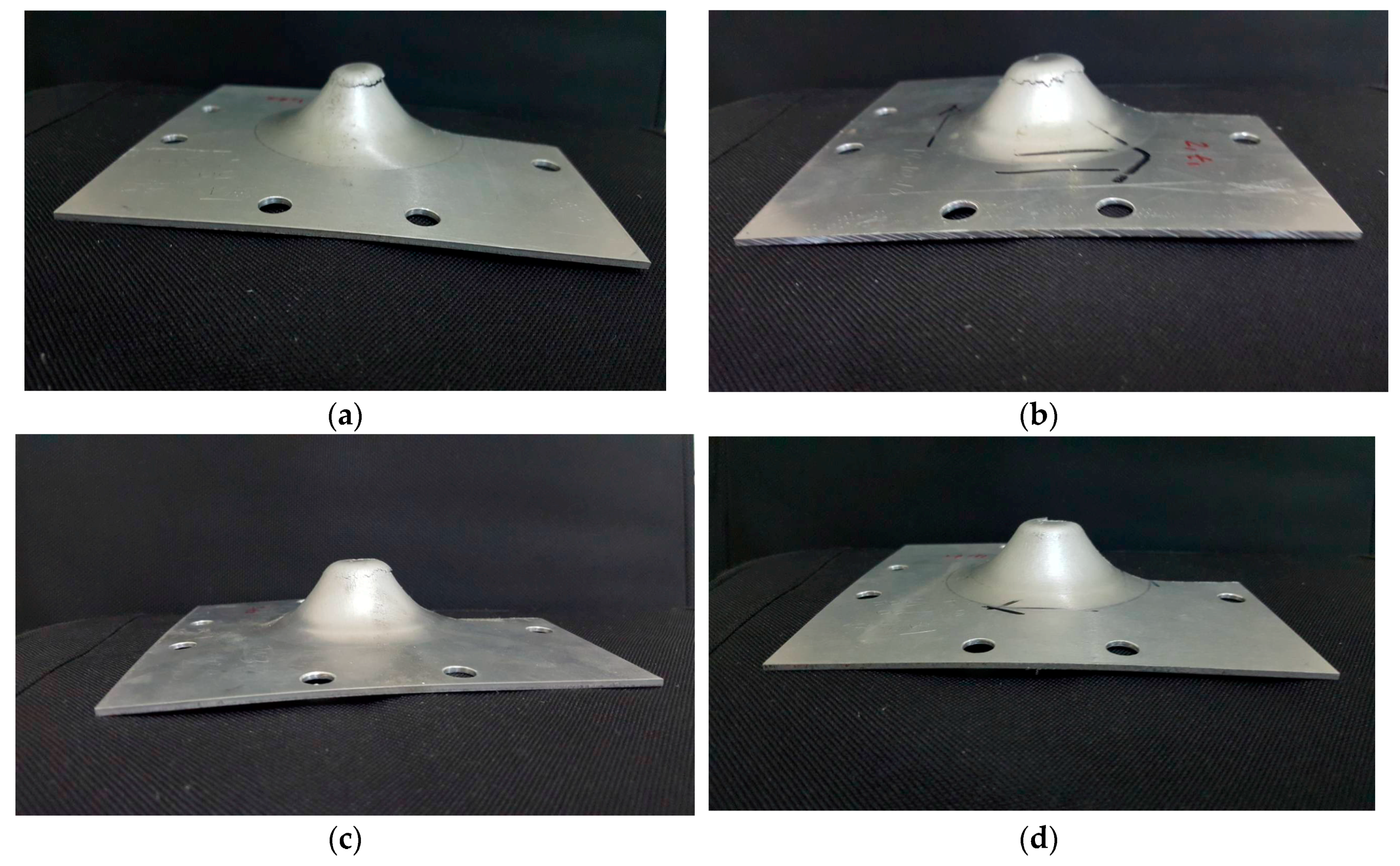
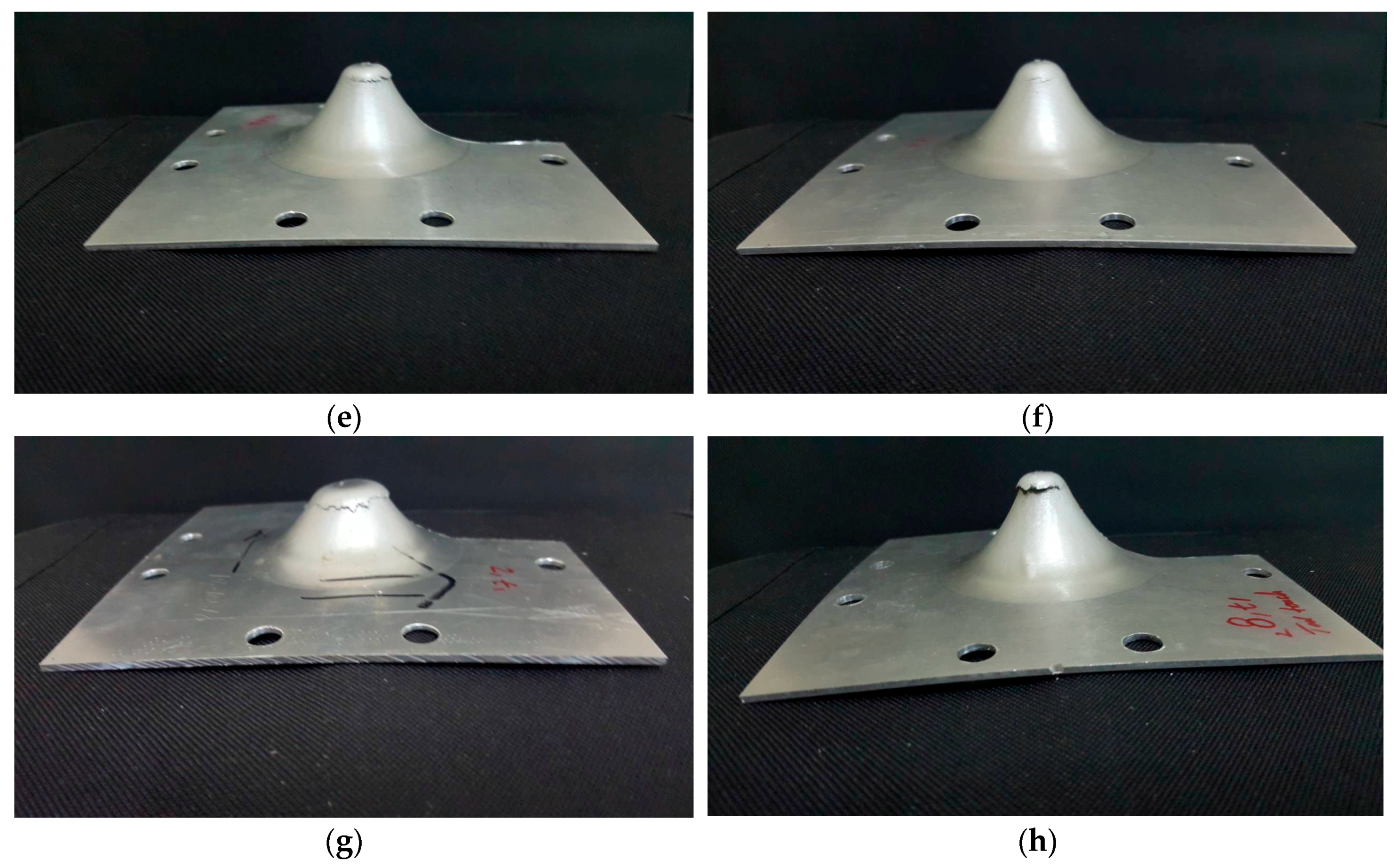
A series of experiments was conducted to evaluate the impact of rotation speed, feed rate, step size and tool diameter on the forming forces during the frictional stir-assisted SPIF. The experiments stopped after the part fractured (Figure 9).
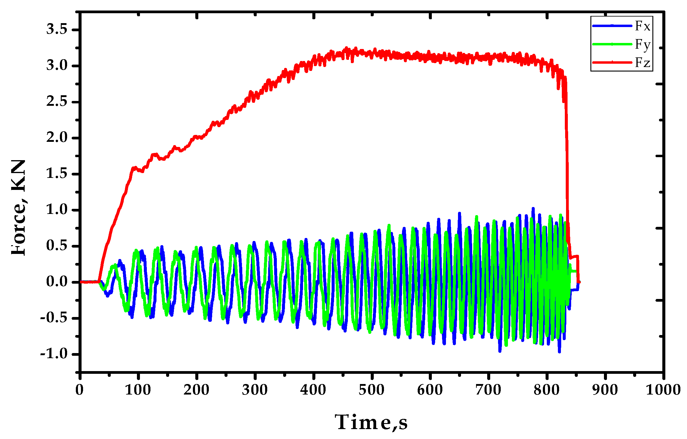
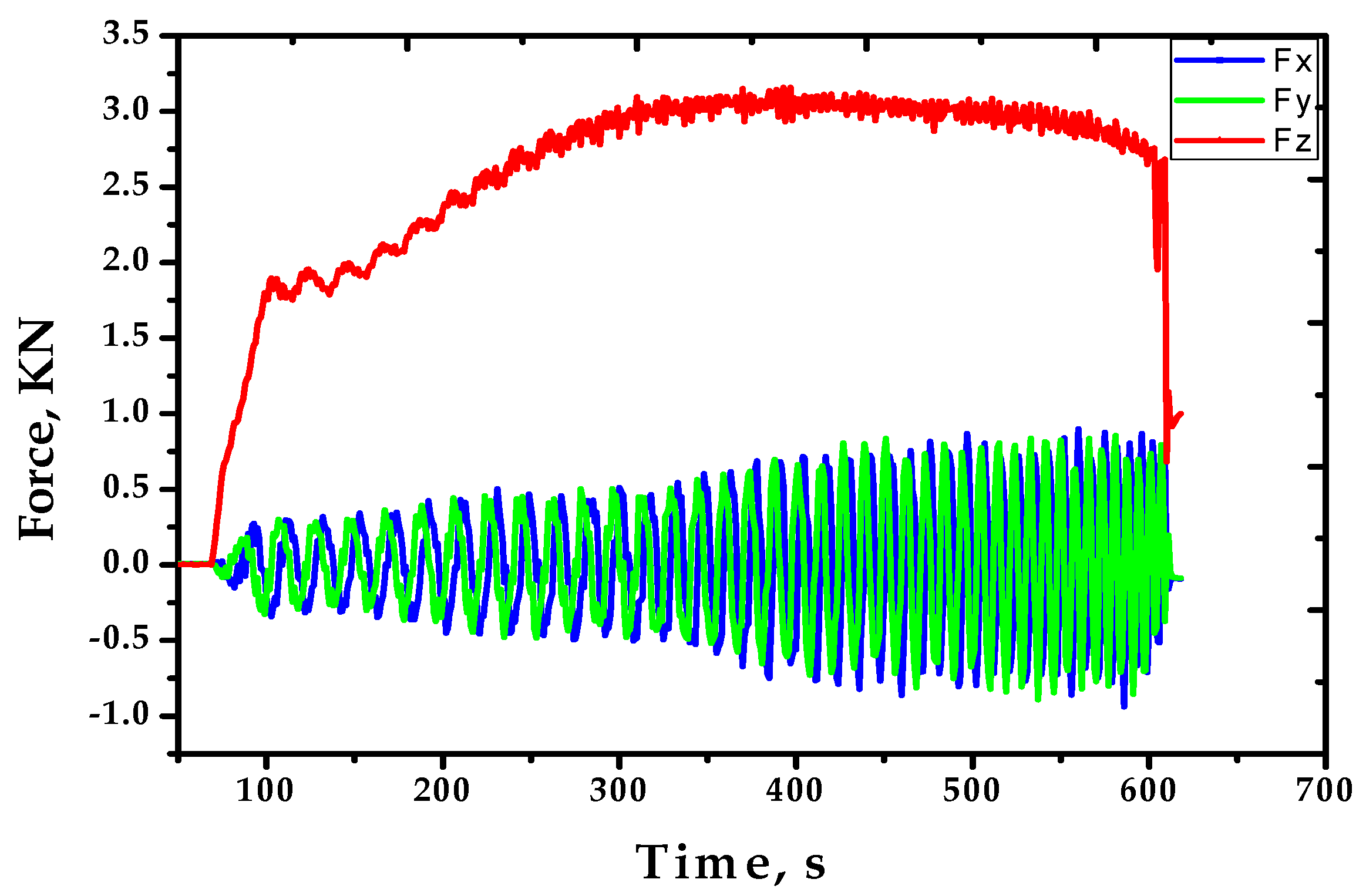
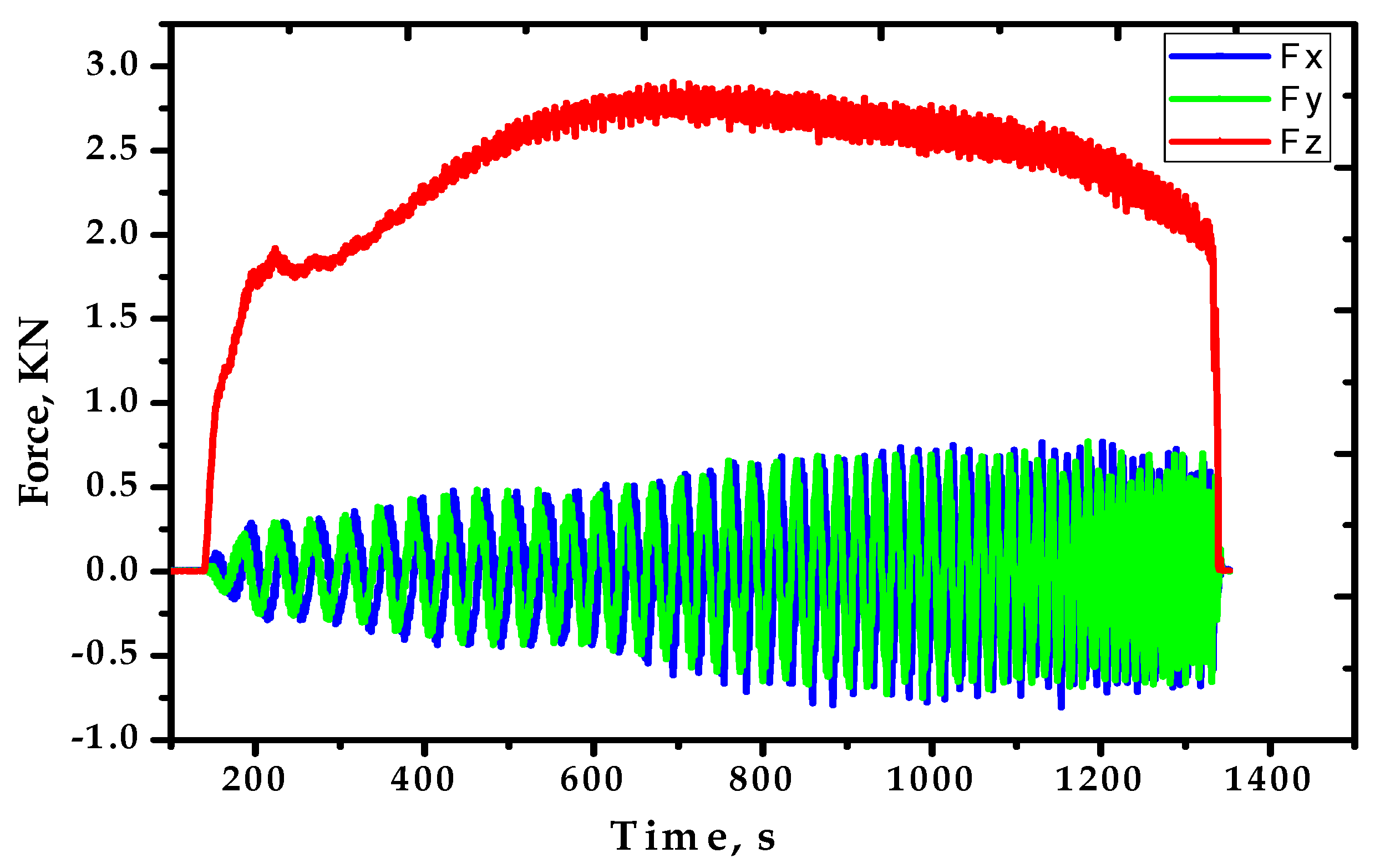
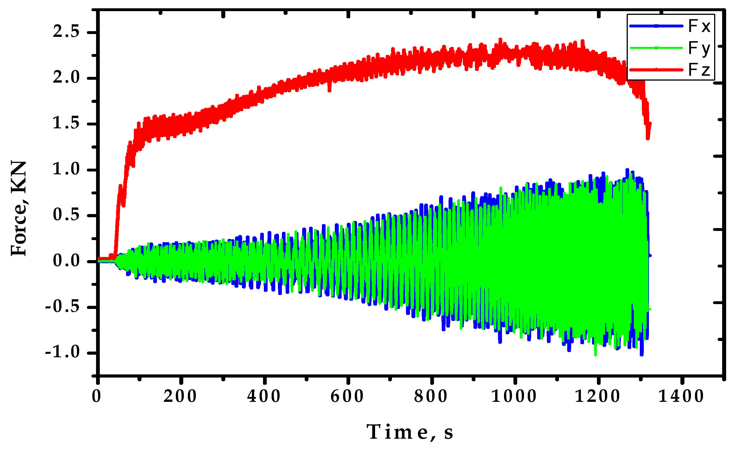
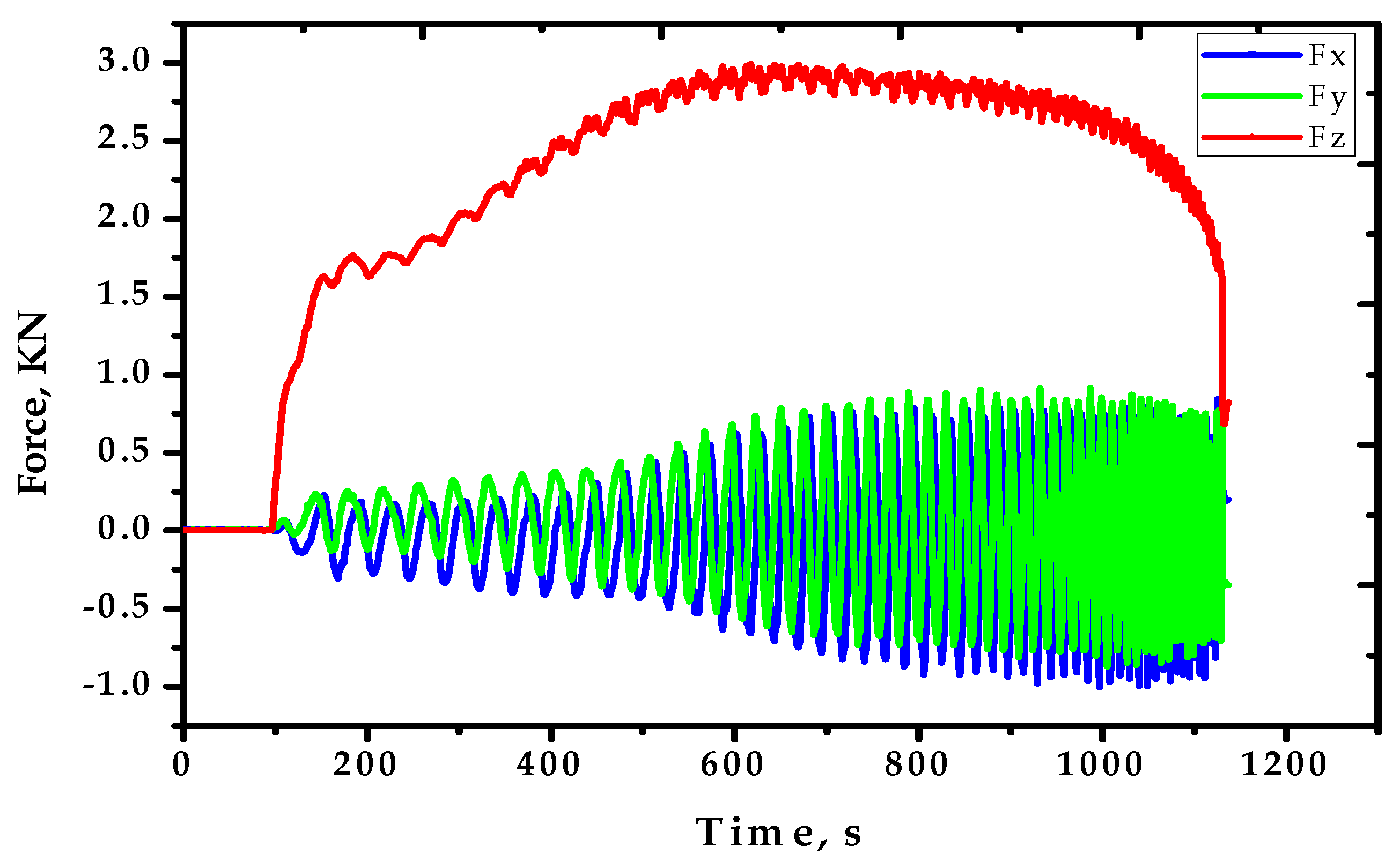
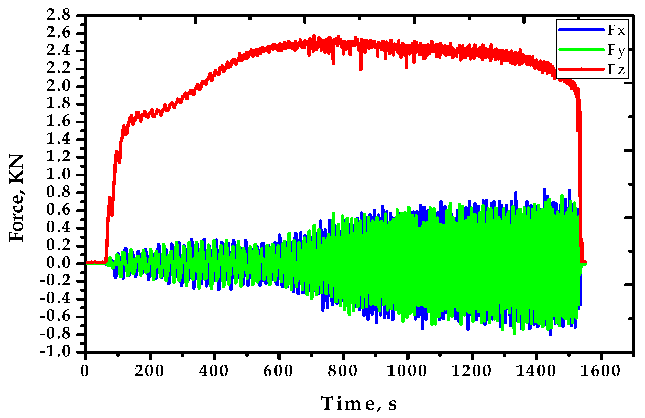
Figure 10, Figure 11, Figure 12, Figure 13, Figure 14, Figure 15, Figure 16 and Figure 17 show the results of the forming forces in three directions (Fz, Fy and Fx) measured by the dynamometer.
Table 4 shows the forming forces in the three directions of x, y and z at peak point and the resultant forces at this point, which is calculated according to Equations (1) and (2).
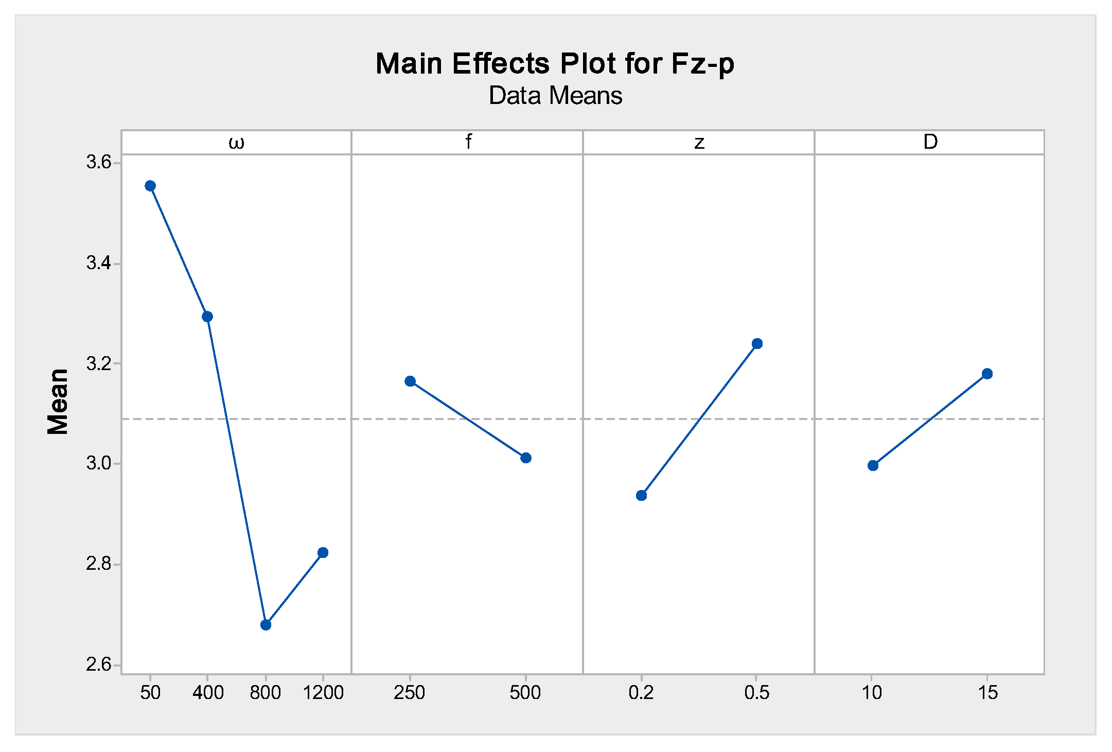
From Table 4, it can be noted that the Fz-p has a greater magnitude than the Fx and Fy forces so it can be considered as a more significant force because it has a direct effect on the magnitude of the resultant forces at the peak point. To evaluate the impact of the various parameters on trends of these forces, analysis of variance (ANOVA) was utilized to obtain the main effects of these parameters on Fz-p (Figure 18). From this figure, it can be demonstrated that the rotation speed has the greater effect on the produced Fz-p, followed by the step size, feed rate and tool diameter, which was shown as a previous study [27]. The dotted line in this figure refers to the mean value of the Fz-p. Using a high rotation speed leads to high friction at the tool-sheet zone and generates a highly localized heat, which helps to reduce the forming forces [17,29]. Moreover, the increase in the values of the step size and tool diameter causes an increase in the forming forces. To complete the part, the tool needs to travel continuously inside the profile and this required more pushing of the material during forming. The reaction of the material will be greater with high step size values, finally increasing the forces. In addition, when using a large diameter, the contact area is greater than that of a small diameter, so the forming forces increase as the tool diameter increases [27].
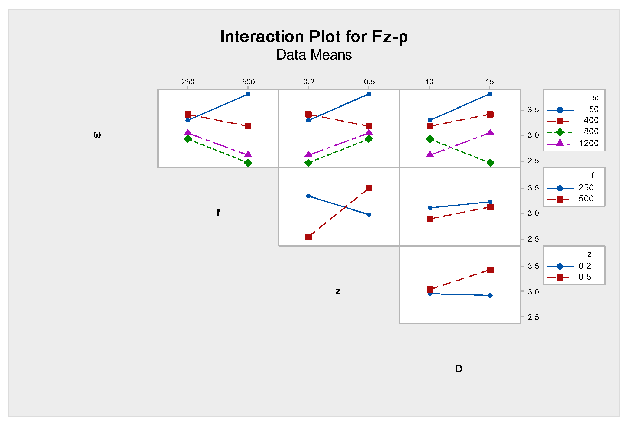
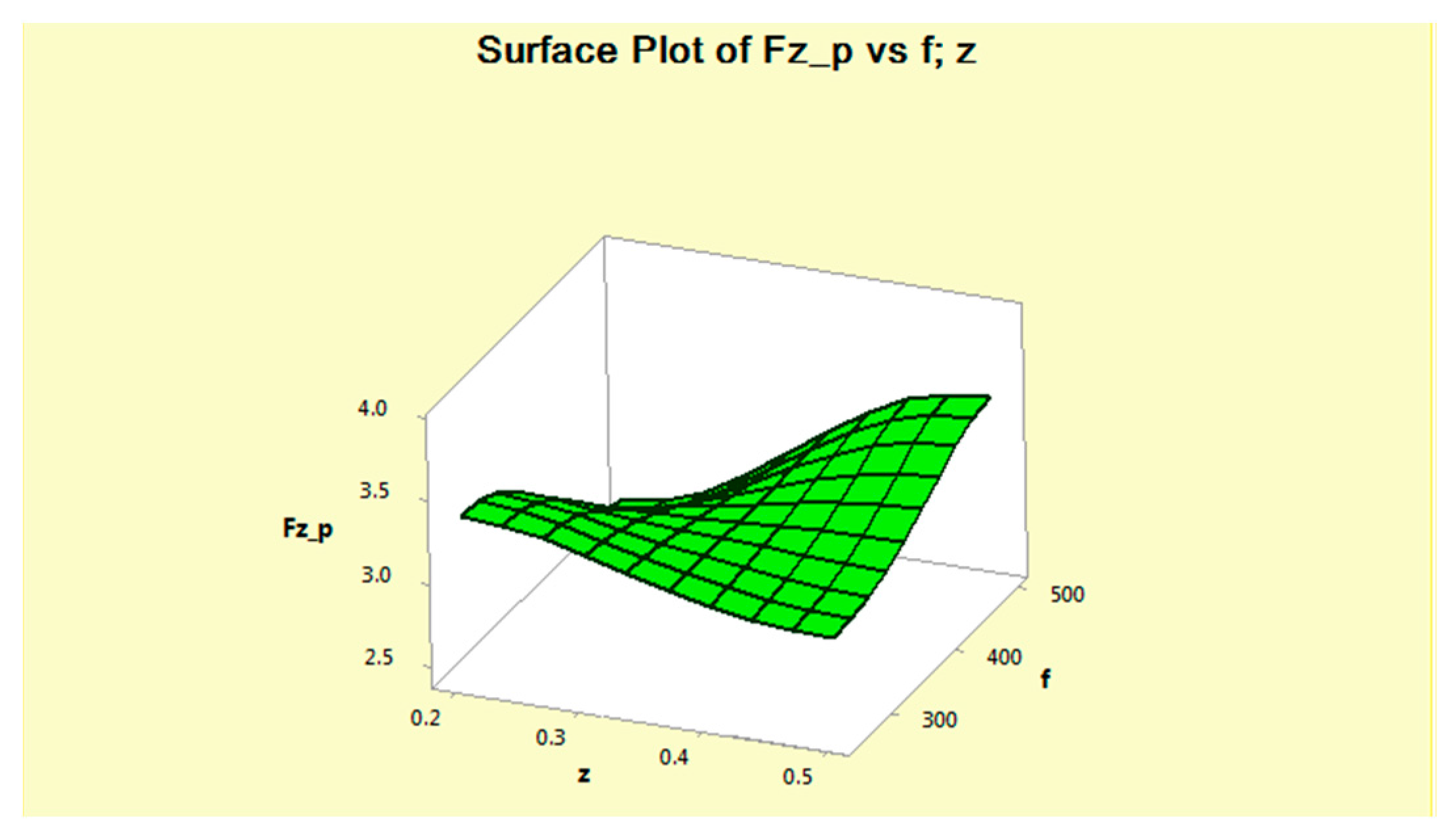
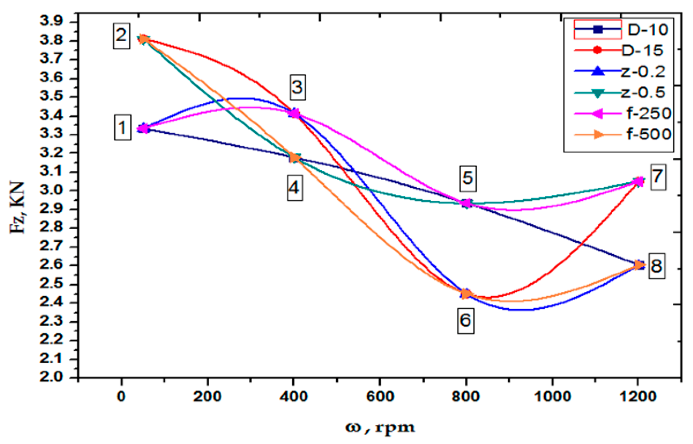
The decrease in Fz-p is not always proportional to an increase in the rotation speed where after ω = 800 rpm, this force returned to have an increasing trend with an increase in the rotation speed. This is due to the interaction effects between the different studied parameters as they appear in Figure 19, Figure 20 and Figure 21. It can be noted from Figure 19 that the main interaction was between the feed rate and step size on the maximum value of the axial force, while Figure 20 shows this interaction in the surface plot. Figure 21 shows that the minimum axial forming force Fz-p happened at ω = 800 rpm, f = 500 mm/min, z = 0.2 mm and D = 15 mm (run 6).
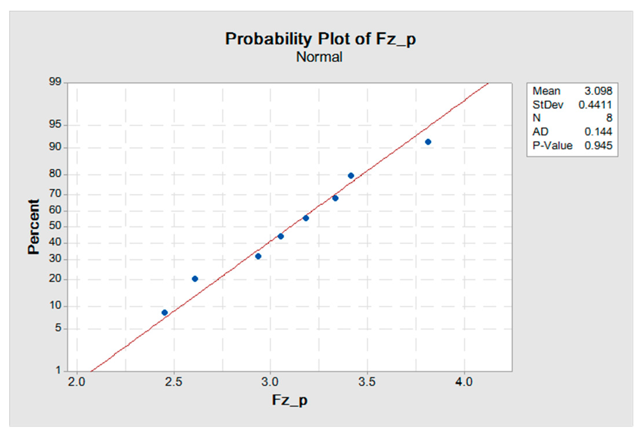
The normal distributions of the values of the Fz-p are explained in Figure 22. The values of this force follow the normal distribution.
4. Conclusions
In the current study, frictional stir-assisted SPIF was applied for deformation of the AA6061-T6 aluminum alloy. The aim was to investigate the impact of rotational tool speed, feed rate, step size and tool diameter on the values of the forming forces during the forming process. The results showed the following interesting points:
- (1)
- Increasing the rotation speed has the main effect of reducing the forming forces.
- (2)
- In addition, the interaction between the different process parameters has a notable influence on these forces, especially the interaction between the feed rate and step size as discussed above.
- (3)
- The other parameter had a smaller effect compared with the rotation speed. Thus, controlling the tool rotation speed is an important issue in reducing the forming forces in SPIF.
Acknowledgments
The authors would like to thank Iraqi Government for the PhD scholarship and Research Management Centre, Universiti Putra Malaysia with the research grant (GP-IPS/2016/9479500), which enable the research to be carried out successfully.
Author Contributions
B.T.H.T Baharudin and Q. M. Azpen conceived and designed the experiments; Q. M. Azpen performed the experiments; B.T.H.T. Baharudin and Shamsuddin Sulaima analyzed the data; F. Mustapha acquired the data on the force sensors; Q. M. Azpen wrote the paper.
Conflicts of Interest
The authors declare no conflict of interest with any other research work.
References
- Cao, T.; Lu, B.; Xu, D.; Zhang, H.; Chen, J.; Long, H.; Cao, J. An efficient method for thickness prediction in multi-pass incremental sheet forming. Int. J. Adv. Manuf. Technol. 2015, 77, 469–483. [Google Scholar] [CrossRef]
- Ingarao, G.; Di Lorenzo, R.; Micari, F. Sustainability issues in sheet metal forming processes: An overview. J. Clean. Prod. 2011, 19, 337–347. [Google Scholar] [CrossRef]
- Zhang, Q.; Xiao, F.; Guo, H.; Li, C.; Gao, L.; Guo, X.; Han, W.; Bondarev, A. Warm negative incremental forming of magnesium alloy AZ31 Sheet: New lubricating method. J. Mater. Process. Technol. 2010, 210, 323–329. [Google Scholar] [CrossRef]
- Ambrogio, G.; Filice, L.; Gagliardi, F. Formability of lightweight alloys by hot incremental sheet forming. Mater. Des. 2012, 34, 501–508. [Google Scholar] [CrossRef]
- Bao, W.; Chu, X.; Lin, S.; Gao, J. Experimental investigation on formability and microstructure of AZ31B alloy in electropulse-assisted incremental forming. Mater. Des. 2015, 87, 632–639. [Google Scholar] [CrossRef]
- Jeswiet, J.; Micari, F.; Hirt, G.; Bramley, A.; Duflou, J.; Allwood, J. Asymmetric single point incremental forming of sheet metal. CIRP Ann. Manuf. Technol. 2005, 54, 88–114. [Google Scholar] [CrossRef]
- Ambrogio, G.; De Napoli, L.; Filice, L.; Gagliardi, F.; Muzzupappa, M. Application of incremental forming process for high customised medical product manufacturing. J. Mater. Process. Technol. 2005, 162, 156–162. [Google Scholar] [CrossRef]
- Franzen, V.; Witulski, J.; Brosius, A.; Trompeter, M.; Tekkaya, A. Thermally sprayed coatings as effective tool surfaces in sheet metal forming applications. J. Therm. Spray Technol. 2011, 20, 939–947. [Google Scholar] [CrossRef]
- Astarita, A.; Carrino, L.; Durante, M.; Formisano, A.; Langella, A.; Minutolo, F.; Paradiso, V.; Squillace, A. Experimental study on the incremental forming of coated aluminum alloy sheets. Key Eng. Mater. 2014, 622–623, 398–405. [Google Scholar] [CrossRef]
- Xu, D.; Lu, B.; Cao, T.; Chen, J.; Long, H.; Cao, J. A comparative study on process potentials for frictional stir-and electric hot-assisted incremental sheet forming. Procedia Eng. 2014, 81, 2324–2329. [Google Scholar] [CrossRef]
- Li, C.; Jiang, S.; Zhang, K. Pulse current-assisted hot-forming of light metal alloy. Int. J. Adv. Manuf. Technol. 2012, 63, 931–938. [Google Scholar] [CrossRef]
- Asghar, J.; Reddy, N. Importance of tool configuration in incremental sheet metal forming of difficult to form materials using electro-plasticity. Lect. Notes Eng. Comput. Sci. 2013, 2206, 1734–1738. [Google Scholar]
- Duflou, J.; Tunckol, Y.; Szekeres, A.; Vanherck, P. Experimental study on force measurements for single point incremental forming. J. Mater. Process. Technol. 2007, 189, 65–72. [Google Scholar] [CrossRef]
- Ren, H.; Moser, N.; Zhang, Z.; Ndip-Agbor, E.; Smith, J.; Ehmann, K.F.; Cao, J. Effects of tool positions in accumulated double-sided incremental forming on part geometry. J. Manuf. Sci. Eng. 2015, 137. [Google Scholar] [CrossRef]
- Li, Y.; Liu, Z.; Lu, H.; Daniel, W.B.; Liu, S.; Meehan, P.A. Efficient force prediction for incremental sheet forming and experimental validation. Int. J. Adv. Manuf. Technol. 2014, 73, 571–587. [Google Scholar] [CrossRef]
- Ambrogio, G.; Filice, L.; Micari, F. A force measuring based strategy for failure prevention in incremental forming. J. Mater. Process. Technol. 2006, 177, 413–416. [Google Scholar] [CrossRef]
- Durante, M.; Formisano, A.; Langella, A.; Minutolo, F.M.C. The influence of tool rotation on an incremental forming process. J. Mater. Process. Technol. 2009, 209, 4621–4626. [Google Scholar] [CrossRef]
- Al-Ghamdi, K.A.; Hussain, G. Forming forces in incremental forming of a geometry with corner feature: Investigation into the effect of forming parameters using response surface approach. Int. J. Adv. Manuf. Technol. 2015, 76, 2185–2197. [Google Scholar] [CrossRef]
- Jeswiet, J.; Duflou, J.R.; Szekeres, A. Forces in single point and two point incremental forming. Adv. Mater. Res. 2005, 6–8, 449–456. [Google Scholar] [CrossRef]
- Duflou, J.R.; Szekeres, A.; Vanherck, P. Force measurements for single point incremental forming: An experimental study. Adv. Mater. Res. 2005, 6–8, 441–448. [Google Scholar] [CrossRef]
- Duflou, J.; Callebaut, B.; Verbert, J.; De Baerdemaeker, H. Laser assisted incremental forming: Formability and accuracy improvement. CIRP Ann. Manuf. Technol. 2007, 56, 273–276. [Google Scholar] [CrossRef]
- Duflou, J.; Callebaut, B.; Verbert, J.; De Baerdemaeker, H. Improved SPIF performance through dynamic local heating. Int. J. Mach. Tools Manuf. 2008, 48, 543–549. [Google Scholar] [CrossRef]
- Filice, L.; Ambrogio, G.; Micari, F. On-line control of single point incremental forming operations through punch force monitoring. CIRP Ann. Manuf. Technol. 2006, 55, 245–248. [Google Scholar] [CrossRef]
- Ambrogio, G.; Duflou, J.; Filice, L.; Aerens, R. Some considerations on force trends in Incremental Forming of different materials. AIP Conf. Proc. 2007, 907. [Google Scholar] [CrossRef]
- Aerens, R.; Eyckens, P.; Van Bael, A.; Duflou, J. Force prediction for single point incremental forming deduced from experimental and FEM observations. Int. J. Adv. Manuf. Technol. 2010, 46, 969–982. [Google Scholar] [CrossRef]
- Nee, A.Y. Handbook of Manufacturing Engineering and Technology; Springer: London, UK, 2015. [Google Scholar]
- Bagudanch, I.; Centeno, G.; Vallellano, C.; Garcia-Romeu, M. Forming force in single point incremental forming under different bending conditions. Procedia Eng. 2013, 63, 354–360. [Google Scholar] [CrossRef]
- Centeno, G.; Bagudanch, I.; Martínez-Donaire, A.; Garcia-Romeu, M.L.; Vallellano, C. Critical analysis of necking and fracture limit strains and forming forces in single-point incremental forming. Mater. Des. 2014, 63, 20–29. [Google Scholar] [CrossRef]
- Xu, D.; Wu, W.; Malhotra, R.; Chen, J.; Lu, B.; Cao, J. Mechanism investigation for the influence of tool rotation and laser surface texturing (LST) on formability in single point incremental forming. Int. J. Mach. Tools Manuf. 2013, 73, 37–46. [Google Scholar] [CrossRef]
- Palumbo, G.; Brandizzi, M. Experimental investigations on the single point incremental forming of a titanium alloy component combining static heating with high tool rotation speed. Mater. Des. 2012, 40, 43–51. [Google Scholar] [CrossRef]
- Hussain, G.; Gao, L.; Hayat, N.; Cui, Z.; Pang, Y.; Dar, N. Tool and lubrication for negative incremental forming of a commercially pure titanium sheet. J. Mater. Process. Technol. 2008, 203, 193–201. [Google Scholar] [CrossRef]
- Azevedo, N.G.; Farias, J.S.; Bastos, R.P.; Teixeira, P.; Davim, J.P.; de Sousa, R.J.A. Lubrication aspects during single point incremental forming for steel and aluminum materials. Int. J. Precis. Eng. Manuf. 2015, 16, 589–595. [Google Scholar] [CrossRef]
- Bahloul, R.; Arfa, H.; Salah, H.B. Application of response surface analysis and genetic algorithm for the optimization of single point incremental forming process. Key Eng. Mater. 2013, 554–557, 1265–1272. [Google Scholar] [CrossRef]
- Henrard, C.; Bouffioux, C.; Eyckens, P.; Sol, H.; Duflou, J.; Van Houtte, P.; Van Bael, A.; Duchene, L.; Habraken, A. Forming forces in single point incremental forming: Prediction by finite element simulations, validation and sensitivity. Comput. Mech. 2011, 47, 573–590. [Google Scholar] [CrossRef]
- Ziran, X.; Gao, L.; Hussain, G.; Cui, Z. The performance of flat end and hemispherical end tools in single-point incremental forming. Int. J. Adv. Manuf. Technol. 2010, 46, 1113–1118. [Google Scholar] [CrossRef]
- Martínez-Romero, O.; García-Romeu, M.L.; Olvera-Trejo, D.; Bagudanch, I.; Elías-Zúñiga, A. Tool dynamics during single point incremental forming process. Procedia Eng. 2014, 81, 2286–2291. [Google Scholar] [CrossRef]
- Li, Y.L.; Liu, Z.B.; Lu, H.B.; Daniel, W.; Meehan, P.A. Experimental study and efficient prediction on forming forces in incremental sheet forming. Adv. Mater. Res. 2014, 939, 313–321. [Google Scholar] [CrossRef]
- Hussain, G.; Gao, L. A novel method to test the thinning limits of sheet metals in negative incremental forming. Int. J. Mach. Tools Manuf. 2007, 47, 419–435. [Google Scholar] [CrossRef]
- Buffa, G.; Campanella, D.; Fratini, L. On the improvement of material formability in SPIF operation through tool stirring action. Int. J. Adv. Manuf. Technol. 2013, 66, 1343–1351. [Google Scholar] [CrossRef]
- Gologlu, C.; Sakarya, N. The effects of cutter path strategies on surface roughness of pocket milling of 1.2738 steel based on Taguchi method. J. Mater. Process. Technol. 2008, 206, 7–15. [Google Scholar] [CrossRef]
- Gaitonde, V.; Karnik, S.; Achyutha, B.; Siddeswarappa, B.; Davim, J.P. Predicting burr size in drilling of AISI 316L stainless steel using response surface analysis. Int. J. Mater. Prod. Technol. 2009, 35, 228–245. [Google Scholar] [CrossRef]
Figure 1.
Single-point incremental point (modified from [6]).
Figure 1.
Single-point incremental point (modified from [6]).
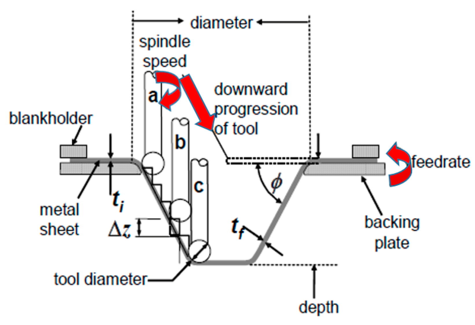
Figure 2.
Tensile test specimen dimensions (in mm).
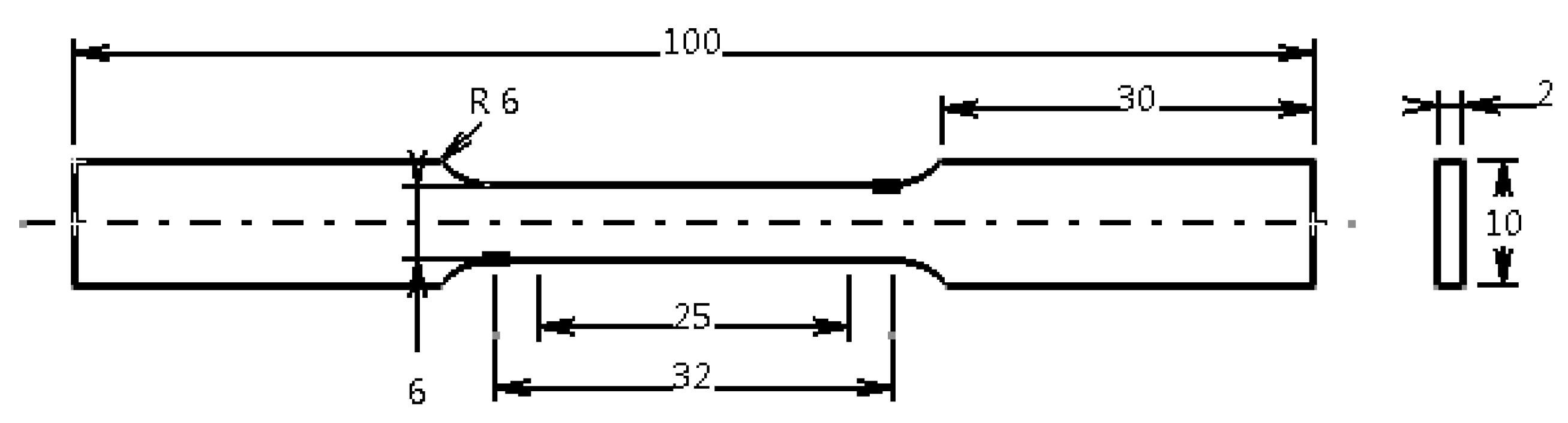
Figure 3.
True stress-strain curve of AA6061-T6.

Figure 4.
The forming jig with dynamometer.
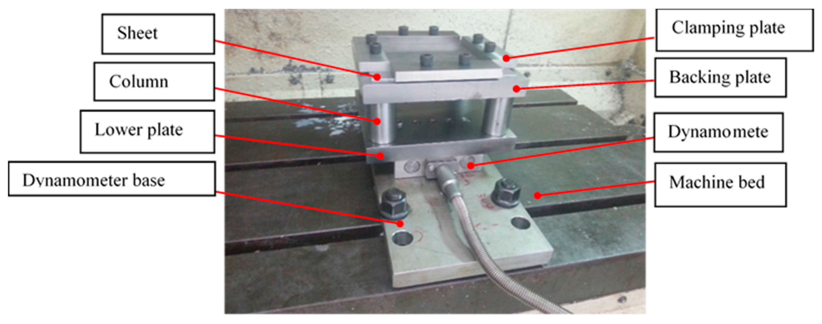
Figure 5.
The hemispherical-end forming tools (all dimensions in mm).
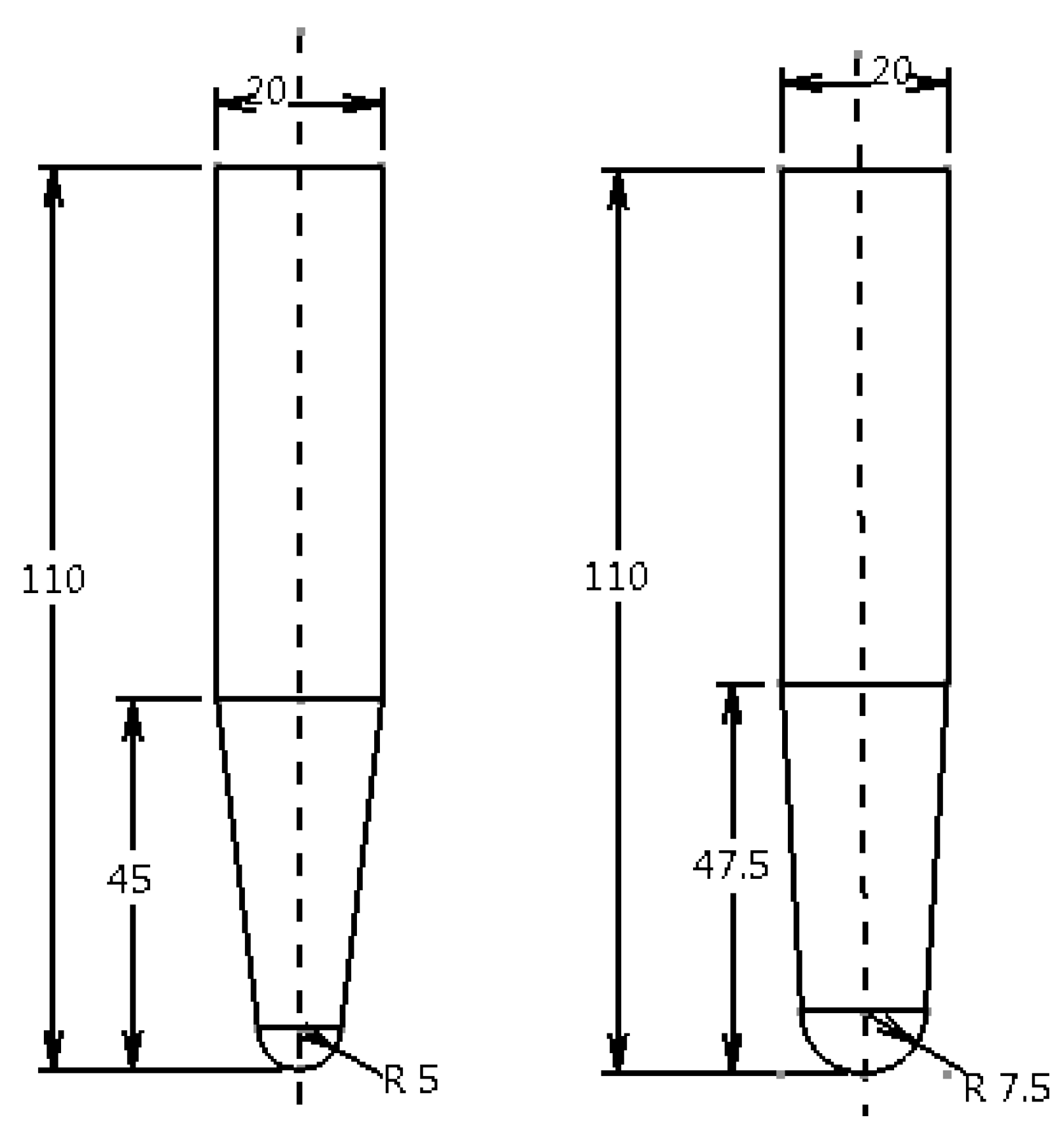
Figure 6.
The forming forces in SPIF (modified from [29]).
Figure 6.
The forming forces in SPIF (modified from [29]).

Figure 7.
Geometric illustration of the truncated cone profile (dimension in mm).
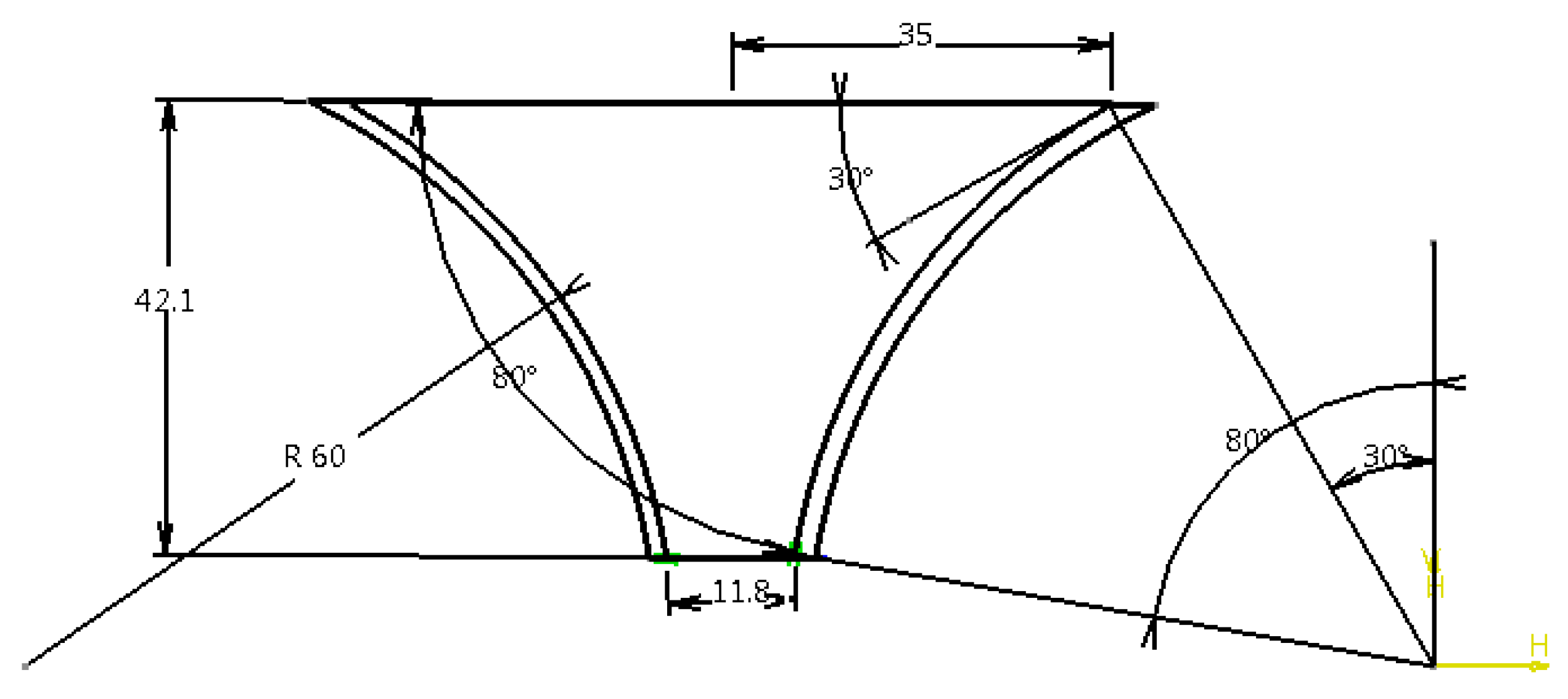
Figure 8.
Setting the tool trajectory parameters using CATIA software.

Figure 9.
Fracturing of sample at the end of the eight experiments via the SPIF (single-point incremental forming): (a) run 1; (b) run 2; (c) run 3; (d) run 4; (e) run 5; (f) run 6; (g) run 7; and (h) run 8.
Figure 9.
Fracturing of sample at the end of the eight experiments via the SPIF (single-point incremental forming): (a) run 1; (b) run 2; (c) run 3; (d) run 4; (e) run 5; (f) run 6; (g) run 7; and (h) run 8.


Figure 10.
Forming forces in the three directions for the cone produced with run 1.

Figure 11.
The forming forces in the three directions for the cone produced with run 2, (Fz-p max. = 3.8126 kN).
Figure 11.
The forming forces in the three directions for the cone produced with run 2, (Fz-p max. = 3.8126 kN).
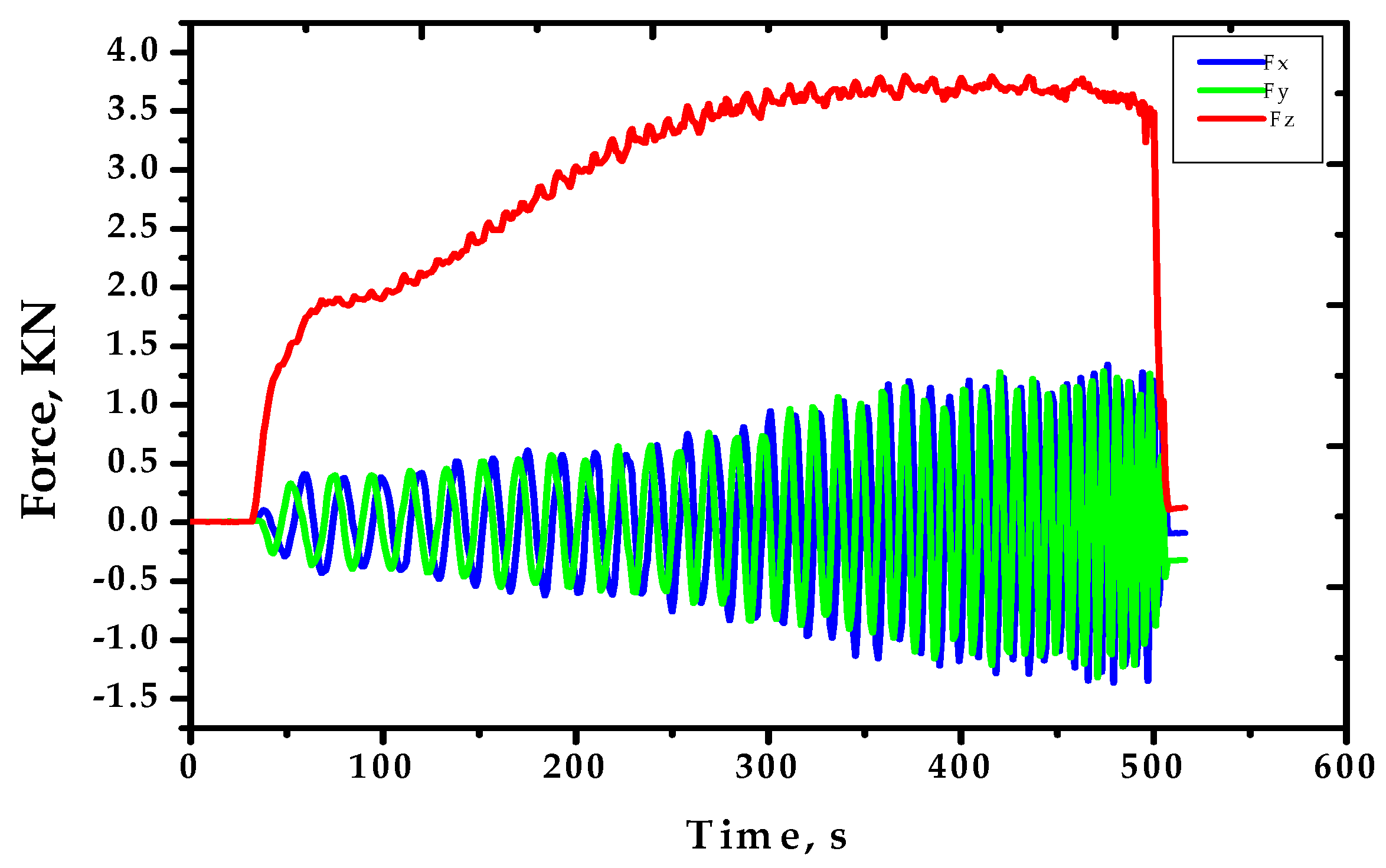
Figure 12.
Forming forces in the three directions for the cone produced with run 3.
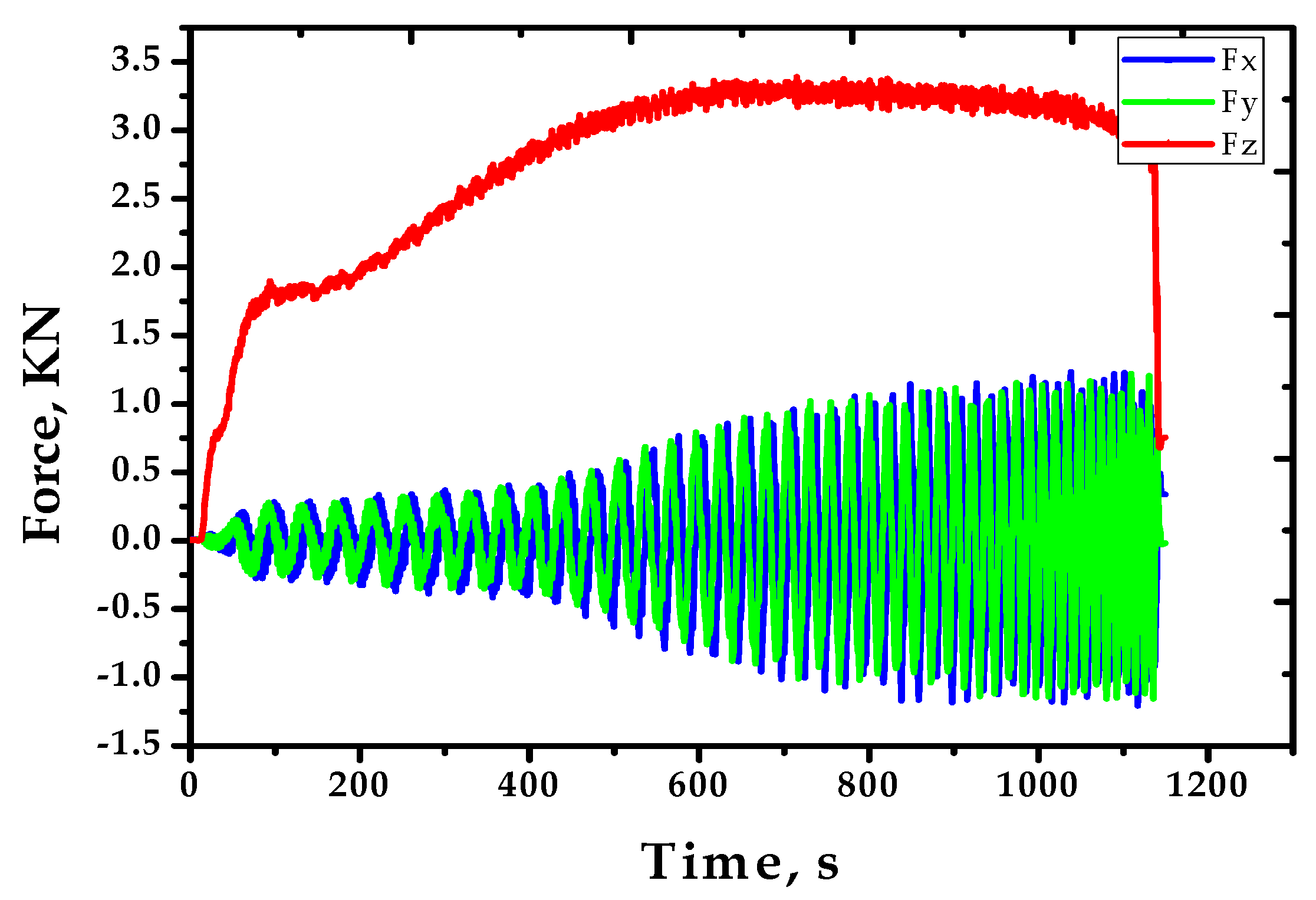
Figure 13.
Forming forces in the three directions for the cone produced with run 4.

Figure 14.
Forming forces in the three directions for the cone produced with run 5.

Figure 15.
Forming forces in the three directions for the cone produced with run 6, (Fz-p min. = 2.4513 kN).
Figure 15.
Forming forces in the three directions for the cone produced with run 6, (Fz-p min. = 2.4513 kN).

Figure 16.
Forming forces in the three directions for the cone produced with run 7.

Figure 17.
Forming forces in the three directions for the cone produced with run 8.

Figure 18.
The main effects plot for the Fz-p.

Figure 19.
The interactions plot for the Fz-p.

Figure 20.
Surface plot of the Fz-p against the feed rate and step size.

Figure 21.
Graphical representation of the interaction effects on the axial force.

Figure 22.
Normal distribution of the Fz-p.


Table 1.
Chemical composition (wt %) of the material.
| Material | Si | Fe | Cu | Mn | Mg | Cr | Ni | Zn | Ti | Al |
|---|---|---|---|---|---|---|---|---|---|---|
| AA6061-T6 | 0.52 | 0.19 | 0.27 | 0.07 | 0.91 | 0.1 | - | 0.02 | 0.01 | Bal. |
Table 2.
Process parameters and their levels.
| Parameter | Description | Level 1 | Level 2 | Level 3 | Level 4 |
|---|---|---|---|---|---|
| ω | Spindle speed (rpm) | 50 | 400 | 800 | 1200 |
| f | Feed rate (mm/min) | 250 | 500 | - | - |
| z | Step size (mm) | 0.2 | 0.5 | - | - |
| D | Tool tip diameter (mm) | 10 | 15 | - | - |
Table 3.
Orthogonal array L8 (41. 23) of the experimental runs.
| Run | ω (rpm) | f (mm/min) | z (mm) | D (mm) |
|---|---|---|---|---|
| 1 | 1 (50) | 1 (250) | 1 (0.2) | 1 (10) |
| 2 | 1 (50) | 2 (500) | 2 (0.5) | 2 (15) |
| 3 | 2 (400) | 1 (250) | 1 (0.2) | 2 (15) |
| 4 | 2 (400) | 2 (500) | 2 (0.5) | 1 (10) |
| 5 | 3 (800) | 1 (250) | 2 (0.5) | 1 (10) |
| 6 | 3 (800) | 2 (500) | 1 (0.2) | 2 (15) |
| 7 | 4 (1200) | 1 (250) | 2 (0.5) | 2 (15) |
| 8 | 4 (1200) | 2 (500) | 1 (0.2) | 1 (10) |
Table 4.
Forming forces in x, y, and z directions and the resultant forces at the peak point.
| Run | Max. Forces (kN) | Resultant Forces | |||
|---|---|---|---|---|---|
| Fx | Fy | Fz-p | Fxy | FR | |
| 1 | −0.60822 | 0.228577 | 3.29163 | 0.649748 | 3.355145 |
| 2 | 0.997925 | 0.700989 | 3.81836 | 1.219524 | 4.00838 |
| 3 | 0.240784 | 0.896912 | 3.41125 | 0.92867 | 3.5354 |
| 4 | −0.67658 | −0.31189 | 3.18024 | 0.745003 | 3.266337 |
| 5 | −0.19074 | 0.510559 | 2.91534 | 0.545023 | 2.965849 |
| 6 | 0.823669 | −0.08636 | 2.44781 | 0.828184 | 2.584118 |
| 7 | 0.665894 | 0.470276 | 3.04474 | 0.815214 | 3.151986 |
| 8 | 0.238037 | 0.513 | 2.60529 | 0.565536 | 2.665964 |
© 2017 by the authors. Licensee MDPI, Basel, Switzerland. This article is an open access article distributed under the terms and conditions of the Creative Commons Attribution (CC BY) license (http://creativecommons.org/licenses/by/4.0/).
Share and Cite
MDPI and ACS Style
Baharudin, B.T.H.T.; Azpen, Q.M.; Sulaima, S.; Mustapha, F. Experimental Investigation of Forming Forces in Frictional Stir Incremental Forming of Aluminum Alloy AA6061-T6. Metals 2017, 7, 484. https://doi.org/10.3390/met7110484
AMA Style
Baharudin BTHT, Azpen QM, Sulaima S, Mustapha F. Experimental Investigation of Forming Forces in Frictional Stir Incremental Forming of Aluminum Alloy AA6061-T6. Metals. 2017; 7(11):484. https://doi.org/10.3390/met7110484
Chicago/Turabian StyleBaharudin, B.T.H.T., Q.M. Azpen, Shamsuddin Sulaima, and F. Mustapha. 2017. "Experimental Investigation of Forming Forces in Frictional Stir Incremental Forming of Aluminum Alloy AA6061-T6" Metals 7, no. 11: 484. https://doi.org/10.3390/met7110484
Note that from the first issue of 2016, this journal uses article numbers instead of page numbers. See further details here.