Microstructure and Properties of Porous Si3N4/Dense Si3N4 Joints Bonded Using RE–Si–Al–O–N (RE = Y or Yb) Glasses


School of Materials Science and Engineering, Harbin Institute of Technology, Harbin 150001, China
*
Authors to whom correspondence should be addressed.
Metals 2017, 7(11), 500; https://doi.org/10.3390/met7110500
Submission received: 15 October 2017
/
Revised: 6 November 2017
/
Accepted: 9 November 2017
/
Published: 13 November 2017
(This article belongs to the Special Issue Diffusion Bonding and Brazing of Advanced Materials)
Abstract
:The joining of porous Si3N4 to dense Si3N4 ceramics has been successfully performed using mixed RE2O3 (RE = Y or Yb), Al2O3, SiO2, and α-Si3N4 powders. The results suggested that the α-Si3N4 powders partly transformed into β-SiAlON and partly dissolved into oxide glass to form oxynitride glass. Thus, composites of glass/β-SiAlON-ceramic formed in the seam of joints. Due to the capillary action of the porous Si3N4 ceramic, the molten glass solder infiltrated into the porous Si3N4 ceramic side during the joining process and formed the “infiltration zone” with a thickness of about 400 μm, which contributed to the heterogeneous distribution of the RE–Si–Al–O–N glasses in the porous Si3N4 substrate. In-situ formation of β-SiAlON in the seam resulted in a high bonding strength. The maximum bending strength of 103 MPa and 88 MPa was reached for the porous Si3N4/dense Si3N4 joints using Y–Si–Al–O–N and Yb–Si–Al–O–N glass solders, respectively.

1. Introduction
Dense silicon nitride (D-Si3N4) ceramics are considered to be important structure materials applicable for various industry parts [1] for its superior high temperature strength, thermal shock resistance, low thermal expansion coefficient, good wear, and corrosion resistance [2,3,4]. The porous Si3N4 (P-Si3N4) ceramics are emphasized for some engineering applications such as catalyst supports and gas filters due to its high mechanical strength, low dielectric constant, low density, and porous nature [5,6,7,8]. In the present work, the porous Si3N4 ceramics were tried to join to the dense Si3N4 to combine the performance advantages of both the materials. In order to widen their applications, reliable joining techniques are essential, among which the brazing and diffusion bonding techniques are especially popular for the ceramics [9,10]. However, large residual stress inevitably resided in the joint after brazing or diffusion bonding due to the mismatch of the coefficient of thermal expansion (CTE) between the metallic layers and the ceramic materials [11,12,13].
Currently, the bonding of ceramics with oxide or oxynitride glass adhesives has been successful [14,15,16,17]. Since the sintering aids contribute to excellent bonding between Si3N4 grains during the synthesis process, they should also be applicable for the joining of bulk materials. In the dense Si3N4 ceramics, conventional sintering aids such as Y2O3, Al2O3, MgO, and CaO have been widely used as the joint interlayers [18,19,20]. Walls et al. [21,22] used composite β-Sialon-glass adhesives (a mixture of Y2O3, SiO2, Al2O3, and α-Si3N4) to join Sialon ceramics. Their results suggest that the α-Si3N4 reacted to form β-Sialon, which had an acicular nature to reinforce the joint. However, these studies have all focused on the joining of dense silicon nitride ceramics.
In the present work, porous Si3N4 ceramic was firstly bonded to dense Si3N4 using RE (Y2O3 or Yb2O3)-Al2O3-SiO2-Si3N4 mixtures, which in-situ formed a high proportion of β-SiAlON in the seam; the influence of bonding parameters and solder composition on the interfacial morphology and joint strengths were studied. In addition, the influence of oxynitride glasses on the microstructure of Si3N4 substrates was also investigated. Finally, the infiltration behavior of the glass filler in the porous Si3N4 substrate was revealed.
2. Materials and Methods
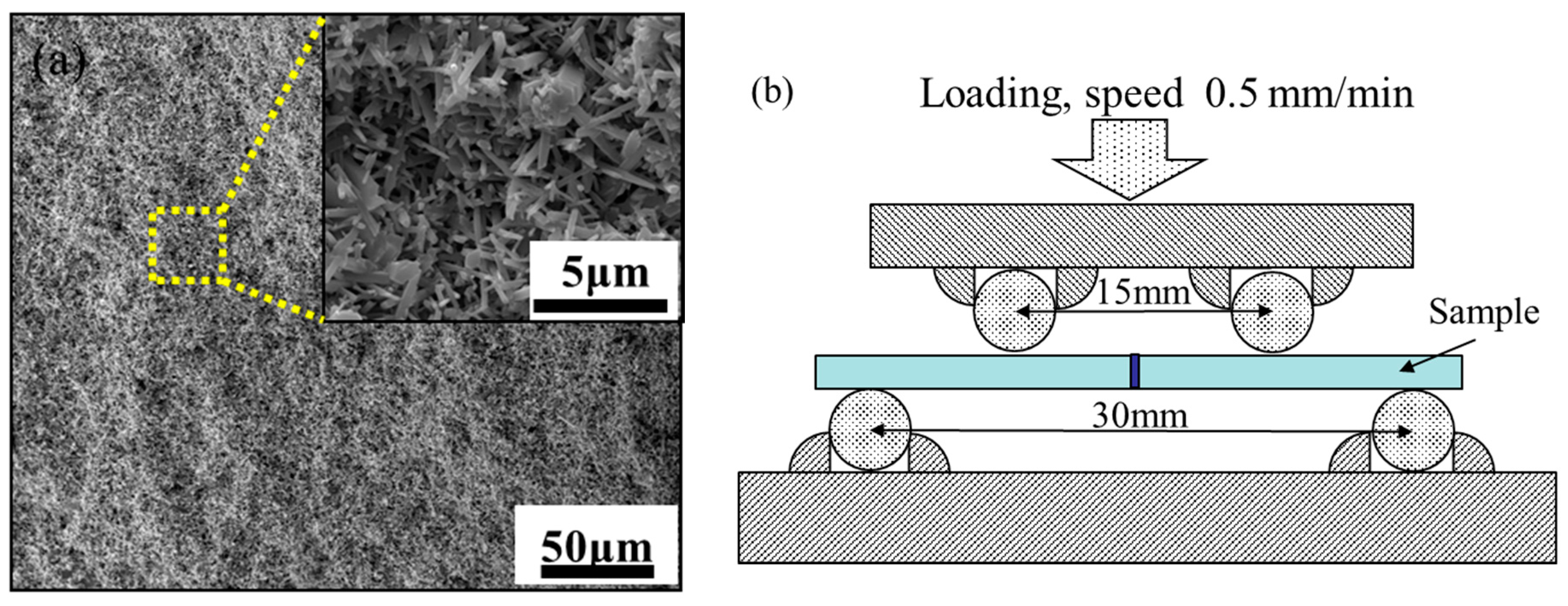
The porous Si3N4 ceramics (Shandong Industrial Ceramics Research & Design Institute Co., Ltd., Zibo, China) selected in this study with a porosity of approximately 47% were prepared via gas pressure sintering (GPS). The dense Si3N4 ceramics (Shandong Industrial ceramics Research & Design Institute Co., Ltd., Zibo, China) were pressurelessly sintered and contained a small percentage of Al2O3 and Y2O3 as sintering aids. The four-point bending strengths of the porous Si3N4 and dense Si3N4 were 142 MPa and 486 MPa, respectively. Figure 1a shows the morphology of the porous Si3N4 substrate with elongated grains, which were randomly connected in three dimensions.
The raw ceramics ingots were cut into blocks with the dimensions of 4 mm × 4 mm × 4 mm to be joined for microstructural analysis, and 3 mm × 4 mm × 18 mm to be joined for flexural strength testing. The working surfaces were ground using waterproof abrasive 1000 grit paper, followed by a mechanical polish to 1 μm.
The compositions of the glass solders (Y–Si–Al–O–N and Yb–Si–Al–O–N glasses) adopted in the present work are listed in Table 1. The powders were manually ground in ethanol for 3 h using an agate mortar to obtain a homogeneous slurry. Afterwards, the slurry was dried, the mixture was cold-pressed under 6 MPa to obtain a slice of 600 μm in thickness using a tablet machine. The porous Si3N4 and dense Si3N4 rectangular specimens together with a solder slice were assembled in a sandwich structure. The assembly was placed under a modest uniaxial pressure of 0.6 MPa to ensure good contact between the solder and silicon nitride ceramics during the joining process. The joining experiment was conducted in a graphite furnace with a wide range of bonding temperatures (1550–1650 °C) for 30 min. The pressure of N2 atmosphere was kept at 0.04 MPa throughout the joining process. Four-point bending strengths were measured with an upper span of 15 mm and a lower span of 30 mm using a universal testing machine (Instron 5569, Instron Corporation, Canton, MA, USA) at a speed of 0.5 mm/min. The test jig geometry used for bend testing is shown in Figure 1b. For each set of experimental data, five samples were used to average to joint strength. Scanning electron microscope (SEM) images were collected with a FEI Quanta 200FEG instrument (FEI Corporation, Hillsporo, OR, USA) at accelerating voltages of 20 kV with an energy dispersive spectroscope (EDS, OXFORD Instruments, Oxford, UK) system. The phases in the joints were identified by X-ray diffraction (XRD, PANalytical B.V., Almelo, Netherlands) with Cu Kα radiation at a scanning step of 0.05° and a scanning rate of 5°/min.
3. Results and Discussion
3.1. Characterization of P-Si3N4/RE(Y or Yb)-SiAlON/D-Si3N4 Joints
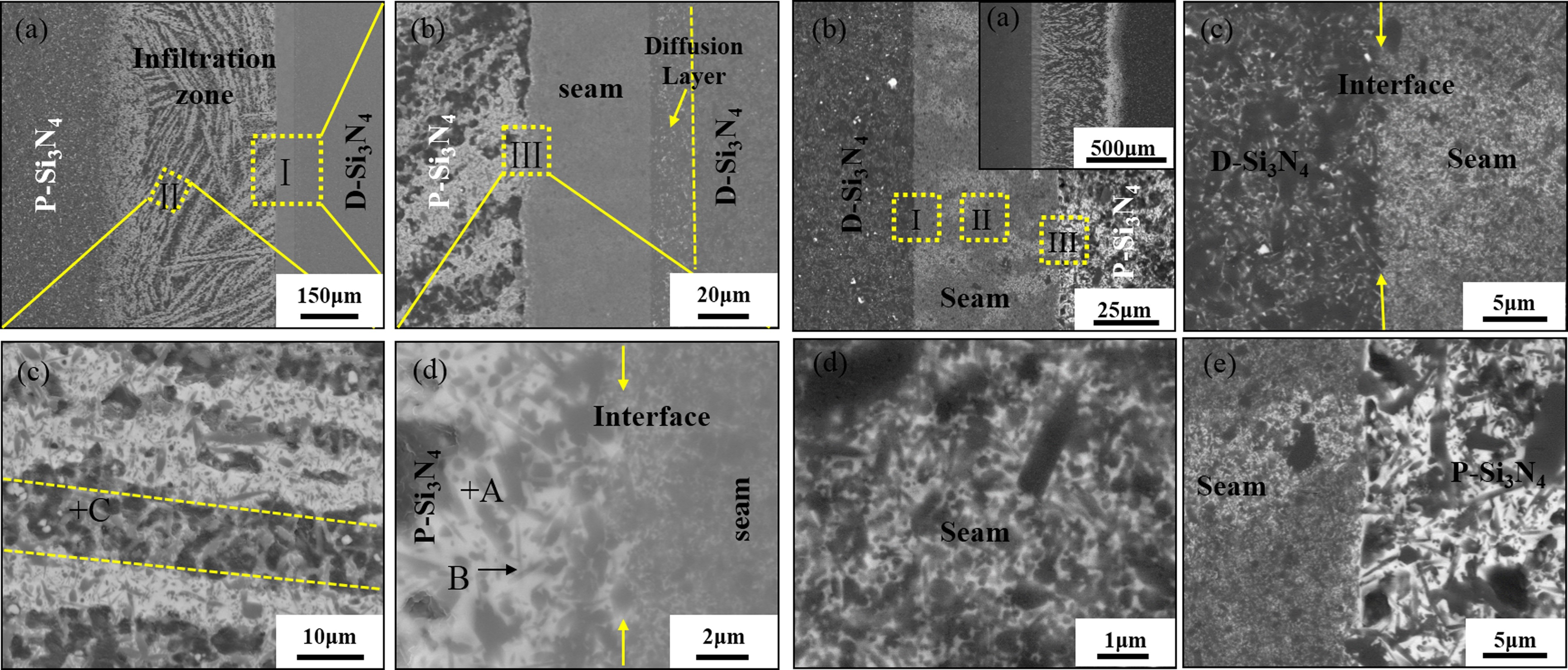
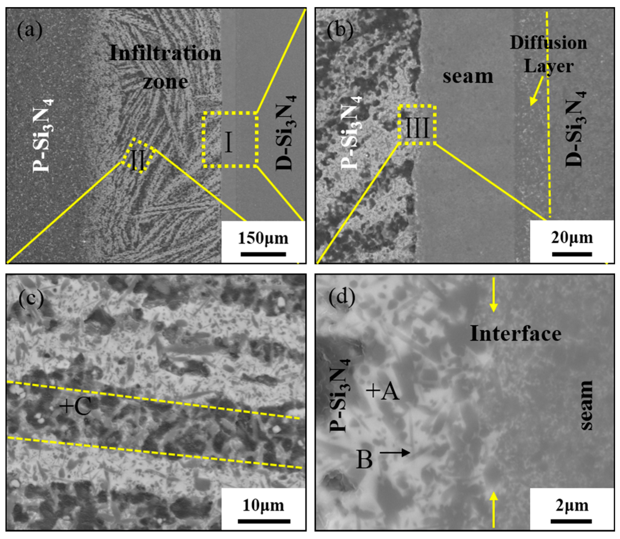
Figure 2 shows the back-scattered SEM images of the joint bonded at 1650 °C for 30 min using a Y-SiAlON glass solder. The joint was crack-free, compact, and uniform. The joint can be divided into three regions: the infiltration zone (on the porous Si3N4 substrate side), the seam zone, and the diffusion zone (on the dense Si3N4 substrate side). An infiltration zone with a width of about 450 μm can be observed in the porous Si3N4 substrate in Figure 2a, as can white ribbon-like structures distributed in the infiltration zone. In order to investigate the microstructure in detail, the microstructures of Zone I were highly magnified, and they are shown in Figure 2b, which shows the three behaviors of the molten glass. One is the diffusion into dense Si3N4 along the grain boundary to form a diffusion layer. Another is the infiltration into the porous Si3N4, and the densification of the residual solder in the seam. The ribbon-like structures were virtually composed of a black needle-like phase and a white glass phase in Zone II. In addition, in order to be observed, the direction of the yellow dashed frame (Zone II) is rotated and magnified in Figure 2c. The residual skeleton structure of the porous Si3N4 ceramics can be seen between the two labeled lines. The EDS results of the spots marked in the figure are listed in Table 2. It can be concluded that the white substrate Phase A was Y-SiAlON glass. In addition, the needle-like phase β-SiAlON grains (Phase B) with a fine structure formed in the infiltration zone (Figure 2d). Therefore, it was deduced that the molten Y-SiAlON glass solder infiltrated into the pores of the porous Si3N4 during the joining process, contributed to the transformation of the original α-Si3N4 to β-SiAlON in the infiltration zone. Simultaneously, the residual glass solder in the seam was turned into composites of glass/β-SiAlON-ceramic. The α- to β-phase transformation is consistent with the findings in other literature about the joining of dense Si3N4-based ceramics [22,23].
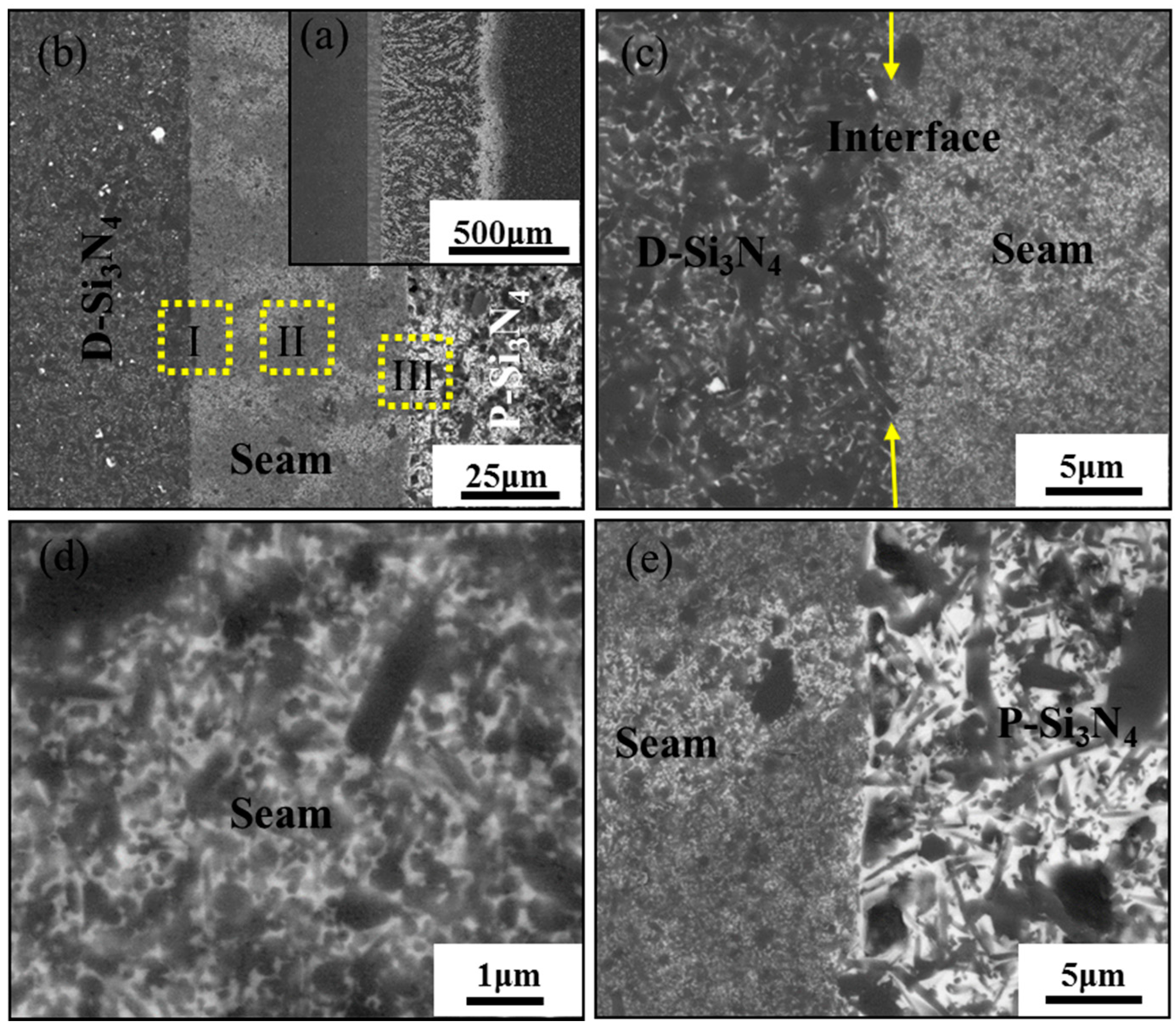
Figure 3a,b show the morphologies of the P-Si3N4/D-Si3N4 joints using Yb-SiAlON glass solder. No cracks resulting from thermal expansion mismatch appeared at the interfaces between the seam and ceramic substrates. It is also noted that the ribbon-like infiltration zone at about 500 μm was also formed on the porous Si3N4 ceramic side. Figure 3c shows the magnified morphology of the interface between the seam and the dense Si3N4, where an interlocked microstructure can be observed at the interface, which was mainly attributed to the concentration gradient between the intergranular phase in the matrix and the glass solder composition. It has been reported that the Yb–Si–Al–O liquid is able to transform into Yb–Si–Al–O–N liquid system due to the dissolution of α-Si3N4 during the joining process [24], and the undissolved α-Si3N4 may be converted to β-SiAlON above a temperature of 1500 °C via dissolution-precipitation or act as a heterogeneous core. Diffusion of the molten glass from the joining interface into the dense Si3N4 substrates was obvious, indicating that reaction occurs at the liquid/solid interface. Composites of glass/β-SiAlON-ceramic formed in the seam (Figure 3d). Figure 3e shows that most of molten glass penetrated into the porous Si3N4 through its connected pore. The porous nature of the porous Si3N4 was destroyed, while it contributed to the formation of a dense joint interface.
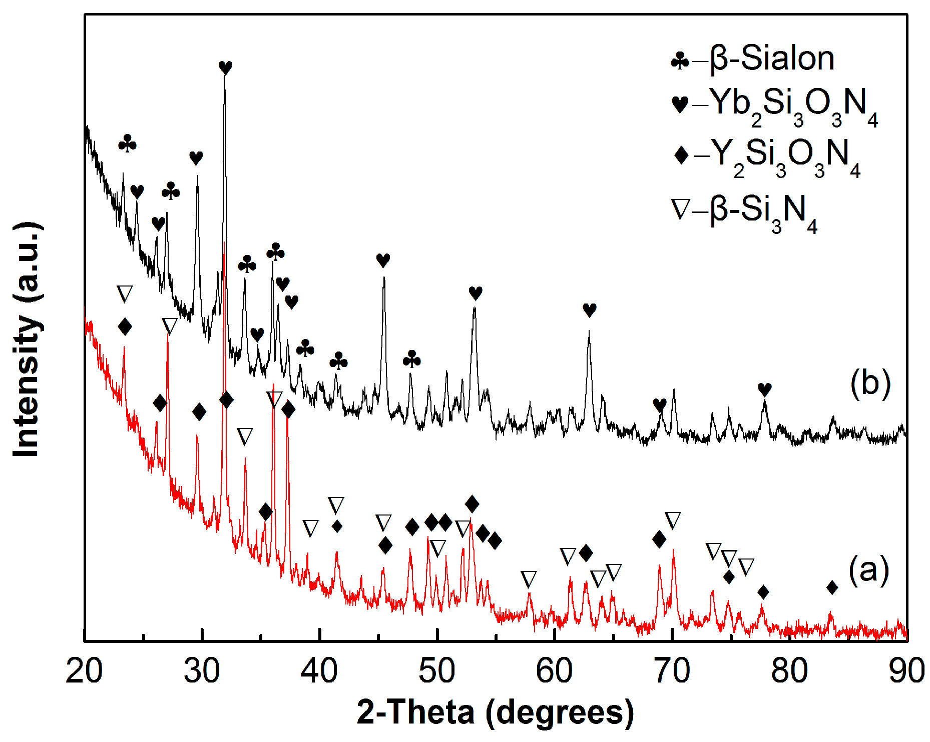
Afterwards, the XRD patterns of the joints using two different glass solders are indicated in Figure 4. It is proved that α-Si3N4 transfers to β-SiAlON during the bonding process. In addition, the crystallization of Y2Si3O3N4 and Yb2Si3O3N4 phases were detected in these two different joints, respectively.
3.2. Bending Strength of the Joints
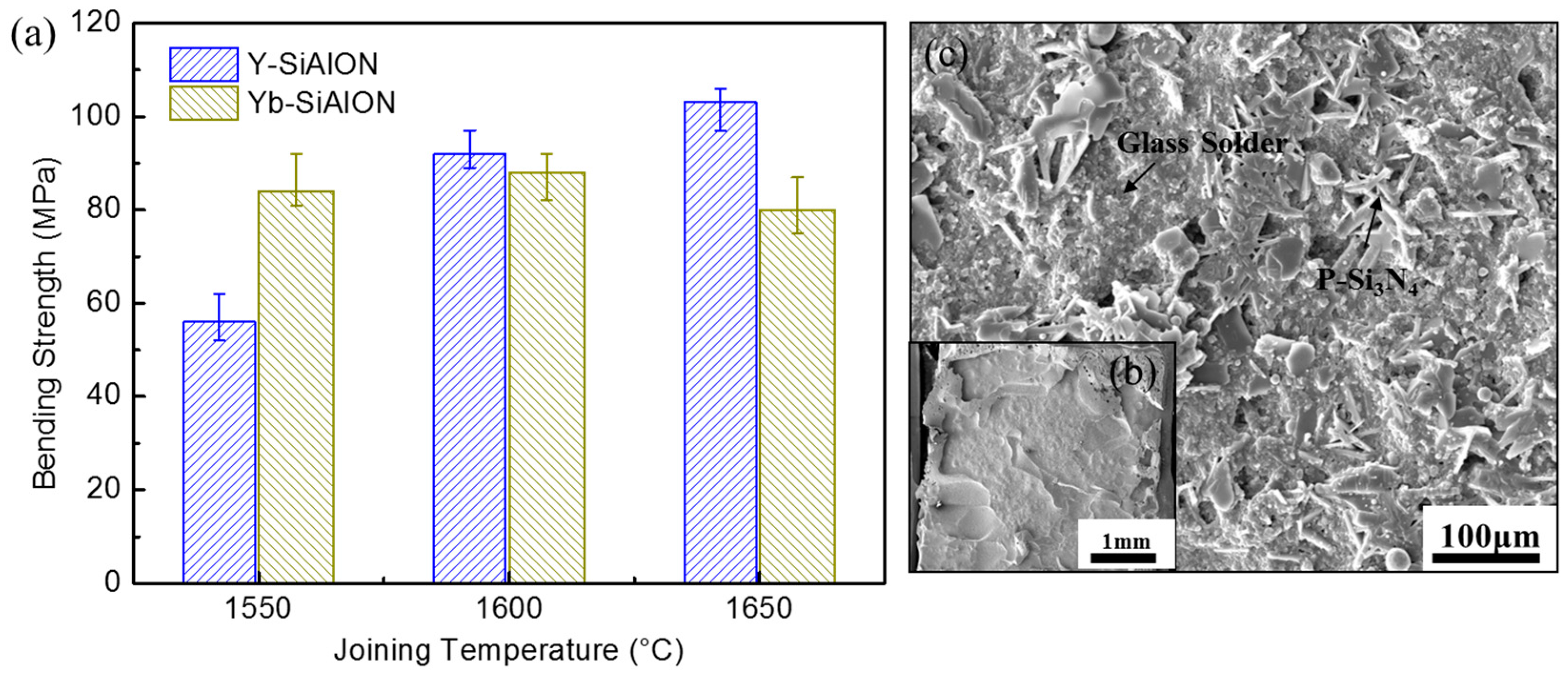
Figure 5 shows the bending strengths of the P-Si3N4/D-Si3N4 joints using RE–Si–Al–O–N (RE = Y or Yb) glasses and the typical fracture morphology. When the Y-SiAlON glass was applied, the room temperature bending strength of the joints were significantly improved with the increase of bonding temperature, from 56 MPa at 1550 °C to 103 MPa at 1650 °C. The maximum bending strength of the bonding joints accounts for 73% of the bending strength of the porous Si3N4 substrate. Two factors, including the formation of the interlocking acicular β-SiAlON grain network and pore-free interface, were thought to be responsible for the high strengths of the joints [21]. When the Yb-SiAlON glass was used, a slight change in performance was found, and a maximum strength of 88 MPa was achieved at 1600 °C, which was 62% of the bending strength of the porous Si3N4 substrate. Fracture analysis suggested that all the joints broke on the porous Si3N4 substrate side. Therefore, a typical morphology of the joint fracture was selected and is shown in Figure 5b. Figure 5c displays the local magnified region of the fracture surface, and a mixed fracture path of glass solder and rodlike Si3N4 can be seen. Thus, the fracture location was in the infiltration zone of the porous Si3N4 substrate. Though the infiltration of the glass solder can lead to the bonding of the porous Si3N4 and the seam, it can also break the skeletal structure of the porous Si3N4 substrate, as mentioned above. Thus, it is expected that the joining can be improved by optimizing the infiltration of the glass solders in a future work. A detailed morphology of the joints and corresponding illustration is provided in the following section.
3.3. Effect of Bonding Temperatures on Microstructure Evolution of the Joints
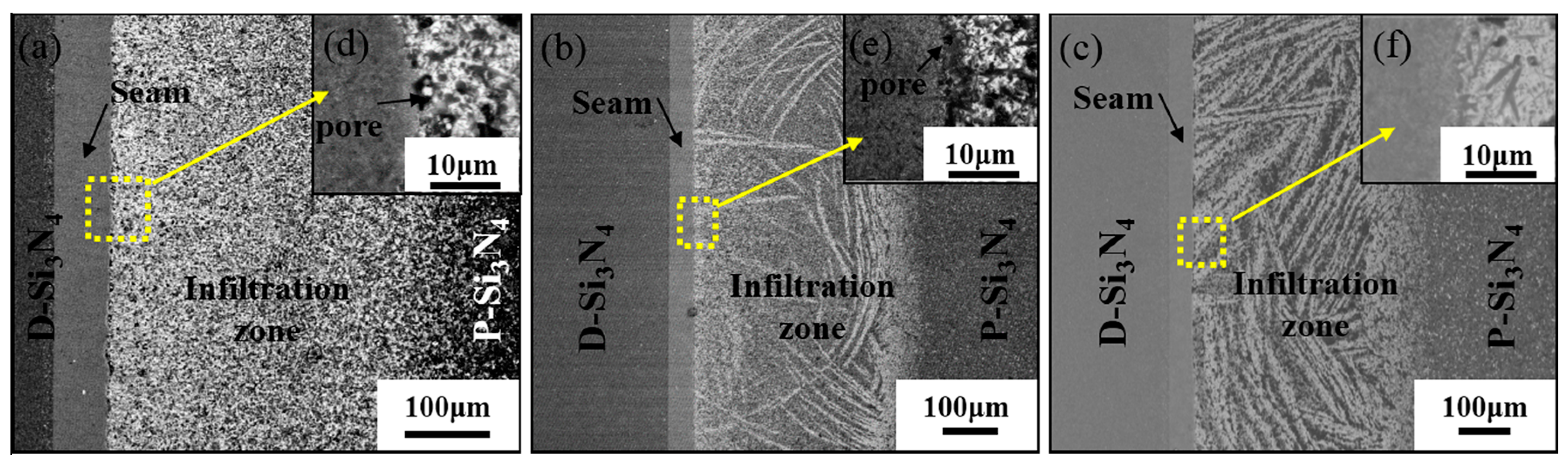
Figure 6 displays the images of the P-Si3N4/D-Si3N4 joints bonded by Y-SiAlON glass solder at different temperatures for 30 min. Although the widths of the infiltration zones were 426 μm, 428 μm, and 436 μm, which changed slightly as the bonding temperature increased, many white ribbon-like “flowing channels” formed in the infiltration zone when joined at 1600 °C and 1650 °C. The heterogeneous solder glass diffused and solidified in the porous Si3N4 accounts for the formation of the morphology. Therefore, it can be deduced that the infiltration zone contains a white Y-SiAlON glass phase, which was embedded with fine-grain β-Sialon and β-Si3N4. Remnant pores in the interface of the infiltration zone/interlayer (joining at 1550 °C and 1600 °C) can be observed in Figure 6d,e. However, when the temperature was as high as 1650 °C (Figure 6f), the white Y-SiAlON glass diffused into the porous Si3N4 substrate and filled the pores of the surface to form a continuous interface. This improvement might be attributed to the low viscosity of the glass at 1650 °C. Therefore, the bonding strength was effectively enhanced.
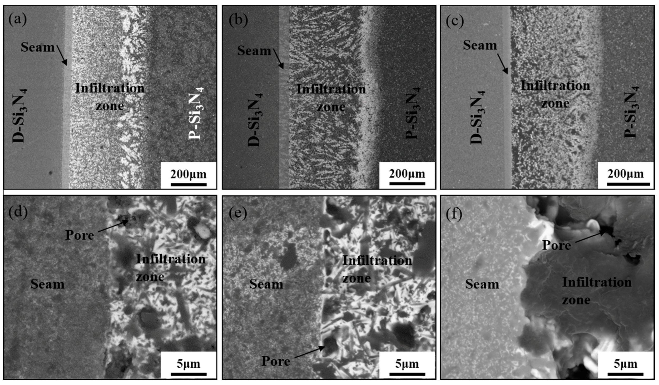
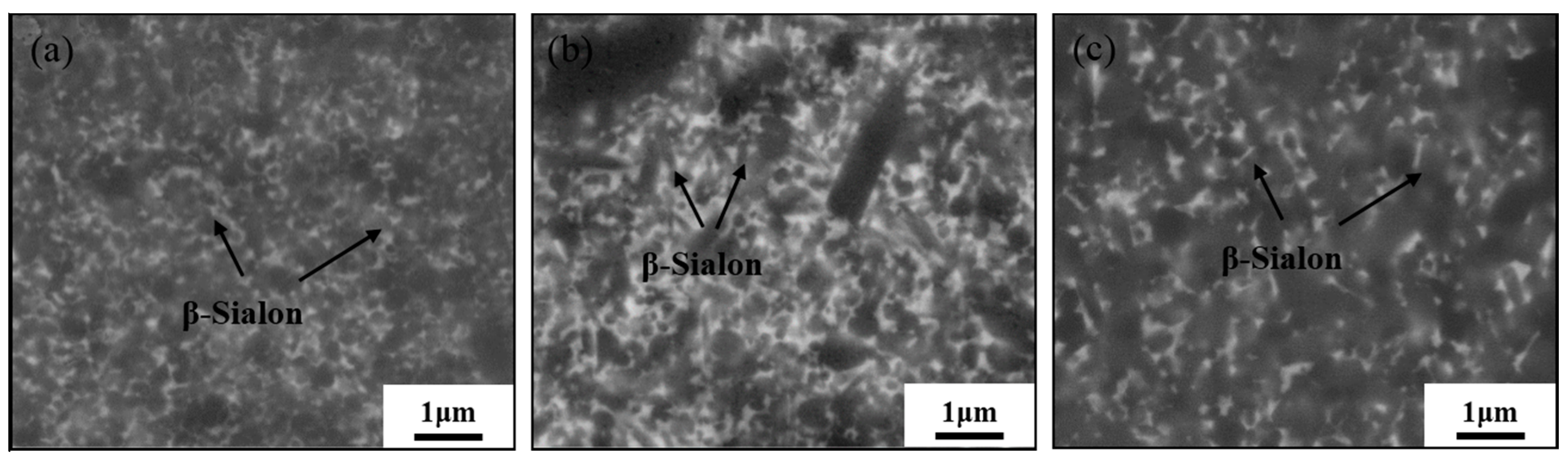
A similar characterization of the joints using Yb-SiAlON glass solder at different temperatures is displayed in Figure 7. In addition, measurement of the thicknesses of the infiltration zones was performed under SEM, and the thicknesses were determined to be 433 μm, 512 μm, and 427 μm at 1550 °C, 1600 °C, and 1650 °C, respectively. The distribution of white oxynitride glass in the infiltration zones was inhomogeneous. The morphologies of the interface between the infiltration zone and the seam bonded at different temperatures are displayed from Figure 7d to Figure 7f. In the figures, remnant pores can be observed at the interface. This may be attributed to the infiltration of liquid glass into the porous Si3N4 substrate. As a result, during cooling, the glass solder was not provided promptly for filling the interface between porous substrate and seam, which was similar to the use of Y-SiAlON glass solder (Figure 6d,e). If a continuous interface was formed between the porous substrate and seam (Figure 6f), the bonding strength would improve. Therefore, it is reasonable to assume the lower bonding strengths of these joints. Figure 8 shows the magnified morphologies of the seam zones at different temperatures. It is worth pointing out that the grain shapes of β-SiAlON (submicrometer diameter) apparently grow with the increase in bonding temperature. The microstructure of the seam zone similar to that of the dense Si3N4 ceramic suggests that the joining process followed the mechanism of the ceramic sintering process: oxide melt formed, silicon nitride dissolved to form oxynitride glasses, and the β-phase then nucleated. Nevertheless, most of the glass liquid would infiltrate into the porous Si3N4 substrate, and the redundant glass formed the intergranular phase in the joint, which is different from the process of sintering Si3N4 ceramics.
Above all, the microstructural evolution of the P-Si3N4/D-Si3N4 joints using RE–Si–Al–O–N (RE = Y or Yb) oxynitride glasses could be described as follows: the glass RE2O3-Al2O3-SiO2 system began to melt at a eutectic temperature, which is approximately 1350 °C in this system [21], and densified the joint during the joining process. With the temperature rose, the glass liquid in the seam began to flow and even infiltrate into the porous Si3N4 ceramic, resulting in the reduction of the glass liquid in the seam. When the temperature further rose up to bonding temperature and as the temperature was maintained, the α-Si3N4 powders dissolved into the liquid to form RE–Si–Al–O–N glasses. The infiltration zone formed on the porous Si3N4 substrate side due to its porous microstructure and the flowability of the oxynitride glass solders. At different joining temperatures, the morphologies of the infiltration zone were different, which may be closely related to the viscosity of the liquid glasses and the type of rare earth elements. This has yet to be further studied in subsequent research work. Meanwhile, on the dense Si3N4 substrate side, it was observed that an interlocked microstructure of the interface was produced due to the diffusion of liquid phase driven by concentration gradient. The strength of the joint would improve because of the increased local density of the interface region, and glass solders could also be used to bond the porous Si3N4 ceramics after sealing their surface pores.
4. Conclusions
In the present work, joining of Si3N4 ceramics has been successfully performed using RE–Si–Al–O–N (RE = Y or Yb) glass solders, at joining temperatures of 1550 °C, 1600 °C, and 1650 °C, each held for 30 min. The results lead to the following conclusions:
- (1)
- RE–Si–Al–O–N (RE = Y or Yb) glass solders were successfully used to bond porous Si3N4 to dense Si3N4 ceramics at high temperature. The maximum bending strengths of the joints bonded using Y-SiAlON and Yb-SiAlON glass solders were measured to be 103 MPa and 88 MPa. The bending strength of the joints accounts for 73% and 62% of the bending strength of the porous Si3N4 substrate, respectively.
- (2)
- The microstructure of such joints consisted of a diffusion zone, an infiltration zone, and a seam zone. During the bonding process, an interlocked interface formed on the dense Si3N4 substrate side, and an infiltration zone arose on the porous Si3N4 substrate side. In the seam zone, α-Si3N4 partly transformed into β-SiAlON to form β-SiAlON-glass composite.
With the increase in bonding temperature, the microstructure evolution of the joint was dominated by the following factors: (i) The flowability of liquid oxyniride glass allowed for the rapid bonding of the ceramic substrates; (ii) The capillary action of the porous Si3N4 substrate contributed to the infiltration of glass solders. A small amount of infiltration is good for sealing porous Si3N4, while excessive infiltration may cause pores at the interface of the porous Si3N4 substrate side and weaken the bonding strength.
Acknowledgments
This work was financially supported by the National Natural Science Foundation of China (NSFC) under Grant No. 51621091 and U1537206.
Author Contributions
The experiments were carried out by Ling Li, Liangbo Sun, and Xinhua Wang. Ling Li, Jie Zhang, and Chunfeng Liu conceived and designed the experiments. Ling Li, Liangbo Sun, and Xuanzhi Wang analyzed the data. The manuscript was written by Ling Li and revised by Liangbo Sun, Jie Zhang, and Chunfeng Liu.
Conflicts of Interest
The authors declare no conflict of interest.
References
- Riley, F.L. Silicon nitride and related materials. J. Am. Ceram. Soc. 2000, 83, 245–265. [Google Scholar] [CrossRef]
- Liu, X.J.; Huang, Z.Y.; Ge, Q.M.; Sun, X.W.; Huang, L.P. Microstructure and mechanical properties of silicon nitride ceramics prepared by pressureless sintering with MgO-Al2O3-SiO2 as sintering additive. J. Eur. Ceram. Soc. 2005, 25, 3353–3359. [Google Scholar] [CrossRef]
- Krstic, Z.; Krstic, V.D. Silicon nitride: The engineering material of the future. J. Mater. Sci. 2011, 47, 535–552. [Google Scholar] [CrossRef]
- Hou, X.; Wang, E.; Li, B.; Chen, J.; Chou, K.-C. Corrosion behavior of porous silicon nitride ceramics in different atmospheres. Ceram. Int. 2017, 43, 4344–4352. [Google Scholar] [CrossRef]
- Kawai, C.; Yamakawa, A. Effect of porosity and microstructure on the strength of Si3N4: Designed microstructure for high strength, high thermal shock resistance, and facile machining. J. Am. Ceram. Soc. 1997, 80, 2705–2708. [Google Scholar] [CrossRef]
- Wang, H.; Yu, J.; Zhang, J.; Zhang, D. Preparation and properties of pressureless-sintered porous Si3N4. J. Mater. Sci. 2010, 45, 3671–3676. [Google Scholar] [CrossRef]
- Wang, C.; Wang, H.; Qiao, R.; Zhang, C.; Chen, L. Fabrication and thermal shock resistance of β-Si3N4-based environmental barrier coating on porous Si3N4 ceramic. Ceram. Int. 2016, 42, 14222–14227. [Google Scholar] [CrossRef]
- Wang, C.; Fan, L.; Fan, J.; Zhang, D.; Wang, H. Effect of spraying power on microstructure and properties of supersonic plasma sprayed Al2O3 coating on porous Si3N4 substrate. J. Alloys Compd. 2013, 559, 152–157. [Google Scholar] [CrossRef]
- Zhuang, Y.L.; Lin, T.S.; Wang, S.J.; He, P.; Sekulic, D.P.; Jia, D.C. Microstructural and mechanical properties of porous Si3N4 carbon coated ceramic brazed with a cobalt-silicon filler. J. Eur. Ceram. Soc. 2017, 37, 3293–3301. [Google Scholar] [CrossRef]
- He, Y.; Zhang, J.; Li, X. Characterization of the Si3N4/Si3N4 joints fabricated using particles modified braze. Mater. Sci. Eng. A 2014, 616, 107–115. [Google Scholar] [CrossRef]
- Wang, T.; Ivas, T.; Lee, W.; Leinenbach, C.; Zhang, J. Relief of the residual stresses in Si3N4/Invar joints by multi-layered braze structure-experiments and simulation. Ceram. Int. 2016, 42, 7080–7087. [Google Scholar] [CrossRef]
- Li, J.; Liu, L.; Wu, Y.; Li, Z.; Zhang, W.; Hu, W. Microstructure of high temperature Ti-based brazing alloys and wettability on SiC ceramic. Mater. Des. 2009, 30, 275–279. [Google Scholar] [CrossRef]
- Lemusruiz, J.; Leonpatino, C.; Aguilarreyes, E. Interface behaviour during the self-joining of Si3N4 using a Nb-foil interlayer. Scr. Mater. 2006, 54, 1339–1343. [Google Scholar] [CrossRef]
- Xie, R.; Huang, L.; Fu, X. Bond strength and microstructural investigation on Si3N4/Si3N4 joint bonded with glass-ceramic. J. Mater. Sci. Lett. 1998, 17, 761–763. [Google Scholar] [CrossRef]
- Xie, R.; Huang, L.; Fu, X.; Chen, Y. Effects of adhesive composition on bond strength of joined silicon nitride ceramics. J. Eur. Ceram. Soc. 1998, 18, 901–905. [Google Scholar] [CrossRef]
- Xie, R.; Huang, L.; Chen, Y.; Fu, X. Effects of chemical compositions of adhesive and joining processes on bond strength of Si3N4/Si3N4 joints. Ceram. Int. 1999, 25, 101–105. [Google Scholar] [CrossRef]
- Gopal, M.; Sixta, M.; De Jonghe, L.; Thomas, G. Seamless joining of silicon nitride ceramics. J. Am. Ceram. Soc. 2001, 84, 708–712. [Google Scholar] [CrossRef]
- Gopal, M.; De Jonghe, L.C.; Thomas, G. Silicon nitride joining using rare-earth reaction sintering. Scr. Mater. 1997, 36, 455–460. [Google Scholar] [CrossRef]
- Iwamoto, N.; Umesaki, N.; Haibara, Y. Silicon nitride joining with glass solder in the system CaO-SiO2-TiO2. Int. J. High Technol. Ceram. 1987, 3, 176. [Google Scholar] [CrossRef]
- Johnson, S.M.; Rowcliffe, D.J. Mechanical properties of joined silicon nitride. J. Am. Ceram. Soc. 1985, 68, 468–472. [Google Scholar] [CrossRef]
- Walls, P.A.; Ueki, M. Mechanical properties of β-sialon ceramics joined using composite β-sialon-glass adhesives. J. Am. Ceram. Soc. 1995, 78, 999–1005. [Google Scholar] [CrossRef]
- Walls, P.A.; Ueki, M. Joining sialon ceramics using composite β-sialon-glass adhesives. J. Am. Ceram. Soc. 1992, 75, 2491–2497. [Google Scholar] [CrossRef]
- Weldon, L.M.; Hampshire, S.; Pomeroy, M.J. Joining of ceramics using oxide and oxynitride glasses in the Y-Sialon system. J. Eur. Ceram. Soc. 1997, 17, 1941–1947. [Google Scholar] [CrossRef]
- Saito, N.; Kai, K.; Furusho, S.; Nakashima, K.; Mori, K.; Shimizu, F. Properties of nitrogen-containing yttria-Alumina-Silica melts and glasses. J. Am. Ceram. Soc. 2003, 86, 711–716. [Google Scholar] [CrossRef]
Figure 1.
Characterization of the porous Si3N4 ceramic (a) and test jig geometry used for four-point bend testing (b).
Figure 1.
Characterization of the porous Si3N4 ceramic (a) and test jig geometry used for four-point bend testing (b).

Figure 2.
Backscattered SEM images of (a) the joint between P-Si3N4 and D-Si3N4 using Y-SiAlON glass solder at 1650 °C for 30 min. (b) The magnified morphology of Zone I, (c) the magnified morphology of Zone II, and (d) the magnified morphology of Zone III, respectively.
Figure 2.
Backscattered SEM images of (a) the joint between P-Si3N4 and D-Si3N4 using Y-SiAlON glass solder at 1650 °C for 30 min. (b) The magnified morphology of Zone I, (c) the magnified morphology of Zone II, and (d) the magnified morphology of Zone III, respectively.

Figure 3.
Joint of P-Si3N4/D-Si3N4 using Yb-SiAlON glass solder at 1600 °C for 30 min: (a,b) low and high magnification, (c) the magnified micrograph of the interface between D-Si3N4 and the seam (Zone I), (d) the magnified micrograph of the seam (Zone II), and (e) the magnified micrograph of the interface between P-Si3N4 and the seam (Zone III), respectively.

Figure 4.
XRD (X-ray diffraction) patterns taken from the filler area of the ceramics joints bonded by (a) Y-SiAlON and (b) Yb-SiAlON, respectively.
Figure 4.
XRD (X-ray diffraction) patterns taken from the filler area of the ceramics joints bonded by (a) Y-SiAlON and (b) Yb-SiAlON, respectively.

Figure 5.
The function of the bending strength of the P-Si3N4/D-Si3N4 joints as bonding temperatures (a), the fracture surface of the joint bonded with Y-SiAlON at 1650 °C (b), and the magnified micrograph of the fracture surface (c).
Figure 5.
The function of the bending strength of the P-Si3N4/D-Si3N4 joints as bonding temperatures (a), the fracture surface of the joint bonded with Y-SiAlON at 1650 °C (b), and the magnified micrograph of the fracture surface (c).

Figure 6.
The microstructure of P-Si3N4/Y-SiAlON/D-Si3N4 joints bonding at (a,d) 1550 °C, (b,e) 1600 °C, and (c,f) 1650 °C for 30 min.
Figure 6.
The microstructure of P-Si3N4/Y-SiAlON/D-Si3N4 joints bonding at (a,d) 1550 °C, (b,e) 1600 °C, and (c,f) 1650 °C for 30 min.

Figure 7.
The microstructure of the joints bonding at (a,d) 1550 °C, (b,e) 1600 °C, and (c,f) 1650 °C for 30 min using Yb-SiAlON glass solder.
Figure 7.
The microstructure of the joints bonding at (a,d) 1550 °C, (b,e) 1600 °C, and (c,f) 1650 °C for 30 min using Yb-SiAlON glass solder.

Figure 8.
SEM micrographs of Yb-SiAlON glass solder in the seam zone at different bonding temperatures (a) 1550 °C, (b) 1600 °C, and (c) 1650 °C.
Figure 8.
SEM micrographs of Yb-SiAlON glass solder in the seam zone at different bonding temperatures (a) 1550 °C, (b) 1600 °C, and (c) 1650 °C.


Table 1.
Chemical composition of glass solders (wt %).
| Glass Solders | Y2O3 | Yb2O3 | Al2O3 | SiO2 | α-Si3N4 |
|---|---|---|---|---|---|
| Y-SiAlON | 44.5 | - | 10.5 | 10.3 | 34.7 |
| Yb-SiAlON | - | 58.3 | 7.9 | 7.7 | 26.1 |
Table 2.
EDS (energy dispersive spectroscope) chemical analysis (at %) of different positions in Figure 2.
Table 2.
EDS (energy dispersive spectroscope) chemical analysis (at %) of different positions in Figure 2.
| Spots | Y | Al | Si | N | O | Possible Phases |
|---|---|---|---|---|---|---|
| A | 8.41 | 2.67 | 27.70 | 41.18 | 20.03 | Y–Si–Al–O–N phase |
| B | 1.80 | 3.16 | 44.47 | 45.25 | 5.32 | β-Sialon |
| C | 4.77 | 0.97 | 48.26 | 46.00 | - | β-Si3N4 |
© 2017 by the authors. Licensee MDPI, Basel, Switzerland. This article is an open access article distributed under the terms and conditions of the Creative Commons Attribution (CC BY) license (http://creativecommons.org/licenses/by/4.0/).
Share and Cite
MDPI and ACS Style
Li, L.; Sun, L.; Liu, C.; Wang, X.; Wang, X.; Zhang, J. Microstructure and Properties of Porous Si3N4/Dense Si3N4 Joints Bonded Using RE–Si–Al–O–N (RE = Y or Yb) Glasses. Metals 2017, 7, 500. https://doi.org/10.3390/met7110500
AMA Style
Li L, Sun L, Liu C, Wang X, Wang X, Zhang J. Microstructure and Properties of Porous Si3N4/Dense Si3N4 Joints Bonded Using RE–Si–Al–O–N (RE = Y or Yb) Glasses. Metals. 2017; 7(11):500. https://doi.org/10.3390/met7110500
Chicago/Turabian StyleLi, Ling, Liangbo Sun, Chunfeng Liu, Xinhua Wang, Xuanzhi Wang, and Jie Zhang. 2017. "Microstructure and Properties of Porous Si3N4/Dense Si3N4 Joints Bonded Using RE–Si–Al–O–N (RE = Y or Yb) Glasses" Metals 7, no. 11: 500. https://doi.org/10.3390/met7110500
Note that from the first issue of 2016, this journal uses article numbers instead of page numbers. See further details here.