Microstructure and Microhardness of Laser Metal Deposition Shaping K465/Stellite-6 Laminated Material


1
Equipment Manufacturing Technology Research Laboratory, Shenyang Institute of Automation, Chinese Academy of Sciences, Shenyang 110016, China
2
Superalloys Division, Institute of Metal Research, Chinese Academy of Sciences, 72 Wenhua Road, Shenyang 110016, China
*
Author to whom correspondence should be addressed.
Metals 2017, 7(11), 512; https://doi.org/10.3390/met7110512
Submission received: 18 October 2017
/
Revised: 5 November 2017
/
Accepted: 16 November 2017
/
Published: 22 November 2017
Abstract
:K465 superalloy with high titanium and aluminum contents was easy to crack during laser metal deposition. In this study, the crack-free sample of K465/Stellite-6 laminated material was formed by laser metal deposition shaping to control the cracking behaviour in laser metal deposition of K465 superalloy. The microstructure differences between the K465 superalloy with cracking and the laminated material were discussed. The microstructure and intermetallic phases were analyzed through scanning electron microscope (SEM), energy dispersive X-ray spectroscopy (EDS) and X-ray diffraction (XRD). The results showed that the microstructure of K465/Stellite-6 laminated material samples consisted of continuous dendrites with a similar structure size in different alloy deposition layers, and the second dendrite arm spacing was finer compared with laser metal deposition shaping K465. The intermetallic phases in the different alloy deposition layers varied, and the volume fraction of carbides in K465 deposition layer of the laminated material was higher than only K465 deposition under the fluid flow effect. In addition, the composition and microhardness distribution of laminated materials variation occurred along the deposition direction.
1. Background
K465 superalloy, known as a nickel-based alloy, is widely used for gas turbine blades and vanes [1]. K465 superalloy parts are mainly formed by conventional casting, leading to some disadvantages in forming efficiency and mechanical properties. Laser metal deposition shaping (LMDS) is an efficient way for producing components with near-net-shaped, directional solidification, and controlled porosity or chemical composition gradient [2,3], and it also knows direct laser fabrication (DLF), or laser solid form (LSF). Many LMDS nickel-based superalloys have been reported, such as Inconel 625 [4], Inconel 718 [5,6], Colmonoy 227-F [7], Rene 80 [8], IN 100 [9] et al.; nevertheless, some of them (e.g., Inconel 718 [6], Rene104 [10], IN100 [9], K465 [11], DZ4125 [12], and CM247LC [13] were prone to cracking. The crack sensitivity of nickel-based superalloy increases with the increasing of aluminum and titanium elements. As a result, the research focus of LMDS K465 superalloy concentrates on controlling the cracks. Based on previous studies, the crack category of laser deposition superalloy may contain solidification cracking, grain boundary liquation cracking and ductility dip cracking [10]. Among them, the liquation cracks are the most serious in nickel-based superalloy with a high content of (Al + Ti), and may originate from the liquation of low melting point eutectic in the previous build layers. Chen et al. [6] have found that liquation cracking in laser deposited 718 alloy was on account of the liquation of Laves/γ eutectic particles. Moreover, Yang et al. has proved that the cracking behavior of the DLFed Rene 104 was mainly because of high content of (Al + Ti) and heat history [10].
The crack sensitivity of nickel-based superalloy could be reduced by controlling the heat input during LMDS. Based on Hu’s studies [12], the liquation cracks occurred in LSFed DZ4125 superalloy sample with the lower heat input. However, when the contents of Al and Ti elements reach a certain level, the crack sensitivity cannot be completely eliminated [8]. Li et al. proposed that the crack-free K465 sample can be formed by LSF based on preheating of the substrate [11]; however, the preheating temperature was quite high, and was difficult to realize in the practical engineering application. In addition, Hu et al. [14] and Harrison et al. [15] have proved the cracking behaviour by changing the chemical composition; by mixing some alloys during LMDS, the mechanical properties and formability of the nickel-based superalloy could be changed significantly [16,17,18]. Accordingly, the cracking in LMDS K465 may disappear absolutely by changing the chemical composition. In addition, by adding another alloy, the crack sensitivity of K465 superalloy could be reduced without preheating. Metal–metal laminated composites have shown desirable structural properties with the combination of ductility and toughness of the soft layer with the high strength of the hard layer [19]. Soodi et al. [20] have proved that wafer type structures of specific constituent metal alloys have lower coefficient of thermal expansion (CTE) than those of original alloys, while Kolednik et al. [21] proved that the fracture resistance and fracture stress could be improved by spatial material property variations.
In the present study, LMDS laminated material was formed to control the cracking during the LMDS process. The Stellite-6 was chosen to form laminated materials with K465, and cracking behaviors in LMDS K465 superalloy and K465/Stellite-6 laminated materials were discussed. In addition, the microstructure, chemical composition and hardness of K465/Stellite-6 laminated material were examined in detail.
2. Experiment
For this study, three block samples with different chemical compositions were built by LMDS. The deposition system (Shenyang Institute of Automation, Chinese Academy of Sciences, Shenyang, China) consisted of a 6-axe multi-joint Staubli robot (Stäubli Corporation of South Carolina, Duncan, SC, USA), a “YLS-2000” 2000W fiber laser (IPG Laser, Barbuch, Germany) with the nozzle diameter of 3 mm, and a self-designed powder delivery system used for injecting powder to molten pool under the carrying of inert Argon gas, with a stainless steel plate was used as the building platform. Spherical gas-atomized K465 and Stellite-6 powders were supplied by the Institute of Metal Research, Chinese Academy of Sciences (IMR, Shenyang, China) and Shanghai Stellite Co., Ltd. (Shanghai, China), with particle size between 53 and 150 μm. Chemical composition of the two alloys are listed in Table 1.
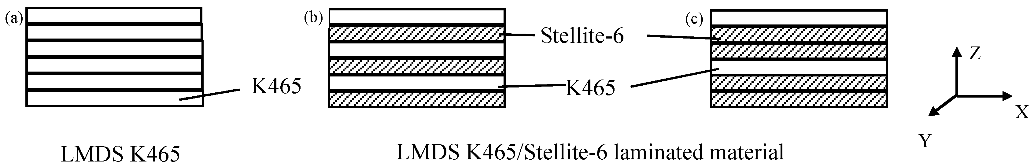
The three block samples deposition modes are illustrated in Figure 1. The K465 superalloy sample was built in a continuous way, as shown in Figure 1a. The K465/Stellite-6 laminated materials were built by LMDS alternately with deposition layer number ratios. One K465 deposited alternately with one and two Stellite-6 deposition layers, respectively, as shown in Figure 1b and Figure 2c. Laser power of 1450 W, scanning speed of 4 mm/s and scanning interval of 4 mm were used as manufacturing process parameters. The deposition direction of LMDS was paraller to the z-axis direction. The laminated material with deposition layer numbers ratio 1:1 and 1:2 was also, respectively, called 1:1 and 1:2 K465/Stellite-6 laminated material.
Specimens were cut from the building platform, and then mounted and polished. The K465 deposition sample was electrochemical etched with etchant (H3PO4 + HNO3 + H2SO4), using voltage of 6 V and etch time was 15 s. Two laminated materials were etched with chloroazotic acid. The microstructure of those specimens was observed by stereology microscopy (Stemi 2000, Carl Zeiss Shanghai Co., Ltd., Shanghai, China) and optical microscopy (Axiovert 200 MAT, Carl Zeiss Shanghai Co., Ltd., Shanghai, China). Elemental analysis was done by the energy dispersive spectrometry during SEM (S.3400N, Hitachi Ltd., Tokyo, Japan) analysis. The phase constitutions of the specimens were identified by an X-ray diffractometer (D/Max-2500PC, Rigaku Corp., Tokyo, Japan) and the hardness was measured by Vickers hardness tester (AMH43, LECO Corp., Saint Joseph, MI, USA) with an indentation load of 200 g for 15 s.
3. Results and Discussion
3.1. Microstructure
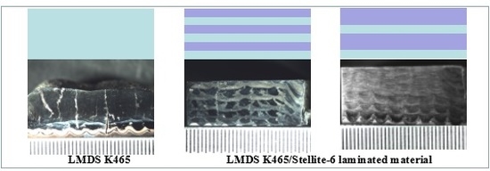
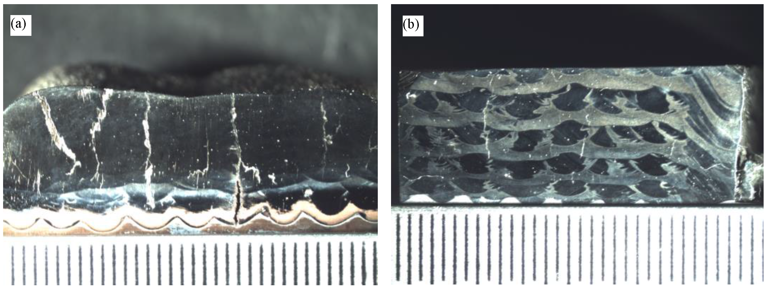
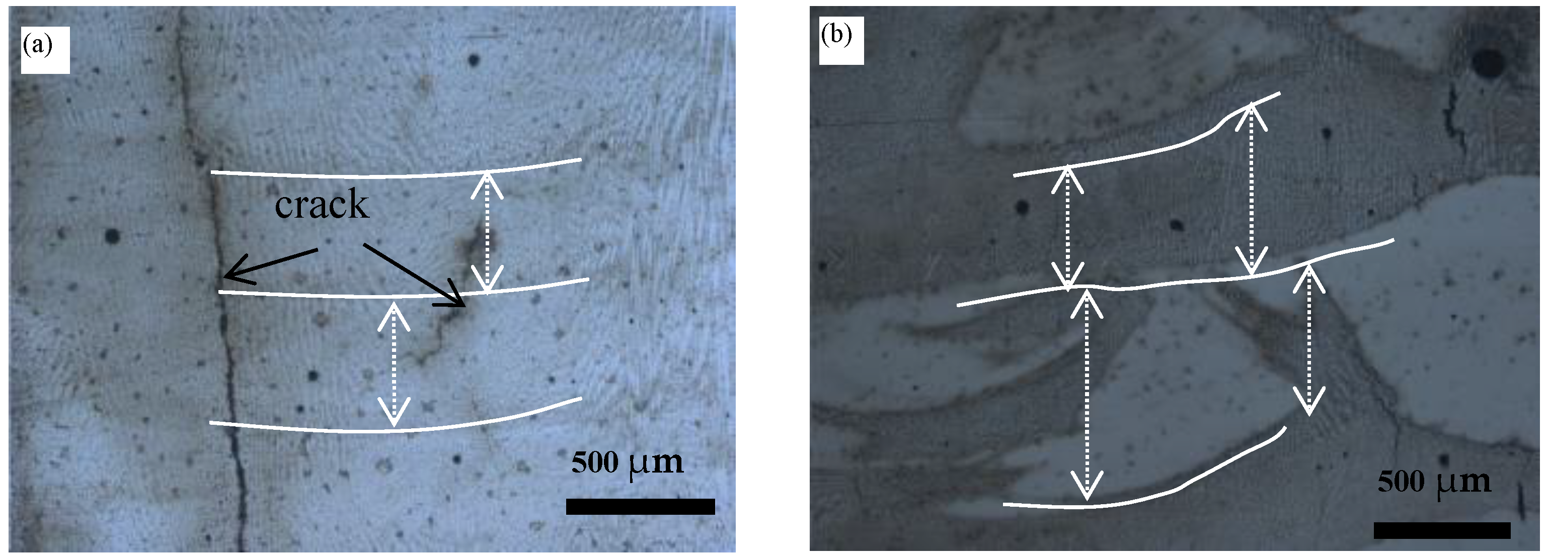
Figure 2 shows the macrostructure of the three samples in the X–Z section. As shown in Figure 2a), many cracks in LMDS K465 extended to the deposition layers along the deposition direction. The cracks in laminated material with deposition layer numbers ratio 1:1 terminated in single deposition layer (Figure 2b), and macrocracks disappeared in laminated material with deposition layer numbers ratio 1:2 (Figure 2c). A small number of round-hole defects distributed irregularly on the three samples. The deposition layer thickness of the bottom zone was smaller with the top zone, and this could be explained by different dimensions of the molten pool. It is clear that the temperature of the substrate and the previously built layer increased as deposition progressed, which made the dimensions of the molten pool become larger under the same condition of heat input.
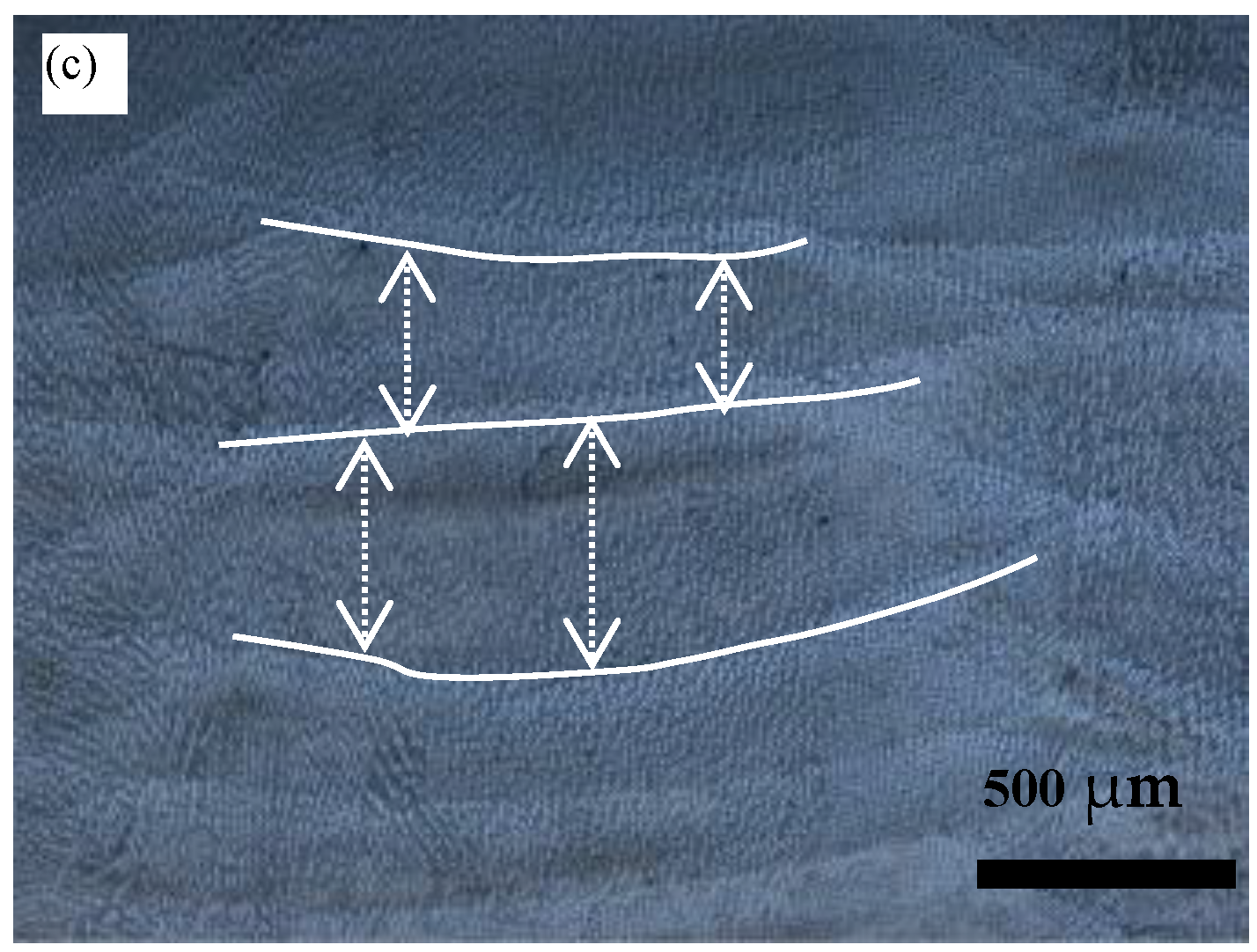
The deposition layer thickness of the laminated material was uneven in the single deposition layer, whereas the K465 deposition layers had nearly homogeneous thickness, as shown in Figure 3. This difference is closely related to the laser scanning strategy. As stated before, the zig-zag laser scanning strategy was used as shown in Figure 4. As illustrated in the left zone of Figure 4, the laser first moved along the solid line in red, and then moved along the dotted line in red to fill the gap left by previous scanning route. When LMDS was conducted on the previous layer, the top position of the previous deposition layer was remelted. Laser energy in distribution of Gaussian modes made the remelted line appear in a wavy shape. The remelted line shape of different materials varied, and this made the deposition layer thickness of laminated material non-uniform. The layer thickness of deposition layer in laminated material was changed along the x-direction, as shown in Figure 3b,c. At the same time, the single layer thickness of K465 superalloy was uniform with nearly 0.47 mm. As shown in Figure 3b,c, the liquation cracking first initiated from the heat affected zone, which was near the fusion line in the pre-deposition layer. The liquidation of low melting point phase in K465 superalloy leads to the occurrence of grain boundaries liquation cracking, which was proved by many researchers like Yan et al. [22] and Chen et al. [6,10,11]. The liquation crack in K465 superalloy extended along several deposition layers, while extended only in the K465 single layer of laminated material. The crack behavior was related to hot ductility of the material, capability to absorb the stress of welding, and the grain boundary misorientation. The laminated materials were freer of crack than K465 alone because of different material composition and welding dilution between different deposition layers. The crack difference between two laminated material was mainly because of different material composition. The 1:2 K465/Stellite-6 laminated material has more capability to absorb the stress of deposition.
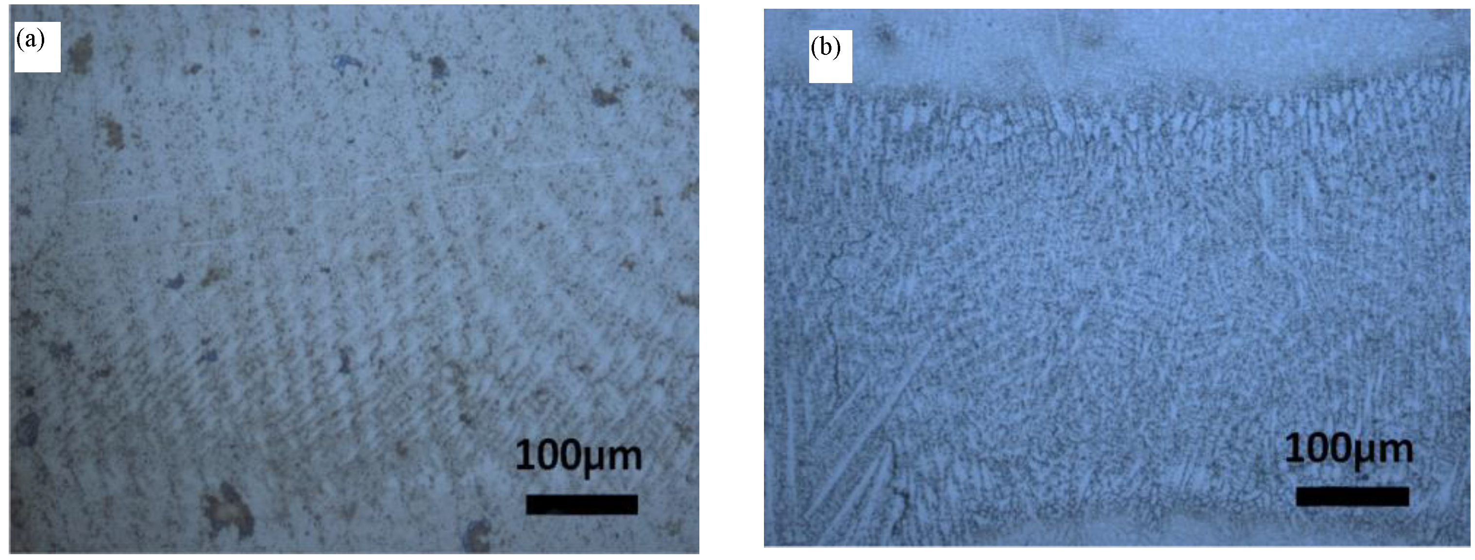
Figure 5 shows dendritic microstructures of different forming methods, and the microstructure of three samples mostly consist of dendrite structures. Mostly, the dendrites grew with orientation nearly parallel to the building direction, apart from the microstructure near the interlayer bonding. The dendrite arm spacing (DAS) was often used to evaluate solidification microstructures [23]. After calculating the average second dendrite arm spacing (SADS) of different forming methods by SEM images, the microstructures of laminated materials were refined compared with single K465 alloy. The SADS of LMDS K465 alloy was near 10.18 μm, while the laminated material with deposition layer numbers ratio 1:1 had 3.44 μm SADS. In addition, the primary dendritic developd more in the single alloy than the laminated materials. The deposition microstructure difference was partly caused by the variation of deposition mode. The K465 sample was formed by LMDS contentiously, while the laminated materials built by LMDS had a pause between different material deposition layer-to-layer. The deposition temperature gradient of laminated materials samples was greater than K465 samples with the same process parameters, which made the microstructure refined. Mohammad H. Farshidianfar has proven that the solidification structure and the geometrical dilution were closely related to the real-time cooling rate [24]. Comparing the dendritic microstructures of the three different forming methods, it is clear that the microstructure of the laminated material with deposition layer numbers ratio 1:1 was the smallest.
3.2. Phase Compositions
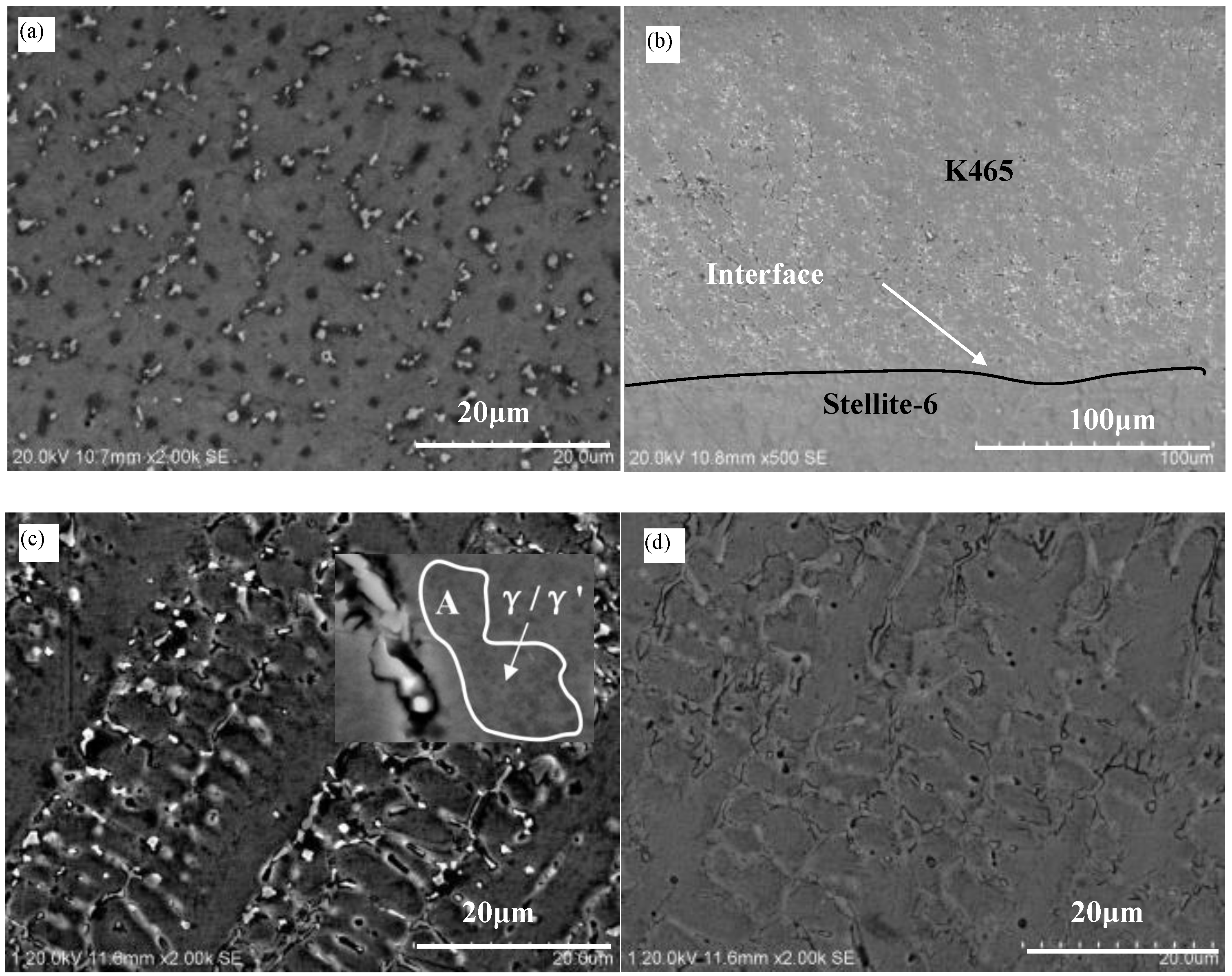
The phases of laser additive manufacturing K465 and Stellite-6 have been studied by many researchers. According to Li’s research, the microstructure of laser additive manufacturing consisted of γ’, MC and γ [25]. According to the research of microstructure of Stellite-6 [26,27,28], the Stellite-6 deposition microstructure might consist of γ (Co) and carbide formations (M23C6, M6C, M7C3). Figure 6a illustrates the microstructures of K465 by LMDS, and white precipitates appear discontinuously in the interdendritic, which was an MC phase. The microstructure and phase of laminated material with deposition layer numbers ratio 1:1 varied on account of different dissimilar alloys deposition layers. As shown in Figure 6b, carbide distributed on the upper part of the picture by block and continuous network morphology, while these disappear on the remaining part of the image. The interface of laminated material was fine, as shown in Figure 6b. No defects were found near the interface between different deposition layers, and the border of different material deposition layer was clear. The dendritic microstructures of different materials near the border were similar. The microstructures and phases of laminated material with deposition layer numbers ratio 1:2 and 1:1 had similar distribution, as illustrated in Figure 6c,d. Figure 6c,d were K465 and Stellite-6 deposition layers, respectively. The white carbide phases in piece and branch developed were in the interdendritic zone of K465 deposition layer, while the carbide phase in branch developed distributed in the interdendritic zone of Stellite-6 deposition layer.
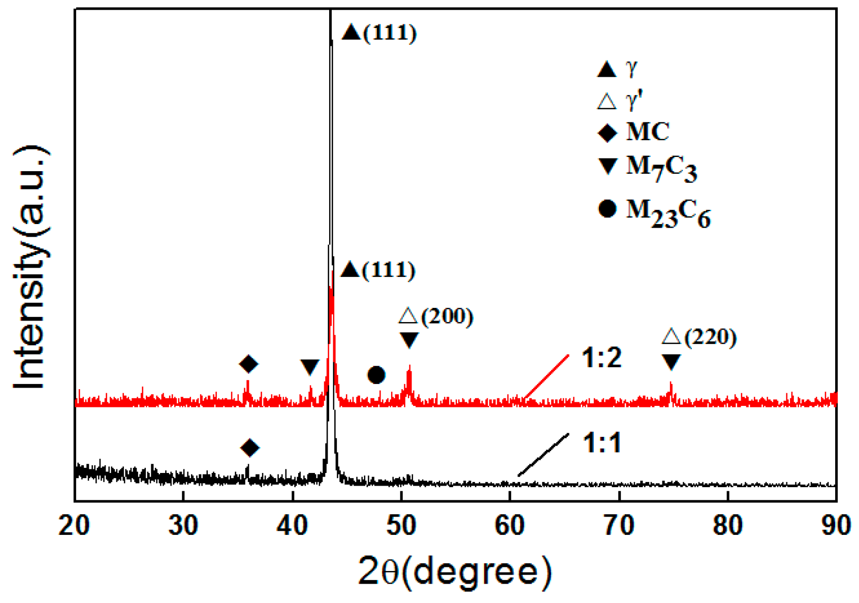
Figure 7 illustrates the X-ray diffraction (XRD) result of laminated materials’ X–Z section. According to the results, MC and γ were found in the laminated material with deposition layer numbers ratio 1:1, while laminated material with deposition layer numbers ratio 1:2 had γ, γ’, MC, M23C6, and M7C3. Figure 8 shows the EDS of different layers of laminated material with deposition layer numbers ratio 1:2, and the carbide phase distributions in the interdendritic of both K465 and Stellite-6 deposition layers had higher content of Cr and C elements than other areas. Apart from matrix phase elements, which were Ni and Co, other elements distribute without dendritic segregation. On account of the XRD results and the elements composition test, the carbide distributions in the interdendritic structure were M7C3. The M7C3 phase also existed in laminated material with deposition layer numbers ratio 1:1 based on the SEM image. According to the SEM image in a higher magnitude, as shown in A zone in Figure 6c, γ’/γ phase distributed near the interdendritic structure of the K465 deposition layer in both laminated materials. Therefore, the laminated material sample with deposition layer numbers ratio 1:2 consisted of γ’, γ, MC, M23C6, and M7C3.
The carbide content in K465 and laminated materials was different, which influenced the performance of the deposition alloy. The volume fraction of carbides was calculated by Image Plus Pro software (5.0, Media Cybernetics Inc., Rockville, MD, USA), and the volume fraction of carbides in LMDS single K465 superalloy was 3.17%. In the two kinds of laminated materials, the volume fraction of carbides in K465 superalloy deposition layers increased to 5.01%. The content of C element in Stellite-6 was higher than K465. The content of C element increased in the deposition layer of K465 in laminated materials because of the remelting of Stellite-6 deposition layer. According to Tang’s research, fluid flow in the moving molten pool occurred under the effect of recoil pressure and thermal-capillary force [29]. The top of the Stellite-6 previous deposition layer was melted, mixed, resulting in the content of C element in the K465 layer increasing. As a result, the deposition layer of K465 superalloy had a higher content of carbide.
3.3. Composition Distribution
The contents of Co, Ni and Cr elements, which were the fundamental formation of phases, cyclically fluctuate as shown in Figure 9. At the same time, the Al element, which was the formation of γ’ in K465 superalloy, also cyclically fluctuated. This phenomenon of composition changing along the deposition direction was consistent with the formation of laminated materials. Steep composition content changes occurred near the interface of laminated material. As shown in Figure 9a, the Ni content drastic variation from K465 to Stellite-6 deposition layer was a little weakened with Stellite-6 deposition layer to K465 deposition layer. This can be explained by the fluid flow phenomenon as mentioned before, where, during the deposition of Stellite-6 layer, the alloy of K465 was remelted and mixed. The Ni content in the bottom of the Stellite-6 deposition layer was weakly increased compared with Stellite-6 powders. The Co content variation in laminated materials with deposition layer numbers ratio 1:2 (Figure 9b) was nearly the same. The thickness of compositional variation zone was nearly 50–60 μm.
3.4. Microhardness Analysis
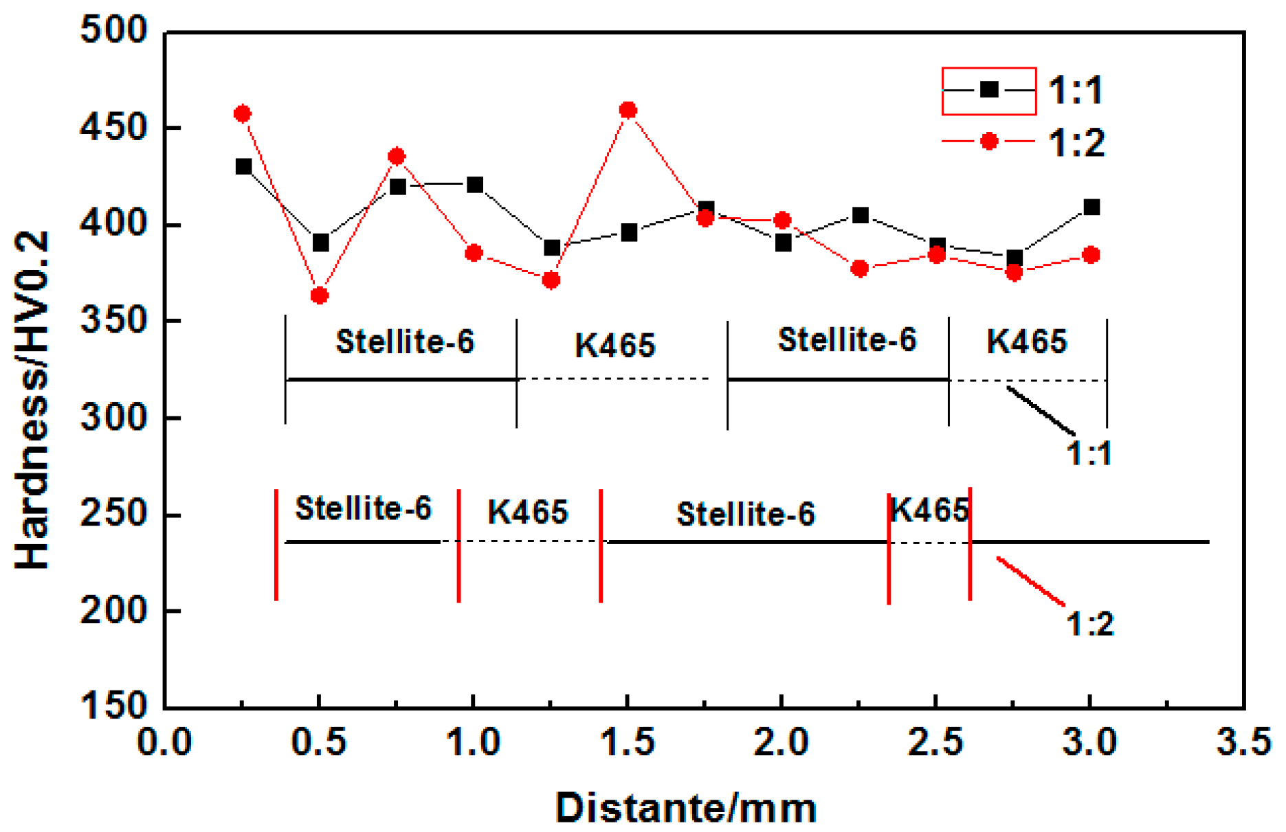
The microhardness variation occurred along the building direction of laminated materials as the composition variation, as demonstrated in Figure 10. According to the analysis of Vickers hardness (HV) test and microstructure, the Stellite-6 deposition layer had the higher value of Vickers hardness compared to the K465 deposition layer. The microhardness difference was mainly affected by the grain size of structure and phase compositions. The Stellite-6 layer in laminated materials had higher contents of carbide than the K465 layer, and both of the microstructure grain sizes were similar. The microhardness difference between the different deposition layer decreased as the deposition layer height increased away from the substrate. The microhardness variation had a dissimilarity between the previous building layer and others because the dilution rate of the previous deposition layer was lower during the former deposition process. As the deposition layer grew, the substrate temperature of the next deposition layer was increased and stabilized. This made the dilution rate of the former deposition layer increase, leading to the different composition phases being reduced. The microhardness of laminated materials with different deposition layer numbers ratio had similar evolution rules, where the microhardness of layer numbers ratio 1:1 and 1:2 were, respectively, around 400 and 380 HV0.2. The weak difference was caused by deposition direction and grain size.
4. Conclusions
(1) The crack tendency in LMDS K465/Stellite-6 laminated materials was significantly reduced compared with LMDS single K465 superalloy.
(2) The microstructure in laminated materials was refined compared with LMDS single K465 superalloy. Compared with LMDS K465, the K465 deposition layer in laminated material samples had a higher content of carbide. The K465/Stellite-6 1:2 laminated material sample consisted of γ, γ’, MC, M23C6, M7C3 phases.
(3) The composition and microhardness distribution of laminated materials showed a variation occurring along the building direction. A weak composition gradual variation happened on the interface of different layers because of the remelting of the previous build layer. The microhardness of layer numbers ratio 1:1 and 1:2 were, respectively, around 400 and 380 HV0.2.
Acknowledgments
The authors would like to acknowledge the National Science-technology Support Plan Projects (Grant No. 2015BAF08B01-01) and the National Key Research and Development Programme of China (Grant No. 2016YFB1100502)
Author Contributions
Jibin Zhao and Zhiguo Wang conceived and designed the experiments; Fan Shi and Hongyu Zhang performed the experiments; Zhiguo Wang and Yuhui Zhao analyzed the data; Zhiguo Wang wrote the paper.
Conflicts of Interest
The authors declare no conflict of interest.
References
- Yang, J.X.; Zheng, Q.; Sun, X.F.; Guan, H.R.; Hu, Z.Q. Relative stability of carbides and their effects on the properties of K465 superalloy. Mater. Sci. Eng. A 2006, 429, 341–347. [Google Scholar] [CrossRef]
- Bi, G.J.; Sun, C.N.; Chen, H.C.; Ng, F.L.; Ma, C.C.K. Microstructure and tensile properties of superalloy IN100 fabricated by micro-laser aided additive manufacturing. Mater. Des. 2014, 60, 401–408. [Google Scholar] [CrossRef]
- Zhang, K.; Liu, W.J.; Shang, X.F. Research on the processing experiments of laser metal deposition shaping. Opt. Laser Technol. 2007, 39, 549–557. [Google Scholar] [CrossRef]
- Dinda, G.P.; Dasgupta, A.K.; Mazumder, J. Texture control during laser deposition of nickel-based superalloy. Scr. Mater. 2012, 67, 503–506. [Google Scholar] [CrossRef]
- Zhong, C.; Pirch, N.; Gasser, A.; Gasser, A.; Poprawe, R.; Schleifenbaum, J.H. The Influence of the Powder Stream on High-Deposition-Rate Laser Metal Deposition with Inconel 718. Metals 2017, 7, 443. [Google Scholar] [CrossRef]
- Chen, Y.; Zhang, K.; Huang, J.; Hosseini, S.R.E.; Li, Z.G. Characterization of heat affected zone liquation cracking in laser additive manufacturing of Inconel 718. Mater. Des. 2016, 90, 586–594. [Google Scholar] [CrossRef]
- Angelastro, A.; Campanelli, S.L.; Casalino, G. Statistical analysis and optimization of direct metal laser deposition of 227-F Colmonoy nickel alloy. Opt. Laser Technol. 2017, 94, 138–145. [Google Scholar] [CrossRef]
- Acharya, R.; Bansal, R.; Gambone, J.J.; Kaplan, M.A.; Fuchs, G.E.; Rudawski, N.G.; Das, S. Additive Manufacturing and Characterization of René 80 Superalloy Processed Through Scanning Laser Epitaxy for Turbine Engine Hot-Section Component Repair. Adv. Eng. Mater. 2015, 17, 942–950. [Google Scholar] [CrossRef]
- Acharya, R.; Das, S. Additive manufacturing of IN100 superalloy through scanning laser epitaxy for turbine engine hot-section component repair: process development, modeling, microstructural characterization, and process control. Metall. Mater. Trans. A 2015, 46, 3864–3875. [Google Scholar] [CrossRef]
- Yang, J.J.; Li, F.Z.; Wang, Z.M.; Zeng, X.Y. Cracking behavior and control of Rene 104 superalloy produced by direct laser fabrication. J. Mate. Process. Technol. 2015, 225, 229–239. [Google Scholar] [CrossRef]
- Li, Q.G.; Lin, X.; Wang, X.H.; Yang, H.O.; Song, M.; Huang, W.D. Research on the Grain Boundary Liquation Mechanism in Heat Affected Zones of Laser Forming Repaired K465 Nickel-Based Superalloy. Metals 2016, 6, 64. [Google Scholar] [CrossRef]
- Hu, Y.L.; Lin, X.; Song, K.; Jiang, X.Y.; Yang, H.O.; Huang, W.D. Effect of heat input on cracking in laser solid formed DZ4125 superalloy. Opt. Laser Technol. 2016, 86, 1–7. [Google Scholar] [CrossRef]
- Carter, L.N.; Martin, C.; Withers, P.J.; Attallah, M.M. The influence of the laser scan strategy on grain structure and cracking behaviour in SLM powder-bed fabricated nickel superalloy. J. Alloys Compd. 2014, 615, 338–347. [Google Scholar] [CrossRef]
- Hu, Y.L.; Lin, X.; Yu, X.B.; Xu, J.J.; Lei, M.; Huang, W.D. Effect of Ti addition on cracking and microhardness of Inconel 625 during the laser solid forming processing. J. Alloys Compd. 2017, 711, 267–277. [Google Scholar] [CrossRef]
- Harrison, N.J.; Todd, I.; Mumtaz, K. Reduction of micro-cracking in nickel superalloys processed by selective laser melting: A fundamental alloy design approach. Acta Mater. 2015, 94, 59–68. [Google Scholar] [CrossRef]
- Angelastro, A.; Campanelli, S.L.; Casalino, G.; Ludovico, A.D. Optimization of Ni-based WC/Co/Cr composite coatings produced by multilayer laser cladding. Adv. Mater. Sci. Eng. 2013, 2013, 1–7. [Google Scholar] [CrossRef]
- Abe, T.; Sasahara, H. Dissimilar metal deposition with a stainless steel and nickel-based alloy using wire and arc-based additive manufacturing. Precis. Eng. 2016, 45, 387–395. [Google Scholar] [CrossRef]
- Shah, K.; Haq, I.U.; Khan, A.; Shah, S.A.; Khan, M.; Pinkerton, A.J. Parametric study of development of Inconel-steel functionally graded materials by laser direct metal deposition. Mater. Des. 2014, 54, 531–538. [Google Scholar] [CrossRef]
- Liu, B.X.; Huang, L.J.; Rong, X.D.; Geng, L.; Yin, F.X. Bending behaviors and fracture characteristics of laminated ductile-tough composites under different modes. Compos. Sci. Technol. 2016, 126, 94–105. [Google Scholar] [CrossRef]
- Soodi, M.; Masood, S.H.; Brandt, M. Thermal expansion of functionally graded and wafer-layered structures produced by laser direct metal deposition. Int. J. Adv. Manuf. Technol. 2013, 69, 2011–2018. [Google Scholar] [CrossRef]
- Kolednik, O.; Predan, J.; Fisher, F.D.; Fratzl, P. Improvements of strength and fracture resistance by spatial material property variations. Acta Mater. 2014, 68, 279–294. [Google Scholar] [CrossRef]
- Yan, F.; Liu, S.; Hu, C.; Wang, C.M.; Hu, X.Y. Liquation cracking behavior and control in the heat affected zone of GH909 alloy during Nd: YAG laser welding. J. Mater. Process. Technol. 2017, 244, 44–50. [Google Scholar] [CrossRef]
- Yin, H.; Felicelli, S.D. Dendrite growth simulation during solidification in the LENS process. Acta Mater. 2010, 58, 1455–1465. [Google Scholar] [CrossRef]
- Farshidianfar, M.H.; Khajepour, A.; Gerlich, A.P. Effect of real-time cooling rate on microstructure in laser additive manufacturing. J. Mater. Process. Technol. 2016, 231, 468–478. [Google Scholar] [CrossRef]
- Li, Q.G.; Lin, X.; Liu, F.G.; Liu, F.C.; Huang, W.D. Microstructural characteristics and mechanical properties of laser solid formed K465 superalloy. Mater. Sci. Eng. A 2017, 700, 649–655. [Google Scholar] [CrossRef]
- Bartkowski, D.; Mlynarczak, A.; Piasecki, A.; Dudziak, B.; Goscianski, M.; Bartkowska, A. Microstructure, microhardness and corrosion resistance of Stellite-6 coatings reinforced with WC particles using laser cladding. Opt. Laser Technol. 2015, 68, 191–201. [Google Scholar] [CrossRef]
- Apay, S.; Gulenc, B. Wear properties of AISI 1015 steel coated with Stellite 6 by microlaser welding. Mater. Des. 2014, 55, 1–8. [Google Scholar] [CrossRef]
- Shoja-Razavi, R. Laser Surface Treatment of Stellite 6 Coating Deposited by HVOF on 316L Alloy. J. Mater. Eng. Perform. 2016, 25, 2583–2595. [Google Scholar] [CrossRef]
- Tang, Q.; Pang, S.Y.; Chen, B.B.; Suo, H.B.; Zhou, J.X. A three dimensional transient model for heat transfer and fluid flow of weld pool during electron beam freeform fabrication of Ti-6-Al-4-V alloy. Int. J. Heat Mass Trans. 2014, 78, 203–215. [Google Scholar] [CrossRef]
Figure 1.
The schematic of the different forming method (a) K465; (b) 1:1 K465/Stellite-6 laminated material; (c) 1:2 K465/Stellite-6 laminated material.
Figure 1.
The schematic of the different forming method (a) K465; (b) 1:1 K465/Stellite-6 laminated material; (c) 1:2 K465/Stellite-6 laminated material.

Figure 2.
Macrostructure of Laser metal deposition shaping (LMDS) samples (a) K465; (b) 1:1 K465/Stellite-6 laminated material; (c) 1:2 K465/Stellite-6 laminated material.
Figure 2.
Macrostructure of Laser metal deposition shaping (LMDS) samples (a) K465; (b) 1:1 K465/Stellite-6 laminated material; (c) 1:2 K465/Stellite-6 laminated material.


Figure 3.
Optical microscopy (OM) images of LMDS samples: (a) K465; (b) 1:1 K465/Stellite-6 laminated material; (c) 1:2 K465/Stellite-6 laminated material.
Figure 3.
Optical microscopy (OM) images of LMDS samples: (a) K465; (b) 1:1 K465/Stellite-6 laminated material; (c) 1:2 K465/Stellite-6 laminated material.


Figure 4.
The schematic of LMDS of laminated materials.
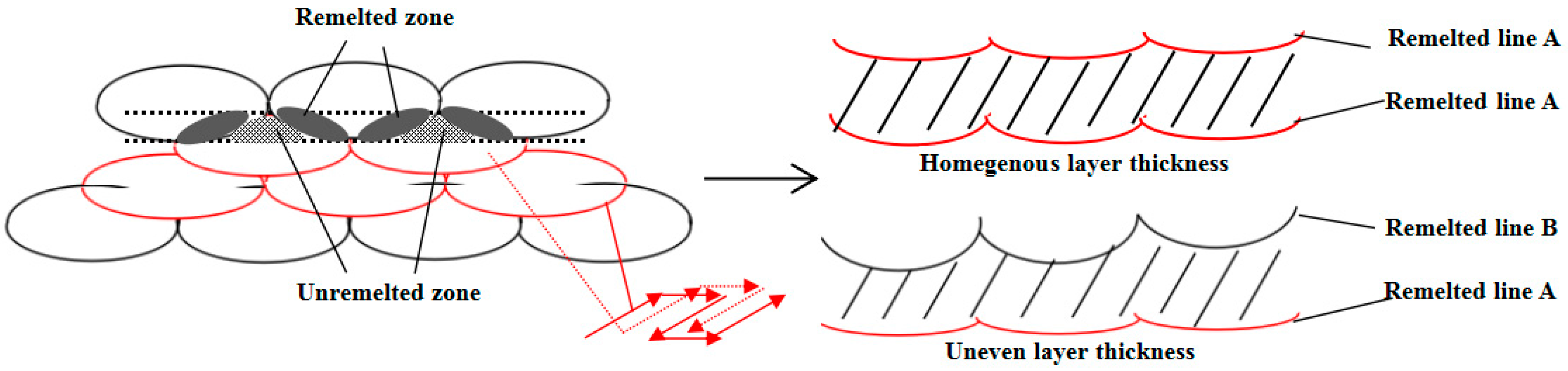
Figure 5.
The dendritic microstructures of different forming methods: (a) K465; (b) 1:1 K465/Stellite-6 laminated material; (c) 1:2 K465/Stellite-6 laminated material.
Figure 5.
The dendritic microstructures of different forming methods: (a) K465; (b) 1:1 K465/Stellite-6 laminated material; (c) 1:2 K465/Stellite-6 laminated material.

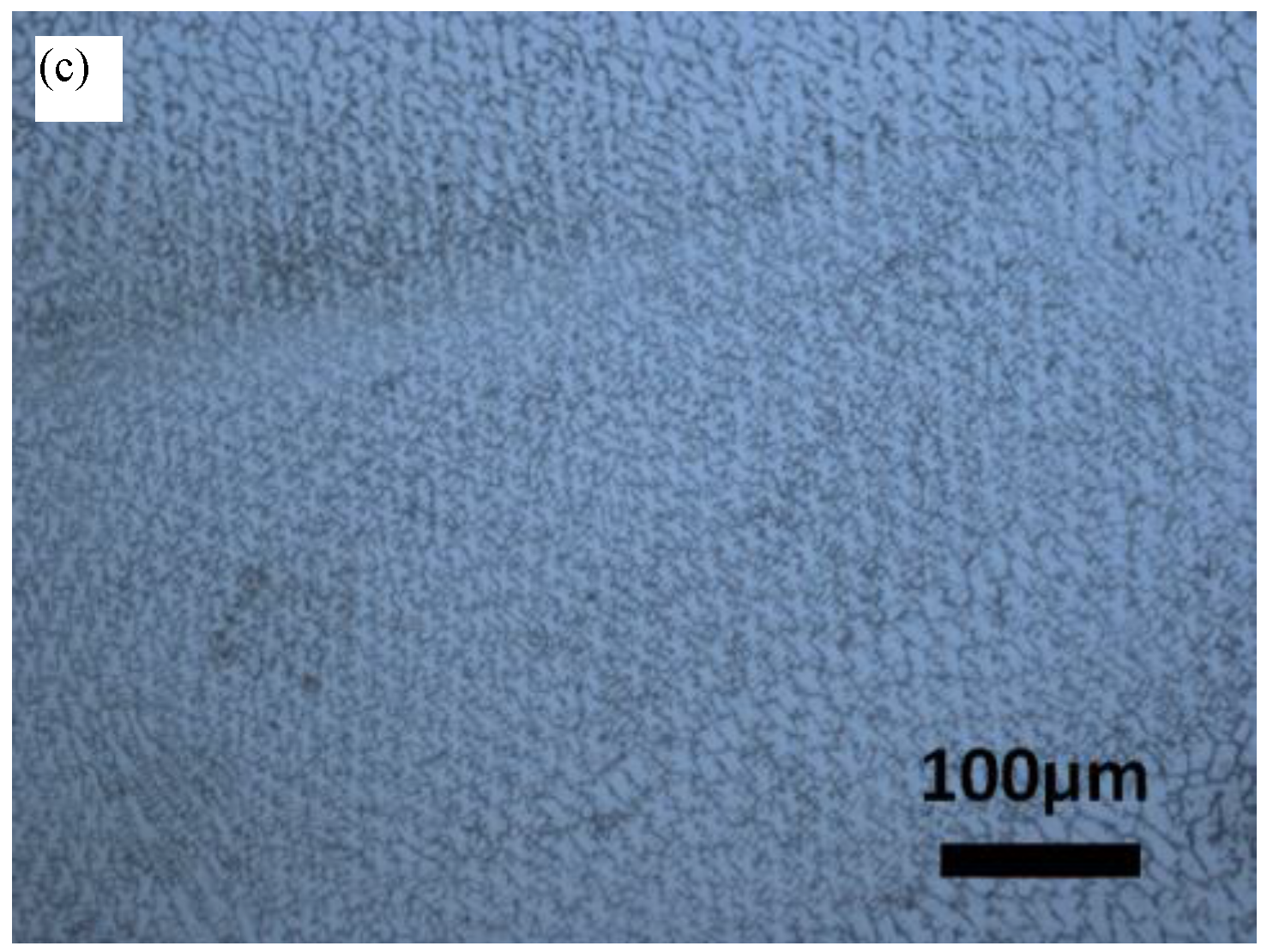
Figure 6.
Scanning electron microscope (SEM) images of LMDS K465 superalloy: (a) K465; (b) 1:1 K465/Stellite-6 laminated material; (c) K465 deposition layer in 1:2 K465/Stellite-6 laminated material; (d) Stellite-6 deposition layer in 1:2 K465/Stellite-6 laminated material.
Figure 6.
Scanning electron microscope (SEM) images of LMDS K465 superalloy: (a) K465; (b) 1:1 K465/Stellite-6 laminated material; (c) K465 deposition layer in 1:2 K465/Stellite-6 laminated material; (d) Stellite-6 deposition layer in 1:2 K465/Stellite-6 laminated material.

Figure 7.
X-ray diffraction (XRD) spectra of different laminated materials.

Figure 8.
Energy dispersive X-ray spectroscopy (EDS) of different layers of laminated material 1:2. (a) K465 deposition laye; (b) Stellite-6 deposition layer.
Figure 8.
Energy dispersive X-ray spectroscopy (EDS) of different layers of laminated material 1:2. (a) K465 deposition laye; (b) Stellite-6 deposition layer.
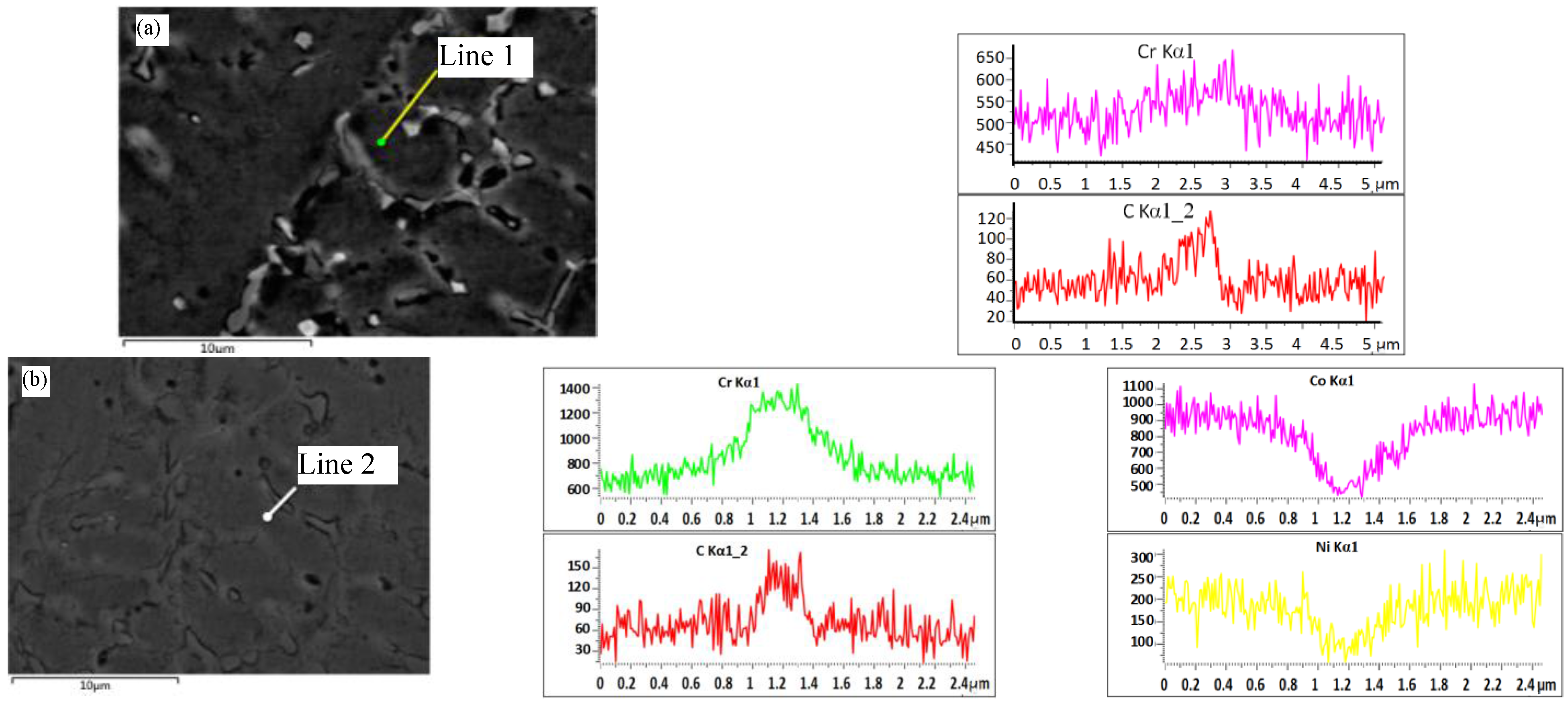
Figure 9.
EDS line scan profiles along the build directions of different laminated materials: (a) 1:1; (b) 1:2.
Figure 9.
EDS line scan profiles along the build directions of different laminated materials: (a) 1:1; (b) 1:2.
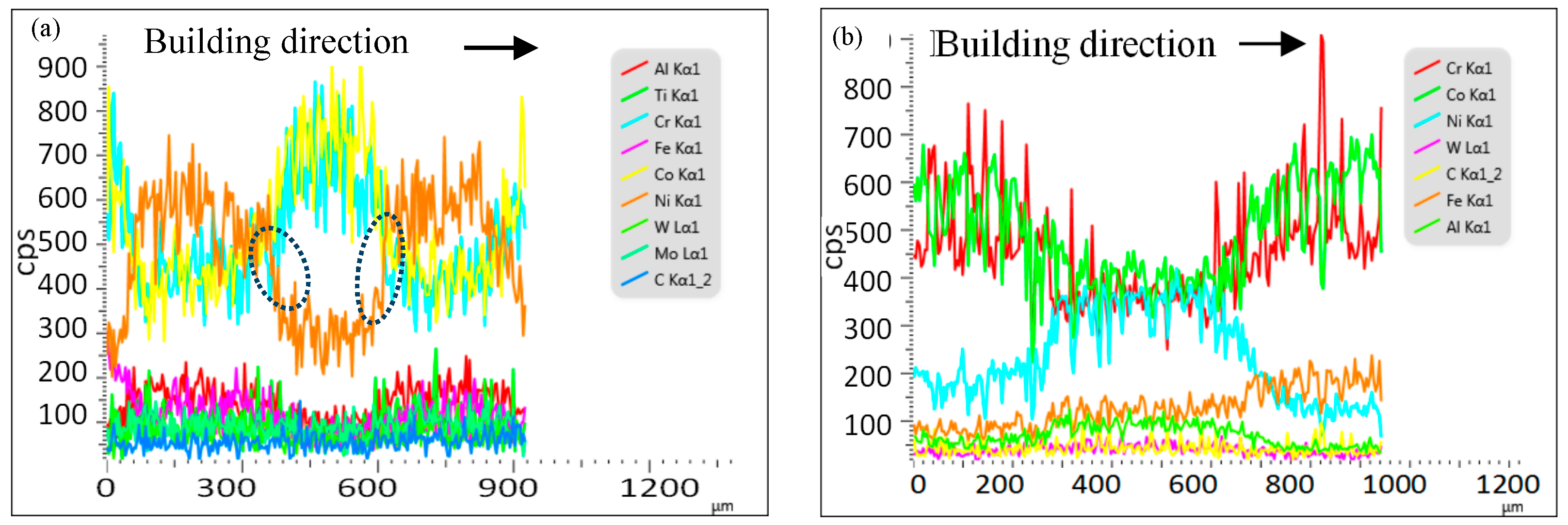
Figure 10.
Hardness curve of K465/Stellite-6 laminated materials.


Table 1.
Chemical composition of powders.
| Element | C | Mo | Cr | Nb | Fe | Ti | Si | Al | W | Mn | Co | Ni |
|---|---|---|---|---|---|---|---|---|---|---|---|---|
| K465 | 0.17 | 1.80 | 8.75 | 2.00 | - | 2.45 | - | 5.55 | 10.25 | - | 9.75 | Bal. |
| Stellite-6 | 1.09 | 0.22 | 29.27 | - | 1.93 | - | 1.00 | - | 4.29 | 0.13 | Bal. | 2.34 |
© 2017 by the authors. Licensee MDPI, Basel, Switzerland. This article is an open access article distributed under the terms and conditions of the Creative Commons Attribution (CC BY) license (http://creativecommons.org/licenses/by/4.0/).
Share and Cite
MDPI and ACS Style
Wang, Z.; Zhao, J.; Zhao, Y.; Zhang, H.; Shi, F. Microstructure and Microhardness of Laser Metal Deposition Shaping K465/Stellite-6 Laminated Material. Metals 2017, 7, 512. https://doi.org/10.3390/met7110512
AMA Style
Wang Z, Zhao J, Zhao Y, Zhang H, Shi F. Microstructure and Microhardness of Laser Metal Deposition Shaping K465/Stellite-6 Laminated Material. Metals. 2017; 7(11):512. https://doi.org/10.3390/met7110512
Chicago/Turabian StyleWang, Zhiguo, Jibin Zhao, Yuhui Zhao, Hongyu Zhang, and Fan Shi. 2017. "Microstructure and Microhardness of Laser Metal Deposition Shaping K465/Stellite-6 Laminated Material" Metals 7, no. 11: 512. https://doi.org/10.3390/met7110512
Note that from the first issue of 2016, this journal uses article numbers instead of page numbers. See further details here.