Wear of Shaped Surfaces of PVD Coated Dies for Clinching


1
Institute of Materials Research, Slovak Academy of Sciences, Watsonova 1935/47, 040 01 Košice, Slovakia
2
Department of Computer Support of Technology, Faculty of Mechanical Engineering, Technical University of Košice, Mäsiarska 74, 040 01 Košice, Slovakia
3
Department of Mechanical Technology and Materials, Faculty of Mechanical Engineering, Technical University of Košice, Mäsiarska 74, 040 01 Košice, Slovakia
*
Author to whom correspondence should be addressed.
Metals 2017, 7(11), 515; https://doi.org/10.3390/met7110515
Submission received: 10 October 2017
/
Revised: 8 November 2017
/
Accepted: 8 November 2017
/
Published: 21 November 2017
Abstract
:A clinching method that uses a simple toolset consisting of a punch and a die, is utilized for joining lightweight materials. This paper is aimed at investigating the wear of the die cavity of a clinching tool. A clinching tool with a specially shaped cavity was used for joining thin hot-dip galvanized steel sheets. Various types of physical vapour deposition (PVD) coatings such as ZrN, CrN and TiCN were deposited on the shaped surface of the die using Lateral Rotating Arc-Cathodes technology. Hot-dip galvanized steel sheets were used for testing the clinching tool. The material properties of PVD coatings that were deposited on the shaped part of the clinching die were evaluated. Finite Element Analysis was used to localize the area of the shaped part of the die and the part of surface area of the cylindrical die cavity of ϕ 5.0 mm, in which high contact pressure values were predicted. The prediction of the start of the wear cycle was verified experimentally by the clinching of 300 samples of hot-dip galvanized steel sheets. Unlike the CrN and ZrN coatings, the TiCN coating remained intact on the entire surface of the die.

1. Introduction
Mechanical joining technologies, such as clinching, clinch-riveting and self-piercing riveting have been proved effective for joining lightweight materials with high strength. Lightweight constructions have gained considerable interest in recent years, because of their economic and environmental properties. Among the mechanical joining methods, the clinching technology has been developed rapidly. Unlike clinching, clinch-riveting and self-piercing riveting require a rivet, which may increase the weight of the joint. However, a higher forming load is necessary [1,2]. Clinching has been used on an industrial scale for over 30 years and has been successfully applied to a wide variety of materials and material combinations. Clinching is commonly utilized in car body production [3], building components [4], even in electrical industries. It is a cold joining process of sheets by local hemming with a punch and die. The material between the punch and die is forced into a radial flow to form the undercut. This method belongs among forming joining technologies. The joined sheets are deformed locally by creating a mechanical interlock. It is used for joining thin sheets from 0.5 to 4 mm single sheet in thickness, up to a total joint thickness of about 20 mm. The load-bearing capacity of the clinched joint mainly depends on the geometrical parameters of the joint profile, which is mainly influenced by process parameters and the clinching die [5,6,7,8].
It is a great advantage that clinching does not generate any thermal stress that would affect the joined materials. The clinching is a low energy process and does not destroy coating or produce fumes such as occur with resistance spot welding. What is more, it does not require a pre-drilled hole and it is not necessary to specially prepare the surfaces of the joined materials. This highly flexible method can therefore be employed for joining a wide range of materials. Previous research focused on joining steels and aluminum alloys; however, recent experiments have also dealt with copper, magnesium, titanium alloys [9,10], carbon fiber-reinforced plastics [11], hybrid metal-plastic polymers [12,13] as well as metal-reinforced plastics [14,15]. When joining the abovementioned materials by this method, there may occur a problem with limited metal formability. This can be avoided by pre-heating the materials or by changing the material flow to prevent the formation of cracks [16].
A number of experimental studies have been carried out to understand the forming process of clinched joints. These experiments usually take a long time to perform and they are quite expensive, especially when tool geometry or material properties should be modified. For this reason, the Finite Element Method (FEM) is frequently utilized [17,18,19]. The information that can be obtained from the simulation of the clinching process includes the following: material flow, distribution of strains and stresses, distribution of pressure at the interference of the die and material, the influence of friction, and filling of the die gap with the joined materials [19].
Primarily, recent numerical studies of clinching have focused on fastening procedures of the joints [4,20]. Regarding the modeling strategies, a significant majority of the investigations performed 2D axial-symmetric simulations using dynamic explicit or static implicit Finite Element (FE) techniques for the numerical treatment [21,22,23]. The dimensional reduction of the analysis from 3D to 2D can be accomplished under certain circumstances, particularly with regard to the mechanical behavior of the sheet-isotropic material behavior [24]. A finite element procedure with an automatic remeshing technique was developed by Hamel et al. and Oudjene et al. [25,26] to simulate the clinching process. The resolution of an updated Lagrangian formulation is based on a static explicit approach. Comparative studies of clinching tools for joining the high-strength sheet metals of various thicknesses were conducted by Varis [23,27]. Numerical investigations were utilized in the study into the strength and energy absorption of the clinched joints [28,29,30]. A study into the evaluation of the material flow in the extendable die using FE simulation was conducted by Lambiase et al. [13,31,32]. Yang et al. [33] developed an ANSYS FE model for simulating the clinching process on the base of the elastic-plastic FE theory. The influences of the die parameters and combinations of sheets thickness on the interlock and neck thickness were investigated. Finite element simulations were also carried out by Mori et al. [34] for clinching high-strength steel and aluminum alloy sheets. The experimental research proved that the FE-based advanced calculation techniques can also serve as tools for predicting coating behavior [35,36].
High-strength steel sheets have a different hardening system than low-carbon steel sheets during the forming process. The usage of high-strength steels imposes higher requirements on the tool’s surfaces, as it significantly increases tool wear. The intensity of surface wear on the active parts of the forming tool can be influenced by the choice of tool material, its heat treatment or chemical surface treatment. There are numerous surface treatments, including currently commonly used physical vapour deposition (PVD) coatings [37,38,39,40]. In the process of clinching hot-dip galvanized steel sheets, the surface of the hard PVD coating deposited on the tool (die) comes in contact with a relatively soft zinc layer. There is an interaction between the surface of the hard tool, i.e., the die, and the surface of the zinc layer on the steel sheet [41]. Generally, it is a complex interaction that depends on the manufacturing process conditions and includes the interaction among the material of the sheet, the tool and the lubricant. The initial phase of wear is called galling. It is a form of adhesive wear that causes the transfer of material from the sheet to the forming tool during the forming process [42,43]. It results in zinc powdering accompanied with the surface damage or material loss of both bodies of the contact pair [39,44]. Experimental research into the phenomenon of galling focused on the influence of the surface topography of the processed sheets [45], type of PVD coating and roughness of coating deposited on the tool [46], the microstructure of tool material in relation to galling [47]. Attempts to develop prediction models for friction and galling were based on the simple contact between the surfaces; nevertheless, the sheet metal forming process is considerably more complicated [48,49]. The friction mechanisms depend on various factors, such as physical, chemical and material properties [39].
Adhesion, hardness, thickness and roughness are the properties of PVD coatings that notably affect the failure mechanism of these coatings [50,51,52,53,54]. Adhesion between the coating and the substrate, which is defined as the work necessary to separate the two [50], is among the basic criteria when evaluating the suitability of the system for a particular use. The most commonly used method for measuring the adhesion, i.e., the bonding strength between the coating and the substrate is the scratch test. After the scratch test, the adhesive properties of PVD coatings are evaluated by examining the morphology of coating failure, using the record of acoustic emission signal, friction coefficient μ and the critical force under which PVD coating is perforated until the substrate appears [55]. The scratch test and X-ray diffraction proved that the level of residual stress in the coating increases with increased roughness of the material surface on which the PVD coating was deposited [56]. The aim of the experiments was to identify the die wear mechanisms when clinching thin hot-dip galvanized steel sheets. The punch wear during the clinching process has already been investigated in [57,58], which is a mating component to the die in a complex tool for joining by clinching.
In the research a FEM was used to simulate the clinching process to predict the critical areas, in which the occurrence of wear can be expected. The FEM analysis is based on the ideal state of homogeneous isotropic continuum. The purpose of FEM analysis was to locate the areas that are critical in terms of coating failure. The actual experiment uses a system approach to the identification of the main parameters in the joining process of hot-dip galvanized sheets, which affect the degradation of the tool surface The FEM analysis of stresses in the die during the clinching process provides information about the surface of the shaped area that has the potential to wear as the first. An experimental verification of the prediction of the start of the wear cycle was performed by clinching of hot-dip galvanized steel sheets. Laboratory testing techniques for PVD coatings give only partial information about the wear of the die surface during the clinching process. Friction mechanisms depend on various factors, such as physical, chemical and material properties. A tool made of 1.3343 steel tempered to 55 HRc with PVD coatings of CrN, ZrN and TiCN MP (MP-Multi-Purpose multilayer) was tested at clinching of hot-dip galvanized thin steel sheets H220PD.
A qualitative concept of the stress distribution on the surface and just beneath the surface of the die during the clinching process of hot-galvanized steel sheets could be obtained by Finite Element Analysis (FEA) of stresses. This is a qualitative computation. In actual clinching, the system of the coating on the steel tool substrate interacts with the system of galvanized zinc coating on the steel sheet. The stress-strain interaction of these two systems is a function of physical and geometric parameters that characterize both systems. These parameters affect each other and can vary in intensity during the clinching process.
2. Materials and Methods
2.1. Clinching Process
Clinching is a mechanical joining method that involves local plastic deformation of two or more sheets. The sheets being joined are overlapped and plastically deformed by moving the punch against the sheets to produce an interlock that fastens the sheets. The formation of the interlock is controlled by the die, the shape of which determines the material flow during the joining process [7,31,59].
This method can be used to join materials of various thicknesses. The clinching process requires a force that depends on the material properties and the size of the tool (punch a die). Since there is no heat generated during the process, clinching is considered to be a cheap and flexible method [60].
The clinching process can be described by following steps [17]:
- The punch and blank holder move downward; the work pieces are clamped and fixed by the force of the blank holder.
- The material flows into the bottom die cavity forming a cup. The process parameters and dimensions of the punch and die are finely tuned to the sheet thickness of the workpieces. This insures that no material is laterally drawn into the joint from the surrounding area.
- The thickness of the cup’s bottom is reduced by upsetting, and the material forced into the die groove and in lateral direction, forming the necessary interlock.
- After reaching a predetermined maximum force or a predetermined displacement, the punch is retracted and the clamping force relieved.
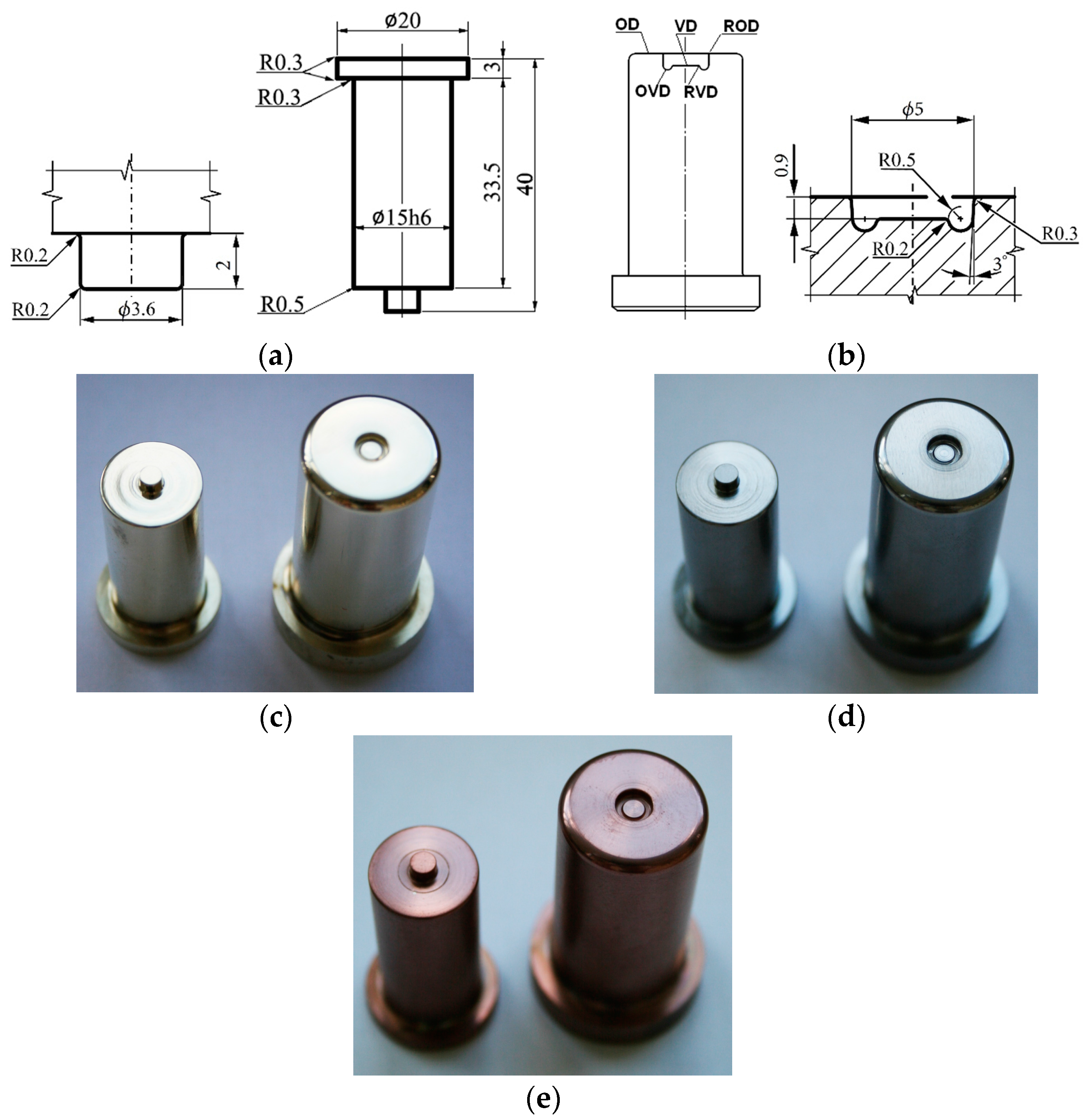
The clinching tool consists of two active parts involved in the joining process, a punch (Figure 1a) and a die (Figure 1b). A clinching tool with a punch of ϕ 3.6 mm and a die of ϕ 5 mm with a specially formed circular cavity and an annular gap was used in the experiments for joining thin hot-dip galvanized steel sheets. Three sets of tools with different PVD coatings on the punch and the die were made: ZrN (Figure 1c), CrN (Figure 1d) TiCN MP (Figure 1e), using LARC (Lateral Rotating Arc–Cathodes) technology. The coating deposition parameters were as follows:
- ZrN: Bias 160 V, ARC 180 A, pressure 0.008 mbar, temperature 430 °C;
- CrN: Bias 80 V, ARC Cr 140 A, pressure 0.04 mbar, temperature 450 °C;
- TiCN MP: Bias 100 V, ARC Ti 4 × 150 A, pressure 0.0037 mbar, temperature 450 °C.
In all three cases, the coating was deposited in several steps. The listed parameters are the main deposition steps; in case of the TiCN MP gradient they are the longest steps. The clinching tool punches and dies were tested experimentally by joining thin hot-dip galvanized steel sheets with the pressing force of 7000 N.
Tools made of 1.3343 steel were hardened and tempered (three times) to a hardness of 55–56 HRc. The tempering temperature was higher than the deposition temperature of PVD coatings. The tool surface was machined to a roughness lower than Ra = 0.2 µm. With each set of tools, test specimens made of 1.3343 steel ϕ 50 mm × 3 mm and ϕ 26–30 mm × 3 mm were heat-treated, machined and coated in the same way. The chemical composition of the steel was determined by the optical emission spectroscopy (OES, Thermo ARL, Lausanne, Switzerland) method and the PVD coatings were analyzed by Glow Discharge Optical Emission Spectroscopy (GD-OES, Leco Instrument, Joseph, MI, USA). The phase composition of PVD coatings was determined by diffraction of X-rays (Bruker AXS GmbH, Karlsruhe, Germany) by GI (Grazing Incidence). All entries of the GI X-ray qualitative phase analysis of PVD coatings were measured at an angle of 2° of impact, in the range of 20° to 100°. The thickness of all coatings was determined using the Calotest. The indentation hardness of the PVD coatings was measured with Berkovich diamond indenter at a maximum load of 60.00 mN. A sine mode (15 Hz, sinusoidal amplitude of 6 mN stall at maximum force 10 s) was used. The friction coefficient was determined by the pin-on-disc method at a temperature of 20 ± 2 °C, a relative velocity of 10 cm/s and a normal force of 4 N. A ball of Cr100 material was used. Surface microgeometry of PVD coatings was measured by optical method of confocal microscopy and optical interferometry. The surface parameters were determined according to ISO 4287 and ISO 25178. Surface topography of PVD coatings and hot-dip galvanized thin sheets was observed using a JEOL JSM-7000F scanning electron microscope (SEM, JEOL Ltd., Tokyo, Japan) with an autoemission nozzle and Vega3 Tescan. The microstructure of the hot-dip galvanized steel sheets was observed with the Olympus GX 71 light microscope (Olympus Corporation, Tokyo, Japan).
The tensile test was carried out according to STN EN ISO 6892-1 standard on the universal testing machine TiraTest 2300 at ambient temperature. The measurement error of the tensile force sensor was 0.28%. The original cross-sectional area S0 was calculated from the measured dimensions of testing bars. The expanded measurement uncertainty (expansion coefficient k = 2) of the diameter of the test bar was 0.005 mm. The conventional yield strength Rp0.2 at the plastic deformation of 0.2% of the measured length L0 was measured on the flat specimens with a width of 20 mm and an initial measured length L0 = 80 mm. The Rp0.2 value was calculated by dividing the force Fp0.2 by the original cross-sectional area of the testing specimen S0 and determined from the force-elongation curve by constructing a straight line parallel to the elastic portion of the curve in a distance equivalent to the specified plastic percentage elongation of 0.2%. This line intersects the force-elongation curve, so the force Fp0.2 can be specified from the intersection point, which corresponds to the conventional yield strength at the elongation of 0.2%. The ultimate tensile strength Rm was calculated by dividing the maximum force at break by the original transverse cross-sectional area of the test rode. The percentage plastic elongation Ag at the maximum load was determined as the difference of values of the elongation at the maximum load and elastic deformation measured by the extensometer (UTS, Ulm, Germany). The percent elongation A80 was calculated by dividing the elongation at the moment of rupture (Lu-L0) by the initial gauge length L0.
2.2. Simulation of the Clinching Process
Clinching was studied also by finite element method in order to evaluate the stress, strain and pressure levels in tools during the joint forming process. Simulation was carried out in 2D axisymmetric conditions due to rotational nature of tools. The joining process was simulated by the utilization of Ansys Mechanical software (ANSYS Inc., Version 17, Canonsburg, PA, USA) and static implicit approach. Usually, tools, such as punch, die and sheet holder, are modeled as rigid bodies. Punch and die were modeled as deformable bodies to enable the evaluation of stress, strain and contact pressure levels in tools during the individual joint forming stages.
A geometrical model that constitutes the input model for simulation was established according to geometry shown in Figure 1. Its geometry was simplified in order to save computational time, but the active parts of the tools (such as punch’s protrusion and die’s cavity) were modeled precisely. The material model for deformable bodies is divided into elastic and plastic portions. The input values for the material model of tools (punch and die) were adapted according to the values declared by the tool steel manufacturer. Bilinear isotropic hardening model was utilized to describe the hardening behavior of the punch and the die. Multilinear isotropic hardening model was utilized for the description of the deformation behavior of the joined materials. The input values for material model of the joined materials were acquired by tensile testing of normalized samples. Tensile testing was carried out in terms of established standards. Material properties for all deformable bodies are summarized in Table 1.
Axisymmetric, low-order (PLANE 182 type) elements were utilized to discretize the geometrical model of the joining process. These are elements that have four nodes with two degrees of freedom at each node: translations in the X and Y directions. The elements are capable of plasticity, stress stiffening, large deflection and large strain. PLANE 182 elements use the full integration method. The mesh size was determined by the mesh sensitivity analysis. It was determined by the mesh sensitivity analysis, that element size of 0.2 mm is suitable for this type of analysis. Moreover, this type of analysis requires the application of remeshing criterion as finite element mesh becomes excessively distorted with the progressing stroke of the punch. The so-called nonlinear adaptive region was defined for both steel sheets. Mesh quality criterion was used. This criterion makes it possible to remesh the distorted elements based on corner angle of quad elements. This angle was set to 140°. The frequency of the mesh checking was set to every substep of the simulation. The size of the new finite element mesh was equal to the initial mesh size (0.2 mm). The contacts between the individual deformable bodies were modeled as frictional contacts. The coefficients of friction were determined by the normalized pin on disc tests. These tests were carried out by means of steel sphere in contact with the coated surface. The mean value of friction coefficient between the steel sphere and coated surface was approximately 0.6.
Due to the presence of several nonlinearities (contact, friction, and large deformation) the iterative approach had to be used. This approach used the Newton-Raphson procedure. Simulation was divided into 200 sub-steps, meaning that the forming force (50 kN) was divided into small fragments. This enables a better control of the convergence behaviour of the simulation.
3. Results and Discussion
3.1. Physical Vapour Deposition (PVD) Coatings
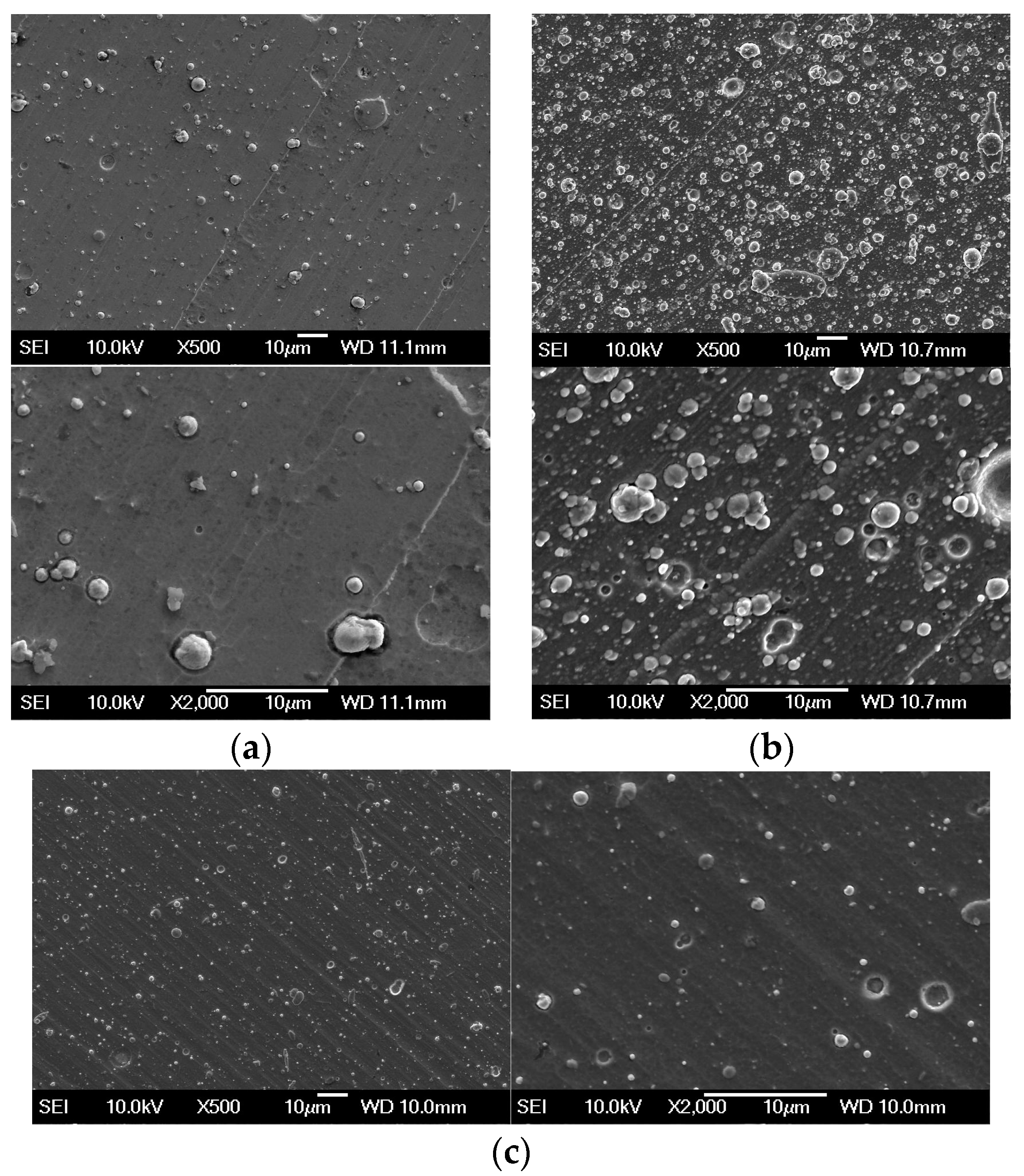
Globulitic particles were detected on the surface of PVD coatings after deposition; see Figure 2. In these globulitic particles, zirconium in the ZrN coating, titanium in the TiCN MP coating and chromium in the CrN coating were detected by qualitative EDX microanalysis. The presence of the globulitic formations, so-called macroparticles is directly related to the technology of cathodic arc sputtering. The number and the size of macroparticles is mainly affected by the deposition parameters used for the individual types of coatings, the appliance and the type of coated material. The macroparticles were metallic, formed at the end of the deposition process according to the type of PVD coating.
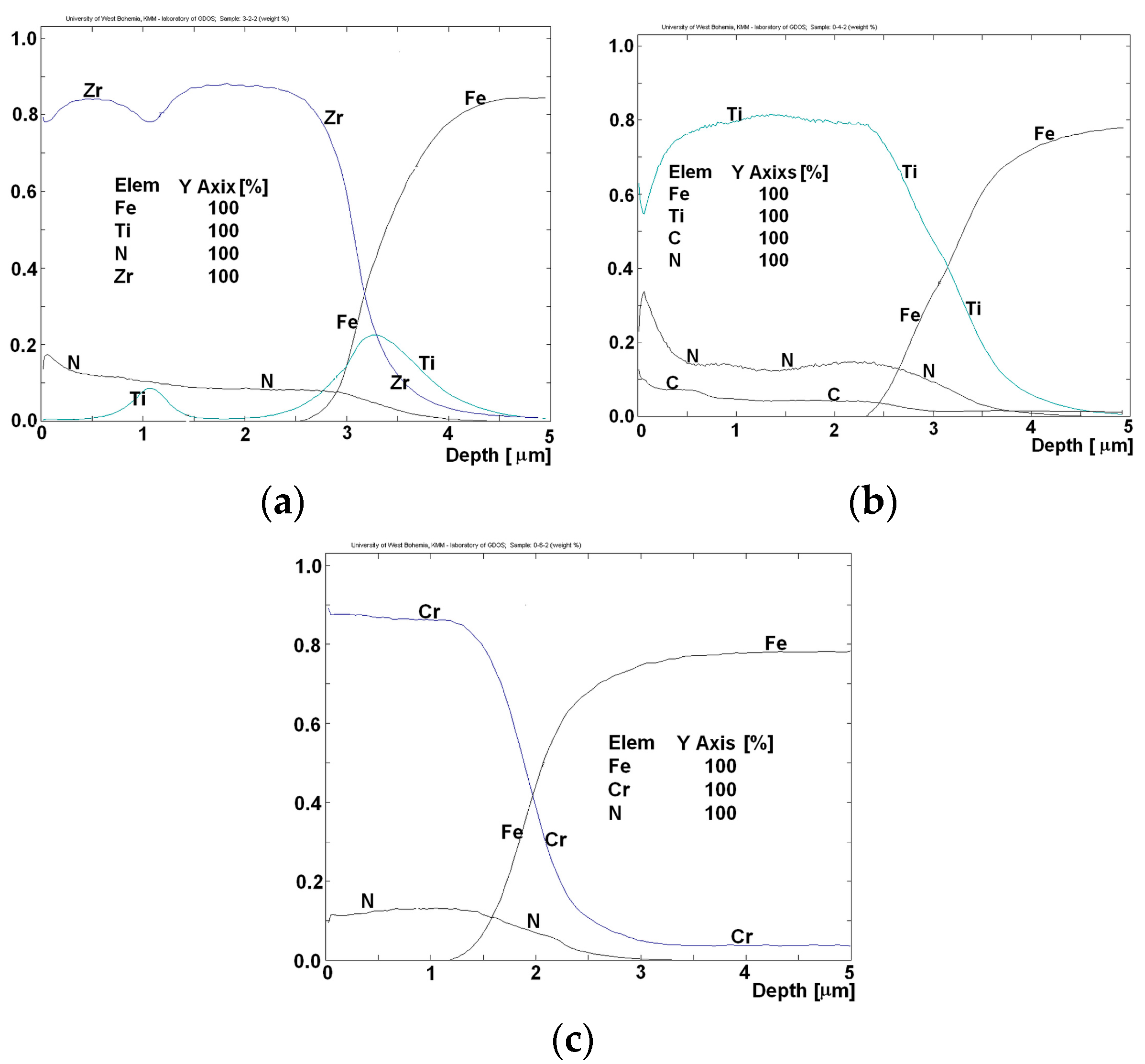
The Glow Discharge Optical Emission Spectroscopy (GDOES) method was used to measure a deep concentration profile of the elements Zr, Ti, Al, N and C in the PVD coatings. The changes in the concentrations of these elements were expressed graphically up to the depth of 5 μm. Only in the ZrN coating, titanium was present in one third of the coating’s thickness and on the border between the PVD coating and the surface of the tool (Figure 3).
At the boundary between the substrate and the PVD coating, titanium forms an interlayer whose purpose is to increase the adhesion of the PVD coating. Face Center Cubic (FCC) structure was detected by Grazing incidence (GI) X-ray radiation in all PVD coatings (Figure 4, Table 2).
The PVD coating thickness was measured on each sample by the Calotest method (Table 3). The coating thicknesses depend on the technology of the deposition process, position and shape of the tool in the deposition chamber. Allowed deviations from the prescribed value were ±10%.
The highest values of the indentation hardness HIT and the indentation module E were measured in case of the TiCN MP coating (Table 3).
The surface microgeometry parameters (Ra, mean arithmetic deviation; Rz, maximum profile height; Rq, mean square deviation of the profile) were determined according to ISO 4287 standard (Table 4). The difference in Ra values of all coatings in the direction of grinding (marked as “L” in Table 4) and perpendicularly to the grinding direction (marked as “T” In Table 4) measured by the contact profilometer was from 0.02 to 0.08 µm.
The difference in Ra values measured by an optical profilometer perpendicularly to the direction of grinding and in the direction of grinding was from 0.09 to 0.16 µm for all coatings. The difference in the values of Sa and Ra (measured perpendicularly to the direction of grinding) was from 0.01 to 0.05 µm. The difference of the values of parameters Sa measured according to ISO 25178 and ISO 4287 (Table 4) on the surfaces of all PVD coatings was up to 0.05 µm.
The friction coefficients between the steel ball and PVD coatings ZrN, CrN and TiCN MP were measured using a CSM HT tribometer. All the experiments were performed with the following tribotest parameters: the temperature of 20 ± 2 °C, the beads made of steel grade Cr100, the relative speed of 10 cm/s, normal load of 4 N. Each sample was measured three times (Table 5).
The average value of the coefficient of friction (µ-mean) was 0.594 for ZrN coating, 0.663 for TiCN MP coating and 0.676 for CrN coating.
3.2. Clinched Steel Sheets
The optical emission spectroscopy (OES) method was used for measuring the chemical composition of microalloyed steel sheets H220PD + Z100MBO. The analysis focused on the determination of the concentration of major alloying elements and accompanying elements (Table 6). The measured values are consistent with the chemical composition reported by the steel producer.
The directional values of the mechanical properties (Rp0.2: alternative yield point, Rm: tensile strength, Ag: uniform elongation, Agt: total elongation at maximum load, A80: elongation at fracture) of the tested steel sheets H220PD + Z100MBO were obtained from the tensile test according to STN EN ISO 6892-1 standard (Table 7).
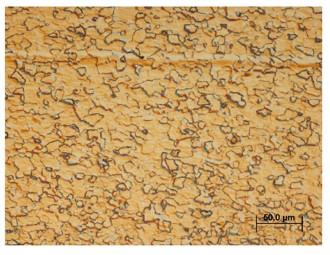
The steel sheet H220PD + Z100MBO of 0.78 mm thickness was microalloyed with Ti and Nb with the carbon concentration of 0.004 wt % and the silicon concentration of 0.10 wt %. The morphology of the surface of hot-dip galvanized steel sheets H220PD + Z100MBO was stochastic, with shallow dents of irregular shape in the zinc coating (Figure 5a). The sheet was hot-dip galvanized with the thickness of zinc coating of 10 µm on both sides. (Figure 5b). The GDOES analysis of the hot-dip galvanized layer detected aluminum in the zinc coating as well as at the boundary between the zinc layer and the steel underlying material of the H220PD + Z100MBO. The addition of aluminum to the zinc bath at the concentrations of 3–5% decelerates the growth kinetics of intermetallic phases based on Fe-Zn, affecting the growth of coating grains [61]. The microstructure of the H22PD + Z100MBO steel sheets was ferritic-cementitious (Figure 6).
The contact profilometer SJ-201 was used to determine the qualitative parameters that characterize the surface microgeometry of the processed sheets. The surface parameters (Ra: arithmetic deviation; Rz: maximum profile height; Rq: mean square deviation of the profile) were determined according to ISO 4287 standard in the direction of sheet rolling and perpendicularly to the direction of sheet rolling; see Table 8.
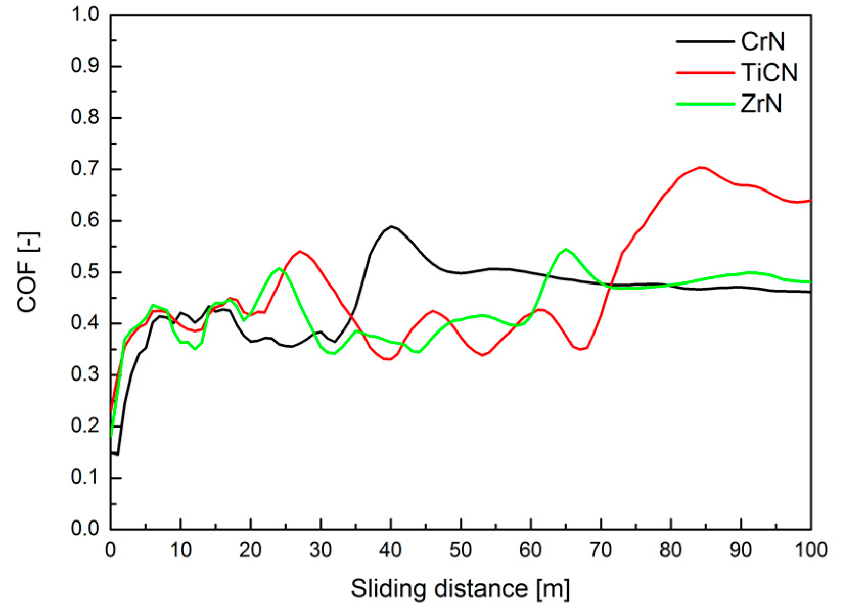
The simulation of the clinching process of hot-dip galvanized steel sheets with the PVD coated tools (punch and die) required obtaining the qualitative information on changes in friction coefficient during the first cycles of clinching. The measurements of friction coefficients between beads covered with ZrN, TiCN MP and CrN coatings (deposited by LARC technology) and hot-dip galvanized coating on H220PD + Z100 MBO sheets were measured using a CSM HT tribometer. All the experiments were performed at a temperature of 20 ± 2 °C. Each sample was measured three times. The following tribotest parameters were used: radius 3.5 mm, normal load of 5 N, total test distance of 100 m. The radius of tribological track for all the balls covered with CrN, ZrN and TiCN MP coatings was 3.5 mm. The relative speed of balls considering the galvanized sheet was 0.1 m/s. The average values of coefficient of friction (COF) was: 0.4 for ZrN and TiCN MP coating and 0.5 for CrN coating (Figure 7). The measured values of the friction coefficient provided qualitative information on the changes of the friction coefficient during the first cycles of clinching.
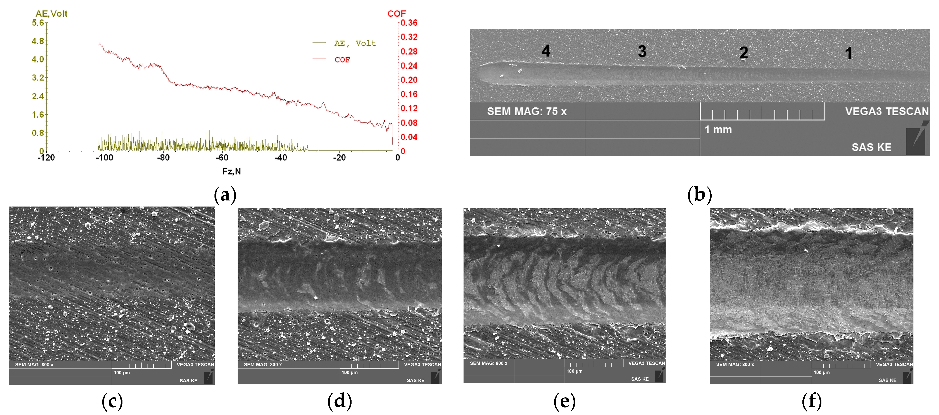
Qualitative information on the adhesion of PVD coatings of ZrN, CrN and TiCN MP deposited on test specimens was obtained by a Micro-Scratch test with a linear increase of normal force Fz. The test conditions were as follows: Rockwell indenter, max. normal force Fz = −120 N, speed of movement of the sample under indenter = 0.01 mm/s. For all coatings, the acoustic emission (AE) increased at normal force Fz 30 to 40 N. A scanning electron microscope was used to monitor the failures of PVD coatings in the scratch test.
The course of acoustic emission signal recorded during the scratch test showed an increase in the dependence on the normal force for the ZrN and CrN coatings deposited on the underlying material 1.3343/55 HRC.
The ZrN coating in this test showed an increase in the acoustic emission at 10–15 N; this can indicate a higher value of hardness of the surface layer and thereby its higher brittleness, which usually leads to a significant increase in the acoustic emission even if a small failure occurs (Figure 8).
At the higher normal forces, only a little cohesive spallation along the scratch-track borders as well as minor wear at the bottom of scratch-track occurred (tensile type Hertzian cracks within the scratch track). An intensive decrease of the signal level AE was about 85 N at normal force of about 85 N. At the normal value of Fz = 85 N, the coefficient of friction increased; the indenter was in a contact with the underlying material.
The signal of acoustic emission of TiCN MP coating gradually increased to the steady state (lower expansion of coating failures). The low intensity of AE signal in all TiCN coatings deposited on the base material 1.3343/55 HRc was measured and showed no step changes during the increase of normal force (Figure 9). In terms of morphological features of failure of scratch border and centerline track, only a small cohesive spallation along the scratch-track borders as well as minor wear at the bottom of scratch-track occurred at the higher normal forces.
The CrN coating showed a low level of the acoustic emission signal for the normal force values of 20–30 N (Figure 10). At the higher normal forces, only a little cohesive spallation along the scratch-track borders as well as minor wear at the bottom of scratch-track occurred. An intensive decrease of the AE signal level at the normal force of about 65 N was measured; the indenter was in a contact with the underlying material.
3.3. Finite Element Analysis of The Clinching Process
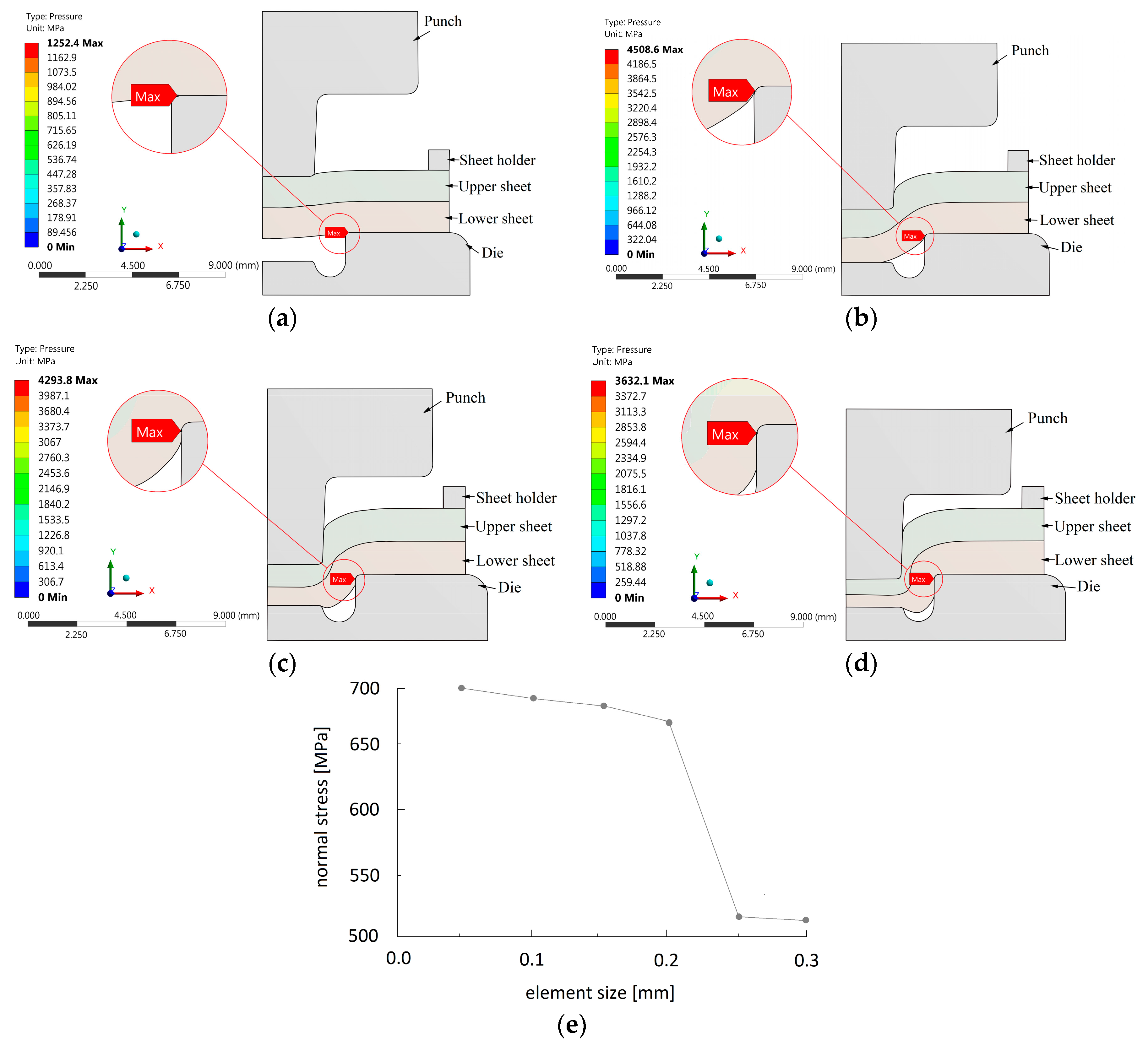
The results of finite element simulation of the clinching process are scoped into a single body to gain clear information about the maximum stress and contact pressure levels and also their localization in the punch or the die. Figure 11 shows the evolution and peak values of contact pressure during individual joining stages of the clinching process with a rigid die. The images show the position of peak values of contact pressure in the die-lower sheet contact area. Nonlinear adaptive region does not work along with contour scoping; hence individual images show only the location of maximum values of contact pressure.
Figure 11e shows the mesh sensitivity graph produced for the simulation of clinching. Its vertical axis represents the maximum level of normal stress in X direction. The horizontal axis represents the element size used for die, both steel sheets and the punch. The position of the peak values of normal stress did not change across individual element sizes and was localized at the area of lower steel sheet. Totally 6 calculations were carried out. Elements sizes ranged from 0.3 mm (5 elements across the thickness of the sheet) to 0.05 mm (30 elements across the thickness of the sheet). It was determined by the mesh sensitivity analysis that simulation gives stable results when element size of 0.2 mm is used. However, some divergence behavior of the analysis was encountered due to coarse discretization of the geometrical model. At this point, finer mesh should be used, or more sub-steps are required to aid the convergence behavior of the simulation. Very fine mesh (size of 0.1 or 0.05 mm) only extends the computational time due to large amount of nodes and enlarges the disc size of the files created.
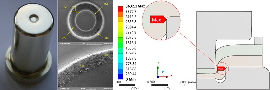
Contact pressure was evaluated in the die. Hence body scoping was chosen and focused to both joining tools. Due to the utilization of the so-called nonlinear adaptive region, it is not possible to achieve full-featured results; only the localization of maximum and minimum values of contact pressure is possible. The results of contact pressure evaluation show that the maximum contact pressure (4508.6 MPa) values occur at the radius of the surrounding of the cavity (ROD) area of die in the initial state of joint forming process known as drawing. Note that the contact pressure is calculated only for bodies in direct contact. When increasing the force needed for joint forming process, the values of contact pressure also increase. The position of the maximum values of the contact pressure (4508.6 MPa) changes from ROD area of the die to the VD area of the die. Further joining stages show no change to the position of maximum values of contact pressure. Similar values of contact pressure were identified for the punch.
The last result evaluated by finite element analysis was the material flow of both joined sheets. Only the steel sheets were scoped during the evaluation of this result. Figure 12 shows the total deformation of both sheets in the individual joint forming process stages.
Note that these results are converted into vector plots. These plots show that material flows downwards towards the die cavity during the initial stages of the joint forming process (drawing and compression). After the material reaches the die anvil, it starts (or tends to) to flow in the lateral direction into the die groove. This stage is known as the filling. The forming process of a clinching joint ends at the clinching stage, when both joined materials completely fill the die groove and the so-called interlock is formed in the neck area of joint.
3.4. The Wear of the Shaped Surface of the Die
FEM analysis localized the area on the shaped part of the die, in which high contact pressure values (Figure 11a–d) and a relatively intensive flow of the joined material (Figure 12a–d) occurred during the clinching process. According to the FEM analysis, surface wear can be expected on the shaped part of the die’s surface. The experimental verification of the prediction of the start of the wear cycle was performed by clinching 300 samples of hot-dip galvanized sheets.
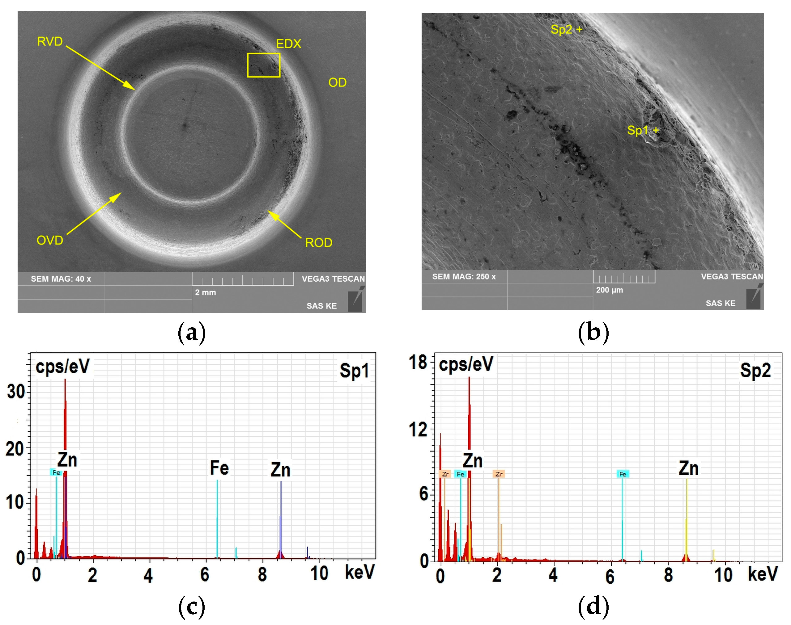
The morphology and the integrity of all PVD coatings was tested and evaluated in the areas of the shaped surface (Figure 13a, Figure 14a and Figure 15a): VD: the top of the cavity, RVD: the radius of the top of the cavity, OD: the surrounding of the cavity, ROD: the radius of the surrounding of the cavity, OVD: the surrounding of the top of the cavity. After creating 300 clinched joints of hot-dip galvanized H220PD + Z100MBO sheets, the violation of surface integrity of CrN and ZrN coatings appeared in the shaped part of the die marked as ROD (Figure 13a,b and Figure 14a,b). The surface integrity violation was localized within the whole radius R = 0.3 mm and the adjacent cylindrical surface (pointing at an angle of 3°) to a depth of about 200 µm. Zinc and iron were detected in the radius area R = 0.3 mm by qualitative EDX microanalysis (Figure 13c,d and Figure 14c,d). It is due to local galling of the zinc coating on the surface of the die in the radius area R = 0.3 mm and the violation of surface integrity. No globulitic microparticles were observed on the entire surface of the shaped part of the die.
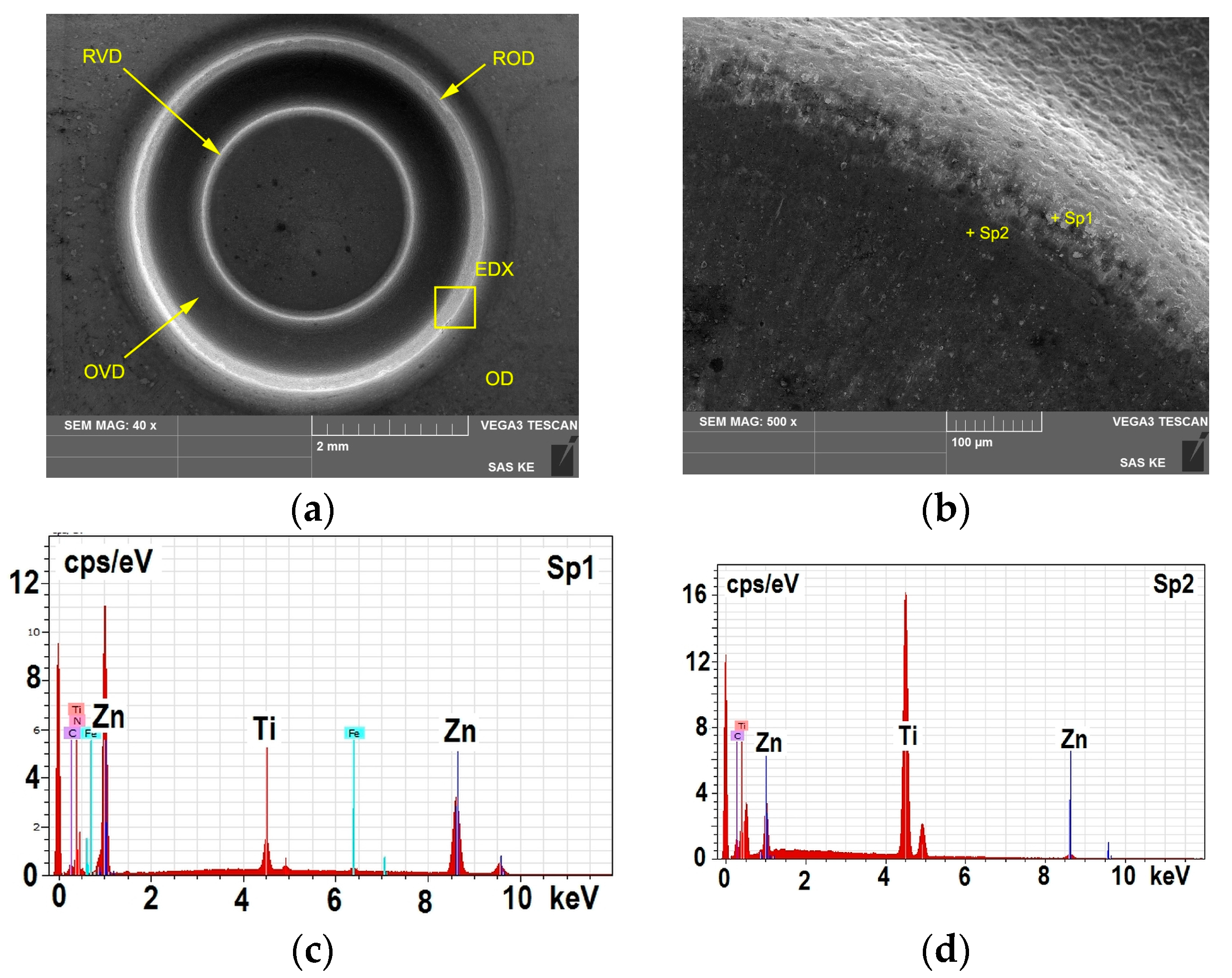
In the die covered with the PVD coating TiCN MP, no surface integrity violation on the entire surface of the shaped part of the die cavity was detected (Figure 15a,b). The qualitative EDX microanalysis detected titanium and traces of zinc in the ROD area. Iron and alloying elements from the material of the die were not detected. No globulitic microparticles or surface integrity violation of TiCN MP coating was present on the entire surface of the die.
The resistance of PVD coatings on clinching tools is determined by the physical and chemical properties of the entire system consisting of the coated tool, sheets that are being joined and the environment in which the process is carried out. Out of the properties of PVD coatings, mechanical and adhesive properties play a critical role. During the clinching process, the PVD coated tools are repeatedly mechanically loaded and the process is time-dependent. The individual PVD failure mechanisms then vary in intensity depending on the number of clinched joints produced and interact mutually. The failure is usually located in the areas near the surface of the active parts of the tools where the maximum mechanical stresses are at the macro and micro-plane levels. The macrostresses are determined by the overall distribution of mechanical stresses at each clinching cycle. The internal mechanical microstress levels depend on the microstructure of the system tool-coating as well as on the stress value and orientation [39,41].
After the clinching process, certain zones with the adhesive zinc stuck to the shaped part of die surface (galling) were observed. The adhesive galls occurred on the shaped part of the die, mainly in the radius R = 0.3 mm (ROD) and in the adjacent cylindrical surface near the radius R = 0.2 mm. The position of the zinc galls on the shaped surface of the die followed the change of the location of maximum pressure during the clinching process, which moved towards the cylindrical surface of the die ϕ 5 mm (Figure 11), according to the results of FEM analysis. The material flow of the joined materials was directed towards the die cavity (Figure 12). The PVD coating TiCN MP remained intact on the entire surface of the die and the PVD coatings ZrN and CrN were worn in the ROD area of the die.
The surface microgeometry of the die was the result of the technology of final treatment of the die surface and the conditions of PVD coating deposition process [62]. The surface integrity violation and formation of adhesive galls occurred in the ROD area and the adjacent cylindrical surface of the die cavity. As a result of the high contact pressure and the material flow due to the shape of the die, the convex shape unevennesses of the surface of the PVD coating were potential locations, in which the zinc was compacted during the clinching process. With the subsequent clinched joint, an adhesive joint may be formed between the zinc compacted in the shape unevennesses of PVD coating and zinc coating. This mechanism could result in the formation of repeated adhesive joints of galled zinc and zinc coating in the clinched joined steel sheets.
The physical-metallurgical nature of zinc transmission (galling) from the zinc layer to the surface of the formed part of the tool covered with PVD coating was determined by the physical-metallurgical properties of the zinc layer and PVD coating, topography and microgeometry of the surface of the zinc layer and PVD coating, the actual state of mechanical stresses in the formed sheet and tool and the plastic flow of the formed material. It is a complex, dynamically interconnected system of interaction of the surfaces of two bodies [44,48,62,63,64].
The wear process can be understood as an implicit function of several variables that do not have to be mutually dependent. It is possible to experimentally determine only an isolated group of physical and material parameters that characterize PVD coatings and hot-dip galvanized thin steel sheets. The wear of the die is then determined by the following: the topography (clusters) (Figure 2) and the microgeometry of the PVD coatings (Ra, Sa) and the direction of final grinding of the die surface; see Table 4), the coefficient of friction between the PVD coating and the hot-dip galvanized steel sheet (Table 5), the rigidity characterized by the modulus of elasticity (E) and hardness (HIT) of PVD coatings (Table 3), mechanical stress in the joined hot-dip galvanized steel sheets, its flow over the die surface (Figure 11 and Figure 12) and the roughness of the hot-galvanized sheets (Table 8). The information about the adhesion of PVD coatings to the steel substrate and the delamination resistance of the multilayer coating (MP) was obtained by a scratch test. The level of acoustic emission (AE) provided information about the delamination resistance of PVD coatings (Figure 8, Figure 9 and Figure 10). The zinc can be stuck into the delaminated PVD coating during the flow of hot-dip galvanized steel sheet in the clinching process. In repeated clinching operation the stuck zinc acts as a wedge, i.e. it multiplies the failure of the die surface (Figure 13, Figure 14 and Figure 15).
4. Conclusions
Clinching is one of the most widely used mechanical joining methods in sheet metal construction applications. Various materials including galvanized steel sheets or non-ferrous sheets are joined by this method and thereby affecting the lifetime of the active parts of the clinching tool, the punch and the die. PVD coatings are used to decrease the wear of clinching tools. The degradation process of the cavity of the shaped part of the die during the clinching process is a superposition of multiple degradation mechanisms, prediction of which is demanding and complicated. One possibility is to utilize the FEM analyses of the clinching process.
FEM analysis identified the shaped part of the die ROD (R = 0.3 mm) and the segment of cylindrical surface of the die cavity ϕ 5.0 mm as areas in which there is a high contact pressure and a relatively intensive flow of the clinched material during the clinching process. The experimental verification of the prediction about the start of the wear cycle was performed by clinching 300 samples of hot-dip galvanized sheets.
After clinching the steel sheets, zones with zinc galls were observed in the shaped part of the die ROD (R = 0.3 mm) and in the cylindrical surface of die cavity ϕ 5.0 mm. The position of adhesive zinc galls on the shaped die surface followed the change of the location of maximum pressure during the clinching process, which moved towards the cylindrical surface of the die ϕ 5 mm. Out of the three types of PVD coating, the TiCN MP coating was intact on the entire surface of the die and the coatings ZrN and CrN were worn in the ROD area of the die. The wear resistance of PVD coatings mostly correlated with the indentation hardness values. The PVD coating TiCN MP had an indentation hardness value of 1.76 times higher than the values of ZrN coating and 1.89 times higher than the value of CrN coating.
Acknowledgments
The authors are grateful for the support of experimental works to Slovak Research and Development Agency under project APVV-14-0834 “Increasing the quality of cut-outs and effectiveness of cutting electric sheets” and grant agency for the support of the project VEGA 1/0441/17 “Application of high-strength materials for exterior car body parts”.
Author Contributions
Miroslav Džupon performed GD-OES method and Calotest method, Ľuboš Kaščák performed the clinching of steel sheets and wrote the paper, Emil Spišák conceived and designed the experiments, René Kubík performed the simulation of clinching process, Janka Majerníková analyzed the data.
Conflicts of Interest
The authors declare no conflict of interest.
References and Note
- Chen, C.; Zhao, S.; Cui, M.; Han, X.; Fan, S.; Ishida, T. An experimental study on the compressing process for joining Al6061 sheets. Thin Walled Struct. 2016, 108, 56–63. [Google Scholar] [CrossRef]
- Jiang, T.; Liu, Z.X.; Wang, P.C. Quality inspection of clinched joints of steel and aluminum. Int. J. Adv. Manuf. Technol. 2015, 76, 1393–1402. [Google Scholar] [CrossRef]
- Barnes, T.A.; Pashby, I.R. Joining techniques for aluminium spaceframes used in automobiles: Part I—Solid and liquid phase welding. J. Mater. Process. Technol. 2000, 99, 62–71. [Google Scholar] [CrossRef]
- Pedreschi, R.F.; Sinha, B.P. An experimental study of cold formed steel trusses using mechanical clinching. Constr. Build. Mater. 2008, 22, 921–931. [Google Scholar] [CrossRef]
- Mucha, J.; Kaščák, Ľ.; Spišák, E. Joining the car-body sheets using clinching process with various thickness and mechanical property arrangements. Arch. Civ. Mech. Eng. 2011, 11, 135–148. [Google Scholar] [CrossRef]
- Kaščák, L.; Spišák, E.; Mucha, J. Mechanical joining of various materials by clinching method. Key Eng. Mater. 2015, 662, 205–208. [Google Scholar] [CrossRef]
- Mucha, J.; Kaščák, L.; Spišák, E. The experimental analysis of forming and strength of clinch riveting sheet metal joint made of different materials. Adv. Mech. Eng. 2013, 5, 848973. [Google Scholar] [CrossRef]
- Israel, M.; Mauermann, R.; Schellnock, J. Thick sheet clinching-joining up to 20 mm total thickness. Adv. Shipp. Ocean Eng. 2013, 2, 1–10. [Google Scholar]
- Zhao, L.; He, X.C.; Lu, Y. Study on clinching of titanium alloy. Appl. Mech. Mater. 2014, 633–634, 86–89. [Google Scholar] [CrossRef]
- He, X.; Zhang, Y.; Xing, B.; Gu, F.; Ball, A. Mechanical properties of extensible die clinched joints in titanium sheet materials. Mater. Des. 2015, 71, 26–35. [Google Scholar] [CrossRef]
- Lee, S.H.; Lee, C.J.; Lee, K.H.; Lee, J.M.; Kim, B.M.; Ko, D.C. Influence of tool shape on hole clinching for carbon fiber-reinforced plastic and SPRC440. Adv. Mech. Eng. 2014, 6, 810864. [Google Scholar] [CrossRef]
- Lambiase, F.; Di Ilio, A. Mechanical clinching of metal–polymer joints. J. Mater. Process. Technol. 2015, 215, 12–19. [Google Scholar] [CrossRef]
- Lambiase, F. Mechanical behaviour of polymer–metal hybrid joints produced by clinching using different tools. Mater. Des. 2015, 87, 606–618. [Google Scholar] [CrossRef]
- Behrens, B.A.; Rolfes, R.; Vucetic, M.; Reinoso, J.; Vogler, M.; Grbic, N. Material modelling of short fiber reinforced thermoplastic for the FEA of a clinching test. In Proceedings of the International Conference on Manufacture of Lightweight Components—ManuLight 2014, Dortmund, Germany, 3–4 April 2014. [Google Scholar] [CrossRef]
- Lambiase, F.; Durante, M.; Di Ilio, A. Fast joining of aluminum sheets with Glass Fiber Reinforced Polymer (GFRP) by mechanical clinching. J. Mater. Process. Technol. 2016, 236, 241–251. [Google Scholar] [CrossRef]
- Bartczak, B.; Mucha, J.; Trzepieciński, T. Stress distribution in adhesively-bonded joints and the loading capacity of hybrid joints of car body steels for the automotive industry. Int. J. Adhes. Adhes. 2013, 45, 42–52. [Google Scholar] [CrossRef]
- Eshtayeh, M.M.; Hrairi, M. Recent and future development of the application of finite element analysis in clinching process. Int. J. Adv. Manuf. Technol. 2016, 84, 2589–2608. [Google Scholar] [CrossRef]
- Chen, C.; Zhao, S.; Cui, M.; Han, X.L.; Ben, N. Numerical and experimental investigations of the reshaped joints with and without a rivet. Int. J. Adv. Manuf. Technol. 2017, 88, 2039–2051. [Google Scholar] [CrossRef]
- He, X. Recent development in finite element analysis of clinched joints. Int. J. Adv. Manuf. Technol. 2010, 48, 607–612. [Google Scholar] [CrossRef]
- Carboni, M.; Beretta, S.; Monno, M. Fatigue behaviour of tensile-shear loaded clinched joints. Eng. Fract. Mech. 2006, 73, 178–190. [Google Scholar] [CrossRef]
- De Paula, A.A.; Aguilar, M.T.P.; Pertence, A.E.M.; Cetlin, P.R. Finite element simulations of the clinch joining of metallic sheets. J. Mater. Process. Technol. 2007, 182, 352–357. [Google Scholar] [CrossRef]
- Strandberg, O.; Lennblad, J.; Hammarstrom, L. FE modeling of the clinch joining process. In Proceedings of the International Body Engineering IBEC, Detroit, MI, USA, 26–29 September 1994. [Google Scholar]
- Varis, J.P. The suitability of clinching as a joining method for high-strength structural steel. J. Mater. Process. Technol. 2003, 132, 242–249. [Google Scholar] [CrossRef]
- Dean, A.; Sahraee, S.; Reinoso, J.; Rolfes, R. Finite deformation model for short fiber reinforced composites: Application to hybrid metal-composite clinching joints. Compos. Struct. 2016, 151, 162–171. [Google Scholar] [CrossRef]
- Hamel, V.; Roelandt, J.M.; Gacel, J.N.; Schmit, F. Finite element modeling of clinch forming with automatic remeshing. Comput. Struct. 2000, 77, 185–200. [Google Scholar] [CrossRef]
- Oudjene, M.; Ben-Aeyd, L. On the parametrical study of clinch joining of metallic sheets using the Taguchi method. Eng. Struct. 2008, 30, 1782–1788. [Google Scholar] [CrossRef]
- Varis, J.P. The suitability of round clinching tools for high strength structural steel. Thin Walled Struct. 2002, 40, 225–238. [Google Scholar] [CrossRef]
- He, X.; Liu, F.; Xing, B.; Yang, H.; Wang, Y.; Gu, F.; Ball, A. Numerical and experimental investigations of extensible die clinching. Int. J. Adv. Manuf. Technol. 2014, 74, 1229–1236. [Google Scholar] [CrossRef]
- He, X.; Zhao, L.; Yang, H.; Xing, B.; Wang, Y.; Deng, C.; Gu, F.; Ball, A. Investigations of strength and energy absorption of clinched joint. Comput. Mater. Sci. 2014, 94, 58–65. [Google Scholar] [CrossRef]
- Ali, B.; Benabderrahmane, B. Finite element simulation of the hybrid clinch joining. Int. J. Adv. Manuf. Technol. 2017, 89, 439–449. [Google Scholar] [CrossRef]
- Lambiase, F.; Di Ilio, A. Damage analysis in mechanical clinching. J. Mater. Process. Technol. 2016, 230, 109–120. [Google Scholar] [CrossRef]
- Lambiase, F.; Di Ilio, A. Finite element analysis of material flow in mechanical clinching with extensible dies. J. Mater. Eng. Perform. 2013, 22, 1629–1636. [Google Scholar] [CrossRef]
- Yang, X.; Tong, Z.; Dai, X.; Zhang, F. Finite element analysis of punching bonding technology for automobile sheets. Automob. Technol. 2006, 10, 41–43. [Google Scholar]
- Mori, K.; Abe, Y.; Kato, T. Finite element simulation of plastic joining processes of steel and aluminum alloy sheets. In Proceedings of the 9th International Conference on Numerical Methods in Industrial Forming Processes, Porto, Portugal, 17–21 June 2007. [Google Scholar]
- Wang, L.; Wang, Y.; Zhang, W.Q.; Sun, X.G.; He, J.Q.; Pan, Z.Y.; Wang, C.H. Finite element simulation of stress distribution and development in 8YSZ and double-ceramic-layer La2Zr2O7/8YSZ thermal barrier coatings during thermal shock. Appl. Surf. Sci. 2012, 258, 3540–3551. [Google Scholar] [CrossRef]
- Śliwa, A.; Mikuła, J.; Gołombek, K.; Tański, T.; Kwaśny, W.; Bonek, M.; Brytan, Z. Prediction of the properties of PVD/CVD coatings with the use of FEM analysis. Appl. Surf. Sci. 2016, 388, 281–287. [Google Scholar] [CrossRef]
- Navinšek, B.; Panjan, P.; Cvelbar, A. Characterization of low temperature CrN and TiN (PVD) hard coatings. Surf. Coat. Technol. 1995, 74, 155–161. [Google Scholar] [CrossRef]
- Mylvaganam, K.; Chen, Y.; Liu, W.; Liu, M.; Zhang, L. Hard thin films: Applications and challenges. In Anti-Abrasive Nanocoatings—Current and Future Applications, 1st ed.; Aliofkhazraei, M., Ed.; Elsevier: Amsterdam, The Netherlands, 2015. [Google Scholar]
- Mohan, S.; Mohan, A. Wear, friction and prevention of tribo-surfaces by coatings/nanocoatings. In Anti-Abrasive Nanocoatings—Current and Future Applications, 1st ed.; Aliofkhazraei, M., Ed.; Elsevier: Amsterdam, The Netherlands, 2015. [Google Scholar]
- Vilaseca, M.; Pujante, J.; Ramírez, G.; Casellas, D. Investigation into adhesive wear of PVD coatedand uncoated hot stamping production tools. Wear 2013, 308, 148–154. [Google Scholar] [CrossRef]
- Kato, K. Wear in relation to friction—A review. Wear 2000, 241, 151–157. [Google Scholar] [CrossRef]
- Budinski, K. Incipient galling of metals. Wear 1981, 74, 93–105. [Google Scholar] [CrossRef]
- Wang, W.; Wang, K.; Zhao, Y.; Hua, M.; Wei, X. A study on galling initiation in friction coupling stretch bending with advanced high strength hot-dip galvanized sheet. Wear 2015, 328–329, 286–294. [Google Scholar] [CrossRef]
- Kim, H.; Sung, J.; Frank, E.; Goodwin, F.E.; Altan, T. Investigation of galling in forming galvanized advanced high strength steels (AHSSs) using the twist compression test (TCT). J. Mater. Process. Technol. 2008, 205, 459–468. [Google Scholar] [CrossRef]
- Podgornik, B.; Jerina, J. Surface topography effect on galling resistance of coated and uncoated tool steel. Surf. Coat. Technol. 2012, 206, 2792–2800. [Google Scholar] [CrossRef]
- Podgornik, B.; Hogmark, S.; Sandberg, O. Influence of surface roughness and coating type on the galling properties of coated forming tool steel. Surf. Coat. Technol. 2004, 184, 338–348. [Google Scholar] [CrossRef]
- Gåård, A. Influence of tool microstructure on galling resistance. Tribol. Int. 2013, 57, 251–256. [Google Scholar] [CrossRef]
- Sellgren, U.; Björklund, S.; Andersson, S. A finite element-based model of normal contact between rough surfaces. Wear 2003, 254, 1180–1188. [Google Scholar] [CrossRef]
- Van der Heide, E.; Schipper, D.J. Galling initiation due to frictional heating. Wear 2003, 254, 1127–1133. [Google Scholar] [CrossRef]
- Pulker, H.K.; Perry, A.J.; Berger, R. Adhesion. Surf. Technol. 1981, 14, 25–39. [Google Scholar] [CrossRef]
- Chalker, P.R.; Bull, S.J.; Rickerby, D.S. A review of the methods for the evaluation of coating-substrate adhesion. Mater. Sci. Eng. 1991, 140, 583–592. [Google Scholar] [CrossRef]
- Rickerby, D.S. A review of the methods for the measurement of coating-substrate adhesion. Surf. Coat. Technol. 1988, 36, 541–557. [Google Scholar] [CrossRef]
- Harry, E.; Ignat, M.; Pauleau, Y.; Rouzaud, A.; Juliet, P. Mechanical behaviour of hard PVD multilayered coatings. Surf. Coat. Technol. 2000, 125, 185–189. [Google Scholar] [CrossRef]
- Vereschaka, A.A.; Grigoriev, S.N. Study of cracking mechanisms in multi-layered composite nano-structured coatings. Wear 2017, 378, 43–57. [Google Scholar] [CrossRef]
- ISO 20502: Fine ceramics (advanced ceramics, advanced technical ceramics)-Determination of adhesion of ceramic coatings by scratch testing, 2005.
- Attar, F.; Johannesson, T. Adhesion evaluation of thin ceramic coatings on tool steel using the scratch testing technique. Surf. Coat. Technol. 1996, 78, 87–102. [Google Scholar] [CrossRef]
- Džupon, M.; Kaščák, L.; Németh, D.; Kubík, R. Failure of physical vapour deposition coating zirconium nitride on the punch of clinching tool. Acta Mech. Autom. 2016, 11, 143–149. [Google Scholar] [CrossRef]
- Kubík, R.; Kaščák, L.; Spišák, E. Wear of PVD coated tools for joining by clinching method. Koroze Ochrana Materialu 2016, 60, 154–161. [Google Scholar] [CrossRef]
- Breda, A.; Coppieters, S.; Debruyne, D. Equivalent modelling strategy for a clinched joint using a simple calibration method. Thin Walled Struct. 2017, 113, 1–12. [Google Scholar] [CrossRef]
- Eshtayeh, M.M.; Hrairi, M.; Mohiuddin, A.K.M. Clinching process for joining dissimilar materials: state of the art. Int. J. Adv. Manuf. Technol. 2016, 82, 179–195. [Google Scholar] [CrossRef]
- Fergus, J.W. The status of chemical sensors for hot-dip galvanization. JOM 1996, 48, 38–41. [Google Scholar] [CrossRef]
- Eriksson, J.; Olsson, M. Tribological testing of commercial CrN, (Ti,Al)N and CrC/C PVD coatings—Evaluation of galling and wear characteristics against different high strength steels. Surf. Coat. Technol. 2011, 205, 4045–4051. [Google Scholar] [CrossRef]
- Astarita, A.; Rubino, F.; Carlone, P.; Ruggiero, A.; Leone, C.; Genna, S.; Merola, M.; Squillace, A. On the improvement of AA2024 wear properties through the deposition of a cold-sprayed titanium coating. Metals 2016, 6, 185. [Google Scholar] [CrossRef]
- Wang, W.; Zheng, X.; Hua, M.; Wei, X. Influence of surface modification on galling resistance of DC53 tool steel against galvanized advanced high strength steel sheet. Wear 2016, 360–361, 1–13. [Google Scholar] [CrossRef]
Figure 1.
Clinching tool: (a) punch; (b) die; tool covered with (c) ZrN coating; (d) CrN coating and (e) TiCN MP coating. (unit: mm).
Figure 1.
Clinching tool: (a) punch; (b) die; tool covered with (c) ZrN coating; (d) CrN coating and (e) TiCN MP coating. (unit: mm).

Figure 2.
Surfaces of: (a) ZrN; (b) TiCN MP and (c) CrN coatings.

Figure 3.
Glow Discharge Optical Emission Spectroscopy (GD-OES) profile concentration analysis of coating: (a) ZrN; (b) TiCN MP and (c) CrN.
Figure 3.
Glow Discharge Optical Emission Spectroscopy (GD-OES) profile concentration analysis of coating: (a) ZrN; (b) TiCN MP and (c) CrN.

Figure 4.
GI qualitative X-ray analysis: (a) ZrN-FCC-Fm3m (255); (b) TiCN MP-FCC-Fm3m (255) and (c) CrN-FCC-Fm3m (255).
Figure 4.
GI qualitative X-ray analysis: (a) ZrN-FCC-Fm3m (255); (b) TiCN MP-FCC-Fm3m (255) and (c) CrN-FCC-Fm3m (255).
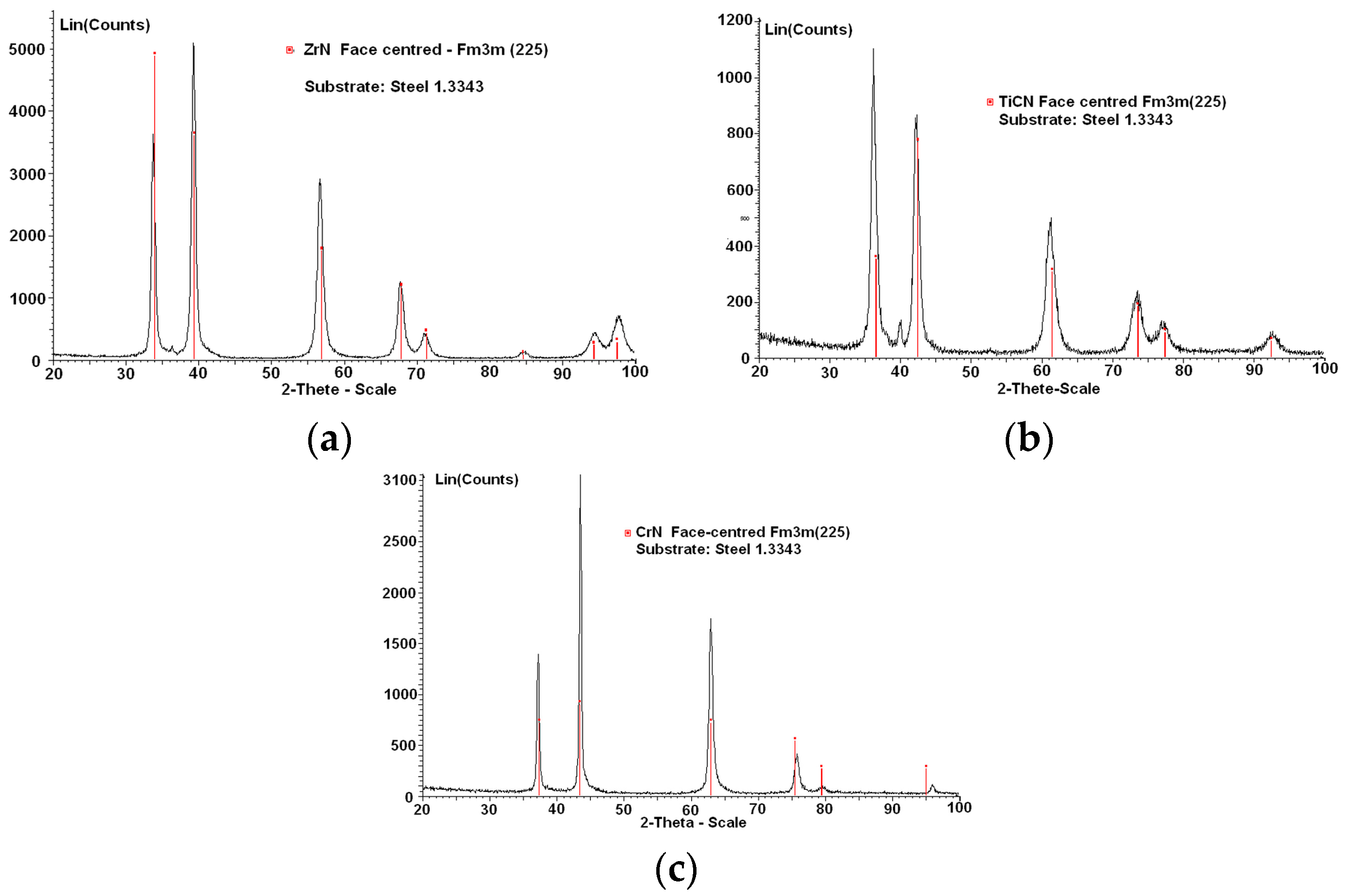
Figure 5.
(a) Stochastic morphology of the surface of hot-dip galvanized sheet H22PD + Z100MBO and (b) GD-OES analysis of hot-dip galvanized coating.
Figure 5.
(a) Stochastic morphology of the surface of hot-dip galvanized sheet H22PD + Z100MBO and (b) GD-OES analysis of hot-dip galvanized coating.
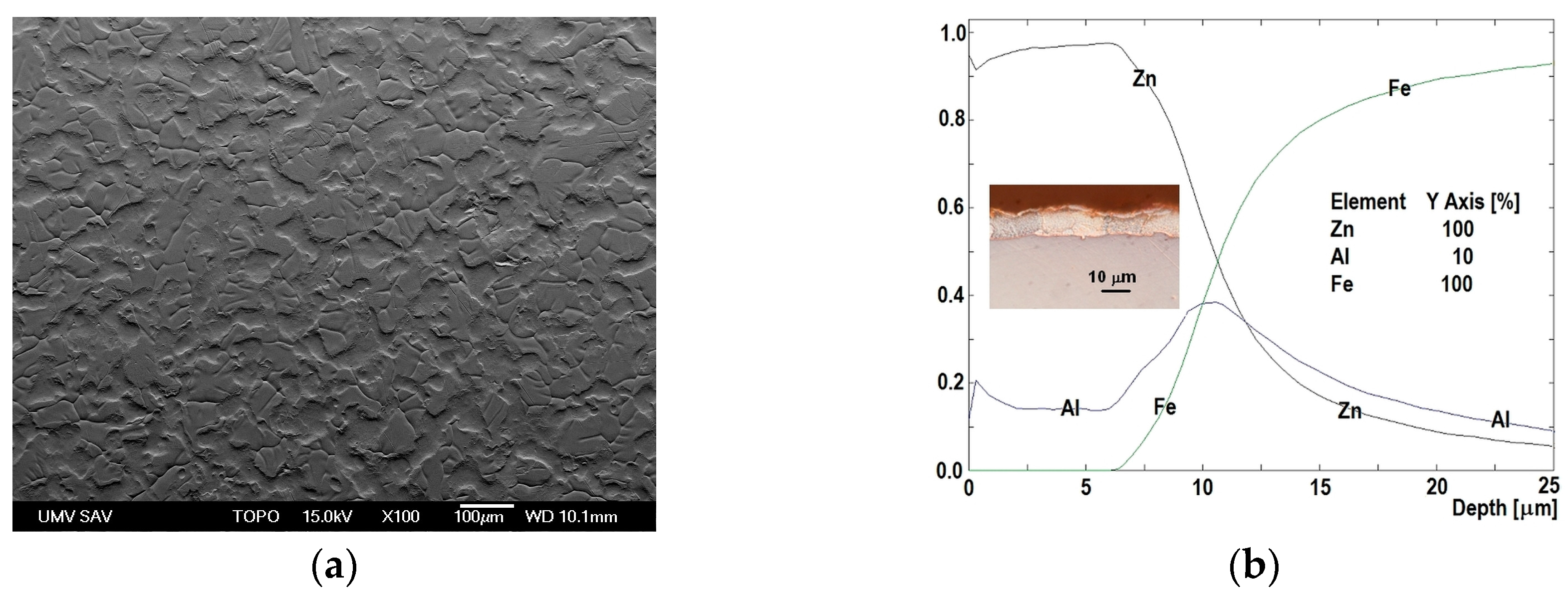
Figure 6.
Microstructure of H220PD + Z100MBO.

Figure 7.
Average values of friction coefficient in dependence on sliding distance.

Figure 8.
Acoustic emission of ZrN coating: (a) record AE-Fz, COF-Fz; (b) scratch–disposition and (c–f) detail of coating failure, position 1–4 respectively.
Figure 8.
Acoustic emission of ZrN coating: (a) record AE-Fz, COF-Fz; (b) scratch–disposition and (c–f) detail of coating failure, position 1–4 respectively.
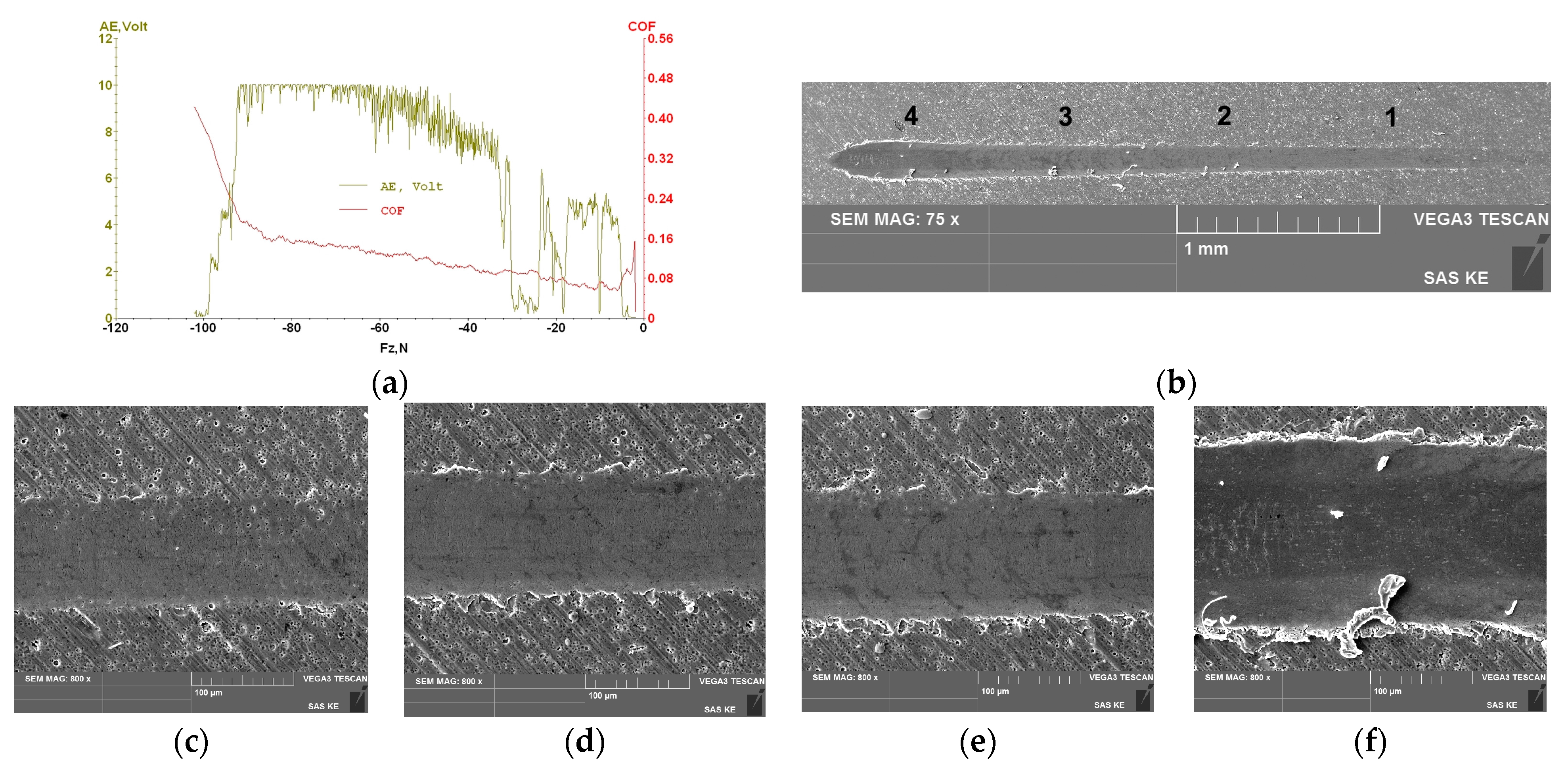
Figure 9.
Acoustic emission of TiCN coating: (a) record AE-Fz, COF-Fz; (b) scratch–disposition and (c–f) detail of coating failure, position 1–4 respectively.
Figure 9.
Acoustic emission of TiCN coating: (a) record AE-Fz, COF-Fz; (b) scratch–disposition and (c–f) detail of coating failure, position 1–4 respectively.

Figure 10.
Acoustic emission of CrN coating: (a) record AE-Fz, COF-Fz; (b) scratch–disposition and (c–f) detail of coating failure, position 1–4 respectively.
Figure 10.
Acoustic emission of CrN coating: (a) record AE-Fz, COF-Fz; (b) scratch–disposition and (c–f) detail of coating failure, position 1–4 respectively.
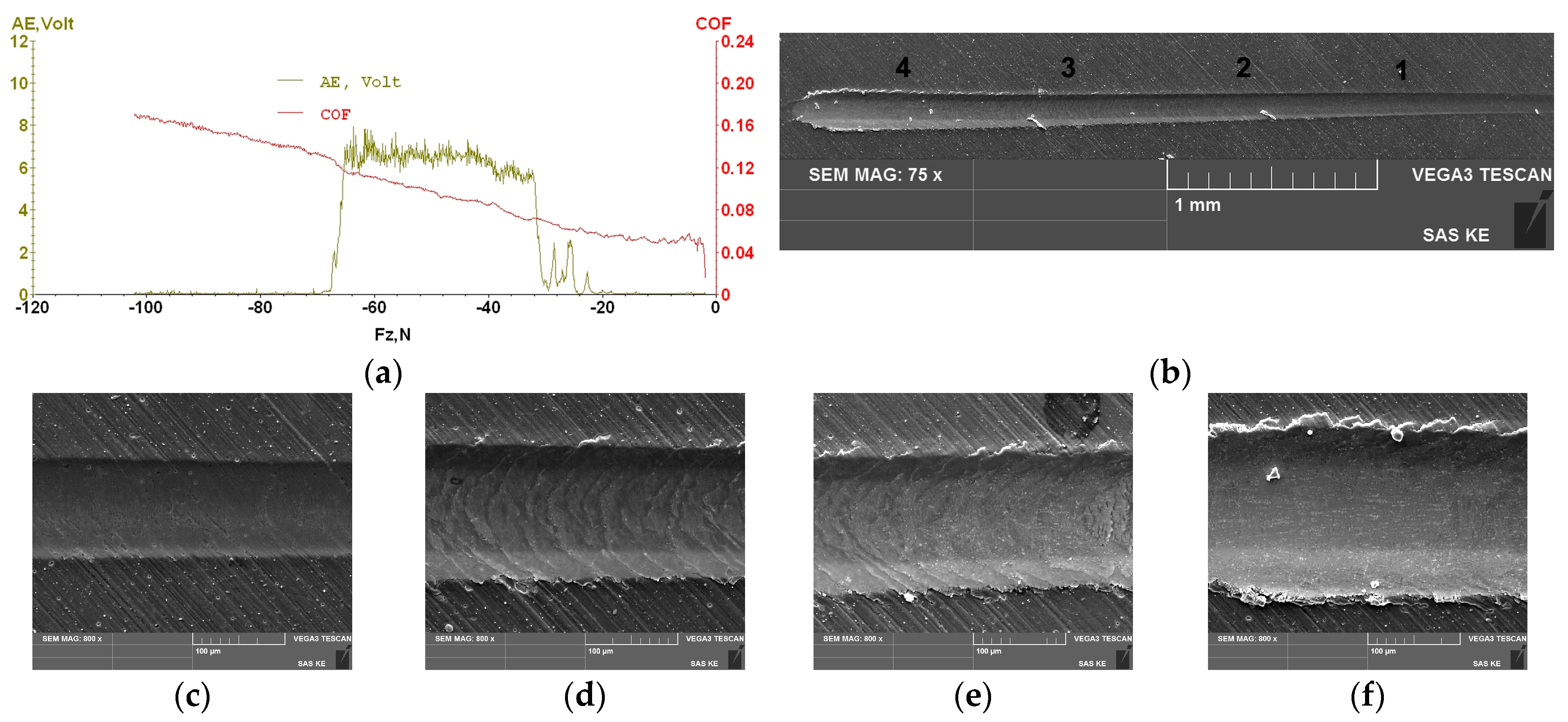
Figure 11.
Clinching process: (a) maximum contact pressure during drawing; (b) maximum contact pressure during compression; (c) maximum contact pressure during interlocking; (d) maximum contact pressure during backward extrusion; (e) normal stress–element size mesh sensitivity.
Figure 11.
Clinching process: (a) maximum contact pressure during drawing; (b) maximum contact pressure during compression; (c) maximum contact pressure during interlocking; (d) maximum contact pressure during backward extrusion; (e) normal stress–element size mesh sensitivity.

Figure 12.
Total deformation of both sheets in the individual joint forming process stages (the circle indicates the ROD area): (a) drawing phase; (b) compression phase; (c) interlocking phase; (d) backward extrusion phase.
Figure 12.
Total deformation of both sheets in the individual joint forming process stages (the circle indicates the ROD area): (a) drawing phase; (b) compression phase; (c) interlocking phase; (d) backward extrusion phase.
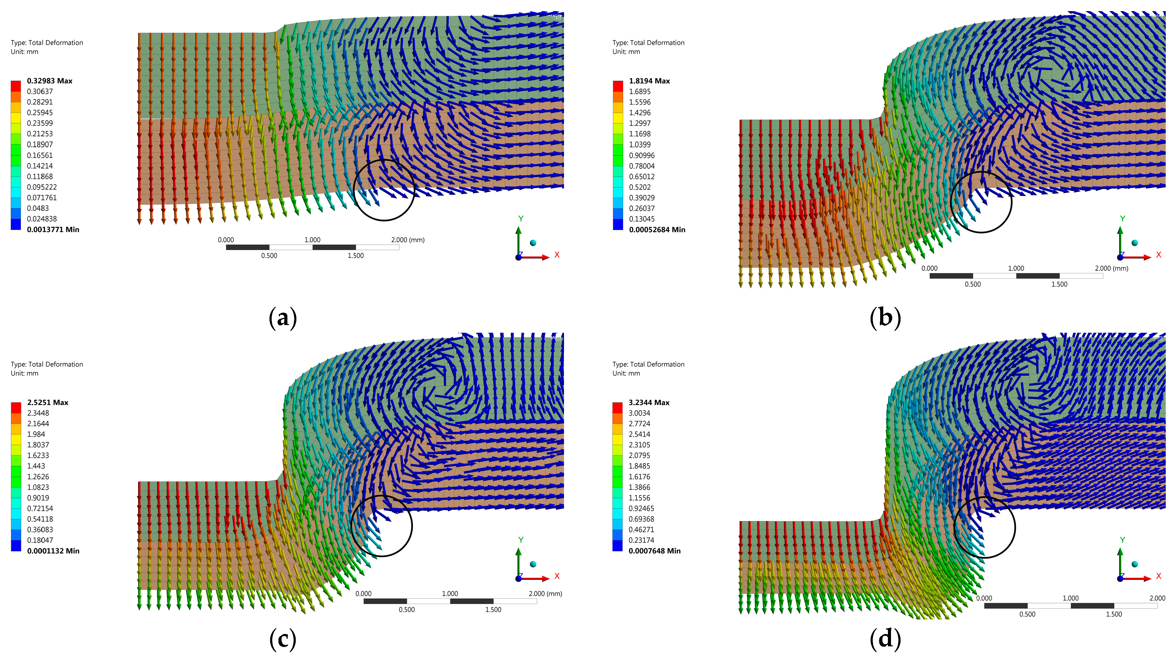
Figure 13.
CrN die-defect in the radius surrounding the cavity of the shaped surface ROD: (a) wear disposition of the shaped part of the die; (b) detail of ROD; (c) EDX microanalysis of Sp1 area; (d) EDX microanalysis of Sp2 area.
Figure 13.
CrN die-defect in the radius surrounding the cavity of the shaped surface ROD: (a) wear disposition of the shaped part of the die; (b) detail of ROD; (c) EDX microanalysis of Sp1 area; (d) EDX microanalysis of Sp2 area.
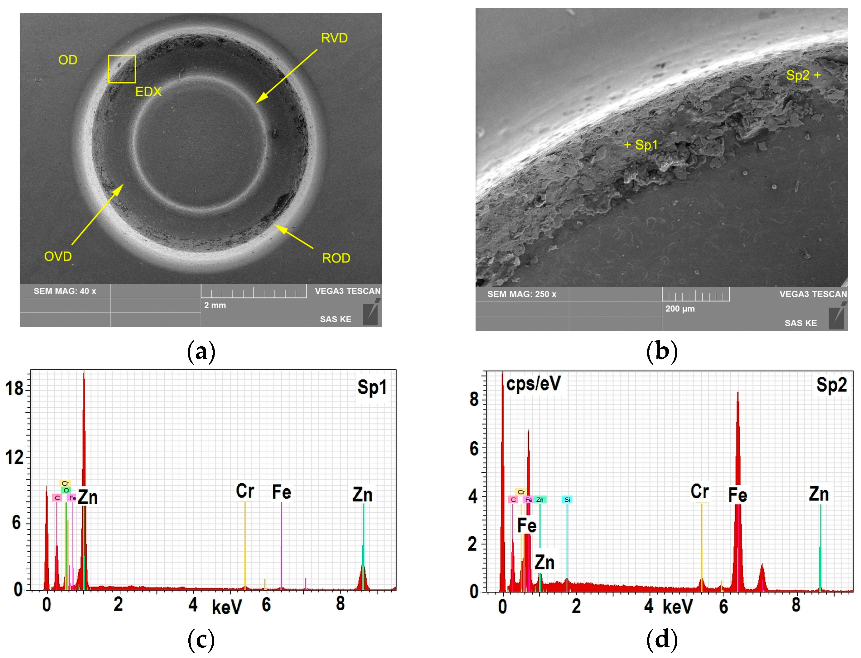
Figure 14.
ZrN die-defect in the radius surrounding the cavity of the shaped surface ROD: (a) wear disposition of the shaped part of the die; (b) detail of ROD; (c) EDX microanalysis of Sp1 area; (d) EDX microanalysis of Sp2 area.
Figure 14.
ZrN die-defect in the radius surrounding the cavity of the shaped surface ROD: (a) wear disposition of the shaped part of the die; (b) detail of ROD; (c) EDX microanalysis of Sp1 area; (d) EDX microanalysis of Sp2 area.

Figure 15.
TiCN MP die-defect in the radius surrounding the cavity of the shaped surface he radius of the surrounding of the cavity (ROD): (a) wear disposition of the shaped part of the die; (b) detail of ROD; (c) EDX microanalysis of Sp1 area; (d) EDX microanalysis of Sp2 area.
Figure 15.
TiCN MP die-defect in the radius surrounding the cavity of the shaped surface he radius of the surrounding of the cavity (ROD): (a) wear disposition of the shaped part of the die; (b) detail of ROD; (c) EDX microanalysis of Sp1 area; (d) EDX microanalysis of Sp2 area.


Table 1.
Input material properties for material model of deformable bodies.
| Material/Property | Elastic Portion | Plastic Portion | ||
|---|---|---|---|---|
| E (GPa) | v (-) | Rp0.2 (MPa) | ET (GPa) | |
| 1.3343 | 210 | 0.3 | 2030 | 10 |
| DP600 | 210 | 0.287 | 385 | - |
Table 2.
Lattice parameters, size of phase crystals.
| Coating | Phase | Lattice Parameter a (nm) | Error a (nm) | Cryst. Size (nm) | Error Cryst. Size (nm) |
|---|---|---|---|---|---|
| ZrN | ZrN | 0.45887 | 0.00003 | 9.7 | 0.2 |
| TiCN | TiCN | 0.42842 | 0.00004 | 6.8 | 0.2 |
| CrN | CrN | 0.41690 | 0.00003 | 15 | 3 |
“a” is a commonly used abbreviation of lattice parameter.
Table 3.
Average values of HIT and E of PVD coatings.
| Coating | Coating Thickness (μm) | Material of Tool | Tool Hardness (HRC) | HIT (GPa) | E (GPa) |
|---|---|---|---|---|---|
| ZrN | 2.96 | 1.3343 | 55–56 | 29 | 407 |
| TiCN MP | 3.35 | 1.3343 | 55–56 | 51 | 485 |
| CrN | 2.04 | 1.3343 | 55–56 | 27 | 325 |
Table 4.
Surface parameters of PVD coatings deposited on the material 1.3343/55–56 HRc.
| PVD | Profilometer SJ-201 (μm) | Optical Profilometer/Confocal Microscope 20× (μm) | ||||||||||||
|---|---|---|---|---|---|---|---|---|---|---|---|---|---|---|
| ISO 4287 | ISO 4287 | ISO 25 178 | ||||||||||||
| Ra “L” | Rz “L” | Rq “L” | Ra “T” | Rz “T” | Rq “T” | Ra “L” | Ra “T” | Sa | Sq | Sp | Sv | Sz | Sa | |
| ZrN | 0.22 | 1.96 | 0.29 | 0.17 | 1.35 | 0.22 | 0.18 | 0.30 | 0.35 | 0.47 | 3.89 | 8.86 | 12.75 | 0.37 |
| TiCN | 0.31 | 2.42 | 0.39 | 0.33 | 3.31 | 0.45 | 0.16 | 0.32 | 0.37 | 0.51 | 7.04 | 2.27 | 9.31 | 0.38 |
| CrN | 0.22 | 5.55 | 0.32 | 0.30 | 2.83 | 0.40 | 0.10 | 0.19 | 0.20 | 0.28 | 3.15 | 1.42 | 4.58 | 0.22 |
“L” (longitudinal): surface parameter measured in the direction of grinding; “T” (transverse): surface parameter measured perpendicularly to the direction of grinding.
Table 5.
Pin-on-Disc test results.
| Coating | μ-Mean (-) | μ-Standard Deviation | F (N) | v (cm/s) | Distance (m) |
|---|---|---|---|---|---|
| ZrN | 0.594 | 0.049 | 4.00 | 10.00 | 200 |
| TiCN MP | 0.663 | 0.031 | 4.00 | 10.00 | 200 |
| CrN | 0.676 | 0.013 | 4.00 | 10.00 | 200 |
Table 6.
OES-chemical element analysis of H220PD + Z100MBO in (wt %).
| C | Mn | Si | P | S | Al | Cu | Ni | Cr | Ti | V | Nb | Mo |
|---|---|---|---|---|---|---|---|---|---|---|---|---|
| 0.004 | 0.415 | 0.100 | 0.042 | 0.004 | 0.035 | 0.011 | 0.017 | 0.031 | 0.037 | 0.002 | 0.026 | 0.005 |
Table 7.
Mechanical properties of H220PD.
| Direction of Rolling (°) | Rp0,2 (MPa) | Rm (MPa) | Ag (%) | Agt (%) | A80 (%) |
|---|---|---|---|---|---|
| 0° | 219 | 385 | 21.8 | 34.6 | 34.5 |
| 45° | 225 | 368 | 25.3 | 37.4 | 37.4 |
| 90° | 238 | 382 | 22.3 | 35.9 | 35.8 |
Table 8.
Sheets-surface parameters acc. to ISO 4287, Profilomer SJ-201 (µm).
| Sheet | Ra-Long | Rz-Long | Rq-Long | Ra-Trans. | Rz-Trans | Rq-Trans |
|---|---|---|---|---|---|---|
| H220PD | 0.86 | 4.58 | 1.04 | 0.99 | 4.62 | 1.16 |
© 2017 by the authors. Licensee MDPI, Basel, Switzerland. This article is an open access article distributed under the terms and conditions of the Creative Commons Attribution (CC BY) license (http://creativecommons.org/licenses/by/4.0/).
Share and Cite
MDPI and ACS Style
Džupon, M.; Kaščák, Ľ.; Spišák, E.; Kubík, R.; Majerníková, J. Wear of Shaped Surfaces of PVD Coated Dies for Clinching. Metals 2017, 7, 515. https://doi.org/10.3390/met7110515
AMA Style
Džupon M, Kaščák Ľ, Spišák E, Kubík R, Majerníková J. Wear of Shaped Surfaces of PVD Coated Dies for Clinching. Metals. 2017; 7(11):515. https://doi.org/10.3390/met7110515
Chicago/Turabian StyleDžupon, Miroslav, Ľuboš Kaščák, Emil Spišák, René Kubík, and Janka Majerníková. 2017. "Wear of Shaped Surfaces of PVD Coated Dies for Clinching" Metals 7, no. 11: 515. https://doi.org/10.3390/met7110515
Note that from the first issue of 2016, this journal uses article numbers instead of page numbers. See further details here.