Effect of Shot Blasting on Fatigue Strength of Q345B Steel Plate with a Central Hole
by
Xiang You
1,2, 
Zhiyu Wang
1,2,*,
Qingyuan Wang
1,3,*,
Mengqin Cao
2,
Mengqin Shen
2 and
Wanqiu Huang
2 1
Key Laboratory of Deep Underground Science and Engineering (Ministry of Education), School of Architecture and Environment, Sichuan University, Chengdu 610065, China
2
Department of Civil Engineering, Sichuan University, Chengdu 610065, China
3
School of Architecture and Civil Engineering, Chengdu University, Chengdu 610106, China
*
Authors to whom correspondence should be addressed.
Metals 2017, 7(12), 517; https://doi.org/10.3390/met7120517
Submission received: 15 October 2017
/
Revised: 5 November 2017
/
Accepted: 7 November 2017
/
Published: 23 November 2017
(This article belongs to the Special Issue Fatigue and Wear for Steels)
Abstract
:The fatigue strength of Q345B steel plate with a central hole after shot blasting is studied herein. The improvement of fatigue strength related to the failure behavior is highlighted with due analysis of fatigue cracks initiation at the defect below the condensed surface induced by shot blasting. The effect of stress concentration is shown to be non-ignorable in the fatigue strength analysis. Codified fatigue categories in accordance with EN 1993-1-9 are used in drawing a comparison of studied fatigue behavior. Finally, an analytical model based on a modified reference model is proposed for the evaluation of the test fatigue strength results. It is demonstrated that the predicted results agree well with test data, since the stress ratio and the size of the defect as well as the stress concentration are appropriately considered.
1. Introduction
Since steel girders in bridge structures mostly suffer from cyclic loadings, fatigue cracks often appear around rivet or bolt holes. For bolted joints, the bolt diameters are normally smaller than the hole diameters, which allows slip to occur. In this case, the force is transferred by bearing between the edge of the hole and the bolt to the bolt. For rivet joints, on the other hand, rivets fill the hole where they are installed to establish a very tight fit so that the rivet would fail before it can redistribute load to other loosely fit fasteners. The study of the plate with a central hole detail is fundamental for the fatigue design of both kinds of joints, as it provides a basic understanding of the joints with loose fasteners or without the occurrence of slip. In fact, the structural stress concentration is inevitably introduced with the presence of the hole detail on the plate. If the growth of the fatigue cracks remains undetected, the local fatigue crack may propagate to cause catastrophic failure [1,2]. The understanding of the fatigue crack initiation from the bolt or rivet hole is important for maintenance and retrofit requirements. It has been demonstrated [2] that most of these kinds of cracks are generally initialized from the local stress concentrated on the bolt hole and propagated along the surface of the plate. However, the location of crack initiation is prone to change with the variation of surface stress conditions under surface treatment. Regarding this, it is also worth comparing the fatigue crack initiation behavior of a typical steel plate with a central hole detail as a basic and isolated issue from the complicated interactive loading behavior between several components of riveted or bolted joints.
The surfaces of repeatedly stressed specimens are known to be vulnerable to tension stresses, no matter how perfectly they are finished. The fatigue strength of prepared specimens will be improved with this regard when compressive stress can be introduced to lessen the tensile stresses [3,4,5]. In shot blasting, the metal projectile is often employed with compressed air or mechanical centrifugal force as the driving force and friction to remove metal corrosion. A resultant rough surface can be obtained for a mechanical bond between the coating and substrate. As an additional effect, the strength of the materials after shot blasting can be increased to some extent. Naidu et al. [6] experimentally investigated the effect of shot blasting on plain fatigue (without fretting) and fretting fatigue behavior of Al-Mg-Si alloy AA6061. It was found that shot blasting significantly increased the plain fatigue life and fretting fatigue life at a maximum cyclic stress, but at higher stress levels shot blasting slightly reduced both the plain fatigue life and fretting fatigue life. Gil et al. [7] experimentally studied the effect of shot blasting on the cyclic deformation and fracture behavior of commercial pure titanium with two different microstructures. It was proved that the fatigue life in different microstructures is improved since the crack initiation site changes from the surface of the specimen to the interior of the specimen. The author believed that the increase of fatigue resistance was due to the layer of compressive residual stress on the surfaces of titanium, which also brought favorable osseointegration. Khan et al. [8] tested shot-blasted AM60 Mg alloy under low humidity, high humidity, and 5% NaCl environments. The shot-blast specimens showed improved fatigue strengths of 125%, 180%, and 250%, respectively. It was also confirmed that a fatigue crack started to propagate when the size of the corroded area increased to reach the threshold stress intensity factor range of the test material. Recently, Fujimoto et al. [9] experimentally studied the fatigue life of shot-blast spot welded joints using high strength steel sheets. It was found that the shot blasting on the outer surface of the steel sheets delayed both the initiation of the fatigue cracks, which occurred from the notch tip of the corona bond lying around the nugget of the non-shot-blasted overlapped face, and their propagation towards the outer surface. Gerin et al. [10] experimentally studied the influence of the surface integrity on the fatigue behavior of a shot-blasted hot-forged connecting rode. The most influential surface integrity parameters on fatigue behavior were found, and the forging defects on fatigue strength were analyzed. Although shot-blasting has been widely applied for different alloy materials before carrying coating to increase the adhesive strength, its beneficial effect on the fatigue strength improvement has still not been sufficiently understood. In qualifying such an effect, some simplified calculations for the fatigue strength were suggested by Yamabe et al. [11]; however, the suitability of their application in the analysis of shot-blast steel plate with central hole details is still unknown.
In this paper, the effect of shot blasting on the fatigue strength of steel plate with a central hole is studied. The shot blast-induced surface condition as well as its induced fatigue crack initiation mode is analyzed and discussed. The experimental fatigue strength versus life relations obtained from experiment are compared with codified fatigue detail categories. Finally, the experimental fatigue strength is analyzed based on a theoretical prediction, and comments are given for its related parameters as well as its further application.
2. Experimental Method
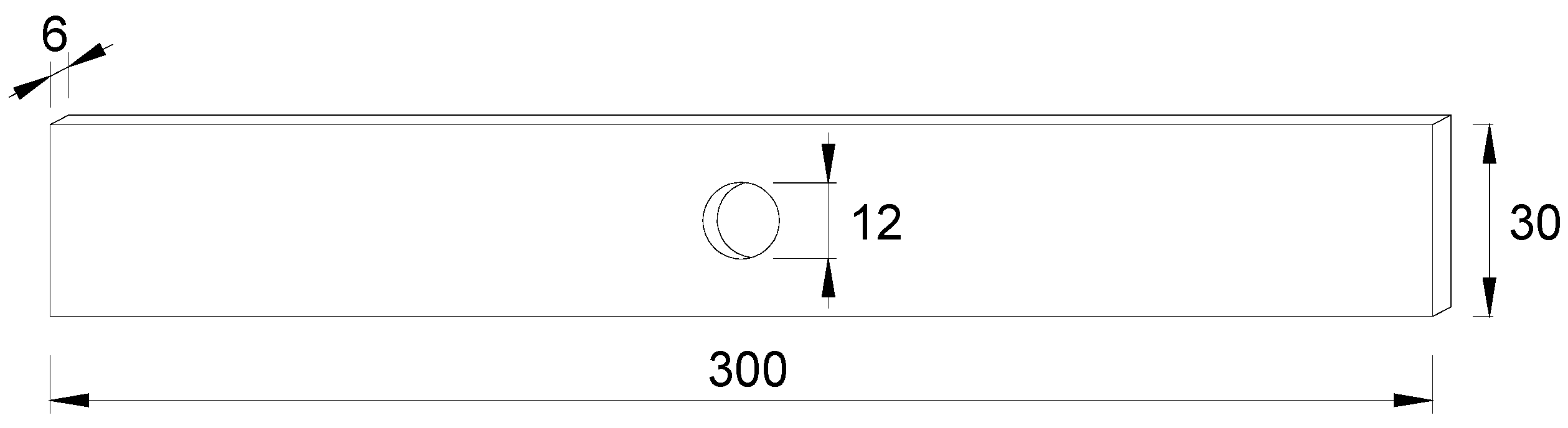
The material used for the test specimens was Grade 345B low alloy steel, in accordance with the Chinese national standard GB/T1591. Related chemical composition and mechanical properties are shown in Table 1. The shape and dimension of the test specimens are shown in Figure 1. In the fabrication, all the test specimens were cut from one steel sheet with accurate geometric dimension control to obtain a final shape of 300 mm × 30 mm × 6 mm. The center hole with the radius of 6 mm was drilled with the use of standard laser cutter. The center of the hole was kept in line with the centerline of the steel plate. In the cutting process, the plate was penetrated as the laser beam moved, melting the materials as it passed. Afterwards, the cut part was blown out with a stream of gas to complete the formation of the hole.
The specimens, which were prepared to be shot blasted, were polished with emery papers of fine particles (i.e., Grit number from 400 to 1600) and then subjected to shot blasting. Related shot blasting conditions are listed in Table 2. The spherical balls used in the shot blasting were alloy steel of a diameter ranging between 0.6 mm and 0.8 mm. The nozzle of the shot blasting device was kept normal to the surface blasted. The shot blasting coverage, which is defined as the proportion of surface area blasted, was taken as 100% with careful examination around the central hole. For the sake of obtaining higher residual compressive stresses, the output of the blasting was chosen as 11 kW in the present study. The blasting time of 2 min was taken on both sides of the plate to obtain a relatively stable shot blasting effect on the basis of many shot blasting trial tests with varying blasting duration. Before and after shot blasting, the surface conditions of the test specimens were determined by roughness measurement using profiled geometry.
A fatigue testing machine, EHF-UV050k2-020-0A, of 50 kN capacity fabricated by Shimadzu Corporation (Kyoto, Japan) was employed. Fatigue testing was performed under load control at a constant stress ratio of 0.1. All tests were conducted at room temperature and humidity. The failure of a test specimen was defined as the rupture of the plate or as when the fatigue crack reached the plate tip, i.e., a crack length of 9 mm. The fatigue life was determined as the corresponding number cycles at the failure of the test specimen. If the test specimen had not failed when the loading cycles surpassed 107, the fatigue test was also terminated. The stress ranges of test specimens were calculated based on the actually measured cross-sectional area.
3. Experimental Results
3.1. Roughness Analysis
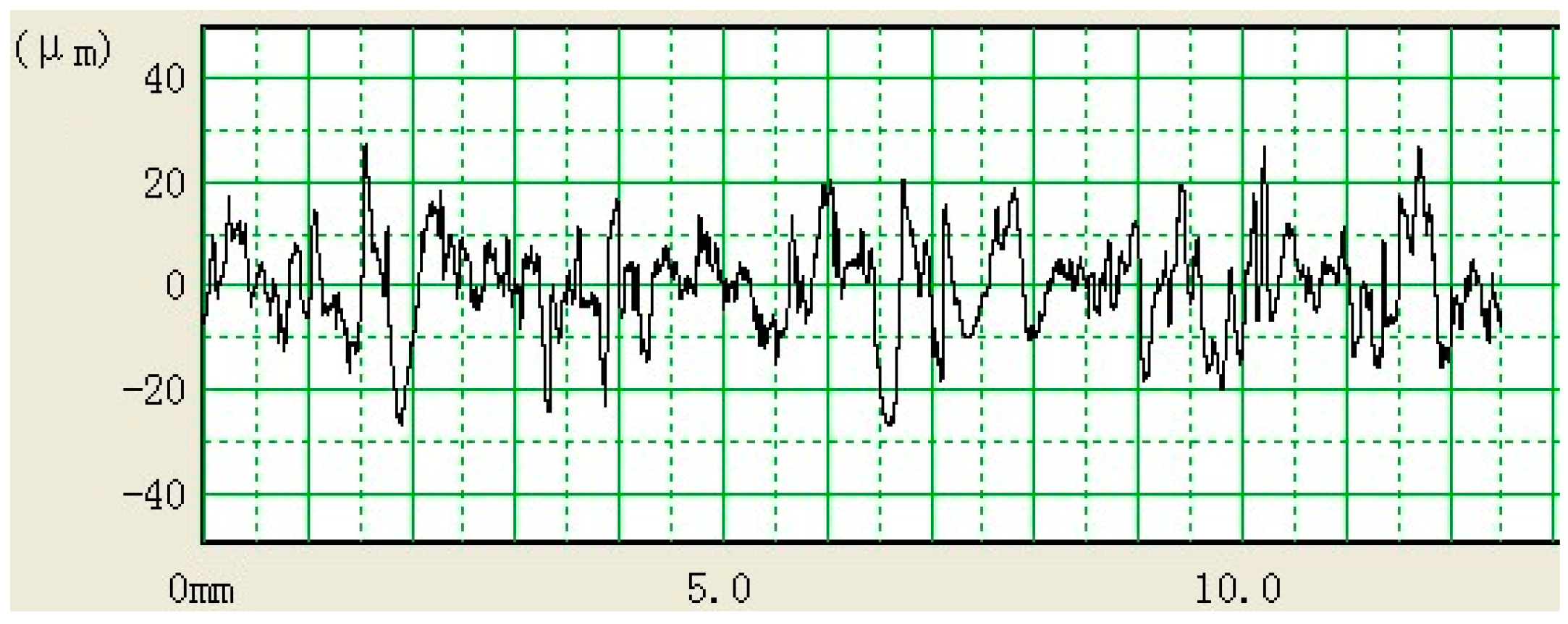
The surface scans of test specimens were made using a Surfcom 5000 surface texture and contour integrated measuring instrument fabricated by Tokyo Seimitsu (Kyoto, Japan). Figure 2 and Table 3 show a typical scan result for the specimen after shot blasting under the vertical and horizontal magnifications of approximately 500 and 10, respectively. The variation of roughness within the measure distance is easily distinguishable, which indicates individual shot impacts on the surface. The listed roughness of test specimens after shot blasting was notably higher than that without shot blasting. This means the difference of surface roughness is greatly reflected as a result of the pre-stressed compressive effect. With the aid of the X-ray diffraction technique, the magnitude of residual compressive stress by shot blasting was determined as 180 MPa to a depth of approximately 0.09 mm from the surface.
3.2. Fractographic Observation
All of the test specimens failed with the fatigue fracture initiated at the edge of the central hole. The fracture surfaces of test specimens were examined by means of a scanning electron microscope (SEM, Hitachi, Ltd., Tokyo, Japan). A typical observation at the stress range of 210 MPa is shown in Figure 3. The crack initiation can be seen at the defect induced by shot blasting on the fracture surface. This defect can be regarded as the critical defect, since its further propagation can lead to first crack initiation. By zooming in on the defect from the magnification of approximately 30 to 400 and 1000, the initial side size of the defect can be approximated as 260–280 μm, which is lower than that for the specimen without shot blasting (350–370 μm). This is expected, as shot blasting brings compressive pre-stress on the surface which in turn condenses the size of the defect.
3.3. Stress Range versus Fatigue Life (S-N) Relation and Comparison
The nominal stress approach has been applied extensively in fatigue design of steel components by most codes. This approach is based on the relation between the stress range, Δσ, and the number of cycles to failure, N, as:
where exponent m is the slope of the S-N relation, and C is the material constant-related parameter [12]. The fatigue design procedure is based on relating the detail with respect to the nominal stress range with a specific category. For comparison, the S-N relation suggested by EN 1993-1-9 [13] is taken into account by assuming slope m = 3 and calculating for a confidential level of 95% probability of survival for log(N). The S-N relation is defined as:
If log(C) has been calculated, the design category can be calculated as:
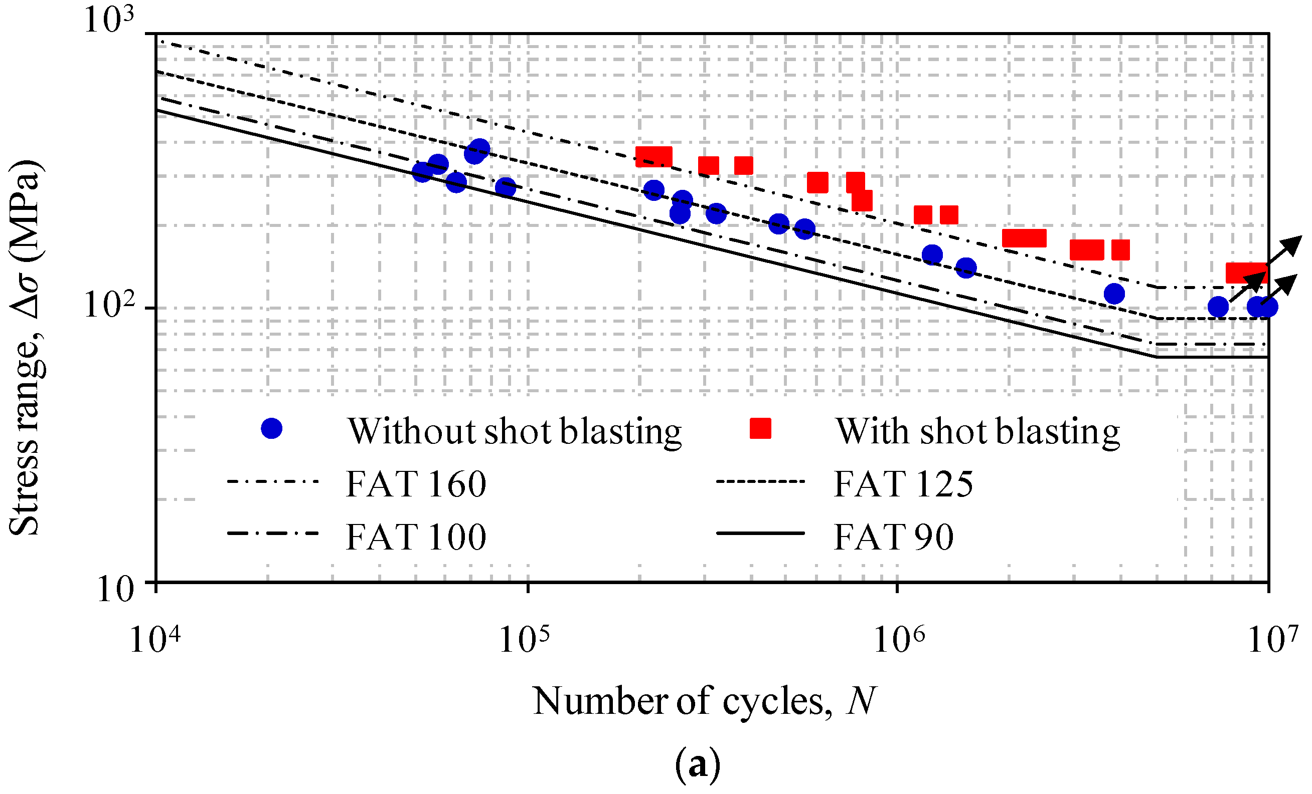
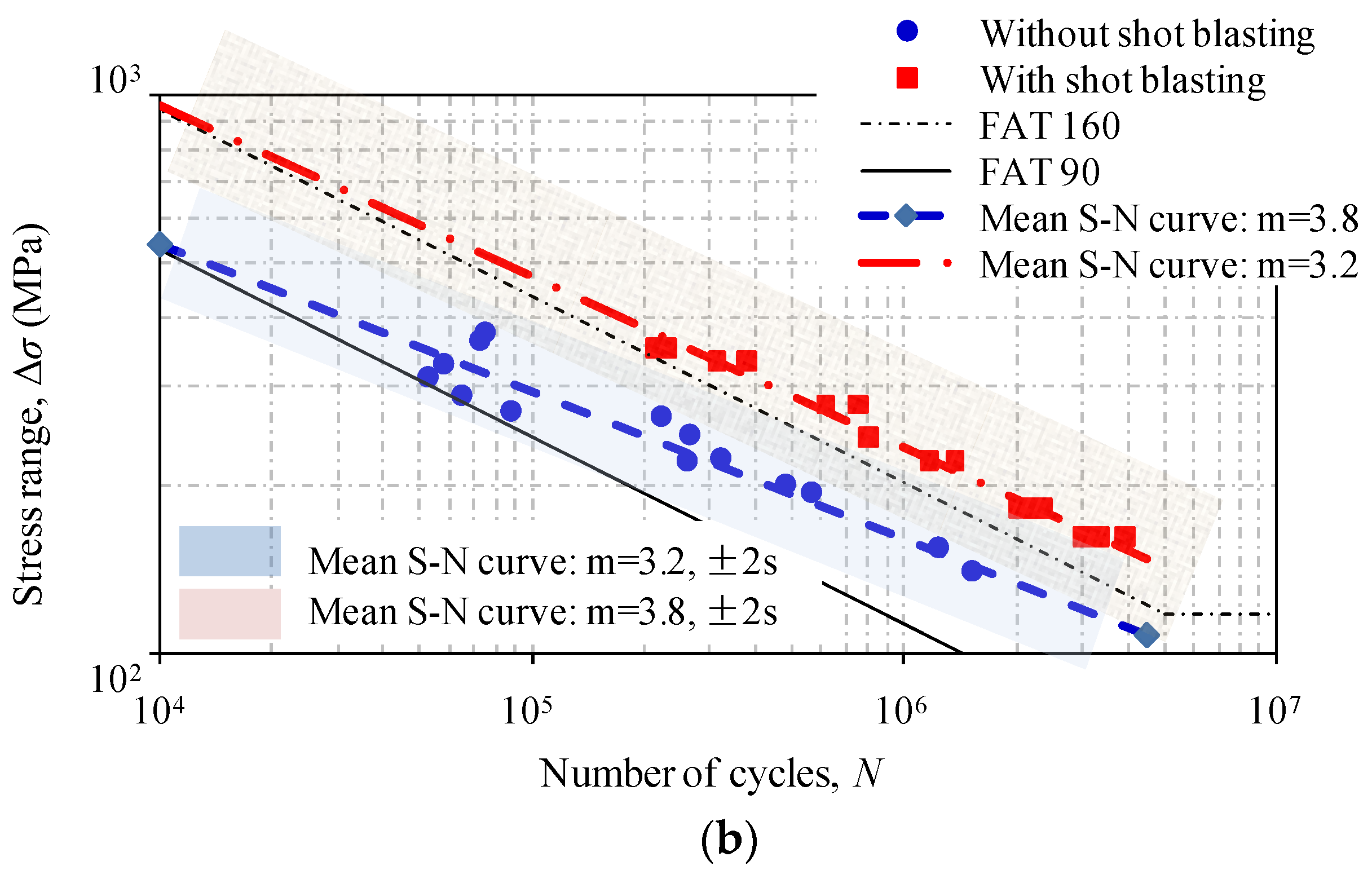
Fatigue test data (FAT) are summarized and plotted on a standard S-N diagram as shown in Figure 4a. Fatigue categories, i.e., FAT 90, FAT 100, FAT 125, and FAT 160, represent the fatigue strengths at 2 million cycles as codified in the EN 1993-1-9 [13]. The arrow denotes that the fatigue failure had not taken place when the tests were terminated at nearly 107 cycles. The test data is fitted by the method of least squares, in which the life results within the fatigue limit are not taken into account in the fitting the parameters. Using free regression analysis, the corresponding S-N relations for test specimens can be expressed as:
- (i)
- For specimens without shot blasting:
- (ii)
- For specimens with shot blasting:
The comparison of test data in Figure 4 shows that the specimen without shot blasting is close to FAT 90, which agrees with the codified suggestion for drilled holes [13]. In contrast, the specimen after shot blasting exhibits a notable increase in the fatigue strength, which can be classified as FAT 160. To better the diagrammatic presentation and comparison, the linearized boundaries method outlined by Reference [14] was introduced, as shown in Figure 4b. It can be seen that a single slope represented by this method can be useful in the correlation with the test data, justifying the necessity of a global and simplified approach.
4. Discussion
The fatigue strength of steel plate with a central hole is significantly influenced by shot blasting when the fracture surface is concerned. As shown in Figure 3, the fatigue crack is prone to initiate from the defect below the plate surface. For the shot-blasted specimens studied herein, the fatigue failure is influenced by both the defect induced by the shot blasting process and stress concentration at the edge of the central hole. In the former case, the fracture surface at the critical defect reported by Gerin et al. [10] is referred and compared with test observation in Figure 5. It can be seen that the initiation of crack at the aforementioned defect location is similar from this comparison. The internal defects that can be regarded as the original defects close to the surface are condensed as a result of the compressive pre-stress induced by shot basting. Moreover, this agrees with the reported observation by Naidu et al. [6] that the initial direction of the crack of the shot-blasted specimen follows a much shallower angle to the surface. This can be regarded as the consequence of the residual compressive stresses existing in the surface, which translates the direction of the principal tensile stress in the surface layers to that normal to the surface. In other words, the shallow angle of the crack propagation results as the multiple fatigue cracks are propagated in the direction perpendicular to the principal stress. Also, striations were clearly identified in the fatigue crack propagation regions.
As shown in Figure 4, the codified category for the central holed specimens without shot blasting can be indicated as FAT 90, which is in agreement with that reported by Garcia et al. [15]. In the EN 1993-1-9 [13], the category FAT 90 is specified for the details of “hole drilled or reamed” for “structural element with holes subject to bending and axial forces”. From the comparison, it is shown that the shot blasting improve the fatigue strength of test specimens by nearly 30%. Such an increase is apparently lower than that reported by Fujimoto et al. [9] in an experimental study of shot-blast spot-welded steel sheets. The fatigue limit of referred specimens [9] was nearly twice that of the non-shot-blasted ones. Such a difference can be attributed to the fatigue crack propagation modes. The fatigue cracks of referred specimens [9] were found from the tip of a defect of the corona bond portion around the nugget, while those of test specimens were shown to have not only occurred at the surface, but also the location related to the stress concentration induced by the presence of the hole. Regarding this, the effect of shot blasting on the improvement of fatigue strength may not be as salient for specimens with inherent local weakening or defects.
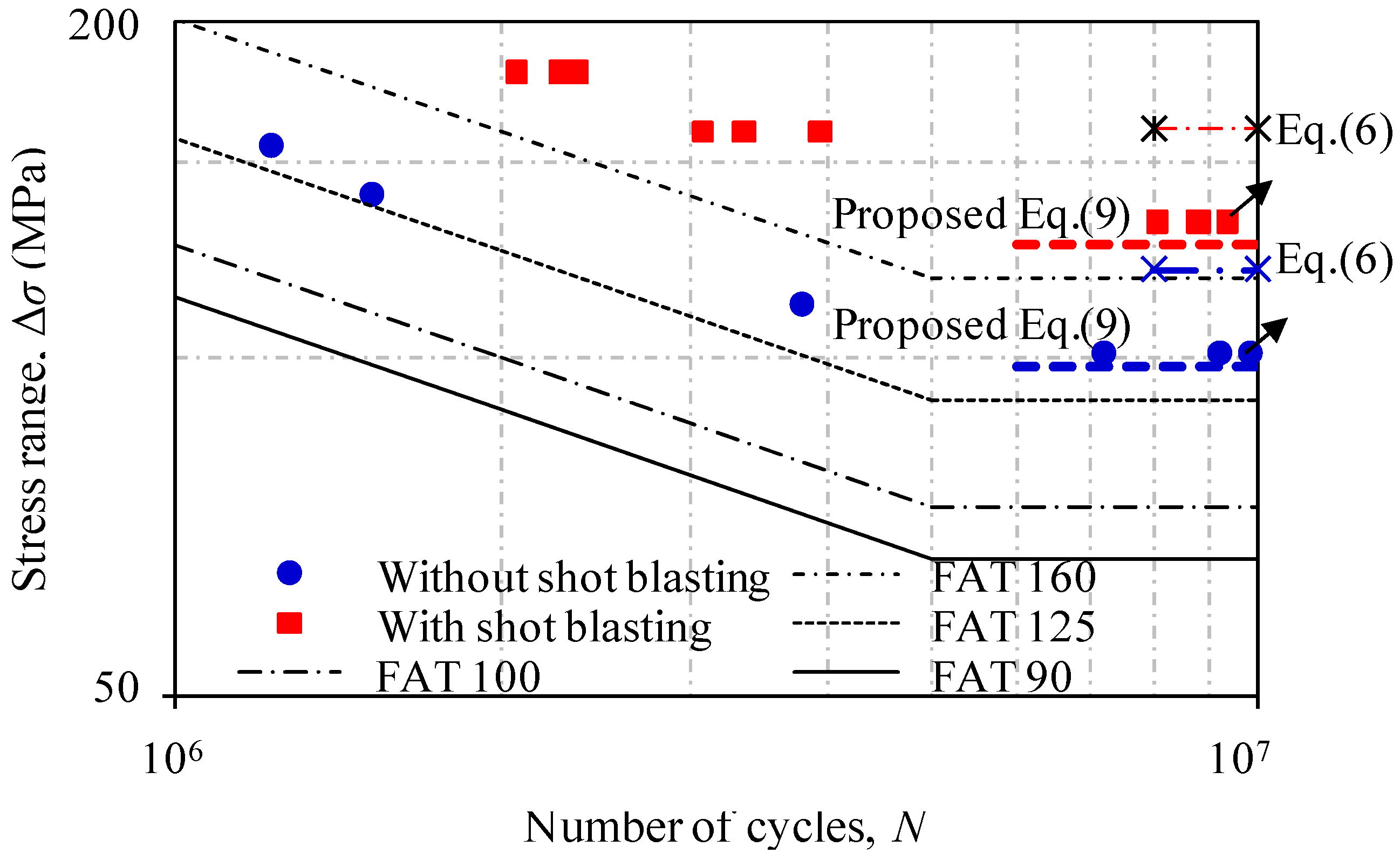
For the purpose of predicting the fatigue strength of the test specimens, the model suggested by Murakami [16] was introduced in this study. In this model, the size of defect and the hardness are considered to be related to the fatigue strength, and then the fatigue limit can be calculated as:
where A = 1.43 for surface defects. de is the size of the defect which is equal to the square root of the defect or notch area. The value of HV is measured hardness, which is given as 109 HV and 161 HV for the specimens without shot blasting and after shot blasting, respectively. The applicability of this model was studied by Gerin et al. [10]. As such, it was used in this study and the calculated results based on Equation (6) are plotted in Figure 6. It seems that the predicted fatigue limits are overestimated for specimens with/without shot blasting, which mirrors the unknown relation to the stress ratio and the local stress concentration induced by the presence of a hole. For the former relation, a correction by adding the stress ratio was considered by Yamabe et al. [11]. For the latter relation, the stress concentration factor (Kto) is herein defined as the ratio of the maximum tensile stress (σ1,max) at the edge of the open hole to the stress that is located far from the hole (σ0). Regarding this, it is assumed that the open hole plate is subjected to a uniform tension magnitude of σ0. Also, the change of the stress distribution in the neighborhood of the hole is expected to be negligible at distances which are large compared with the radius of the hole, i.e., a plate of infinite size. The position of a point can be defined in a polar coordinate by the distance from the center of the open hole (i.e., radius r) and by the angle θ. The tangential stress in polar coordinates [1] can be obtained as:
where rbh is the radius of the central hole. Substituting r = rbh and θ = π/2 or 3π/2 into above equation, the maximum tensile stress at the edge of the open hole can also be calculated to be σ1,max = 3σ0, i.e.,
It is noted that the calculated Kto depending on above assumption of the plate of infinite size is subjected to change, i.e., a plate of finite width or length close to the radius of the hole. Notwithstanding, the stress concentration factor Kto = 3 has been widely adopted for the calculation of stress concentration of open hole details in engineering. As such, it was chosen for the analytical equation herein.
Therefore, the Murakami model can be modified to take into account the relations of the stress ratio as well as the influence of the local stress concentration as:
where the exponent k is given as: k = 0.53 + HV × 10−4. R is the ratio of minimum stress to maximum stress. ms is the surface condition modification factor [17], which depends on the quality of the finish of the actual part surface and on the tensile strength of the part material as:
where σult is the ultimate strength of steel in MPa. For common finishes of the machined parts studied herein, the factor a and exponent b can be given as 4.51 MPa and −0.265, respectively. Moreover, it is worthy of note that the effect of shot blasting has been taken into account in Equation (9) from the aspect of the improvement of the resultant hardness, which was deemed a primary parameter of the fatigue strength by Gerin et al. [11]. The increase of compressive residual stress, on the other hand, is not considered for the sake of simplicity.
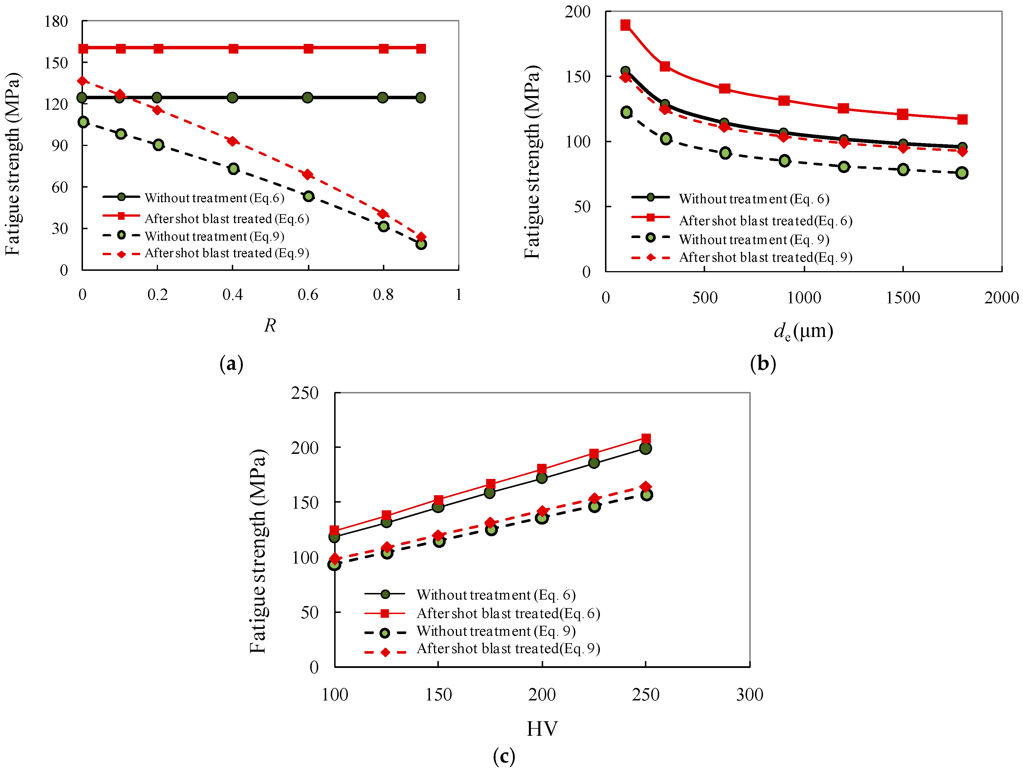
As plotted again in Figure 6, the modified equation exhibited a better correlation with the experimental data of the steel plate with central hole details, whether or not the shot blasting is taken into account. As a further contrast to the original Murakami model, the calculated fatigue strength is plotted in Figure 7 by varying one of the parameters of R, de, and HV while keeping the others unchanged. It is shown that the predicted fatigue strength is least influenced by the hardness, HV, while the descending trend of fatigue strength with the increase of de is similar for the predictions by both models. In comparison, the overestimation of the original Murakami model becomes greater with the increase of stress ratio, R. Moreover, the strength corresponding to the fatigue limit is consistently decreased with the increase of R. Also, the resultant fatigue limit of shot-blasted specimens becomes close to that of specimens without treatment as R is greater than 0.8.
Therefore, the improvement of the modified Murakami model proposed herein for the prediction of fatigue strength is greatly due to the properly allowance of R and de as well as the stress concentration induced by the presence of the hole details. Nevertheless, further experimental and numerical studies are still required to validate this proposed equation.
5. Concluding Remarks
- For shot-blasted specimens, the fatigue failure is influenced by both the defect induced by the shot blasting process and stress concentration at the edge of the central hole. The fatigue cracks are found at the defect below the condensed surface induced by shot blasting. The defect can be regarded as critical since its further propagation can lead to first crack initiation. The shot blasting induces compressive pre-stress on the surface, which in turn condenses the size of the defect. On the other hand, the interaction of stress concentration is not negligible, since it may increase the crack propagation during fatigue loading.
- The codified category for the central holed specimens without shot blasting can be classified as FAT 90 in accordance with EN 1993-1-9. In contrast, shot blasting improves the fatigue category to FAT 160 for the test specimens. However, such an improvement is still lower than that reported by others for the specimens without clear geometric weakening or defects. In this regard, the local stress concentration should be taken into account in the evaluation of the beneficial effect induced by shot blasting.
- The modified Murakami model proposed in this study seems to give a better prediction of the fatigue strength of the central holed specimens with or without shot blasting. The difference between the proposed modification and original model lies in the proper allowance of the stress ratio and the size of the defect as well as the stress concentration induced by the presence of the hole details. These considerations are validated as compared against test results. Nevertheless, more experimental work is still needed to further the understanding of the crack initiation manner of the joint and provide further improvement to proposed method stated herein.
Acknowledgments
The research presented was sponsored by the National Natural Science Foundation of PR China (No. 51308363 and No. 11327801), the Scientific Research Foundation for the Returned Overseas Chinese Scholars (No. 2013-1792-9-4), the Program for Changjiang Scholars & Innovative Research Team in University (No. IRT14R37), and the Science and Technology Support Programs of Sichuan Province (2015GZ0245 and 2015JPT0001).
Author Contributions
Xiang You performed the calculations and wrote the manuscript; Zhiyu Wang conceived the fatigue experiment and supervised the data analysis; Qingyuan Wang chaired technique discussion and supervised students; Mengqin Cao, Mengqin Shen, and Wanqiu Huang assisted in the fatigue experiment and prepared the test samples.
Conflicts of Interest
The authors declare no conflict of interest.
References
- Wang, Z.Y.; Wang, Q.Y.; Li, H.; Zhang, N. Fatigue behaviour of CFRP strengthened open-hole steel plates. Thin-Walled Struct. 2017, 115, 176–187. [Google Scholar] [CrossRef]
- Wang, Z.Y.; Zhang, N.; Wang, Q.Y. Tensile behaviour of open-hole and bolted steel plates reinforced by CFRP strips. Compos. Part B 2016, 100, 101–113. [Google Scholar] [CrossRef]
- Almen, J.O. Shot blasting to increase fatigue resistance. SAE J. 1943, 51, 7248–7268. [Google Scholar]
- Zimmerli, F.P. How shot blasting increases fatigue life. Mach. Des. 1940, 12, 62. [Google Scholar]
- Zimmerli, F.P. Shot blasting and its effect on fatigue life. ASM 1941, 1, 261–278. [Google Scholar]
- Naidu, N.K.R.; Raman, S.G.S. Effect of shot blasting on plain fatigue and fretting fatigue behaviour of Al-Mg-Si alloy AA6061. Int. J. Fatigue 2005, 27, 323–331. [Google Scholar] [CrossRef]
- Gil, F.J.; Planell, J.A.; Padrós, A.; Aparicio, C. The effect of shot blasting and heat treatment on the fatigue behavior of titanium for dental implant applications. Dent. Mater. 2007, 23, 486–491. [Google Scholar]
- Khan, S.A.; Bhuiyanb, M.S.; Miyashitab, Y.; Mutohc, Y.; Koiked, T. Corrosion fatigue behavior of die-cast and shot-blasted AM60 magnesium alloy. Mater. Sci. Eng. A 2011, 528, 1961–1966. [Google Scholar] [CrossRef]
- Fujimoto, H.; Ueda, H.; Ueji, R.; Fujii, H. Improvement of fatigue properties of resistance spot welded joints in high strength steel sheets by shot blast processing. ISIJ Int. 2016, 56, 1276–1284. [Google Scholar] [CrossRef]
- Gerin, B.; Pessarda, E.; Morel, F.; Verdub, C. Influence of surface integrity on the fatigue behaviour of a hot-forged and shot-peened C70 steel component. Mater. Sci. Eng. A 2017, 686, 121–133. [Google Scholar] [CrossRef]
- Yamabe, J.; Kobayashi, M. Effects of surface roughness and residual stress on fatigue strength of shot blasted ductile cast irons with casting surfaces. J. Soc. Mater. Sci. Jpn. 2006, 55, 301–308. [Google Scholar] [CrossRef]
- Suresh, S. Fatigue of Materials, 2nd ed.; Cambridge University Press: Cambridge, NY, USA, 1998; Volume 21. [Google Scholar]
- European Committee for Standardization. Eurocode 3: Design of Steel Structural; Part 1–9; EN 1993-1-9; European Committee for Standardization: Brussels, Belgium, 2005. [Google Scholar]
- Mayorga, L.G.; Sire, S.; Correia, J.A.; De Jesus, A.M.P.; Rebelo, C.; Fernández-Canteli, A.; Ragueneau, M.; Plu, B. Statistical evaluation of fatigue strength of double shear riveted connections and crack growth rates of materials from old bridges. Eng. Fract. Mech. 2017. [Google Scholar] [CrossRef]
- Garcia, T.; Cicero, S.; Alvarez, J.A.; Martín-Meizoso, A.; Bannister, A.; Klimpel, A.; Aldazabal, A. Fatigue performance of thermally cut bolt holes in structural steel S460M. Proc. Eng. 2015, 133, 590–602. [Google Scholar] [CrossRef]
- Murakami, Y.; Endo, M. Effects of hardness and crack geometries on ΔKth of small cracks emanating from small defects. In The Behaviour of Short Fatigue Cracks; Miller, K., De Los Rios, E., Eds.; MEP Publications: London, UK, 1986; pp. 275–293. [Google Scholar]
- Horger, O.J. Metals Engineering Design ASME Handbook, 2nd ed.; McGraw-Hill: New York, NY, USA, 1953. [Google Scholar]
Figure 1.
Dimension specimen (not to scale; all dimensions are in mm).

Figure 2.
Typical surface scan of a test specimen after shot blasting.

Figure 3.
Typical fracture surface for a test specimen (Δσ = 210 MPa).

Figure 4.
Comparison of experimental fatigue data against codified categories: (a) direct comparison with Eurocode 3; (b) statistical analytical results comparison.
Figure 4.
Comparison of experimental fatigue data against codified categories: (a) direct comparison with Eurocode 3; (b) statistical analytical results comparison.


Figure 5.
Comparison of referred and test fracture surface with shot blasting-induced defects: (a) referred image [10]; (b) test SEM image.
Figure 5.
Comparison of referred and test fracture surface with shot blasting-induced defects: (a) referred image [10]; (b) test SEM image.
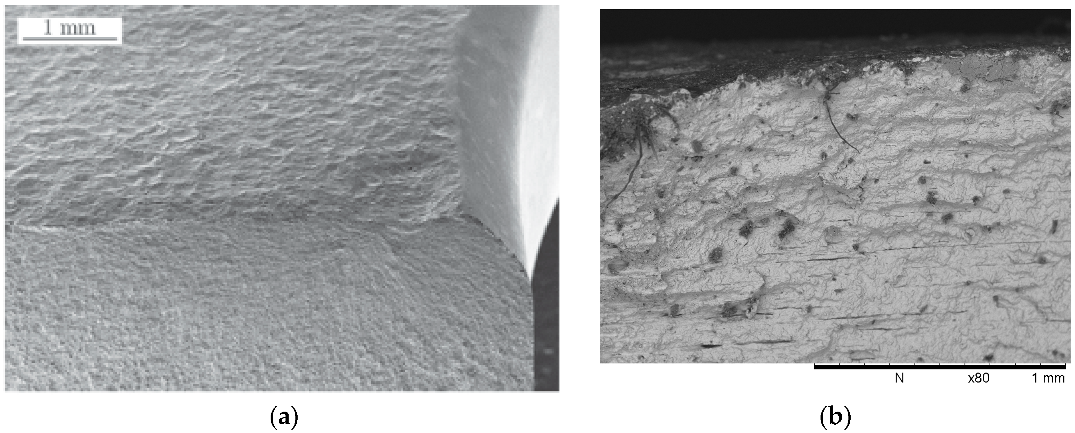
Figure 6.
Comparison of experimental and predicted fatigue limit of test data.

Figure 7.
Comparison of fatigue limit and its theoretically related parameters. (a) Relation with R; (b) Relation with dc; (c) Relation with HV.
Figure 7.
Comparison of fatigue limit and its theoretically related parameters. (a) Relation with R; (b) Relation with dc; (c) Relation with HV.


Table 1.
Chemical composition and mechanical properties of steel at room temperature.
| Steel Grade | Chemical Composition (%) | Mechanical Properties | ||||||
|---|---|---|---|---|---|---|---|---|
| C | Si | Mn | P | S | Yield Strength (MPa) | Ultimate Strength (MPa) | Elongation (%) | |
| Q345B | 0.17 | 0.25 | 1.15 | 0.015 | 0.014 | 388 | 553 | 12 |
Table 2.
Conditions of shot blasting.
| Shot Ball | Projection Velocity | Shot Impact Angle | Arc Height | Output | ||
|---|---|---|---|---|---|---|
| Material | Hardness | Diameter | ||||
| Alloy steel | HRC 40–50 | 0.6–0.8 mm | 90 m/s | 45 | 0.35 mm A | 11 kW |
Table 3.
Comparison of roughness and hardness of test specimens with/without shot blasting.
| Type | Roughness (μm) | Hardness (HV) |
|---|---|---|
| Without shot blasting | 1.07 | 109 |
| With shot blasting | 7.08 | 161 |
Note: Measuring length, 12.5 mm; cut-off length, 2.5 mm.
© 2017 by the authors. Licensee MDPI, Basel, Switzerland. This article is an open access article distributed under the terms and conditions of the Creative Commons Attribution (CC BY) license (http://creativecommons.org/licenses/by/4.0/).
Share and Cite
MDPI and ACS Style
You, X.; Wang, Z.; Wang, Q.; Cao, M.; Shen, M.; Huang, W. Effect of Shot Blasting on Fatigue Strength of Q345B Steel Plate with a Central Hole. Metals 2017, 7, 517. https://doi.org/10.3390/met7120517
AMA Style
You X, Wang Z, Wang Q, Cao M, Shen M, Huang W. Effect of Shot Blasting on Fatigue Strength of Q345B Steel Plate with a Central Hole. Metals. 2017; 7(12):517. https://doi.org/10.3390/met7120517
Chicago/Turabian StyleYou, Xiang, Zhiyu Wang, Qingyuan Wang, Mengqin Cao, Mengqin Shen, and Wanqiu Huang. 2017. "Effect of Shot Blasting on Fatigue Strength of Q345B Steel Plate with a Central Hole" Metals 7, no. 12: 517. https://doi.org/10.3390/met7120517
Note that from the first issue of 2016, this journal uses article numbers instead of page numbers. See further details here.