Thermal Growth Cu1.2Mn1.8O4 Spinel Coatings on Metal Interconnects for Solid Oxide Fuel Cell Applications


School of Materials Science and Engineering, Jiangsu University of Science and Technology, Zhenjiang 212003, China
*
Authors to whom correspondence should be addressed.
Metals 2017, 7(12), 522; https://doi.org/10.3390/met7120522
Submission received: 24 October 2017
/
Revised: 15 November 2017
/
Accepted: 20 November 2017
/
Published: 24 November 2017
Abstract
:A novel cobalt-free Cu1.2Mn1.8O4 spinel coating is prepared and evaluated for the metal interconnect of solid oxide fuel cell. Mn-35Cu and Co-35Mn alloy coatings are deposited on 430 SS substrate and then in-situ oxidized in air at 750 °C for 100 h. XRD results confirm that Cu1.2Mn1.8O4 spinel with some Mn2O3 is formed, and the average thickness of the coating is 70–80 μm according to cross section image. Spinel oxide coating is compact and has good adherence to the substrate, and very low Cr and Fe contents are detected in the coating. A small area specific resistance of 8.7 mΩ cm2 is achieved at 800 °C for the composited Cu1.2Mn1.8O4 spinel coating, which is much less than that of the composited (Co,Mn)3O4 spinel coating. The research indicates that the Cu1.2Mn1.8O4 coating evolved by the high-energy micro-arc alloying process is a promising coating material for the metallic interconnects.
1. Introduction
Ferritic stainless steels are currently the promising most candidate alloys used as metallic interconnects of solid oxide fuel cell (SOFC). Their thermal expansion coefficient (CTE) matches well with the other components of SOFC when operating at an intermediate temperature, between 650 °C and 800 °C. However, a primary problem for ferritic stainless steel’s application is increasing electrical resistance during high temperature operations, which is due to the growth of the Cr-rich surface oxide scale. Furthermore, its application as an interconnector on the cathode side is limited by the volatilization and re-deposition of the Cr oxyhydroxide species on the surface, which causes the rapid performance degradation of the SOFC cathode [1,2].
In order to minimize the electrical resistance of produced oxides and solve the problem of Cr poisoning, some coatings have been developed, such as reactive elements oxide coating [3], rare earth perovskite coating [4,5] and composite spinel oxide coating [6,7], for metallic interconnects. Mn-Co based spinel coatings have been largely studied owing to their high electrical conductivity, excellent chromium retention capability, and thermal matched expansion coefficient with steel substrate. Mn/Co coating [8] was electroplated on the surface of 430 stainless steel. The result showed MnCo2O4 spinel suppressed the growth of the Fe/Cr scale and improved the conductivity of the oxides. While Cu-Mn-based spinel exhibits a close CTE, even higher conductivity, and lower cost than the Mn-Co spinel, it has recently been paid more attention.
Cu1.4Mn1.6O4 spinel oxide [9] was prepared as a cathode for SOFC. The result reveals that polarization resistance is a low value, 0.143 Ω cm2, and the single cell exhibits a high power density at 800 °C. Cu1.3Mn1.7O4 powder coating [10] was prepared by electrophoretic deposition, compacted at 10 ksi, reduced, and then annealed at 850 °C for 100 h. The result led to an outer CuO layer and an inner Cr-rich layer in the interface of the oxides and the substrate. The mixed Cu-Mn oxide coating still has a small area specific resistance (ASR) value at 800 °C. Nickel substituted CuMn2O4 spinel coatings [11] on 430 stainless steel were formed by oxidizing electroplated nickel, copper, and manganese in air at 800 °C. Nickel can accelerate the formation of the Cu-Mn spinel phase and prevent buckling damage of the oxide coatings.
In previous studies, the high-energy micro-arc alloying process (HEMAA) has been proven to be a simple technique to produce a Co-Mn coating at low cost [12,13,14]. The ratio of Co and Mn concentration in the oxide coating is modified by the electrode component and technological parameters that depend on heat consumption per unit area of every electrode. Furthermore, Co-Mn coatings deposited by the HEMAA process all exhibit good adhesion to the ferritic stainless steel substrate during the in-situ thermal oxidation of the coating. This work aims to prepare the Cu-Mn spinel coatings by the HEMAA process. The structure and performance of the Cu-Mn spinel coatings, the evolution of the element concentrations, the electrical conductivity, and the oxygen partial pressure at equilibrium for the Cu-Mn spinel coatings will be investigated at 750 °C in air.
2. Experiments
Type 430 stainless steel is used as substrate with a size of 16 mm × 16 mm × 5 mm. The nominal composition is 16–18 Cr, 1 Mn, 0.12 C, 0.75 Si, 0.03 S, 0.06 Ni, 0.04 P, and balance Fe (all in wt. %). Mn-35Cu alloy (at. %) is smelted by high purity metals (99.99%), which means that the molar ratio of Cu and Mn in the alloy is designed to be about 1.05:1.95. The round rod is cut from Mn-35Cu ingots used as electrodes for the deposition of coating, and its diameter is about 3.2 mm. The strong jet of argon gas is applied to eliminate heating and oxidation when coating is deposited. Deposition parameters [12,13,14] are devised to be on 120 V, 500 Hz, and 1200 W. Co-35Mn alloy and coating is also prepared by the same method for comparison.
Thermal oxidation experiments are conducted at 750 °C in air for 100 h. The samples are suspended in alumina crucibles at first. Before the oxidation commences to run, alumina crucibles with samples are put into constant temperature zone of horizontal tube furnace (Hengli-CHLZG, Luoyang, China). After 100 h, samples are pulled out from the furnace and directly cooled to room temperature (RT).
ASR measurement of Cu-Mn oxide coatings is fulfilled by the four-probe DC method, with applied voltage 5 V and contact area 10 mm2 by Pt paste. The specimens, when measured, are put in horizontal tube furnace in advance. Then, the furnace is heated from room temperature to 500 °C, 600 °C, 700 °C, and 800 °C, successively. Every setting temperature keeps stable for about one hour. ASR value is taken during this process.
Specimens are mounted in a cold-setting epoxy resin for examining the cross-section by scanning electron microscopy (SEM) (JSM-5800, JEOL, Tokyo, Japan). Elemental homogeneity in oxide coatings is determined by energy dispersive X-ray spectroscopy (EDS) (JEOL, Tokyo, Japan). Crystallographic information of Cu-Mn oxide coatings is examined by X-ray diffraction (XRD) analysis (D/MAX-3B, Rigaku Co., Tokyo, Japan).
3. Results and Discussion
3.1. Structure and Morphology of Deposited Coatings
Figure 1 shows composition and morphology of Mn-35Cu alloy and as-deposited coating by HEMAA. All the diffraction peaks of Mn-35Cu coating in Figure 1a are exactly the same as that of Mn-35Cu alloy, which means composition of coating deposited by HEMAA process keeps consistent with that of original alloy electrode. The characteristic peaks of pure Cu and Mn in the standard PDF files are indexed in the XRD patterns. The peaks of Mn-35Cu alloy and coating are different from pure Mn, due to the addition of Cu and possibly, the dopant of Fe and Cr from stainless steel. Mn-35Cu alloy is composed of two phases in Figure 1c. Cu content in the light phase is about 47.18 at. %, higher than 35 at. %. When Mn-35Cu coating is deposited, Cu content is about 33.48 at. %, and a small amount of Fe and Cr element is found on the surface of coating.
Figure 2 shows cross-section morphology of deposited Mn-35Cu and Co-35Mn coating. The continuous and metallurgically bonded coatings can be found in Figure 2a,b, and the interface between coating and substrate is clear. The average thickness of deposited coatings is approximately 50 μm. HEMAA process makes splash appearance and spatters particles on the top surface of coating; it is now operated by hand, so coating thickness sometimes has a very large variation. The diffraction peaks of Co-35Mn coating in Figure 2c are closed to the characteristic peaks of pure Co with a slight left-shift.
3.2. Characteristics of Thermal Growth Coatings
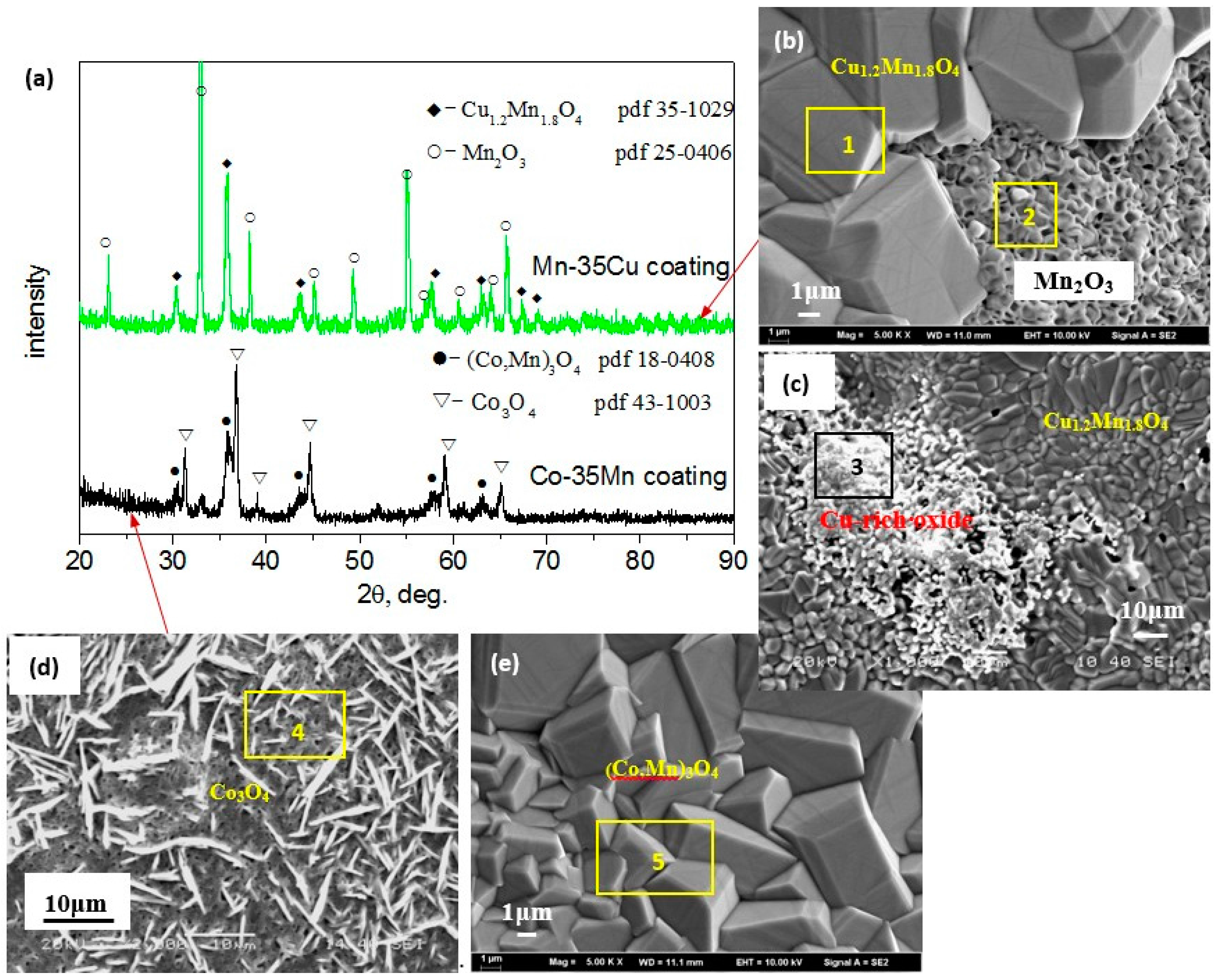
The XRD pattern taken on the oxidized surface of Mn-35Cu and Co-35Mn coatings is showed in Figure 3a. The results disclose that Mn-35Cu coating after exposure to air at 750 °C for 100 h is mainly cubic Cu1.2Mn1.8O4 spinel oxide and Mn2O3 without Fe/Cr oxides. Figure 3b, combined with Table 1, shows that Cu1.2Mn1.8O4 spinel consisted of some large granules. Crystallite size of Mn2O3 in Figure 3b is smaller than Cu-Mn spinel, and some micro-poles uniformly distribute in it. In additional, Cu-rich oxide is found to aggregate in several local regions in Figure 3c, which is a raised and rough oxide. Co-35Mn coating after oxidation at 750 °C for 100 h is mainly (Co,Mn)3O4 spinel, an intermediate tetragonal spinel structure between MnCo2O4 (cubic) and Mn3O4 (tetragonal), with Co3O4 oxide on the surface. Morphology characteristics of (Co,Mn)3O4 and Co3O4 oxide are showed in Figure 3d,e, and have been discussed in previous study [7]. The average grain size of Cu1.2Mn1.8O4 spinel is a little larger than that of (Co,Mn)3O4 spinel. Based on analysis of EDS, the grain size of (Co,Mn)3O4 spinel will accordingly decrease with increasing Mn content in Co-Mn spinel. According to EDS analysis in Table 1, small amount of Fe is detected on the surface of Cu-Mn spinel coating, and molar ratio of element Cu and Mn is near to Cu1.2Mn1.8O4 spinel. Mn content in Co-Mn spinel is higher than MnCo2O4, which is in accordance with XRD in Figure 3.
3.3. Electrical Characterization
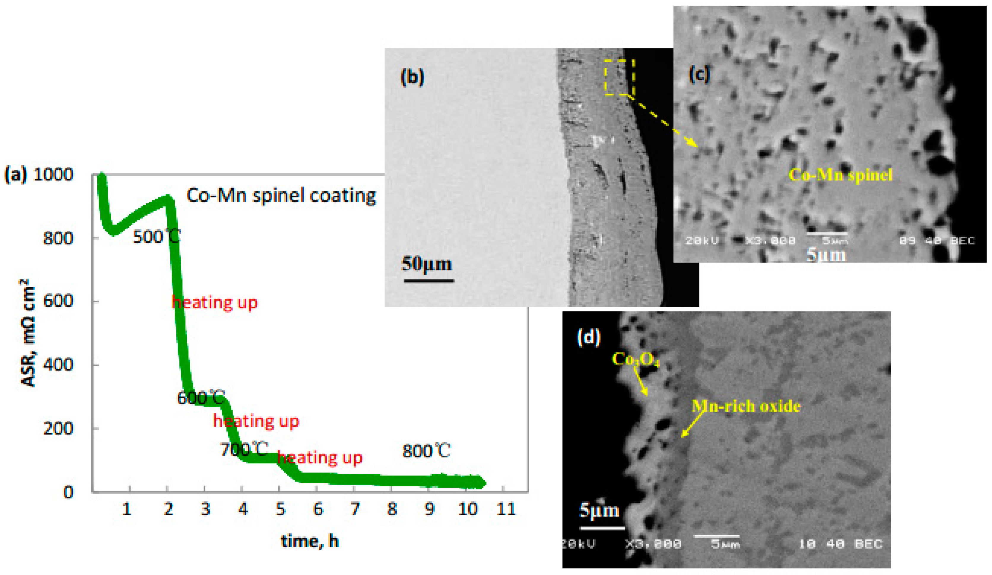
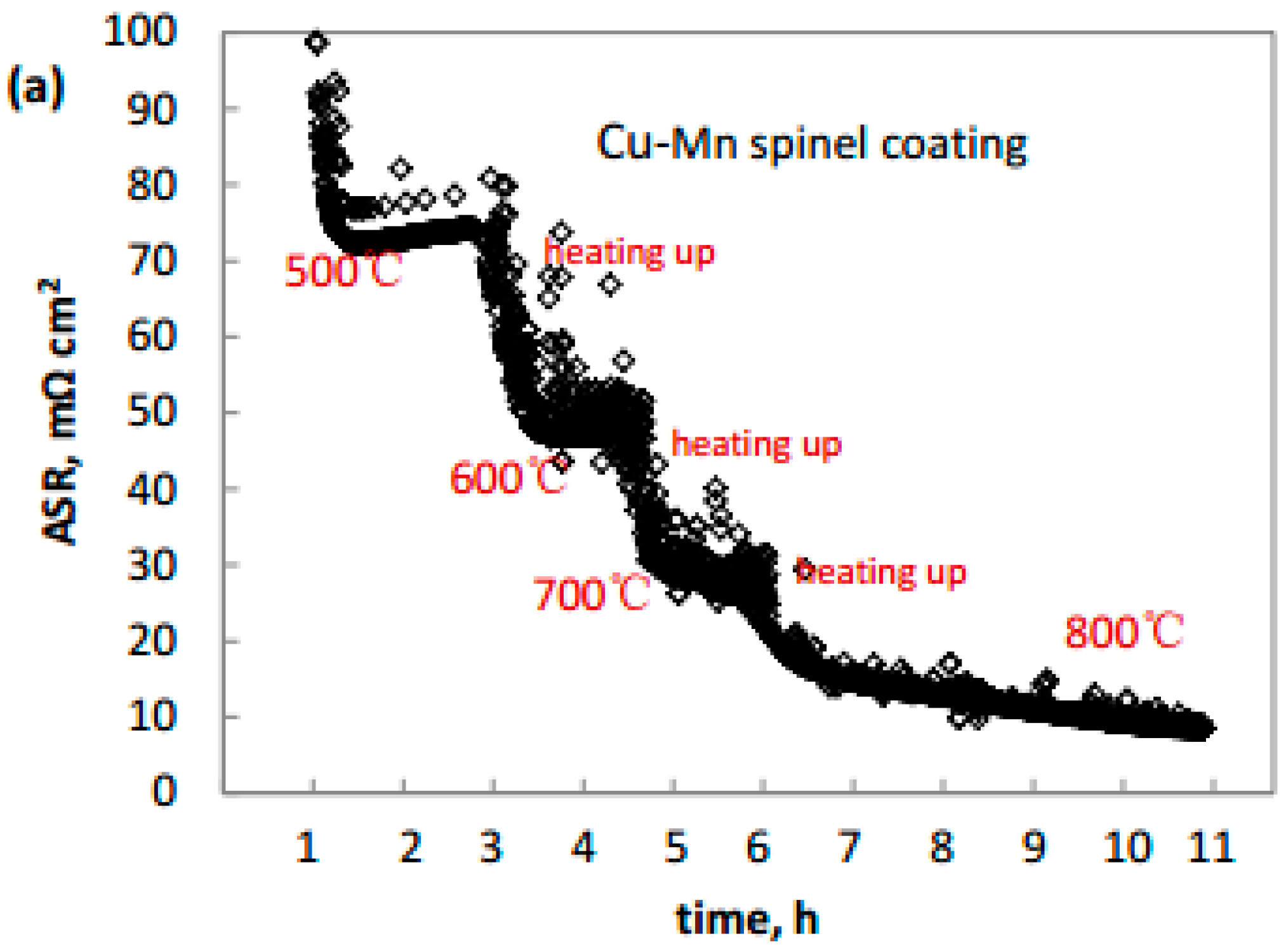
Figure 4 and Figure 5 display ASR and cross-section morphology of Co-Mn and Cu-Mn spinel coatings. The value of ASR in the range of 500–800 °C both decreases with the temperature going up and almost keeps stable with temperature stabilized, except at 500 °C for Co-Mn spinel coating. ASR of Co-Mn spinel coating at 500 °C in Figure 4a is an order of magnitude larger than that of Cu-Mn spinel coating in Figure 5a. When temperature rises up to 600 °C, ASR of Co-Mn spinel coating sharply decreases and is still much larger than that of Cu-Mn spinel. The value of ASR for Co-Mn and Cu-Mn spinel coatings at 800 °C is about 27.2 and 8.7 mΩ cm2, respectively.
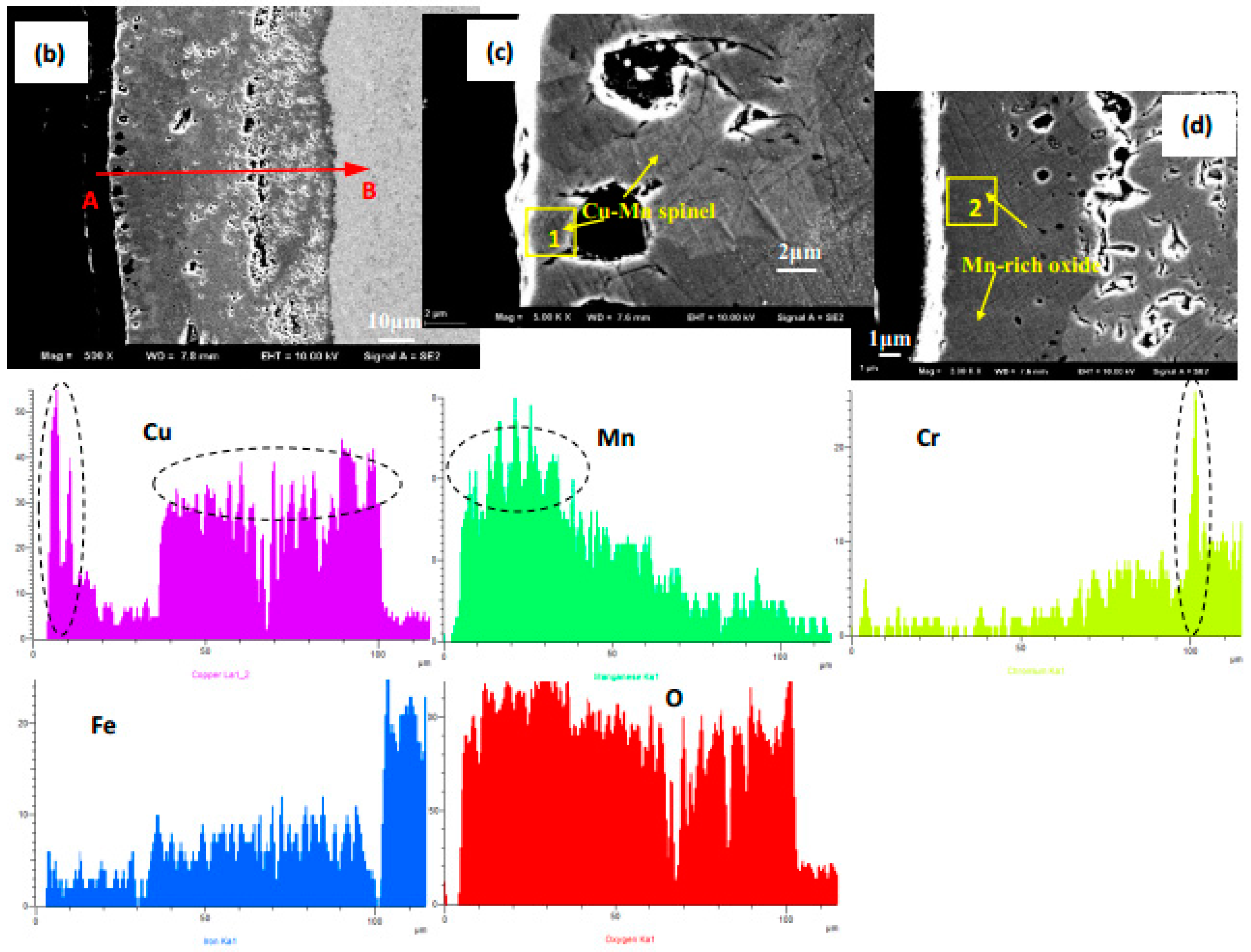
Cross section of Co-Mn spinel coating in Figure 4b–d shows that oxide layer is a little thick and approximately 70–80 μm after oxidation for 100 h. The Co-Mn spinel layer and thin Co3O4 layer on the top surface are also shown. Some fine pores were distributed in external oxides due to surface element diffusion during the oxidation process. Figure 5b shows Cu-Mn spinel coating is uniform, compact, and has excellent adhesion to 430 SS substrate. Some isolated micro-pores are found on the outer part of oxide layer. According to EDS in Table 2, magnification for local areas in Figure 5c,d shows that light phase is composed of Cu-Mn spinel, and dark phase is mainly Mn-rich oxide. The EDS line scan on cross-section of Cu-Mn spinel coating indicates the outermost oxide is rich in Cu and Mn, and then Cu content sharply decreases with Mn content increasing. From the porous middle layer to oxide coating/substrate interface, Mn concentration gradually decreases and Cu concentration almost keeps stable, which is due to fast outward diffusion of Mn. Additionally, Cr content is low in the whole oxide layer, and only a very thin Cr oxide layer formed on the interface. Some Fe from steel substrate diffuses into oxide layer.
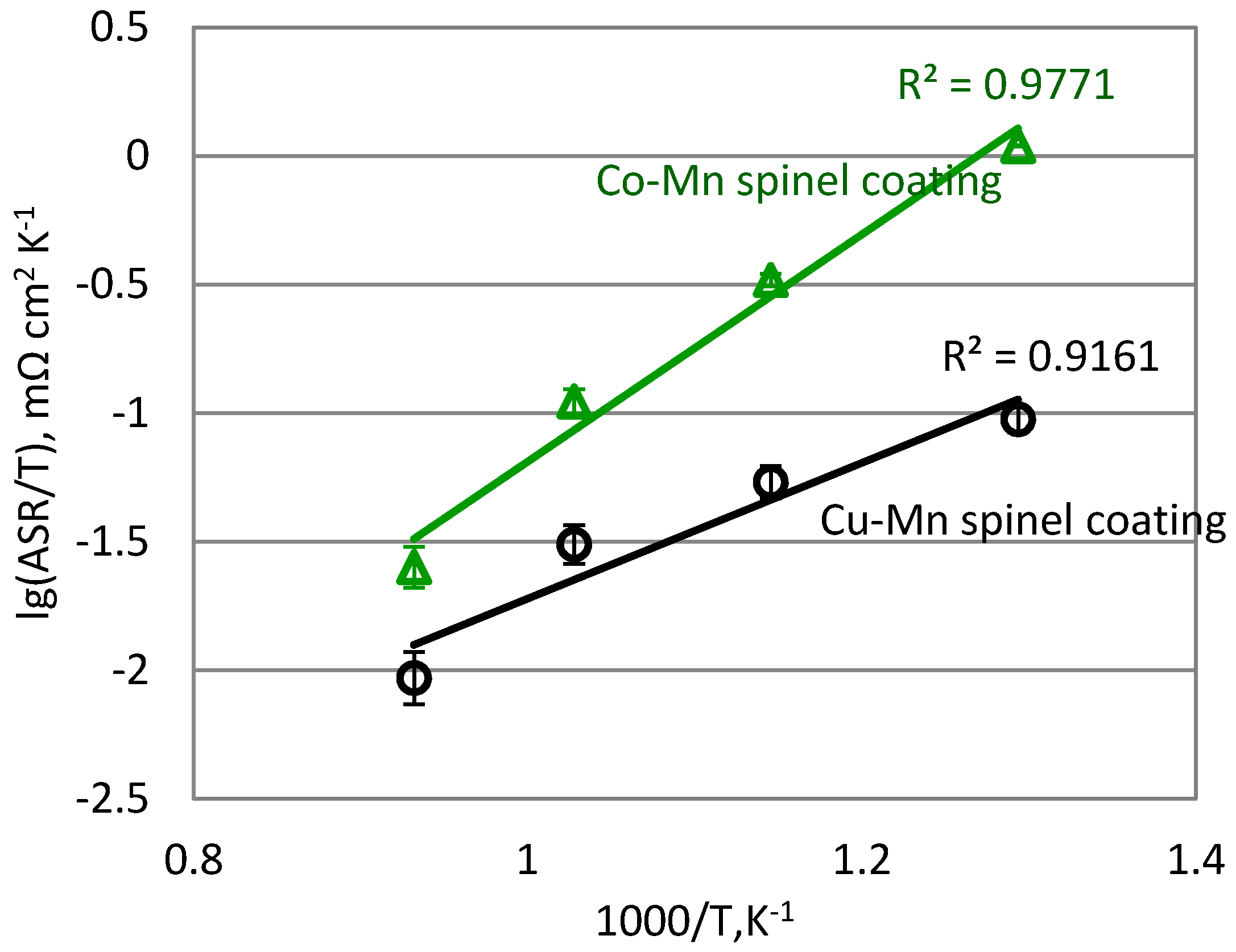
Figure 6 displays Arrhenius plots of ASR/T vs. 103/T for Co-Mn and Cu-Mn spinel coatings. The ASR value decreases linearly between log(ASR/T) and 1/T with increasing temperature, which is related to semiconductor behavior of spinel oxides [15,16]. ASR is directly responsive to the electrical conductivity and thicknesses of thermally grown oxide layers; therefore, Cu-Mn spinel layer exhibits much better electrical conductivity than Co-Mn spinel layer in the range of 500–800 °C.
3.4. Discussion
Only the spinel phase has significant conductivity at high temperatures, so the formation and stabilization of spinel phase in Co-Mn and Cu-Mn coatings need to be strictly controlled. As the above result shows, the non-spinel phase in oxide coatings is mainly Mn2O3, Co3O4, CuO, and Mn3O4, etc.
Partial Cu-Mn-O phase diagram [17] exhibits that it is a very narrow spinel stability region for the CuxMn3−xO4 spinel phase (x = 0.9–1.6), and the value of Ncu for mono-spinel should be less than 1.3 in the operation temperature of intermediate temperature SOFC. Cu-35Mn alloy has a ratio of Cu and Mn 1.05:1.95 in at. %. When Mn-35Cu alloy coating is oxidized at 750 °C, mono-spinel may be produced according to phase diagram. However, the spinel coating is mainly composed of cubic Cu1.2Mn1.8O4 structure, not Cu1.05Mn1.95O4 spinel. The formation of some Mn2O3 indicates a deviation from mono-phase structure.
Previous studies show that composition, concentration, and thickness of alloy coating all affect oxidation products besides oxidation temperature and time [13,18]. Element diffusion at high temperature will lead to element Fe and Cr from 430 SS substrate into oxide coating. The diffusion rate order in composited spinel layer is DMn > DFe > DCr, and the rate of element Cr is one order of magnitude slower than element Mn [19]. The Co-33Cu coating in other work appeared very porous, and Cu enrichment was found because of the pronounced mobility of element Cu [20], which indicates the diffusion rate of Cu is large in Co-Cu spinel coatings. Line scan of cross-section in Figure 5 discloses Cu, Mn is rich in the outmost oxide layer, and some Cu oxides aggregate on several areas in Figure 3, which indicates both Cu and Mn rapid diffusion in Cu-Mn spinel coating. According to calculated partial pressure of oxygen [21] in Table 3, Co3O4 and CuO both favor forms on the surface with high oxygen partial pressure, which explains thin Co3O4 and CuO-rich layer formed on top surface of Co-Mn and Cu-Mn coatings, respectively.
4. Conclusions
A metallurgical bonding Mn-35Cu coating is successfully prepared using the high-energy micro-arc alloying process. Cubic Cu1.2Mn1.8O4 spinel coating, with an area-specific resistance of 8.7 mΩ cm2 at 800 °C, is observed after oxidation at 750 °C for 100 h. A trace amount of Fe and Cr diffusion from 430 SS into the spinel coating occurs during thermal oxidation. The diffusion rate of the Cu and Mn elements is rapid in Cu-Mn oxide layer. Mn2O3 is mainly in the non-spinel phase in the Cu-Mn spinel coating, and all non-spinel phases are dispersed in both oxide coatings. The composited Cu-Mn spinel coating exhibits much higher electrical conductivity than the composited Co-Mn spinel coating, especially at a low temperature. The results demonstrate that Cu1.2Mn1.8O4 could be a promising material for coating metallic interconnects in the intermediate temperature SOFC.
Acknowledgments
This work was financially supported by National Natural Science Foundation of China (51201073), China Scholarship Fund (2017), research fund of Jiangsu University of Science and Technology (1624821607-5), Postgraduate Research & Practice Innovation Program of Jiangsu Province (KYCX17_1830), and the Priority Academic Program Development of Jiangsu Higher Education Institutions.
Author Contributions
Pingyi Guo and Yong Shao conceived and designed the experiments; Yongbiao Lai and Yu Zhang performed the experiments; Pingyi Guo Yuxin Wang and Yong Shao analyzed the data; Yong Shao contributed reagents/materials/analysis tools; Pingyi Guo and Yong Shao wrote the paper.
Conflicts of Interest
The founding sponsors had no role in the design of the study; in the collection, analyses, or interpretation of data; in the writing of the manuscript, and in the decision to publish the results.
References
- Windisch, H.F.; Sattari, M.; Svensson, J.E.; Froitzheim, J. Chromium vaporization from mechanically deformed pre-coated interconnects in solid oxide fuel cells. J. Power Sources 2015, 297, 217–223. [Google Scholar] [CrossRef]
- Stanislowski, M.; Froitzheim, J.; Niewolak, L.; Quadakkers, W.J.; Hilpert, K.; Markus, T.; Singheiser, L. Reduction of chromium vaporization from SOFC interconnectors by highly effective coatings. J. Power Sources 2007, 164, 578–589. [Google Scholar] [CrossRef]
- Magrasó, A.; Windisch, H.F.; Froitzheim, J.; Svensson, J.E.; Haugsrud, R. Reduced long term electrical resistance in Ce/Co coated ferritic stainless steel for solid oxide fuel cell metallic interconnects. Int. J. Hydrogen Energy 2015, 40, 8579–8585. [Google Scholar] [CrossRef]
- Feng, Z.J.; Xu, Y.X.; Zeng, C.L. Preparation and high temperature performances of DyCrO3-based coatings on a ferritic stainless steel interconnect material. J. Power Sources 2013, 235, 54–61. [Google Scholar] [CrossRef]
- Yang, X.L.; Tu, H.Y.; Yu, Q.C. Fabrication of Co3O4 and La0.6Sr0.4CoO3-δCe0.8Gd0.2O2-δ dual layer coatings on SUS430 steel by in-situ phase formation for solid oxide fuel cell interconnects. Int. J. Hydrogen Energy 2015, 40, 607–614. [Google Scholar] [CrossRef]
- Zhu, J.H.; Lewis, M.J.; Du, S.W.; Li, Y.T. CeO2-doped (Co,Mn)3O4 coatings for protecting solid oxide fuel cell interconnect alloys. Thin Solid Films 2015, 596, 179–184. [Google Scholar] [CrossRef]
- Lai, Y.B.; Guo, P.Y.; Shao, Y.; Zhang, Y.; Liu, N. The Role of Dy Doping on Oxidation Behavior of Co-40Mn/Co Coating for Solid Oxide Fuel Cell Metal Interconnects. J. Alloys Compd. 2017, 694, 383–393. [Google Scholar] [CrossRef]
- Wu, J.W.; Johnson, C.D.; Gemmen, R.S.; Liu, X.B. The performance of solid oxide fuel cells with Mn-Co electroplated interconnect as cathode current collector. J. Power Sources 2009, 189, 1106–1113. [Google Scholar] [CrossRef]
- Zhen, S.Y.; Sun, W.; Li, P.Q.; Tang, G.Z.; Rooney, D.; Sun, K.N.; Ma, X.X. High performance cobalt-free Cu1.4Mn1.6O4 spinel oxide as an intermediate temperature solid oxide fuel cell cathode. J. Power Sources 2016, 315, 140–144. [Google Scholar] [CrossRef]
- Sun, Z.H.; Gopalan, S.; Pal, U.B.; Basu, S.N. Cu1.3Mn1.7O4 spinel coatings deposited by electrophoretic deposition on Crofer 22 APU substrates for solid oxide fuel cell applications. Surf. Coat. Technol. 2017, 323, 49–57. [Google Scholar] [CrossRef]
- Joshi, S.; Petric, A. Nickel substituted CuMn2O4 spinel coatings for solid oxide fuel cell interconnects. Int. J. Hydrogen Energy 2017, 42, 5584–5589. [Google Scholar] [CrossRef]
- Guo, P.Y.; Shao, Y.; Zeng, C.L.; Wu, M.F.; Li, W.L. Oxidation characterization of FeAl coated 316 stainless steel interconnects by high-energy micro-arc alloying technique for SOFC. Mater. Lett. 2011, 65, 3180–3183. [Google Scholar] [CrossRef]
- Zhang, Y.; Guo, P.Y.; Shao, Y.; Lai, Y.B.; Zhang, J.Q. Preparation and high-temperature performance of Co-10Mn and Co-40Mn alloy coatings for solid oxide fuel cell metal interconnects. J. Alloys Compd. 2016, 680, 685–693. [Google Scholar] [CrossRef]
- Lai, Y.B.; Guo, P.Y.; Shao, Y.; Tang, P.J.; Zhang, Y.; Zhang, J.F. Formation and performances of spinel reaction layers on Co-40Mn coatings under an oxygen pressure of 105 Pa for solid oxide fuel cell interconnect application. Vacuum 2016, 130, 14–24. [Google Scholar] [CrossRef]
- Zhou, W.; Xu, X.F.; Ouyang, C.; Wu, J.; Gao, Y.Q.; Huang, Z. Annealing effect on the structural, electrical and 1/f noise roperties of Mn-Co-Ni-O thin films. J. Mater. Sci. Mater. Electron. 2014, 25, 1959–1964. [Google Scholar] [CrossRef]
- Yokoyama, T.; Meguro, T.; Kato, K.; Okazaki, S.; Ito, D.; Tatami, J.; Wakihara, T.; Kome, K. Preparation and electrical properties of sintered oxide composed of MnFeNiO4 with a cubic spinel structure. J. Electroceram. 2013, 31, 353–359. [Google Scholar] [CrossRef]
- Bateni, M.R.; Wei, P.; Deng, X.H.; Petric, A. Spinel coatings for UNS 430 stainless steel interconnects. Surf. Coat. Technol. 2007, 201, 4677–4684. [Google Scholar] [CrossRef]
- Zhang, H.; Wu, J.W.; Liu, X.; Baker, A. Studies on elements diffusion of Mn/Co coated ferritic stainless steel for solid oxide fuel cell interconnects application. Int. J. Hydrogen Energy 2013, 38, 5075–5083. [Google Scholar] [CrossRef]
- Tian, Z.Y.; Bahlawane, N.; Vannier, V.; Hoinghaus, K.K. Structure sensitivity of propene oxidation over Co-Mn spinels. Proc. Combust. Inst. 2013, 34, 2261–2268. [Google Scholar] [CrossRef]
- Fu, Q.X.; Tietz, F.; Sebold, D.; Wessel, E.; Buchkremer, H.P. Magnetron-sputtered cobalt-based protective coatings on ferritic steels for solid oxide fuel cell interconnect applications. Corros. Sci. 2012, 54, 68–76. [Google Scholar] [CrossRef]
- Young, D.J. High Temperature Oxidation and Corrosion of Metals, 1st ed.; Elsevier Ltd.: Cambridge, UK, 2008; pp. 29–47. ISBN 978-0-08-044587-8. [Google Scholar]
Figure 1.
X-ray diffraction (XRD) (a) and scanning electron microscopy (SEM) morphology of Mn-35Cu alloy and Mn-35Cu coating on 430 SS by high-energy micro-arc alloying process (HEMAA); (b) Mn-35Cu coating, (c) Mn-35Cu alloy.
Figure 1.
X-ray diffraction (XRD) (a) and scanning electron microscopy (SEM) morphology of Mn-35Cu alloy and Mn-35Cu coating on 430 SS by high-energy micro-arc alloying process (HEMAA); (b) Mn-35Cu coating, (c) Mn-35Cu alloy.
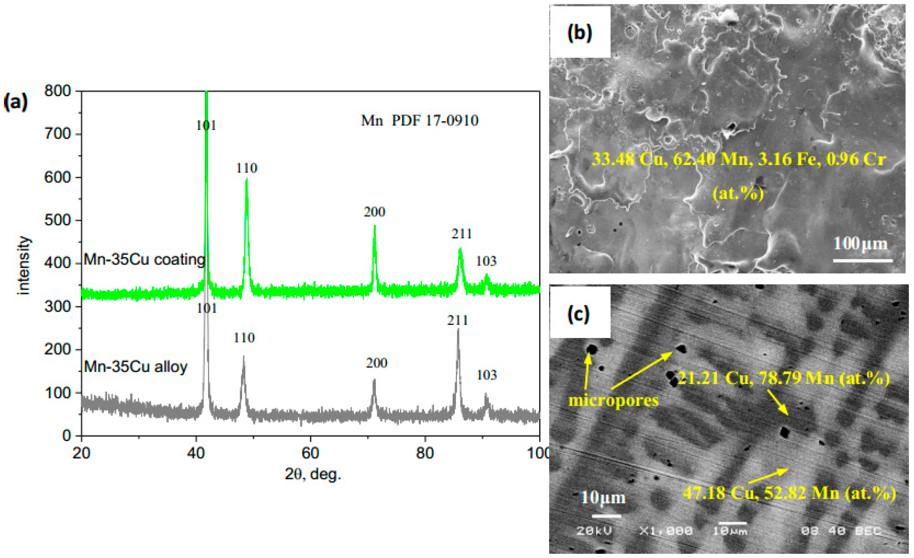
Figure 2.
(a) Cross-section morphology of Mn-35Cu coating deposited by HEMAA; (b) cross section of Co-35Mn coating deposited by HEMAA; and (c) X-ray diffraction of Co-35Mn coatings.
Figure 2.
(a) Cross-section morphology of Mn-35Cu coating deposited by HEMAA; (b) cross section of Co-35Mn coating deposited by HEMAA; and (c) X-ray diffraction of Co-35Mn coatings.
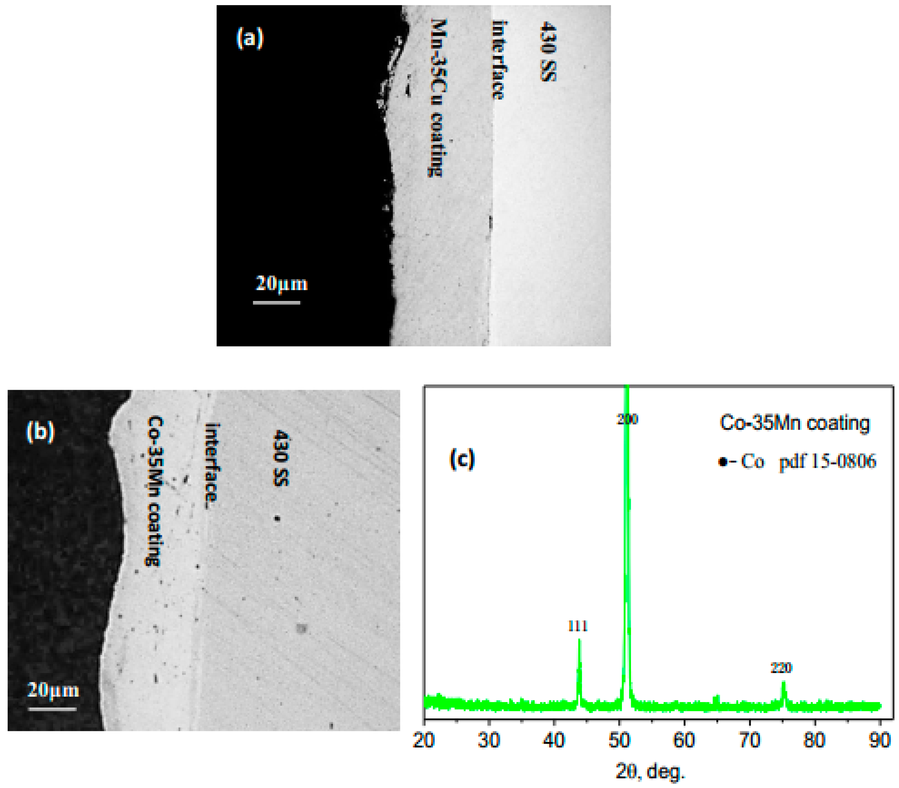
Figure 3.
(a) X-ray diffraction of Mn-35Cu and Co-35Mn coatings oxidized at 750 °C in air for 100 h; (b,c) surface morphology of Mn-35Cu coating oxidized at 750 °C in air for 100 h; (d,e) surface morphology of Co-35Mn coating oxidized at 750 °C in air for 100 h.
Figure 3.
(a) X-ray diffraction of Mn-35Cu and Co-35Mn coatings oxidized at 750 °C in air for 100 h; (b,c) surface morphology of Mn-35Cu coating oxidized at 750 °C in air for 100 h; (d,e) surface morphology of Co-35Mn coating oxidized at 750 °C in air for 100 h.

Figure 4.
(a) Area specific resistance (ASR) of Co-Mn spinel coating with a temperature range of 500–800 °C; (b) cross-section morphology of Co-Mn spinel coating; (c) a section with Co-Mn spinel scale; and (d) a section with Co3O4 oxide.
Figure 4.
(a) Area specific resistance (ASR) of Co-Mn spinel coating with a temperature range of 500–800 °C; (b) cross-section morphology of Co-Mn spinel coating; (c) a section with Co-Mn spinel scale; and (d) a section with Co3O4 oxide.

Figure 5.
(a) ASR of Cu-Mn spinel coating with a temperature range of 500–800 °C; (b) cross-section morphology of Cu-Mn spinel coating and the line scan position shown in the image; (c) a section with Cu-Mn spinel scale; (d) a section with Mn-rich scale.
Figure 5.
(a) ASR of Cu-Mn spinel coating with a temperature range of 500–800 °C; (b) cross-section morphology of Cu-Mn spinel coating and the line scan position shown in the image; (c) a section with Cu-Mn spinel scale; (d) a section with Mn-rich scale.


Figure 6.
Arrhenius plots of ASR/T vs. 103/T for Co-Mn and Cu-Mn spinel coatings.


Table 1.
Composition analysis of local areas in Figure 3 by energy dispersive X-ray spectroscopy (EDS).
Table 1.
Composition analysis of local areas in Figure 3 by energy dispersive X-ray spectroscopy (EDS).
| Elements, at. % | Co | Mn | Cu | Fe | Cr | O | Notes |
|---|---|---|---|---|---|---|---|
| Mn-35Cu coating, 100 h | - | 25.67 | 14.30 | 1.36 | - | 58.67 | area 1 |
| - | 30.67 | 1.78 | 1.29 | - | 66.26 | area 2 | |
| - | 7.97 | 37.19 | 0.54 | - | 54.30 | area 3 | |
| Co-35Mn coating, 100 h | 36.54 | 5.32 | - | - | - | 58.15 | area 4 |
| 15.23 | 21.96 | - | - | - | 62.80 | area 5 |
Table 2.
Composition analysis of local areas in Figure 4 by EDS.
Table 2.
Composition analysis of local areas in Figure 4 by EDS.
| Elements, at. % | Co | Mn | Cu | Fe | Cr | O | Notes |
|---|---|---|---|---|---|---|---|
| Mn-35Cu coating, 100 h | - | 21.13 | 20.02 | - | - | 58.85 | area 1 |
| - | 32.70 | 2.83 | 4.92 | - | 59.55 | area 2 |
Table 3.
Standard free energies (ΔGo) of reactions and oxygen partial pressure (PO2) at equilibrium at 750 °C. ΔGo values for the mole numbers are shown in the chemical equations.
Table 3.
Standard free energies (ΔGo) of reactions and oxygen partial pressure (PO2) at equilibrium at 750 °C. ΔGo values for the mole numbers are shown in the chemical equations.
| Number | Reaction | T, °C | ΔGo, J mol−1 | PO2, atm |
|---|---|---|---|---|
| 1 | Mn(s) + 1/2O2(g) = MnO(s) | 750 | −337,829.6 | 3.15 × 10⁻³⁵ |
| 2 | 2/3Cr(s) + 1/2O2(g) = 1/3Cr2O3(s) | 750 | −285,442.0 | 7.07 × 10⁻³⁰ |
| 3 | 3Mn(s) + 2O2(g) = Mn3O4(s) | 750 | −259,818.1 | 2.92 × 10⁻²⁷ |
| 4 | Fe(s) + 1/2O2(g) = FeO(s) | 750 | −197,985.8 | 6.03 × 10⁻²¹ |
| 5 | 3FeO(s) + 1/2O2(g) = Fe3O4(s) | 750 | −184,232.7 | 1.53 × 10⁻¹⁹ |
| 6 | Co(s) + 1/2O2(g) = CoO(s) | 750 | −161,559.9 | 3.16 × 10⁻¹⁷ |
| 7 | Cu(s) + 1/2O2(g) = CuO(s) | 750 | −64,946.9 | 2.32 × 10⁻⁷ |
| 8 | 3CoO(s) + 1/2O2(g) = Co3O4(s) | 750 | −31753.7 | 5.71 × 10⁻⁴ |
© 2017 by the authors. Licensee MDPI, Basel, Switzerland. This article is an open access article distributed under the terms and conditions of the Creative Commons Attribution (CC BY) license (http://creativecommons.org/licenses/by/4.0/).
Share and Cite
MDPI and ACS Style
Guo, P.; Lai, Y.; Shao, Y.; Zhang, Y.; Wang, Y. Thermal Growth Cu1.2Mn1.8O4 Spinel Coatings on Metal Interconnects for Solid Oxide Fuel Cell Applications. Metals 2017, 7, 522. https://doi.org/10.3390/met7120522
AMA Style
Guo P, Lai Y, Shao Y, Zhang Y, Wang Y. Thermal Growth Cu1.2Mn1.8O4 Spinel Coatings on Metal Interconnects for Solid Oxide Fuel Cell Applications. Metals. 2017; 7(12):522. https://doi.org/10.3390/met7120522
Chicago/Turabian StyleGuo, Pingyi, Yongbiao Lai, Yong Shao, Yu Zhang, and Yuxin Wang. 2017. "Thermal Growth Cu1.2Mn1.8O4 Spinel Coatings on Metal Interconnects for Solid Oxide Fuel Cell Applications" Metals 7, no. 12: 522. https://doi.org/10.3390/met7120522
Note that from the first issue of 2016, this journal uses article numbers instead of page numbers. See further details here.