Effect of Different Welding Processes on Electrochemical and Corrosion Behavior of Pure Nickel in 1 M NaCl Solution

1
State Key Laboratory of Advanced Processing and Recycling of Non-ferrous Metals, Lanzhou University of Technology, Lanzhou 730050, China
2
State Key Laboratory of Nickel and Cobalt Resources Comprehensive Utilization, Jinchang 737100, China
*
Author to whom correspondence should be addressed.
Metals 2017, 7(12), 532; https://doi.org/10.3390/met7120532
Submission received: 28 September 2017
/
Revised: 19 November 2017
/
Accepted: 27 November 2017
/
Published: 29 November 2017
Abstract
:A plasma arc welding (PAW)-tungsten inert gas (TIG) hybrid welding process is proposed to weld pure nickel. In PAW-TIG welding, the arc of the PAW was first to be ignited, then TIG was ignited, while in PAW welding, only the PAW arc was launched. This paper investigated the effect of different welding processes on electrochemical and corrosion performance of between a pure nickel joint and a base metal in an aerated 1 M NaCl solution, respectively. The average grain size of the joint fabricated by PAW welding (denoted as JP joint) is 463.57 μm, the joint fabricated by PAW-TIG welding(denoted as JP-T joint) is 547.32 μm, and the base metal (BM) is 47.32 μm. In this work, the passivity behaviors of samples were characterized for two welding processes by electrochemical impedance spectroscopy (EIS), open circuit potential versus immersion time (OCP-t), and the potentiodynamic polarization plots. EIS spectra, attained with different immersion times, were analyzed and fitted by an equivalent electrical circuit. Photomicrographs of BM, JP, and JP-T were also taken with a scanning electron microscope (SEM) to reveal the morphological structure of the pit surfaces. Electrochemical tests show that the sequence of the corrosion resistance is BM > JP > JP-T. The size and quantity of the hemispherical corrosion pits of all samples are different. The corrosion morphology observations found a consistency with the consequence of the electrochemical measurements. The results show that an increase of the grain dimensions due to different heat treatments decreased the pure nickel stability to pitting corrosion.
1. Introduction
Nickel and its alloys have received considerable attention among metallic metals because of their matchless properties, such as sound corrosion resistance, excellent temperature resistance, and specific strength performance, which can be extensively explored for technological and structural applications [1,2]. Generally speaking, the properties of nickel and its alloys are inevitably connected with the welding process, resulting in the microstructure and specific performances of the welded metal being significantly distinguished from that of the base metal. However, welding of nickel and its alloys has continuously attracted attention by industrial productions because of their potential benefits; for example, saving cost, reducing design risk, and enhancing product functionality. Thus, the corrosion behaviors of the welded joints obtained by different welding methods are definitely different from the base metal. Proper welding method should result in joints with corrosion properties meeting particular demands and sound corrosion resistance of welds is indispensable to scale up the engineering application in advanced manufacturing industries.
Corrosion behaviors of pure nickel have been continually studied in different corrosion media. Manoj studied the hot corrosion of nickel in a NaOH melt and it was seen that the formation of sodium nickelate (NaNiO2), obtained by the dissolution of nickel element and the surface coating of nickel oxide were found on the nickel surface, resulting in a notably high corrosion rate [3]. Benoît investigated, comparatively, the electrochemical properties of passive films grown on pure nickel under two conditions, within chloride ions and without chloride ions, by electrochemical impedance spectroscopy (EIS) and the Mott-Schottky measurements [4]. Barbosa also studied not only the chloride ions, which participated in the dissolution process on nickel electrodes in an acid electrolyte, but also the formation of the surface layer and the induction of pitting, and pointed out that the role of Cl− in affecting the formation of the passive layer of the nickel surface via reactions of intermediates [5].
Furthermore, Meng indicated that a nanocrystalline nickel coating would improve the corrosion resistance owing to the formation of a uniform film [6,7]. Li investigated the electrochemical corrosion behavior of a Ni-based nanocrystalline coating versus different grain sizes in a NaCl acidic solution, and pointed out that the smaller coating grain size could enhance the performance of a compact film with high pitting corrosion resistance [8]. There have studies that indicate that the corrosion resistances of passive metals or alloys were remarkably enhanced with the refining of the grains [9,10].
Despite there being considerable numbers of studies on the passivity of nickel and its alloys, there are still some problems that need to be solved. One of the problems is the corrosion behavior of weldments, obtained via different welding methods, on the role of different immersion times, on the properties of the passive layer. It is speculated that different welding processing and service environments have an ineluctable effect on the surface film and, thus, on the corrosion performance. Therefore, the aims of this work are concerned with different welding processes for different electrochemical characteristics of joints and the base metal in aerated 1 M NaCl solution with different immersion times at room temperature.
2. Experimental Procedures
2.1. Material
The base metal (BM) used in this study was pure nickel N6 with dimensions of 150 mm × 60 mm × 3.5 mm. Table 1 shows the chemical composition of the BM.
2.2. Welding Procedure
In this work, plates of N6 were autogenously butt-jointed without groove preparation and filler by a plasma arc welding (PAW)-tungsten inert gas (TIG) hybrid welding process, in which the axis of the two torches are arranged in a straight line with perpendicular to the welding direction and the PAW torch is installed in front of TIG with the distance between two torches being 75 mm and plasma arc welding (PAW). Prior to welding the sheets, edges were ground with 600 # sand paper and were thoroughly cleaned chemically by acetone in order to avoid any source of contamination, which could result in weld defects. For a concise description in this paper, the joint fabricated by PAW welding is denoted as the JP joint, while the joint by PAW-TIG welding is denoted as the JP-T joint. It is worth emphasizing here that the best welding parameters available in the fabrication industry were used by a large amount of experimental exploration. No preheat and post-heat treatment was carried out on the specimens, and the two welding parameters performed in this experiment were mentioned in Table 2.
2.3. Electrochemical Testing
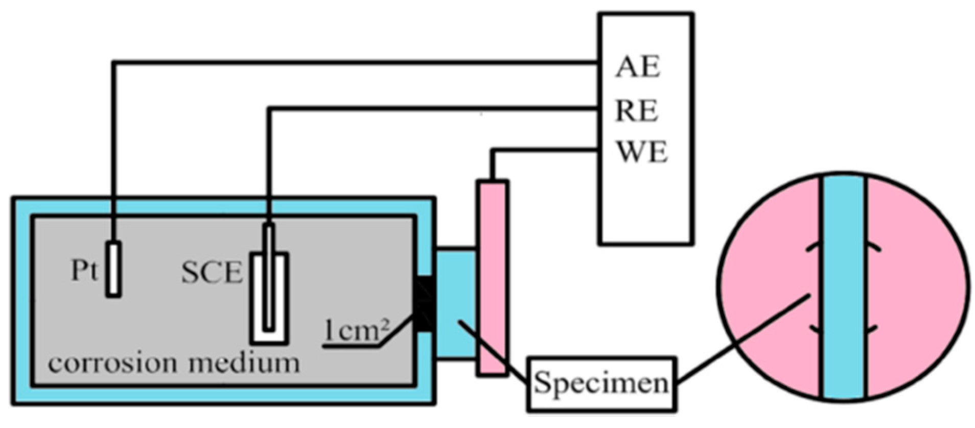
For electrochemical studies, samples of the BM, JP, and JP-T were cut with an exposed area of 4 cm2. Before electrochemical measurements, all samples were abraded by SiC paper in a series of grades up to 2000 #, and then mechanically polished with diamond polishing powder to ensure homogenized surfaces. All specimens were degreased in alcohol, cleaned in deionized water, and dried thoroughly with a hair drier. Electrochemical measurements were respectively carried out with an electrochemical workstation (CHI660E, Chenhua, Shanghai, China) in aerated 1 M NaCl solution at room temperature. Electrochemical tests were performed using a standard three-electrode system and the schematic diagram of the corrosion testing setup used for the present study is shown in Figure 1. The samples were used as the working electrodes (WE), with the circular working area of 1 cm2 exposed to the solution, while a saturated calomel electrode (ESCE = +0.244 V) and a Pt sheet were used as the reference electrode (RE) and auxiliary electrode (AE), respectively. In order to ensure the reality and reproducibility of the experiment processes, experiments for each sample were conducted at least three times and the averaged result was taken.
At the beginning of each test, the WE was first performed for cathodic polarization at −0.650 V for 30 min to remove the native oxides because it has been proved that the real reflections of electrochemical measurement performed on the passive film would be improved after cathodic polarization [4,11,12,13,14].
The test specimens were then set in 1 M NaCl solution for up to 72 h to obtain relatively steady values of the open circuit potential with time (OCP-t) after cathodic pretreatment. The objective of measuring OCP-t was to explain the degradation initiation of the metal surface according to changes of potential at different exposure times. For potentiodynamic polarization curves, the samples were excited −1 V towards the anodic direction with a scanning rate of 1 mV/s. In this way, the metal surface can be activated first, and then the surface of the metal changes from activation to passivation with the increase of the potential.
Electrochemical impedance spectroscopy (EIS) measurements were carried out at the OCP after the specimens had been immersed for 1, 6, 12, 24, 48, and 72 h, respectively. The testing frequency ranges from 100 kHz to 10 mHz with an applied AC disturbance signal of 10 mV rms (root mean square). The EIS spectra were interpreted based on equivalent electrical circuits and further fitted by ZSimpWin 3.21 software (Echem Software, Ann Arbor, MI, USA, 2014) using a nonlinear least squares (NLLS) fitting program.
3. Results and Discussion
3.1. Microstructures
Figure 2 shows the microstructures of the BM, JP, and JP-T. An aqueous solution of CH3COOH:HNO3:H2O (2:2:1) was used for etching the specimens with the etching time being 12–15 s. From Figure 2a, it can be seen that the equiaxed and homogeneous austenitic structure, with an average grain size of 47.32 μm measured by IMAGE-PRO-PLUS (Media Cybernetics, Rockville, MD, USA), was taken on. From Figure 2b,c, JP and JP-T are composed of single-austenite structures. However, different austenite sizes could be observed in the two welds. It is observed that as heat input increases, the grain size in the weld also increases. As shown in the weld metal of JP, the coarse austenite-cellular structure has an average grain size of 463.57 μm, in which there are some dendrite cells in the interior of each large crystal. By comparison, the JP-T is composed of a coarse austenite-columnar structure with the average grain size of 547.32 μm, which is due to the increase of total heat input by the extra TIG arc. It is well known that different welding methods cause the corrosion resistance of welded metal to be different.
3.2. Open Circuit Potential
The measurement of OCP-t is used to study the stability and corrosion changes of the surface layer. Figure 3 shows the OCP-t of the BM, JP, and JP-T in aerated 1 M NaCl solution for immersion over a period of 72 h. The time profiles of OCP-t obtained for three samples are quite similar. Initially, OCP values change quickly towards more positive potentials during the 6 h after cathodic polarization pretreatment, which indicates a spontaneous passivation of BM, JP, and JP-T because of the formation of an oxide film in NaCl solution open to the air. After that, all specimens in the solution were gradually passivated until the OCP finally reached relatively constant values at 30 h. The outstanding shift of the OCP values of all three samples shows the self-passivation when the corrosion process is dominated by the passivation effect. The self-passivation of pure nickel and nickel alloy C-22 in chloride solutions has been reported by several researchers [15,16,17]. It was observed that the corrosion potential firstly increased toward the positive direction and then reached constant values after a very long period of time. It was suggested that the primary action of water molecules on the sample surface, as compared with the role of aggressive chloride ions, resulted in the ennoblement of the OCP value.
From the presented OCP-t curves it is concluded that the BM exhibits a much more positive value compared to the joints in the initial stage. This may be attributed to the granular and inter-granular actions on the local electronic properties of the passive film grown on nickel single-crystal surfaces [18]. However, the difference in OCP values between the JP and JP-T samples decreased to only about 8 mV. On the basis of the above discussion, it is reasonable to note that it is very difficult to correlate the cause for OCP ennoblement of the JP specimens as compared with the JP-T to the influencing factor, namely, significant microstructure change. The stability and the resistance of the passive film of sample surface in aerated 1 M NaCl solution with different soaking times will be discussed in the EIS section.
3.3. Polarization Measurements
Potentiodynamic polarization plots of BM, JP, and JP-T in aerated 1 M NaCl solution are displayed in Figure 4. Polarization curves can give many significant aspects on electrochemical corrosive behaviors of the samples. Electrochemical data, such as zero current potential (EZCP), corrosion current density (icorr), cathodic Tafel slope (βc), passive current density (ipass), and critical pitting potential (Epit) were developed from the measured curves. The current density of cathodic curves should be ascribed to the reduction reaction of the soluble oxygen ions that is controlling not only he electron transfer, but also by diffusion in 1 M NaCl solution open to the air [19]. Epit was determined as the potential at which the current density increases significantly, and rather rapidly, above the ipass. In all cases, the βc measurement started at least 60 mV away from EZCP and the linear region at least 120 mV was used. The anodic Tafel branches shown in Figure 4 do not show a well-defined experimental Tafel trend due to the anodic curves showing an active to passive transition. According to Figure 4, three samples show the same trend with different Tafel parameters. The corresponding electrochemical parameters calculated from the measured cathodic curves are listed in Table 3.
The results show a significant influence of different welding processes on corrosion behavior of pure nickel, where the anodic and cathodic currents are compensated due to different signs around the corrosion potential. For these joints the EZCP decreases with the values shifting in the cathodic direction. There was, generally, a progressive shift in EZCP towards the noble direction for BM compared to joints. However the corrosion current densities of the joints were increased compared to the BM with an augmentation of icorr by 10 times for joint specimens. There was a noticeable change in the ipass for BM compared to joints. BM exhibited higher ipass compared to coarse-grained JP and JP-T. This indicates the defective nature of the passive film that forms on BM. It has been suggested that this should allow for easier Ni cation diffusion through a more defective film, thereby leading to higher ipass [20]. The lower tendency for localized grain boundary corrosion in nanocrystalline nickel has also been earlier observed [21]. For JP and JP-T, there is evidence of a significant decrease in the critical pitting potential compared to the BM. The JP and JP-T specimens exhibited a small cathodic shift of Epit, i.e., −29 mV and −141 mV, respectively, compared to the BM. There was also a systematic increase in EZCP and ipass with an increase in grain size, while the Epit showed the opposite trend. It was in agreement with Mishra that nanocrystalline nickel of different grain sizes (8–28 nm) exhibited active-passive potentiodynamic polarization behavior [22]. The formation of a passive film is one of the main properties of pure nickel. However, the microstructure heterogeneity during weld metal solidification may significantly alter the stability of the formation of the film and then corrosion behaviors of the joints. The properties of the passive film seem deteriorated as well from the welding process, resulting in an augmentation of ipass from 2.16 µA/cm2 (BM) to 6.48 µA/cm2 (JP) and to 7.35 µA/cm2 (JP-T), respectively. The imperfect passivation associated with joints may also be related to intrinsic electrochemical behavior associated with the disordered intercrystalline region in nickel. Thus, it can be concluded that JP has a relatively good corrosion resistance compared with JP-T, but these joints are lower than BM.
3.4. Electrochemical Impedance Spectroscopy
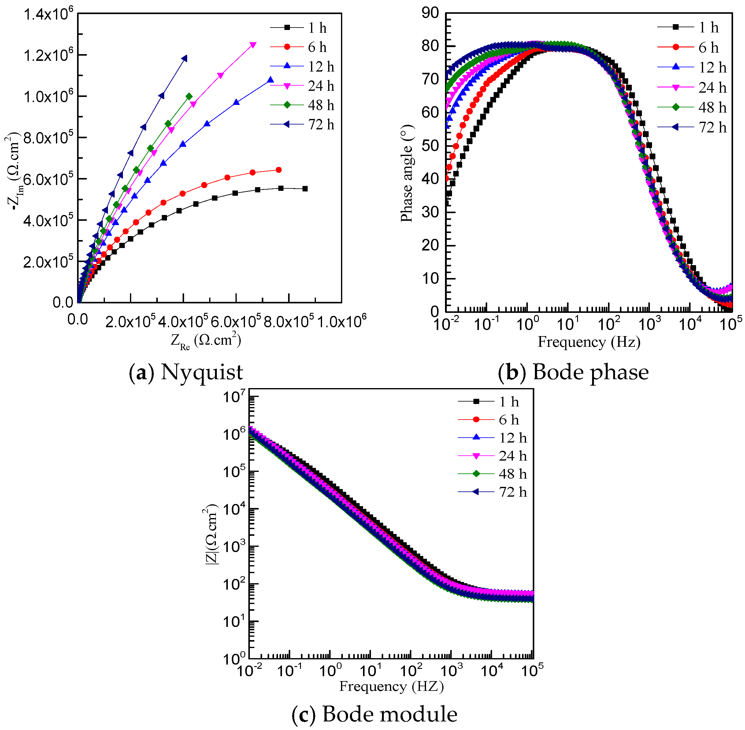
Generally, for further determining the electrochemical characteristics of passive films formed on BM, JP, and JP-T, EIS measurements were carried out around OCP value after soaking in 1 M NaCl solution at room temperature with different times for 1, 6, 12, 24, 48, and 72 h. The results are presented in the format of Nyquist and Bode plots versus immersion times for the BM, JP, and JP-T, respectively, as shown in Figure 5, Figure 6 and Figure 7.
For all specimens at different immersion times, the Nyquist plots (Figure 5a, Figure 6a, and Figure 7a) show a common feature, occurrence of the incomplete semi-circle reveals the active charge transfer between the metal and NaCl solution [23]. The Bode phase angle plots (Figure 5b, Figure 6b and Figure 7b) exhibit an inflection in the medium frequency range of 1 kHz–0.1 Hz, attributed to the response of double layer capacitance. The number of distinguishable peaks or hollows is a representation of the relaxation process (time constant) appearing in the electrochemical system of EIS [24].Thus, the one time constant is well defined for three samples through the Bode diagram at medium frequency. It is clearly presented that the augmentation of the phase angle with an increase in the immersion time, as shown in Figure 5, Figure 6 and Figure 7. The maxima of the phase angle of all Bode phase plots, covering a wide range of frequencies, suggest the formation of a stable passive film. Accompanying the immersion time, the impedance diagrams are very similar, which means that the passive films become relatively stable. Passive films grown for all samples have a similar evolution, that is, the charge transfer resistance increases with the soaking time. Thus, the charge transfer resistance for passive film grown is globally higher for JP than that for JP-T, but all those values are slightly lower than BM.
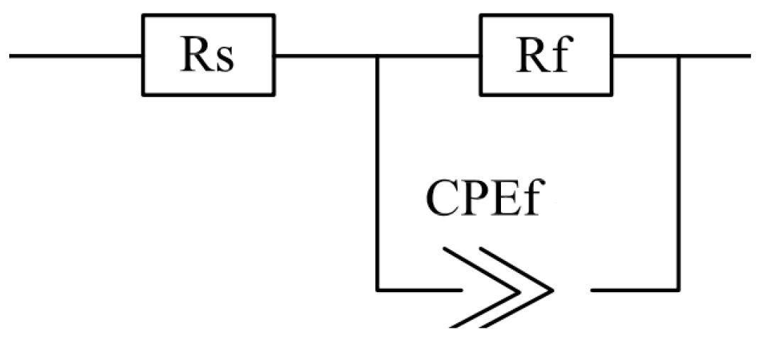
It has been demonstrated that the passive films of pure nickel can be more accurately described as a double layer structure, consisting of an inner defective oxide layer and an outer hydroxide layer formed from the reaction of metal cations with species in the solution [4,25]. The medium-low frequency time constant is concerned with the defective oxide barrier layer. The equivalent electrical circuit (EEC), used to analyze the EIS spectra displaying one time constant for the passive film, is illustrated in Figure 8. In this model, Rs corresponds to the resistance of the solution.
Normally, the constant phase element (CPE) is added to replace the capacitance owing to the surface of samples being non-homogeneous, which represents a non-ideal capacitance behavior of the electrode/solution interface or, more specifically, in the case of the oxide film, to the distribution of resistivity accompanying the thickness of the passive films [26,27,28,29]. The value of CPE is related with the depression of the Nyquist semicircle and it is associated with the condition and the surface properties of the film. The mathematical formulation of the impedance of the CPE is shown as follows:
where j2 = −1, ω is the angular frequency, and n is an empirical index with the value between 0 and 1 [4].
ZCPE(ω) = [Q(jω)n]−1
The validity of the above model is confirmed based on the better non-linear least square fitting of the experimental data within a 5% error. The fitted impedance parameters obtained for three specimens are summarized in Table 4. For three samples, after 12 h immersion n values are relatively similar and are independent of the immersion time, while the Qf fluctuates with increasing immersion time, which indicates the continuous modification of the films. It is seen that the value of Rf represents that the protection of the film is predominant with very slow corrosion processes.
As compared with JP and JP-T, the BM specimens show high values of Rf, suggesting that the barrier layer of the BM is thicker and more protective than the one on the joint specimens. It can be concluded from Table 4 that the increase of the Rf value of BM represents that the film is more compact and homogeneous than that that on JP and JP-T. In contrast to JP, the passive layer of JP-T is less protective since the Rf values are lower at all immersion times. After 72 h of immersion, the Rf values of JP and BM are relatively increased compared to JP-T with an augmentation of 9% for JP and 39% for BM, indicating higher resistances to charge transfer and species transport through the passive layer. Thus, the BM exhibits a singular corrosion behavior, with the second JP and the last order JP-T.
On the basis of the above discussion, combining with previous experiments, it has been demonstrated that a relatively steady passive film could be self-formed on these sample surfaces. There must, ultimately, be a dynamic equilibrium between the growth and dissolution process of the passive film. The above sequences of grain size influence on corrosion resistance are in agreement with those obtained from potentiodynamic polarization results. Finally, it is logical to suggest that the reason for the decrease in the corrosion of JP and JP-T samples is due to the grain size with different welding processes.
3.5. Corrosion Morphology
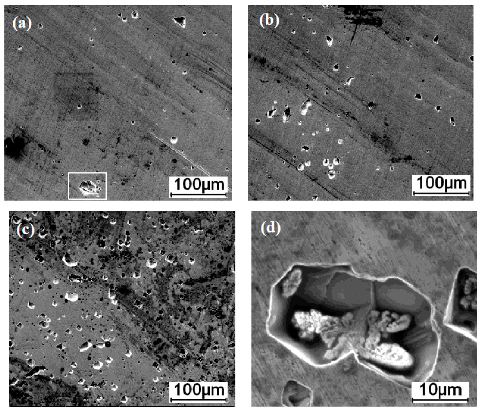
It is well known that the different microstructures could lead to the difference of corrosion behaviors from each other. To confirm these above results, optical microscopy was performed after the electrochemical experiments on passive films exposed for 72 h in aerated 1 M NaCl solution, as shown in Figure 9. For the BM there are small, circular-shaped pits with different sizes that are isolated from each other (Figure 9a). The corrosion pits of the JP specimen of corrosion pits are greater in density and larger in size (Figure 9b). It is also seen that the large density of isolated and deeper pits appear on the JP-T surface (Figure 9c). The total number of corrosion pits on the JP-T increased as compared with the JP and BM. The magnified view of the pitting corrosion of the BM surface reveals details of the morphologies of the corrosion pits (Figure 9d). The tendency of localized pitting corrosion for the three samples is consistent with the change trend of the pitting potential, that is, the pitting corrosion resistance decreases with the increase of grain size.
It is clear that BM gives better conditions than joints for forming the passive layer with higher corrosion resistance. In general, corrosion properties of materials are both influenced by the alloying elements and the grain size of the material [30]. According to classical corrosion theory, materials with nanocrystalline nature have poorer corrosion properties than bulk materials due to their higher number of electrochemical corrosion cells [31]. However, it was reported in several other studies that samples with grain sizes in the nanometer range acted differently than their bulk counterparts and the difference is mainly related to the grain size and volume fraction ratio [32]. The effect of grain size on the corrosion behavior of electrodeposited bulk nanocrystalline Ni with different grain sizes (from 16 nm to 2 μm) were emphasized in different corrosion media (NaOH and NaCl) and the results show that the Ni exhibits improved corrosion resistance with the decrease of grain size, which can be reasonably explained by the positive effect of high-density grain boundaries [23]. Indeed, fine grains in BM have a large fraction of grain boundaries compared with JP and JP-T joints. Ni is a metal that can passivate easily; the passivation first starts on the surface crystalline lattice defects and the smaller grain size has higher fractions of grain boundaries, which provide an increased number of active sites to quickly form a continuous and protective passive film that hinders Ni or electrons migrating toward the surface to participate in electrochemical reactions [33]. Thus, in the initial stage of corrosion the fine grain causes the oxidation reaction of nickel ions, which results in the formation of more nickel oxides, and the role of the structure and the actions of chemical defects, such as grain boundaries or chloride clusters, should be considered. When Cl− ions are present in the solution, they compete with OH− for adsorption on the oxide surface sites by the chemical affinity and chemical interaction, considering thermodynamic and kinetic approaches [6]. If Cl− is adsorbed on the oxide surface, the localized dissolution rate is increased and film growth is poisoned [5]. The breakdown of the film layer is ascribed to the higher Cl− adsorption. That is, Cl− penetrates the barrier layer via the inter-granular boundaries and migrates to the nickel interface to react with nickel cations, which results in a fracture of the passive film with the local outcome of pitting incursion [4,34]. These above results are consistent with consequence of the electrochemical experiments.
4. Conclusions
Conclusions drawn from the study are as follows:
- The microstructure of JP is a coarse austenite-cellular structure with an average grain size of 463.57 μm. By comparison, the JP-T is composed of a coarse austenite-columnar structure with a grain size of 547.32 μm, which is due to the increase of total heat input by the extra TIG arc, while BM has an average grain size of 47.32 μm.
- The time profiles of OCP obtained for all three samples are quite similar and all specimens in NaCl solution were gradually passivated until the OCP finally reached relatively constant values at 30 h.
- Potentiodynamic polarization curves and electrochemical impedance spectroscopy of base metal, JP, and JP-T show that JP had a relatively better corrosion resistance than JP-T, but they were lower than BM. The corrosion morphology observations are consistent with the consequence of the electrochemical experiments.
- Fine grain causes the acquisition of fine-grained samples with a large fraction of grain boundaries. The increase of the grains’ dimensions due to heat treatment decreased the metal stability to pitting corrosion.
Acknowledgments
This research is financially supported by the State Key Laboratory of Nickel and Cobalt Resources Comprehensive Utilization, China, (grant No. 301170501). The authors would like to thank Xijing Wang for his continued encouragement and permission to publish this work.
Author Contributions
Boshi Wang did these above work and wrote this paper. Xijing Wang was in charge of reviewing and revising the manuscript. Liangliang Zhang, Chao Yang, and Yan Yang contributed to the data analysis.
Conflicts of Interest
The authors declare no conflict of interests.
References
- Davis, J.R. Nickel, Cobalt, and Their Alloys; ASM International: New York, NY, USA, 2000. [Google Scholar]
- Lou, D.C.; Solberg, J.K.; Akselsen, O.M. Microstructure and property investigation of paste boronized pure nickel and Nimonic 90 superalloy. Mater. Chem. Phys. 2009, 115, 239–244. [Google Scholar] [CrossRef]
- Manoj, K. Hot corrosion of nickel in anhydrous sodium hydroxide. Mater. Chem. Phys. 1996, 45, 171–175. [Google Scholar]
- Benoît, T.O.; Catherine, A.D. Electronic and transport properties of passive films grown on different Ni-Cr binary alloys in relation to the pitting susceptibility. Electrochim. Acta 2014, 133, 373–381. [Google Scholar]
- Barbosa, M.R.; Bastos, J.A. Chloride role in the surface of nickel electrode. Electrochim. Acta 1998, 44, 957–965. [Google Scholar] [CrossRef]
- Meng, G.Z.; Yang, L.; Shao, Y.W. Effect of microstructures on corrosion behavior of nickel coatings: (II) competitive effect of grain size and twins density on corrosion behavior. J. Mater. Sci. Technol. 2016, 32, 465–469. [Google Scholar] [CrossRef]
- Meng, G.Z.; Yang, L.; Shao, Y.W. Effect of microstructures on corrosion behavior of nickel coatings: (I) abnormal grain size effect on corrosion behavior. J. Mater. Sci. Technol. 2015, 31, 1186–1192. [Google Scholar] [CrossRef]
- Li, L.; Ying, L.; Wang, F.H. Influence of grain size on the corrosion behavior of a Ni-based superalloy nanocrystalline coating in NaCl acidic solution. Electrochim. Acta 2008, 53, 2453–2462. [Google Scholar] [CrossRef]
- Tan, X.; Peng, X.; Wang, F. The effect of grain refinement on the adhesion of an alumina scale on an aluminide coating. Corros. Sci. 2014, 85, 280–286. [Google Scholar] [CrossRef]
- Aghuy, A.A.; Zakeri, M.; Moayed, M.H. Effect of grain size on pitting corrosion of 304L austenitic stainless steel. Corros. Sci. 2015, 94, 368–376. [Google Scholar] [CrossRef]
- Freire, L.; Nóvoa, X.R.; Montemor, M.F.; Carmezim, M.J. Study of passive films formed on mild steel in alkaline media by the application of anodic potentials. Mater. Chem. Phys. 2009, 114, 962–972. [Google Scholar] [CrossRef]
- Qiao, Y.; Zheng, Y.; Ke, W.; Okafor, P.C. Electrochemical behavior of high nitrogen stainless steel in acidic solution. Corros. Sci. 2009, 51, 979–986. [Google Scholar] [CrossRef]
- Marcelin, S.; Pébère, N.; Régnier, S. Electrochemical characterization of a martensitic stainless steel in a neutral chloride solution. Electrochim. Acta 2013, 87, 32–40. [Google Scholar] [CrossRef] [Green Version]
- Sun, H.; Wu, X.; Han, E. Effects of temperature on the protective property, structure and composition of the oxide film on Alloy 625. Corros. Sci. 2009, 51, 2565–2567. [Google Scholar] [CrossRef]
- Rybalka, K.V.; Beketaeva, L.A.; Davydov, A.D. Effect of self-passivation on the electrochemical and corrosion behavior of alloy C-22 in NaCl solution. Corros. Sci. 2012, 54, 161–166. [Google Scholar] [CrossRef]
- Rodríguez, M.A.; Carranza, R.M. Properties of the passive film on alloy 22 in chloride solutions obtained by electrochemical impedance. J. Electrochem. Soc. 2011, 156, 221–230. [Google Scholar] [CrossRef]
- Abd El-Haleen, S.M.; Abd El-Waness, S. Chloride induced pitting corrosion of nickel in alkaline solutions and its inhibition by organic amines. Mater. Chem. Phys. 2011, 128, 418–426. [Google Scholar] [CrossRef]
- Toni, M.; Vincent, M.; Lorena, H.K. Intergranular effects on the local electronic properties of the passive film on nickel. Corros. Sci. 2013, 69, 245–251. [Google Scholar]
- Chen, T.; John, H.; Xu, J. Influence of surface modifications on pitting corrosion behavior of nickel-base alloy 718. Part 1: Effect of machine hammer peening. Corros. Sci. 2013, 77, 230–245. [Google Scholar] [CrossRef]
- Rofagha, R.; Splonter, S.J.; Erd, U.; Mcintyre, N.S. XPS characterization of the passive film formed on nanocrystalline nickel in sulphuric acid. Nanostruct. Mater. 1994, 4, 69–78. [Google Scholar] [CrossRef]
- Rofagha, R.; Langer, R.; El-Sheerik, A.M.; Erb, G.; Palumbo, K.T. The corrosion behavior of nanocrystalline nickel. Scr. Mater. 1991, 25, 2867–2872. [Google Scholar] [CrossRef]
- Mishra, R.; Balasubramaniam, R. Effect of nanocrystalline grain size on the electrochemical and corrosion behavior of nickel. Corros. Sci. 2004, 46, 3019–3029. [Google Scholar] [CrossRef]
- Qin, L.Y.; Lian, J.S.; Jiang, Q. Effect of grain size on corrosion behavior of electrodeposited bulk nanocrystalline Ni. Trans. Nonferrous Met. Soc. China 2010, 20, 82–89. [Google Scholar] [CrossRef]
- Beverskog, B.; Bojinov, M.; Englund, A. A mixed-conduction model for oxide films on Fe, Cr and Fe-Cr alloys in high-temperature aqueous electrolytes—I. Comparison of the electrochemical behavior at room temperature and at 200 °C. Corros. Sci. 2002, 44, 1901–1921. [Google Scholar] [CrossRef]
- Elzbieta, S.; Digby, D.M. Nature of the passive film on nickel. Electrochim. Acta 2002, 48, 69–76. [Google Scholar]
- Bru, G.J.; Van, D.E.; Sluyters, R.M. The analysis of electrode impedances complicated by the presence of a constant phase element. J. Electroanal. Chem. Interfacial Electrochem. 1984, 176, 275. [Google Scholar]
- Chao, C.Y.; Lin, L.F.; Macdonald, D.D. A point defect model for anodic passive films. J. Electrochem. Soc. 1982, 129, 1874–1879. [Google Scholar] [CrossRef]
- Chen, T.; John, H.; Xu, J. Influence of surface modifications on pitting corrosion behavior of nickel-base alloy 718. Part 2: Effect of aging treatment. Corros. Sci. 2014, 78, 151–161. [Google Scholar] [CrossRef]
- Musiani, M.; Orazem, M.E.; Pébère, N. Constant-phase element behavior caused by coupled resistivity and permittivity distributions in films. J. Electrochem. Soc. 2011, 158, 424–428. [Google Scholar] [CrossRef] [Green Version]
- Murat, D. The corrosion behavior of nanocrystalline nickel based thin films. Mater. Chem. Phys. 2016, 17, 276–280. [Google Scholar]
- Herrasti, P.; Ponce, C.; Walsh, F.C. The corrosion behavior of nano-grained metals and alloys. Rev. Metal. 2012, 48, 377–394. [Google Scholar] [CrossRef]
- Wang, L.; Zhang, L.; Gao, Y.; Xue, L.; Hu, T.; Xu, T. Grain size effect in corrosion behavior of electrodeposited nanocrystalline Ni coating in alkaline solution. Scr. Mater. 2006, 55, 657–660. [Google Scholar] [CrossRef]
- Balyanov, A.; Kutnyakova, J.; Amirkhanova, N.A.; Stolyarov, V.V. Corrosion resistance of ultrafine-grained Ti. Scr. Mater. 2004, 51, 225–229. [Google Scholar] [CrossRef]
- Marcus, P.; Maurice, V.; Strehblow, H.H. Localized corrosion (pitting): A model of passivity breakdown including the role of the oxide layer nanostructure. Corros. Sci. 2008, 50, 2698–2704. [Google Scholar] [CrossRef]
Figure 1.
Schematic diagram of the corrosion testing setup.

Figure 2.
Optical micrographs showing the microstructure of (a) BM (base metal); (b) JP; and (c) JP-T.
Figure 2.
Optical micrographs showing the microstructure of (a) BM (base metal); (b) JP; and (c) JP-T.
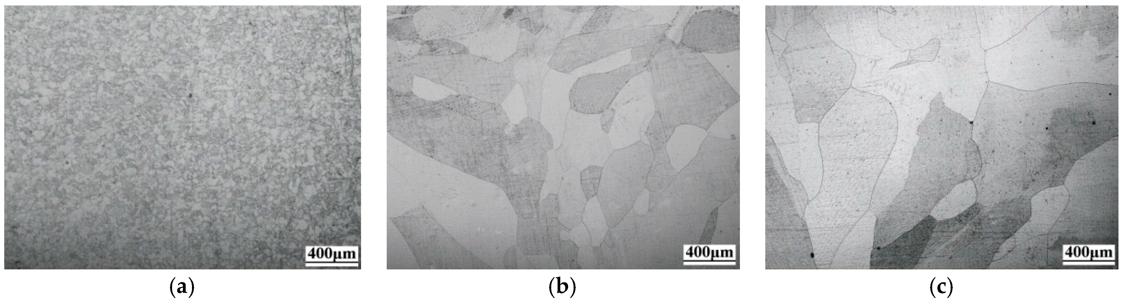
Figure 3.
Open circuit potential curves measured in 1 M NaCl solution at room temperature.
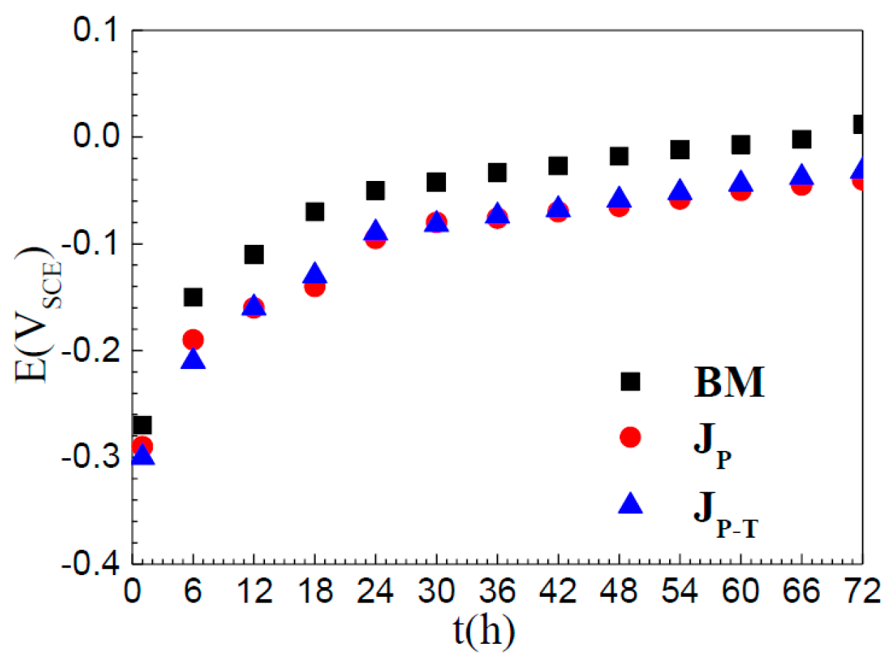
Figure 4.
Potentiodynamic polarization behavior of BM, JP, and JP-T in 1 M NaCl solution at room temperature.
Figure 4.
Potentiodynamic polarization behavior of BM, JP, and JP-T in 1 M NaCl solution at room temperature.
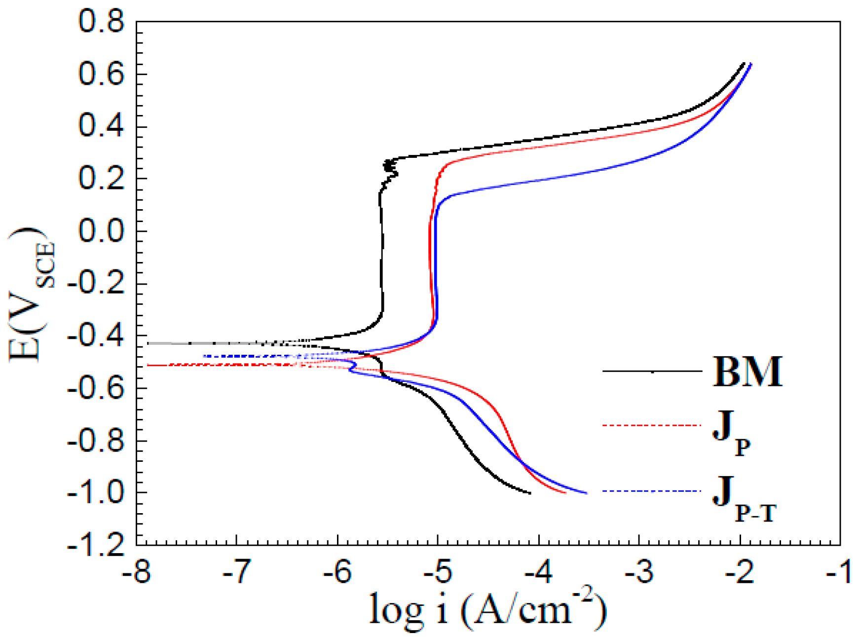
Figure 5.
EIS (electrochemical impedance spectroscopy) spectra of BM measured at OCP (open circuit potential) after different immersion times in 1 M NaCl solution.
Figure 5.
EIS (electrochemical impedance spectroscopy) spectra of BM measured at OCP (open circuit potential) after different immersion times in 1 M NaCl solution.

Figure 6.
EIS spectra of JP measured at OCP after different immersion times in 1 M NaCl solution.
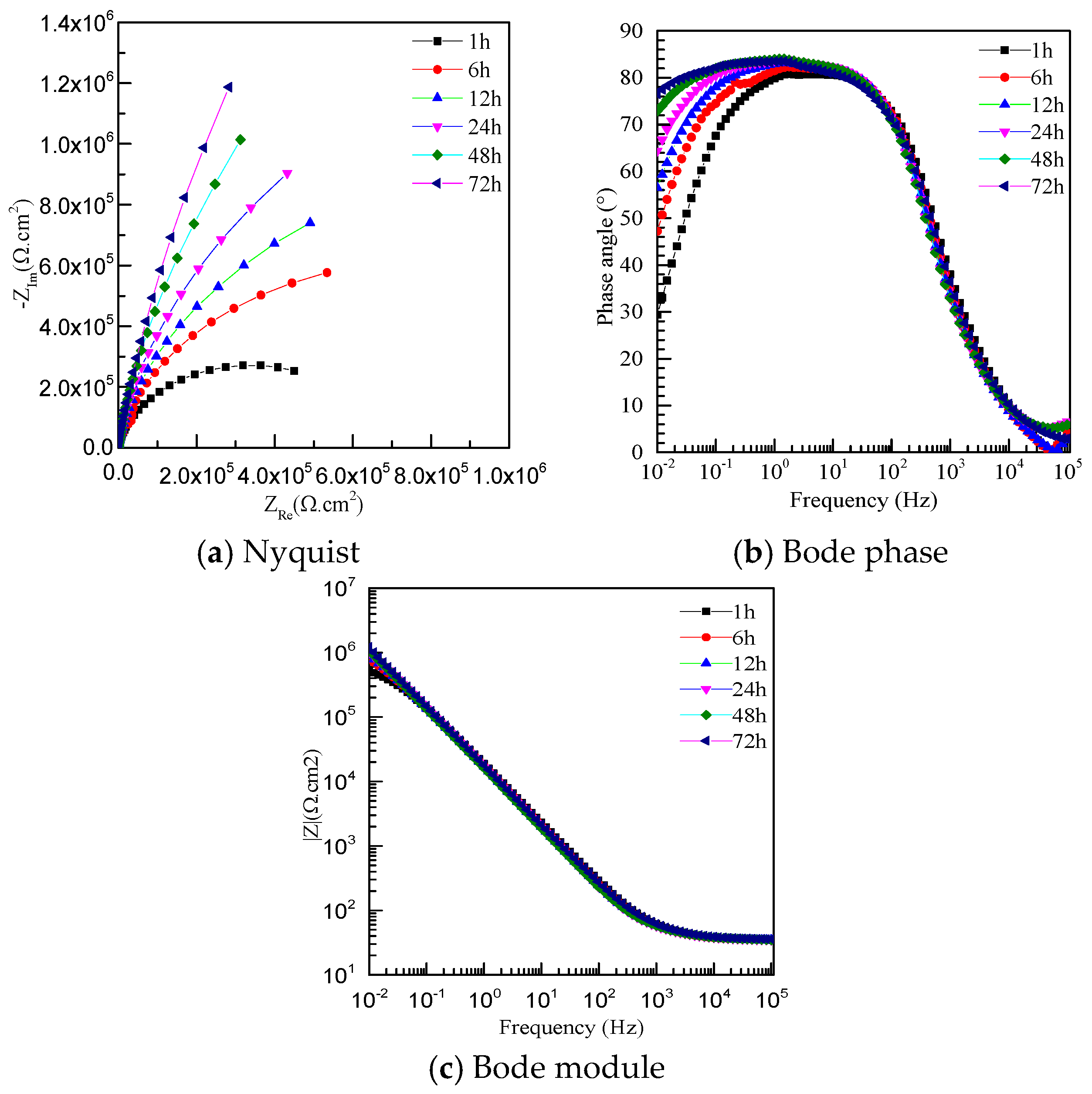
Figure 7.
EIS spectra of JP-T measured at OCP after different immersion times in 1 M NaCl solution.
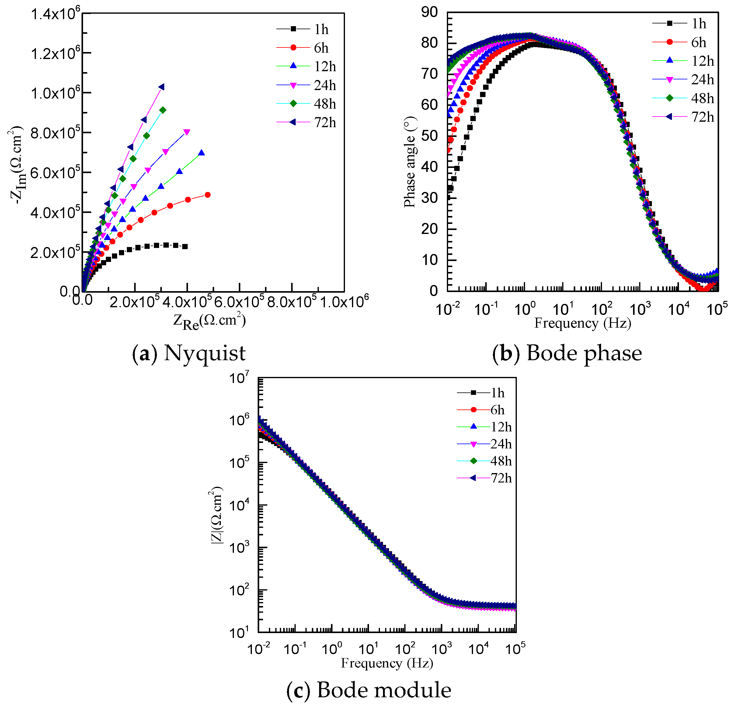
Figure 8.
Equivalent electrical circuit used for fitting the EIS data.

Figure 9.
Corrosion pitting morphologies of samples: (a) BM; (b) JP; (c) JP-T; and (d) high-magnification image of BM.
Figure 9.
Corrosion pitting morphologies of samples: (a) BM; (b) JP; (c) JP-T; and (d) high-magnification image of BM.


Table 1.
Chemical composition of BM (base metal) (wt %).
| Ni | Si | Mn | Mg | Fe | C | S | Others |
|---|---|---|---|---|---|---|---|
| 99.85 | 0.071 | 0.038 | <0.001 | 0.02 | 0.0038 | 0.01 | <0.0062 |
Table 2.
Welding parameters of different welding processes.
| Specimen | PAW Current I (A) | PAW Voltage U (V) | TIG Current I (A) | TIG Voltage U (V) | Welding Speed v (mm·s−1) |
|---|---|---|---|---|---|
| JP | 165 | 24 | - | - | 3 |
| JP-T | 160 | 24 | 195 | 13 | 6 |
Table 3.
Electrochemical parameters calculated from polarization curves in 1 M NaCl solution at room temperature.
Table 3.
Electrochemical parameters calculated from polarization curves in 1 M NaCl solution at room temperature.
| Specimen | EZCP (mV) | icorr (µA/cm2) | βc (V/dec) | ipass (µA/cm2) | Epit (mV) |
|---|---|---|---|---|---|
| BM | −428 | 7.059 | −0.582 | 2.16 | 315 |
| JP | −510 | 70.06 | −6.247 | 6.48 | 286 |
| JP-T | −477 | 71.57 | −13.873 | 7.35 | 174 |
Table 4.
Fitting EIS results for the BM, JP, and JP-T for different immersion times at OCP in 1 M NaCl solution.
Table 4.
Fitting EIS results for the BM, JP, and JP-T for different immersion times at OCP in 1 M NaCl solution.
| Specimen | Rs (Ω·cm2) | Rf (Ω·cm2) | Qf (Ω−1·cm−2·sn) | N |
|---|---|---|---|---|
| BM-1 h | 55.51 | 1.196 × 10⁶ | 4.61 | 0.87 |
| BM-6 h | 55.58 | 1.431 × 10⁶ | 6.49 | 0.87 |
| BM-12 h | 57.10 | 2.282 × 10⁶ | 6.75 | 0.88 |
| BM-24 h | 60.34 | 3.846 × 10⁶ | 6.75 | 0.88 |
| BM-48 h | 39.91 | 4.194 × 10⁶ | 9.46 | 0.88 |
| BM-72 h | 41.79 | 8.422 × 10⁶ | 8.97 | 0.88 |
| JP-1 h | 37.42 | 6.339 × 10⁵ | 10.5 | 0.89 |
| JP-6 h | 37.82 | 1.297 × 10⁶ | 11.13 | 0.90 |
| JP-12 h | 38.32 | 1.940 × 10⁶ | 11.33 | 0.91 |
| JP-24 h | 38.57 | 2.880 × 10⁶ | 11.49 | 0.91 |
| JP-48 h | 38.91 | 3.261 × 10⁶ | 11.56 | 0.91 |
| JP-72 h | 39.31 | 6.600 × 10⁶ | 10.44 | 0.90 |
| JP-T-1 h | 39.27 | 5.548 × 10⁵ | 11.17 | 0.88 |
| JP-T-6 h | 38.88 | 1.112 × 10⁶ | 11.85 | 0.89 |
| JP-T-12 h | 39.02 | 1.760 × 10⁶ | 12.01 | 0.90 |
| JP-T-24 h | 39.28 | 2.867 × 10⁶ | 12.03 | 0.90 |
| JP-T-48 h | 42.78 | 3.087 × 10⁶ | 12.00 | 0.89 |
| JP-T-72 h | 44.39 | 6.041 × 10⁶ | 11.09 | 0.89 |
© 2017 by the authors. Licensee MDPI, Basel, Switzerland. This article is an open access article distributed under the terms and conditions of the Creative Commons Attribution (CC BY) license (http://creativecommons.org/licenses/by/4.0/).
Share and Cite
MDPI and ACS Style
Wang, X.; Wang, B.; Zhang, L.; Yang, C.; Yang, Y. Effect of Different Welding Processes on Electrochemical and Corrosion Behavior of Pure Nickel in 1 M NaCl Solution. Metals 2017, 7, 532. https://doi.org/10.3390/met7120532
AMA Style
Wang X, Wang B, Zhang L, Yang C, Yang Y. Effect of Different Welding Processes on Electrochemical and Corrosion Behavior of Pure Nickel in 1 M NaCl Solution. Metals. 2017; 7(12):532. https://doi.org/10.3390/met7120532
Chicago/Turabian StyleWang, Xijing, Boshi Wang, Liangliang Zhang, Chao Yang, and Yan Yang. 2017. "Effect of Different Welding Processes on Electrochemical and Corrosion Behavior of Pure Nickel in 1 M NaCl Solution" Metals 7, no. 12: 532. https://doi.org/10.3390/met7120532
Note that from the first issue of 2016, this journal uses article numbers instead of page numbers. See further details here.