Microstructure and Mechanical Properties of Al/Steel Friction Stir Lap Weld

1
State Key Laboratory of Advanced Welding and Joining, Harbin Institute of Technology, Harbin 150001, China
2
Harbin World Wide Welding Co. Ltd., Harbin 150001, China
*
Author to whom correspondence should be addressed.
Metals 2017, 7(12), 542; https://doi.org/10.3390/met7120542
Submission received: 6 November 2017
/
Revised: 29 November 2017
/
Accepted: 30 November 2017
/
Published: 5 December 2017
(This article belongs to the Special Issue Recent Achievements in Rotary, Linear and Friction Stir Welding of Metals Alloys)
Abstract
:The friction stir welding tool with convex pin tip was designed to realize the lap joining of 6082-T6 aluminum alloy and Q235A steel. With decreasing welding speed and increasing rotation speed, the basic constitutions of mixed stir zone changed from α-Fe fine grains, thin intermetallic compound (IMC) and Al/Fe composite structure to hook-like and chaotic mixed layered structure, resulting in joint deterioration. The maximum shear load can reach 7500 N and is predominately affected by the morphology of the IMC layers, which in turn depend on rotation speed, welding speed and other parameters. Nano-hardness decreases from about 3.9 GPa in the upper steel surface layer to about 1.3 GPa in the steel base material. Microhardness profile reveals that the maximum hardness occurs at the interface zone. The morphology of layered structure, FeAl3 IMC thickness and steel grain size can be controlled by choosing suitable welding parameters and tool shape.
1. Introduction
The application of light-weight materials allows the reduction of weight and fuel consumption in automotive and aerospace industries [1,2,3]. Coelho et al. [4] pointed out that dissimilar joining of aluminum alloys and steels had become a developing trend in science and industrial application. Dilthey and Stein [5] thought that it allowed the application of these two basic engineering materials in the same design. Sajan et al. [6] pointed out that the introduction of aluminum components in chassis module and doors was an attractive eclectic choice both in cost and performance. However, the different physical properties between steel and aluminum alloy make them difficult to join together, especially by conventional fusion welding. On the other hand, solid solubility of Fe in Al is very low and it eventually leads to the formation of brittle intermetallic compounds (IMCs).
Friction stir welding (FSW) technique is a solid-state joining technique and has become an important process in the field of dissimilar metals joining [7,8]. The joint configurations of aluminum alloy and steel range from butt to lap joints. The effects of welding parameters on sound welds, mechanical properties, microstructural characterizations, material flow, and failure modes have been investigated. Habibnia et al. [9] friction stir welded 5050 Al alloy to 304 stainless steel and found out that increasing welding speed lead to better surface quality. The similar result was also found by Yasui et al. [10] who found heat input decreased with increasing welding speed, making aluminum plastic flow weaken. Liu et al. [11] analyzed effects of welding parameters on FSW joints of dissimilar aluminum alloy to advanced high strength steel and achieved sound joint which had high quality. Dehghani et al. [12] investigated the effects of parameters on IMC and defect formation in joining aluminum alloy to mild steel. Dehghani et al. [13] also pointed out that the weld nuggets were filled with large steel fragments and small platelets as a result of the abrasion and shearing by tool rotation. The chemical reaction between steel particles and plastic deformed aluminum alloy creates Al6(Fe, Mn). The effects of welding speed, plunge depth, tilt angle and tool pin geometry on the IMCs and tunnel formation, and tensile strength of joints were also investigated. Kim et al. [14] thought high heat input induced by high rotation and low welding speed lead to the formation of tunnel defect. Chen [15] studied effects of welding parameters on FSW joints of 6061-T651 aluminum alloy to SS400 steel and indicated that rotation and welding speed were relatively significant process parameters compared to the tool tilt angle and pin diameter. It is well known that welding processes have multiple responses. The relationship between the processing parameters is non-linear, thus mutli-object optimization techniques are necessary to be utilized [16,17]. In order to optimize a process with multiple responses, various multi-objective optimization techniques based on statistical and intelligent models provide good results. The model based on artificial neural networks could help to identify the relation between process parameters and quality of weld [16]. Naghibi et al. [17] used the neural network and genetic algorithm based model to realize the optimization of tensile properties of AA 5052 to AISI 304 dissimilar FSW joints.
Researchers have also studied Al/steel friction stir lap welding (FSLW) joint [18,19,20,21,22]. Kimapong and Watanabe [18] carried out that the maximum shear load of FSLW joint of 5083 aluminum alloy and SS400 mild steel could reach about 77% of aluminum alloy base metal. The FeAl, FeAl3 and Fe2Al5 IMCs existed in the interface corresponding to different tool tilt angles. Movahedi et al. [19] found that IMC layer with a thickness of less than 2 μm will not degrade joint quality. Similar results were suggested by Lee et al. [20] and they reported that 2 μm IMC layers with the composition of Fe3Al, Fe4Al13 could contribute to the joint strength. Chen et al. [21] used Zn coating on the steel surface to improve the weldability of Al and steel by means of promoting the formation of Al-Zn low melting point eutectic structure. Chen et al. [22] also found that the thickness of IMC layer increased from 7.7 to 58.1 μm with decreasing welding speed, which significantly affected the joint strength.
Clearly, finding a FSW processing window and realizing the control of interfacial structures for producing sound Al/steel joint are matters of concern. The present article investigates the interfacial characterization of FSLW joints of 6082-T6 aluminum alloy and Q235A steel, provides welding variable window for sound welds, and studies mechanical properties. The paper also investigates the interfacial structure from a metallurgical point of view.
2. Experimental Procedure
The 6082-T6 aluminum alloy plate and Q235A steel plate were chosen as the base metals, the dimensions of which are 3 mm × 300 mm × 100 mm and 2 mm × 300 mm × 100 mm, respectively. The chemical compositions of base metals were shown in Table 1.
The FSLW joints were produced by FSW-3LM-003 machine (Harbin World Wide Welding Co. Ltd., Harbin, Heilongjiang, China). M42 tool steel was selected to make the FSW tool for its good abrasion resistance and high hardness. The FSW tool had the shoulder of 14 mm in diameter with cylinder pin of 6 mm in diameter and 3.1 mm in length. The stir pin had a convex pin tip. The tool axis was tilted by 2.5° with respect to the vertical axis of the plate surface. The process parameters were as follows: the shoulder plunge depth was 0.2 mm, rotation speed was 600–1200 rpm and welding speed was 25–400 mm/min, as shown in Table 2. The schematic views of the welding tool and welding method were shown in Figure 1.
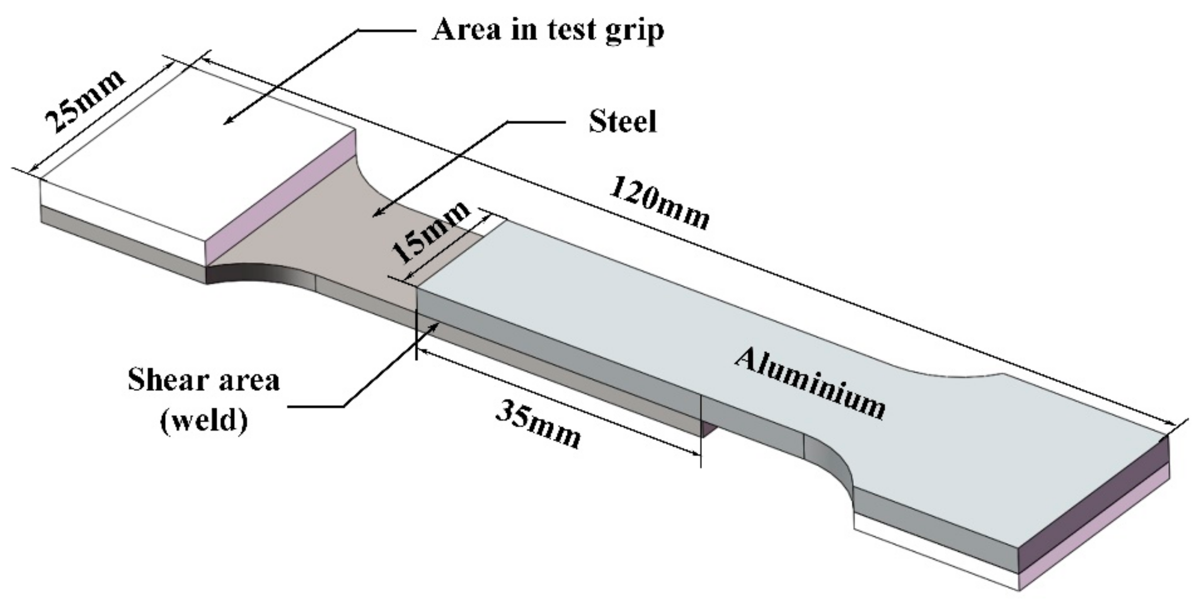
The specimens were cross sectioned perpendicular to welding direction by computer numerical control wire cutting machine according to China National Standard GB/T2651-2008 welding joint tensile test methods. Instron tensile tester with hydraulic grips was used for unguided lap shear testing of the lap weld samples. The dimension of test sample is shown in Figure 2. The room temperature tensile test was performed at a crosshead speed of 0.5 mm/min at an INSTRON-1186 (Instron engineering corporation, Shanghai, China) universal testing machine. Nano-hardness tests were performed by a nanoindenter G200 (Agilent Technologies, Beijing, China) with a maximum load of 10 g and peak hold time of 10 s. Measurements were performed pointwise over the whole cross-section of the weld. Samples for microstructural investigation were taken from FSLW joints lengthwise section. The steel side was etched by a solution (2.5 mL nitric acid + 97.5 mL ethanol), while the Al side was etched by Keller’s reagent (1 mL HF + 1.5 mL HCl + 2.5 mL HNO3 + 95 mL water). The microstructure and the elements distribution along the interface were analyzed by optical microscopy (OM, Olympus-MPG3, Olympus, Tokyo, Japan) and scanning electron microscopy (SEM, Hitachi-S4700, Hitachi, Tokyo, Japan) equipped with energy dispersive spectrometer (EDS, Hitachi, Tokyo, Japan).
3. Results and Discussion
3.1. General Features of Lap Joint
3.1.1. Macrostructure of Lap Joint
Figure 3 shows the transverse cross section of Al/steel FSLW joint, which can be divided into four typical weld zones: weld nugget zone (WNZ), mixed stir zone (MSZ), TMAZ, and HAZ. Irregular interface and thermo-mechanical interlock structure can be seen when welding speed was lower, as shown in Figure 3a. This phenomenon became gradually minimized and the saw-tooth like interface produced by steel fragments gradually disappeared with increasing welding speed or decreasing rotation speed. The macrostructure at lower welding speed (Figure 3a and Figure 4a,b) was similar to the macrostructure at higher welding speed (Figure 3b and Figure 4d). However, the hook-like structure and layered structure disappeared in the steel interface when the welding speed increased to 200 mm/min. Figure 3d shows that no obvious mechanical mixing layer existed at the interface under the condition that welding speed was 200 mm/min and rotation speed was 600 rpm. Macroscopic defects such as micro-cracks were observed, and binary IMC layers were found to exist at the Al/steel interfaces. The steel particles were stirred into the aluminum side and traveled across the interface when welding speed was lower and rotation speed was higher. Plastic deformed steel fragments were stirred by the pin and mixed with plasticized aluminum alloy.
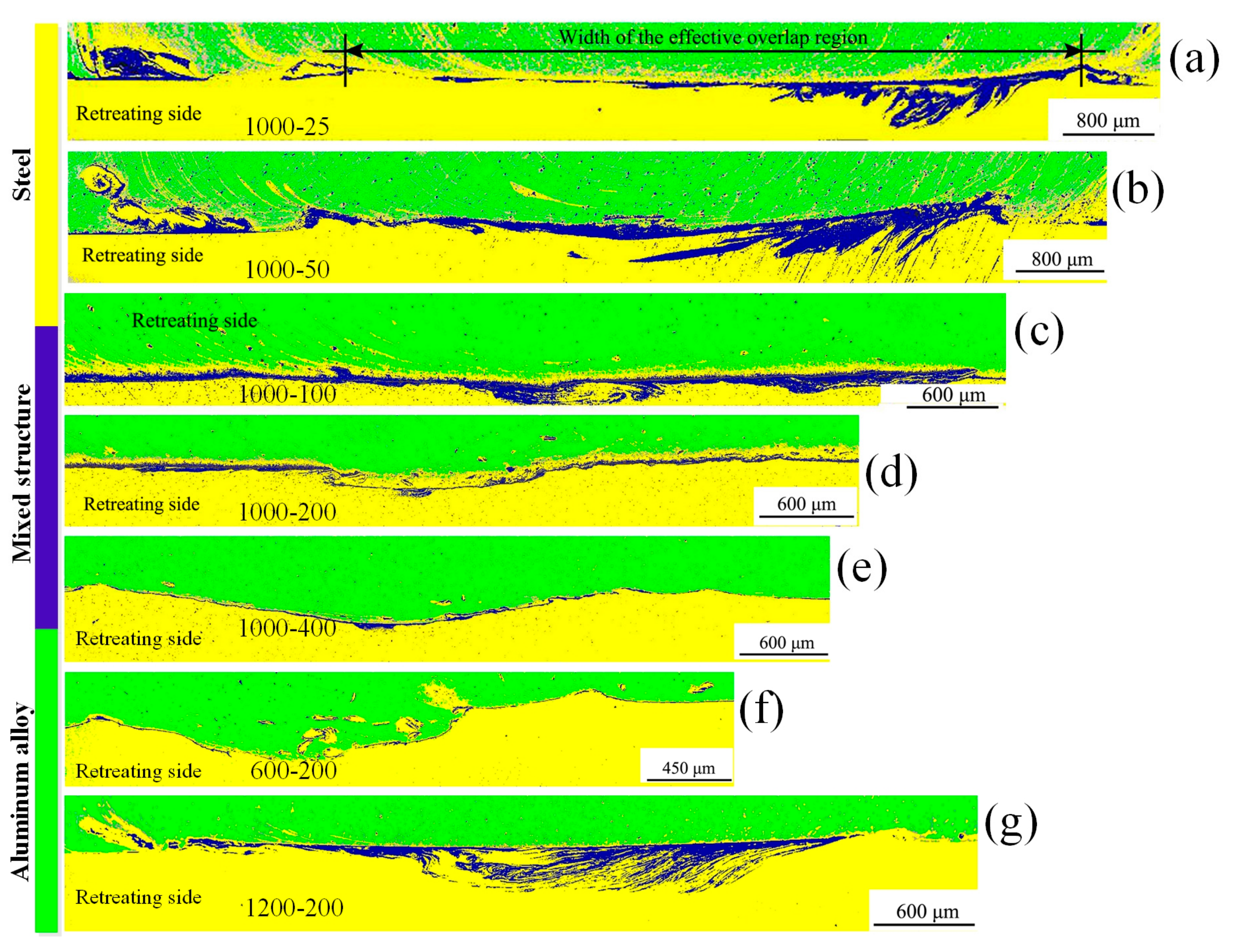
Figure 4 shows the macrostructure of the interface of lap joints. The welding parameters had a major influence on the flow and mixing of the materials. Chaotic mixed structures are present in Figure 4a,b,g. High frictional heat was generated when welding speed is low and rotation speed is high, which can make materials become plastic and mix disorder. Higher rotation speed also produced more vertical mixing between upper aluminum and lower steel. The occurrence of non-continuous IMCs and chaotic structures are more serious at the advancing side than that at the retreating side of the joint. Arora et al. [23] and Nandan et al. [24] indicated that the interfaces at the center region and advancing side under the stir pin were stirred more severely than that at retreating side. Figure 4a–e shows that when welding speed was decreased to 100 mm/min, more diffusion time and heat input were provided for the growth of IMCs along and across joint interface and non-continuous IMCs became sufficiently dense to form a continuous layer.
3.1.2. Microstructure of Lap Joint
As indicated in Figure 5, dynamic recrystallization occurs in the steel surface. The α-Fe fine grain size in the steel close to the interface can be attributed to the heavy plastic deformation produced by the rotating convex pin. The dynamic recrystallization occurred as a result of the combined effects of pin stirring and frictional heat. Furthermore, grain size increases from Al/steel interface to steel base metal due to a decrease in deformation strain rates and heat input. The WNZ in steel side also showed layers of different textures accompanied by changes in grain shape, as shown in Figure 5d–f. In Figure 5f–i, with the distance increasing from weld interface, shear texture components became less identifiable.
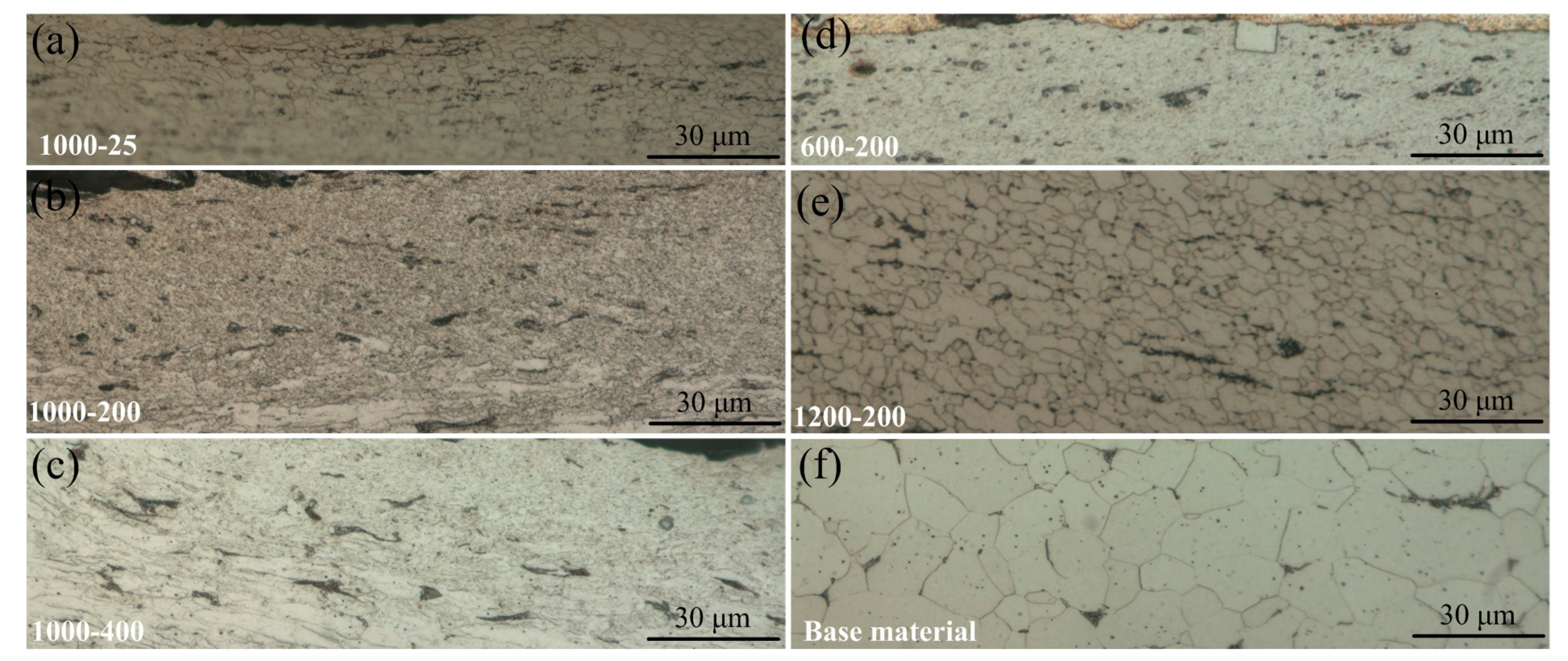
As shown in Figure 6, with the increase of rotation speed, steel grains under the interface coarsened, which was due to the increased heat input. The average grain size in fine-grain zone of the steel at a rotation speed of 1000 rpm was less than 1 μm, while it was approximately 3 μm at a rotation speed of 1200 rpm. In contrast to rotation speed, increasing welding speed decreased heat input and deformation strain rate, which in turn decreased grain size and decreased the zone area of steel fine grain.
3.2. Detailed Interfacial Macro- and Microstructure
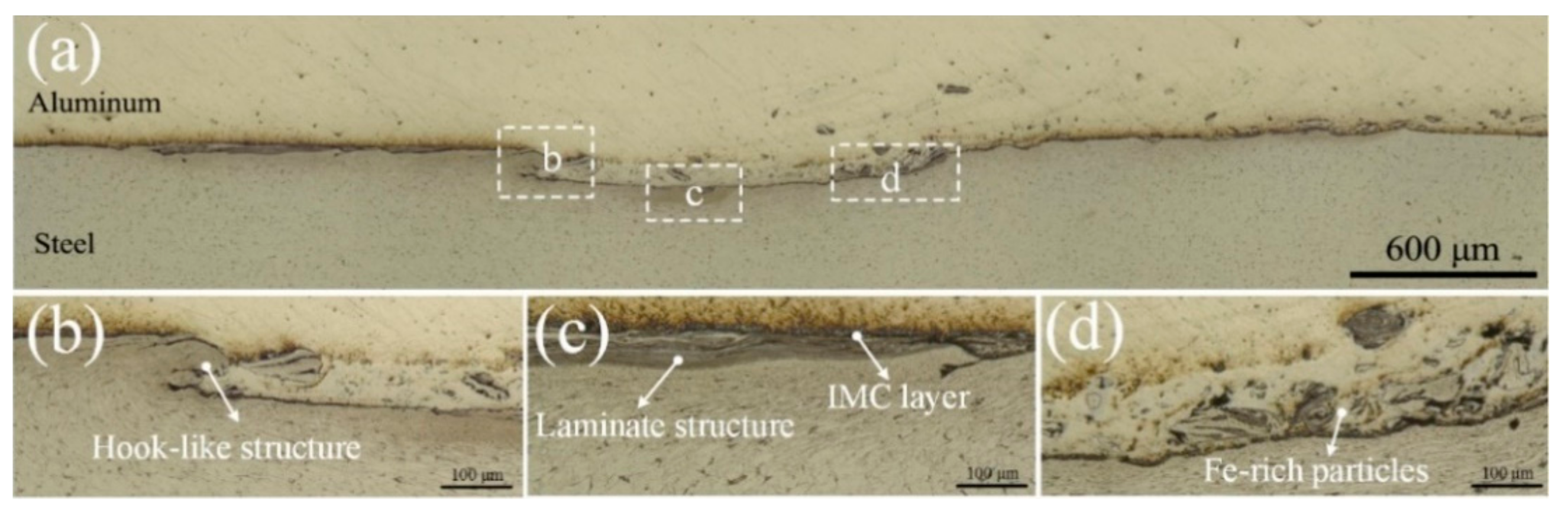
Figure 7 shows MSZ commonly observed at the Al/steel lap interface. The MSZ corresponds to the area of the pin penetrated into steel, and this zone is a mixture of thin Fe-Al intermetallic layer inserted in the recrystallized α-Fe grains. Figure 7b shows the hook-like structure resulted by the combined action of pin rotational motion and plunging of convex pin tip into steel plate. The frictional heat and heat generated from plastic deformation was enough to make the bottom steel plates soften and induced vertical motion according to the stir pin rotation, which pulled up the steel into aluminum side joint. Figure 8a–c shows the detailed hook-like features. IMCs form at the weld interface and around the edges of particles or hook-like structure stirred into the aluminum WNZ, as can be seen in Figure 8g. It can be concluded that the diffusion and chemical reaction took place between plastic aluminum alloy and severe plastic steel. The difference of hook-like structures between the retreating side and advancing side is due to asymmetric material flow around the pin. Kumar and Kailas [25] pointed out the stirring of materials had taken place from advancing side to retreating side, and stirred Al-steel mixed material was accumulated along the retreating side. Figure 7c is the middle part of the weld interface. At the interface, a thin continuous intermetallic layer was formed. Laminate structures were also found below this intermetallic layer. Figure 7d is characterized by Fe-rich particles dispersed into the aluminum matrix. Figure 8d revealed very few medium and large steel particles present in the WNZ matrix. The IMC layers surrounding the randomly steel particles in WNZ varied more dramatically in thickness, especially where the particles shapes were most turbulent, as shown in Figure 8e. This material flow causes particles sheared off from the lower steel plate to be stirred into the lower part of WNZ in aluminum alloy side, creating a composite-like structure, which can be seen in Figure 8f.
Figure 9 shows detailed interfacial microstructure of Al/steel lap joint under SEM. The presence of concave pin tip created a microstructure at the interface that is much more complex and variable than would be expected for a conventional FSW tool. The IMCs had a non-continuous morphology while some relatively continuous layers were formed at the joint interface. A swirl layered structure was formed as a result of the stirring and mixing effects of the stir pin at the interface. The more continuous and linear layered structure was formed relatively far from the interface. It evolved gradually into a wavy and folding shape near the interface and transformed to non-continuous and chaotic morphology at the weld interface. These layers are mechanical mixtures of Al and steel layers. Figure 10 revealed that a layered structure formed in the steel fine-grain zone adjacent to the weld interface. The material directly below the stir pin tip experiences both shearing and compression deformation.
Not enough time can be provided for the diffusion of Al and Fe atoms to form Al/Fe IMCs layer due to the short diffusion time. However, Figure 11 indicates the IMC formation at Al/steel interface. The Al content in the mixed layered structure measured with EDX ranged from 10 to 55 wt %, which indicated the presence of Fe3Al, FeAl and FeAl2 according to the Al-Fe binary phase diagram. It can be concluded that the fracture occurred mainly along the layer structure. The EDS chemical composition maps in Figure 12 show the overlap of aluminum atoms and iron atoms in the IMC layers. This concentration profile again showed the interdiffusion of Al and Fe atoms across the interface of mixed layered structure.
EDS point analysis of different areas (in Figure 11c) investigated the composition of the IMC layer and the laminate structures, as shown in Table 3. Spectra 1 and 3 were taken from grey layer. Composition of this layer was 49.90% Al, 45.49% Fe, and 47.62% Al, 47.35% Fe with some other minor elements. This corresponds to a FeAl intermetallic layer. Spectra 2, 4 and 5 were taken from the laminate structures. The composition of spectrum 2 showed 31.79% Al, 64.92% Fe, which indicated that this layer was mostly Fe2Al layer. Spectrum 4 and 5 showed relatively higher amount of Fe (74.62% Fe and 68.11%, respectively), which indicated this might be Fe3Al intermetallic layer. It appears that laminate structures of Fe and Fe-Al IMC formed.
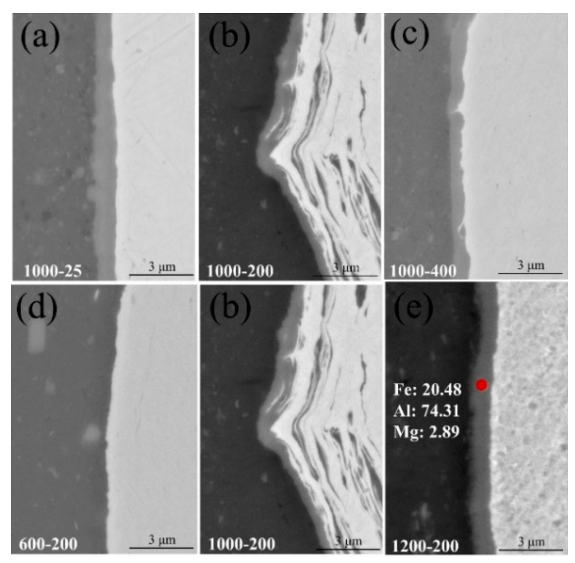
The thickness of the IMC layer played an important role in achieving joints with high quality and the IMC with a thickness of less than 10 μm could improve joint quality. However, Movahedi et al. [26] revealed that the IMC formation, regardless of their thicknesses, reduces the joint quality. There is disagreement between the results about the effects of the thickness of Al/Fe intermetallic on the joint strength. Figure 13 and Figure 14a shows that the thickness of the IMC layer at the joint interface decreased from 1.1 to 0.65 μm with the increase of welding speed from 25 to 400 mm/min. The thickness of IMC layer increased significantly from nearly 0 to 1.2 μm with the increase of rotation speed from 600 to 1200 rpm, as shown in Figure 13 and Figure 14b. The thickness of IMC layer at the joint interface depends on two major mechanisms: nucleation and growth, which are simultaneously affected by the amount of heat input, stored energy and plastic deformation degree at the joint interface. The high heat input can provide activation energy for the formation of IMCs and promotes diffusional growth of IMCs. The stored energy resulted by severe plastic deformation at the joint interface could also influence the IMCs nucleation and may increase growth rate of IMC layer as a result of atomic diffusion through high energy paths including grain boundaries and dislocations. The plastic deformation degree of the interface can be affected by the variations of rotation speed and welding speed, which finally influences the amount of the stored energy, atomic diffusion rate and the IMC nucleation, as shown in Figure 6. The increase in the rotation speed and decrease in welding speed led to the improvement of the interfacial maximum temperature. The type of Al/Fe IMCs depends on the amount of heat input. Higher heat input causes formation of thicker IMC layer, which makes the joint more brittle, and thereby decreases the joint strength. Shen et al. [27] also indicated that mechanical properties of the joints can be improved by altering the types, distribution and thickness of IMCs.
3.3. Mechanical Properties of Lap Joint
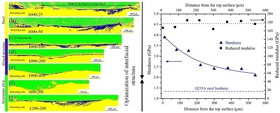
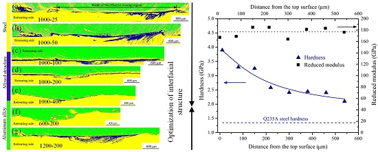
Nano-hardness and elastic modulus across the steel surface layer were also measured by using a nanoindenter with a Berkovich tip, as shown in Figure 15. The joint was achieved with rotational speed of 600 r/min and welding speed of 200 mm/min. Nano-hardness decreases from about 3.9 GPa in the upper surface layer to about 1.3 GPa in the base material. Severe plastic deformation takes place in the steel surface layer close to the interface, resulting in ultrafine structure attributed to the recrystallization of the steel after undergoing heavy plastic deformation by the rotating pin. There is plenty of evidence to indicate that a gradient microstructure composed of ultrafine structure was developed in a very thin layer on the upper steel surface layer. The elastic moduli values (about 178 GPa) of the base material and the upper steel surface layer are unchanged, independent of grain size in the present grain size regime.
The transverse microhardness distribution on cross sections of aluminum alloy side joints is shown in Figure 16a,d. The microhardness value of the 6082-T6 aluminum alloy BM is in the range of 100–105 HV. All microhardness distribution profiles are corresponding to three distinct microstructural zones and exhibit W-shape. The microhardness value of the aluminum alloy side joint has a growth tendency as the welding speed increases and rotation speed decreases. The microhardness profiles in Figure 16b,e were obtained from the Q235A steel at 0.5 mm below the weld interface. The drastic peaks and valleys in the steel BM were likely influenced by the presence of the fine grain. The average hardness in the fine-grain steel zone was 225 HV, while it was 116 HV in the base steel. Figure 16c,f shows microhardness value measured from Q235A steel to the weld surface of 6082-T6 aluminum alloy sheet in the thickness direction, at an interval of 0.5 mm. The hardness decreases gradually to the minimum (66.4 HV) from the top surface of aluminum sheet to the Al/steel interface, then increases dramatically to the maximum (349 HV) at the layered structure in the Al/steel interface, and then drops to another minimum (182.3 HV) in the HAZ of the steel, and then increases to the steel hardness of up to 200 HV. The sudden increase in microhardness near the weld interface was assumed to be the existence of small steel particles and IMCs. This is related to the formation of IMCs within this structure as suggested by SEM analyses. Microhardness profile reveals that the maximum hardness occurs at the interface zone, which indicates the brittle nature of the IMCs.
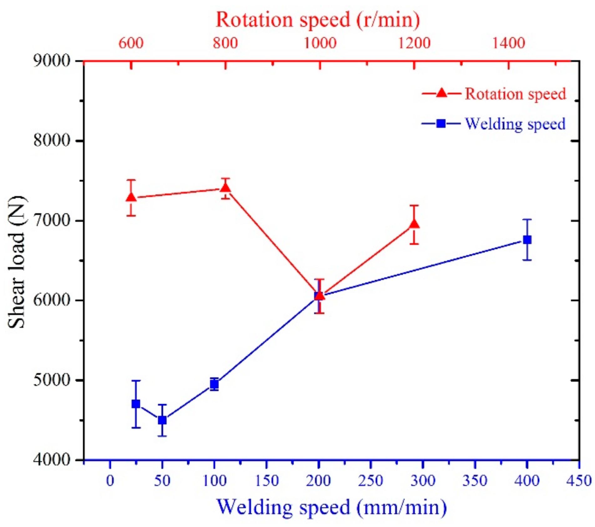
The average shear loads of the testing samples with various welding speeds and rotation speeds are presented in Figure 17. Although the measured values of failure loads were scattered, they showed a tendency to increase slightly with increasing welding speed from 25 to 400 mm/min. As indicated in Figure 4a,b, chaotic mixed structures with a mass of defects such as cracking and voids, were produced on the advancing side when welding speed is lower than 100 mm/min, which counteracts the contribution of the mechanical interlocking effect and is responsible for the deterioration of joint strength. However, Liyanage et al. [28] indicated that plastic deformation of the steel surface (Figure 6) during the FSLW process will promote mechanical interlocking, which will contribute to joint strength. Haghshenas et al. [29] pointed out that the high heat input will promote the formation of IMCs when aluminum alloys and steels are joined together, which may contain pre-existing cracks, have high hardness, and thus limit joint strength. Since at higher welding speed, heat input and thermal cycle decrease which reduces the IMCs thickness and interfacial complexity. With an increase in rotation speed, the ultimate shear load value gradually increased and then decreased. Increasing rotation speed from 600 to 800 rpm improved joint strength, although a further increase from 800 to 1000 rpm caused a decrease in fracture load. Maximum shear load of 7500 N was achieved with rotation speed of 800 rpm and welding speed of 200 mm/min. The combined effects of stirring action, frictional heat and pressure restrained the formation of IMC layers in the interfacial zone between aluminum alloy and steel, providing a strong joint with high quality.
4. Conclusions
In this study, the FSLW joints of 6082-T6 aluminum alloy and Q235A steel have been investigated and the following results can be summarized:
- (1)
- The basic constitutions of mixed stir zone changed from α-Fe fine grains, thin intermetallic compound (IMC) layer and Al/Fe composite structure to hook-like and chaotic mixed layered structure with decreasing the welding speed from 400 to 25 mm/min and increasing rotation speed from 600 to 1200 rpm.
- (2)
- The maximum shear load can reach 7500 N because of combined effects of stirring action, frictional heat and pressure. The nano-hardness of ultrafine structure in the steel surface layer close to the interface can reach about 3.9 GPa. The decrease of heat input and strain rate can improve joint strength, minimize the thickness of FeAl3 intermetallic layer at the interface and decrease steel grain size.
- (3)
- The sharp loss of the joint strength could not be completely attributed to the formation of a relatively thick and continuous IMC layer, but also the grain growth adjacent to steel grain size at the joint interface.
- (4)
- The morphology of layered structure, thickness of FeAl3 IMC layer and steel grain size at the interface can be controlled by selecting suitable welding parameters.
Acknowledgments
The work was jointly supported by the National Natural Science Foundation of China (No. 51575132).
Author Contributions
Long Wan and Yongxian Huang conceived and designed the experiments; Long Wan performed the experiments; Long Wan analyzed the data; Long Wan contributed reagents/materials/analysis tools; Long Wan wrote the paper. Authorship must be limited to those who have contributed substantially to the work reported.
Conflicts of Interest
The authors declare no conflict of interest.
References
- Barnes, T.A.; Pashby, I.R. Joining techniques for aluminum spaceframes used in automobiles: Part I—Solid and liquid phase welding. J. Mater. Process. Technol. 2000, 99, 62–71. [Google Scholar] [CrossRef]
- Lan, S.H.; Liu, X.; Ni, J. Microstructural evolution during friction stir welding of dissimilar aluminum alloy to advanced high-strength steel. Int. J. Adv. Manuf. Technol. 2016, 82, 2183–2193. [Google Scholar] [CrossRef]
- Yazdipour, A.; Heidarzadeh, A. Dissimilar butt friction stir welding of Al 5083-H321 and 316L stainless steel alloys. Int. J. Adv. Manuf. Technol. 2016, 87, 3105–3112. [Google Scholar] [CrossRef]
- Coelho, R.S.; Kostka, A.; dos Santos, J.F.; Kaysser-Pyzalla, A. Friction stir dissimilar welding of aluminium alloy to high strength steels: Mechanical properties and their relation to microstructure. Mater. Sci. Eng. A 2012, 556, 175–183. [Google Scholar] [CrossRef]
- Dilthey, U.; Stein, L. Multimaterial car body design: Challenge for welding and joining. Sci. Technol. Weld. Join. 2006, 11, 135–142. [Google Scholar] [CrossRef]
- Sajan, S.G.; Meshram, M.; Srinivas, P.P.; Dey, S.R. Friction Stir Welding of aluminum 6082 with mild steel and its joint analyses. Int. J. Adv. Mater. Manuf. Charact. 2013, 3, 189–193. [Google Scholar]
- Mishra, R.S.; Ma, Z.Y. Friction stir welding and processing. Mater. Sci. Eng. R 2005, 50, 1–78. [Google Scholar] [CrossRef]
- Nandan, R.; DebRoy, T.; Bhadeshia, H.K.D.H. Friction stir welding and processing. Prog. Mater. Sci. 2008, 53, 980–1023. [Google Scholar] [CrossRef]
- Habibnia, M.; Shakeri, M.; Nourouzi, S.; Besharati Givi, M.K. Microstructural and mechanical properties of friction stir welded 5050 Al alloy and 304 stainless steel plates. Int. J. Adv. Manuf. Technol. 2015, 76, 819–829. [Google Scholar] [CrossRef]
- Yasui, T.; Tsubaki, M.; Fukumoto, M.; Shimoda, Y.; Ishii, T. High-speed weldability between 6063 and S45C by friction stir welding. Weld. Int. 2006, 20, 284–289. [Google Scholar] [CrossRef]
- Liu, X.; Lan, S.H.; Ni, J. Analysis of process parameters effects on friction stir welding of dissimilar aluminum alloy to advanced high strength steel. Mater. Des. 2014, 59, 50–62. [Google Scholar] [CrossRef]
- Dehghani, M.; Amadeh, A.; Akbari Mousavi, S.A.A. Investigations on the effects of friction stir welding parameters on intermetallic and defect formation in joining aluminum alloy to mild steel. Mater. Des. 2013, 49, 433–441. [Google Scholar] [CrossRef]
- Dehghani, M.; Akbari Mousavi, S.A.A.; Amadeh, A. Effects of welding parameters and tool geometry on properties of 3003-H18 aluminum alloy to mild steel friction stir weld. Trans. Nonferrous Met. Soc. China 2013, 23, 1957–1965. [Google Scholar] [CrossRef]
- Kim, Y.G.; Fujii, H.; Tsumur, T.; Komzaki, T.; Nakata, K. Three defect types in friction stir welding of aluminum die casting alloy. Mater. Sci. Eng. A 2006, 415, 250–254. [Google Scholar] [CrossRef]
- Chen, T. Process parameters study on FSW joint of dissimilar metals for aluminum-steel. J. Mater. Sci. 2009, 44, 2573–2580. [Google Scholar] [CrossRef]
- Filippis, L.A.C.D.; Serio, L.M.; Facchini, F.; Mummolo, G.; Ludovico, A.D. Prediction of the Vickers Microhardness and Ultimate Tensile Strength of AA5754 H111 Friction Stir Welding Butt Joints Using Artificial Neural Network. Materials 2016, 9, 915. [Google Scholar] [CrossRef] [PubMed]
- Naghibi, H.D.; Shakeri, M.; Hosseinzadeh, M. Neural network and genetic algorithm based modeling and optimization of tensile properties in FSW of AA 5052 to AISI 304 dissimilar joints. Trans. Indian Inst. Met. 2016, 69, 891–900. [Google Scholar] [CrossRef]
- Kimapong, K.; Watanabe, T. Effect of welding process parameters on mechanical property of FSW lap joint between aluminum alloy and steel. Mater. Trans. 2005, 46, 2211–2217. [Google Scholar] [CrossRef]
- Movahedi, M.; Kokabi, A.; Reihani, S.; Najafi, H. Effect of tool travel and rotation speeds on weld zone defects and joint strength of aluminium steel lap joints made by friction stir welding. Sci. Technol. Weld. Join. 2012, 17, 162–167. [Google Scholar] [CrossRef]
- Lee, C.Y.; Choi, D.H.; Yeon, Y.M.; Jung, S.B. Dissimilar friction stir spot welding of low carbon steel and Al-Mg alloy by formation of IMCs. Sci. Technol. Weld. Join. 2009, 14, 216–220. [Google Scholar] [CrossRef]
- Chen, Y.C.; Komazaki, T.; Tsumura, T.; Nakata, K. Role of zinc coat in friction stir lap welding Al and zinc coated steel. Mater. Sci. Technol. 2008, 24, 33–39. [Google Scholar] [CrossRef]
- Chen, Y.C.; Komazaki, T.; Kim, Y.G.; Tsumura, T.; Nakata, K. Interface microstructure study of friction stir lap joint of AC4C cast aluminum alloy and zinc-coated steel. Mater. Chem. Phys. 2008, 111, 375–380. [Google Scholar] [CrossRef]
- Arora, A.; Zhang, Z.; De, A.; Debroy, T. Strains and strain rates during friction stir welding. Scr. Mater. 2009, 61, 863–866. [Google Scholar] [CrossRef]
- Nandan, R.; Roy, G.G.; Lienert, T.J.; Debroy, T. Three-dimensional heat and material flow during friction stir welding of mild steel. Acta Mater. 2007, 55, 883–895. [Google Scholar] [CrossRef]
- Kumar, K.; Kailas, S.V. The role of friction stir welding tool on material flow and weld formation. Mater. Sci. Eng. A 2008, 485, 367–374. [Google Scholar] [CrossRef]
- Movahedi, M.; Kokabi, A.H.; Seyed Reihani, S.M.; Cheng, W.J.; Wang, C.J. Effect of annealing treatment on joint strength of aluminum/steel friction stir lap weld. Mater. Des. 2013, 44, 487–492. [Google Scholar] [CrossRef]
- Shen, Z.; Chen, Y.; Haghshenas, M.; Gerlich, A.P. Role of welding parameters on interfacial bonding in dissimilar steel/aluminum friction stir welds. Eng. Sci. Technol. Int. J. 2015, 18, 270–277. [Google Scholar] [CrossRef]
- Liyanage, T.; Kilbourne, J.; Gerlich, A.P.; North, T.H. Joint formation in dissimilar Al alloy/steel and Mg alloy/steel friction stir spot welds. Sci. Technol. Weld. Join. 2009, 14, 500–508. [Google Scholar] [CrossRef]
- Haghshenas, M.; Abdel-Gwad, A.; Omran, A.M.; Gökçe, B.; Sahraeinejad, S.; Gerlich, A.P. Friction stir weld assisted diffusion bonding of 5754 aluminum alloy to coated high strength steels. Mater. Des. 2014, 55, 442–449. [Google Scholar] [CrossRef]
Figure 1.
(a) The geometry shape and size of the designed tool; (b) the illustration of lap welding method.
Figure 1.
(a) The geometry shape and size of the designed tool; (b) the illustration of lap welding method.
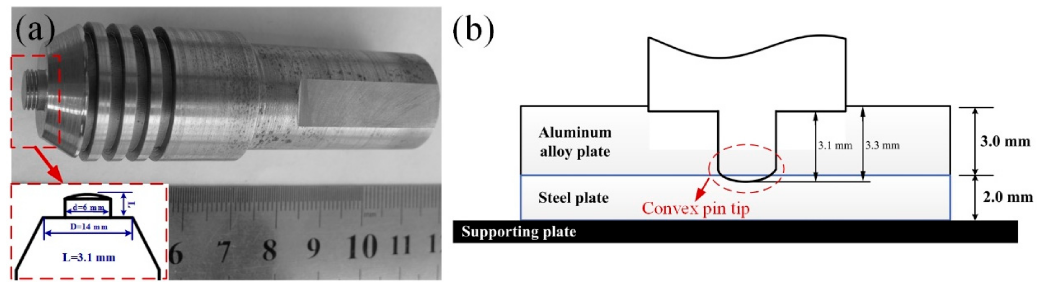
Figure 2.
Dimensions of lap shear test sample.

Figure 3.
The comparison of macrostructure of Al/steel lap joint with different welding parameters. (a) 1000 rpm, 25 mm/min; (b) 1000 rpm, 200 mm/min; (c) 1000 rpm, 400 mm/min; and (d) 600 rpm, 200 mm/min.
Figure 3.
The comparison of macrostructure of Al/steel lap joint with different welding parameters. (a) 1000 rpm, 25 mm/min; (b) 1000 rpm, 200 mm/min; (c) 1000 rpm, 400 mm/min; and (d) 600 rpm, 200 mm/min.
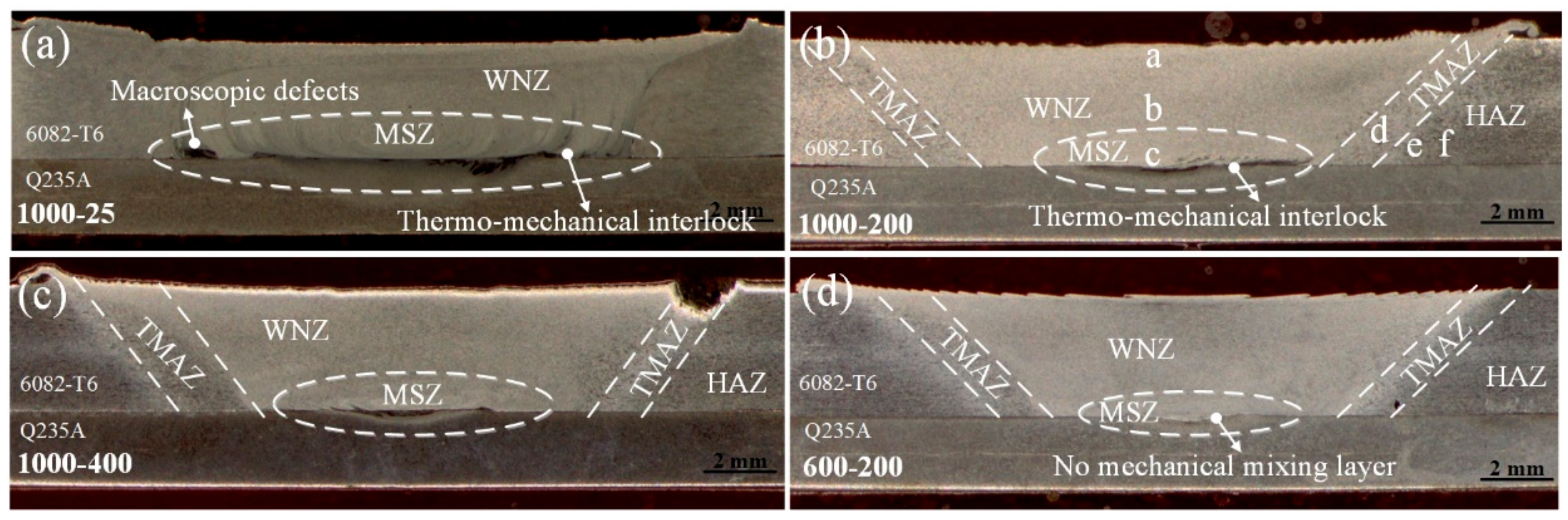
Figure 4.
Macrographs of the joint interface showing distinctive interfacial features for weld made with different welding speeds and rotation speeds.
Figure 4.
Macrographs of the joint interface showing distinctive interfacial features for weld made with different welding speeds and rotation speeds.

Figure 5.
Interfacial microstructures of Al/steel lap joint with rotation speed of 1000 rpm and welding speed of 200 mm/min. (a–c) aluminum alloy side joint; (d) plastic deformed layer of steel side joint on retreating side; (e) plastic deformed layer of steel side joint in the center; and (f–i) higher magnifications shown in (e).
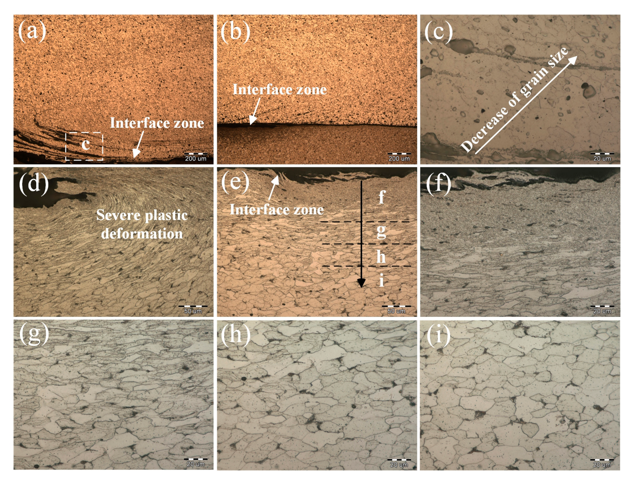
Figure 6.
The variation of steel fine grain zone with different welding parameters. (a) 1000 rpm, 25 mm/min; (b) 1000 rpm, 200 mm/min; (c) 1000 rpm, 400 mm/min; (d) 600 rpm, 200 mm/min; (e) 1200 rpm, 200 mm/min; and (f) steel base material.
Figure 6.
The variation of steel fine grain zone with different welding parameters. (a) 1000 rpm, 25 mm/min; (b) 1000 rpm, 200 mm/min; (c) 1000 rpm, 400 mm/min; (d) 600 rpm, 200 mm/min; (e) 1200 rpm, 200 mm/min; and (f) steel base material.

Figure 7.
Interfacial macro-microstructures of Al/Fe lap joint with rotation speed of 1000 rpm and welding speed of 200 mm/min. (a) interfacial macrostructure; (b) hook-like feature; (c) laminate structure; and (d) particles composite-like structure.
Figure 7.
Interfacial macro-microstructures of Al/Fe lap joint with rotation speed of 1000 rpm and welding speed of 200 mm/min. (a) interfacial macrostructure; (b) hook-like feature; (c) laminate structure; and (d) particles composite-like structure.

Figure 8.
Detailed hook-like structure and composite-like structure of Al/steel lap joint. (a) Before corrosion; (b) after corrosion; (c) reaction between hook-like structure and severe plastic steel; (d) the steel particles; (e,f) large steel particles with turbulent small particles; and (g) IMCs formation at the weld interface.
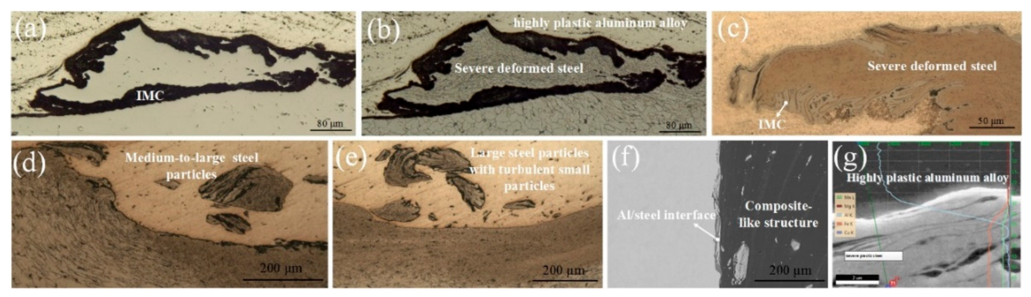
Figure 9.
Interfacial macro- and microstructure of Al/steel lap joint with the rotation speed of 1200 rpm and welding speed of 200 mm/min. (a) Interfacial macrostructure; (b) non-continuous layer; (c) wavy and folding layer; and (d) linear continuous layer.
Figure 9.
Interfacial macro- and microstructure of Al/steel lap joint with the rotation speed of 1200 rpm and welding speed of 200 mm/min. (a) Interfacial macrostructure; (b) non-continuous layer; (c) wavy and folding layer; and (d) linear continuous layer.
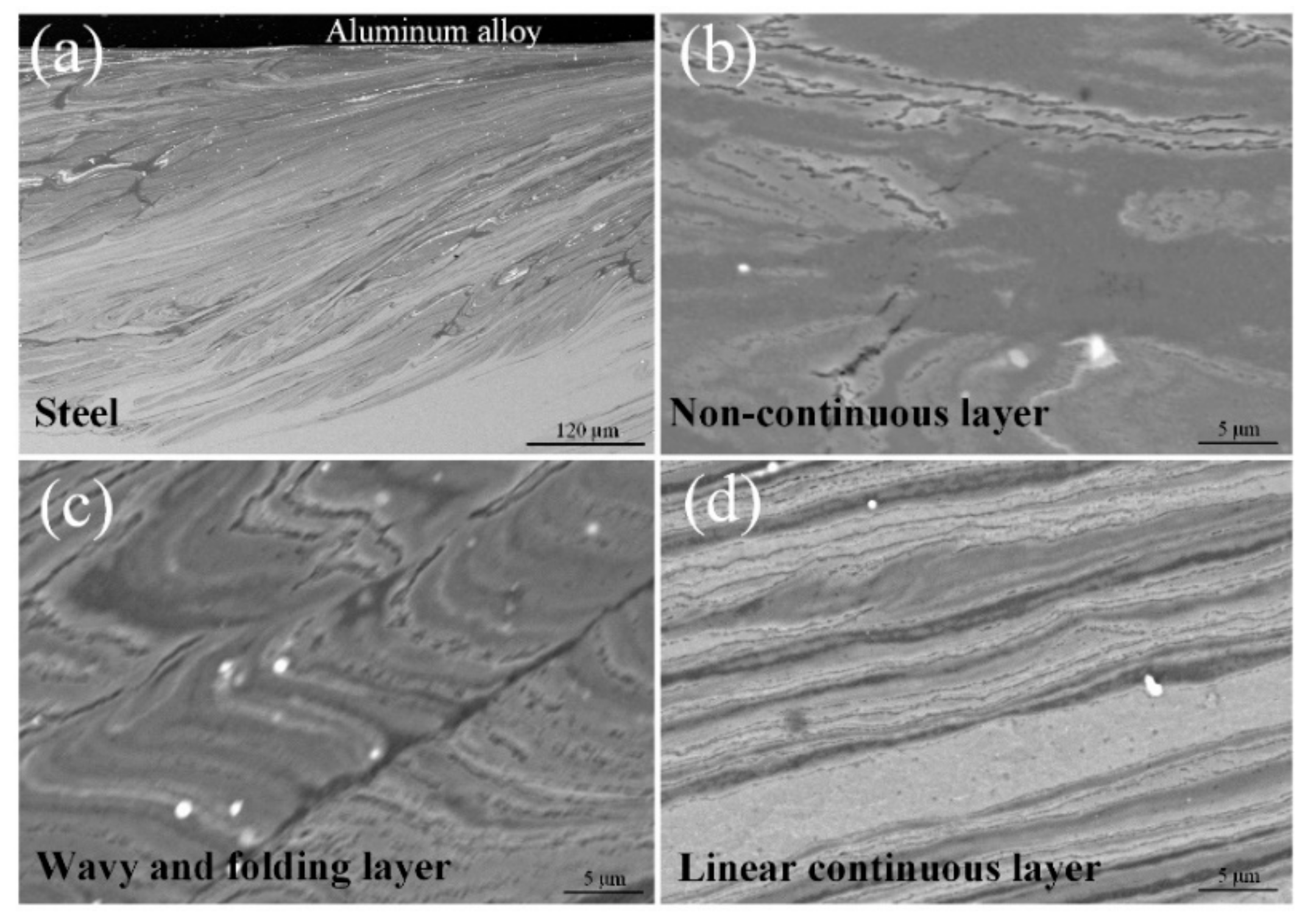
Figure 10.
Mixed layered structure showing fine steel grain. (a) Middle part of interfacial zone; (b) advancing side of interfacial zone.
Figure 10.
Mixed layered structure showing fine steel grain. (a) Middle part of interfacial zone; (b) advancing side of interfacial zone.
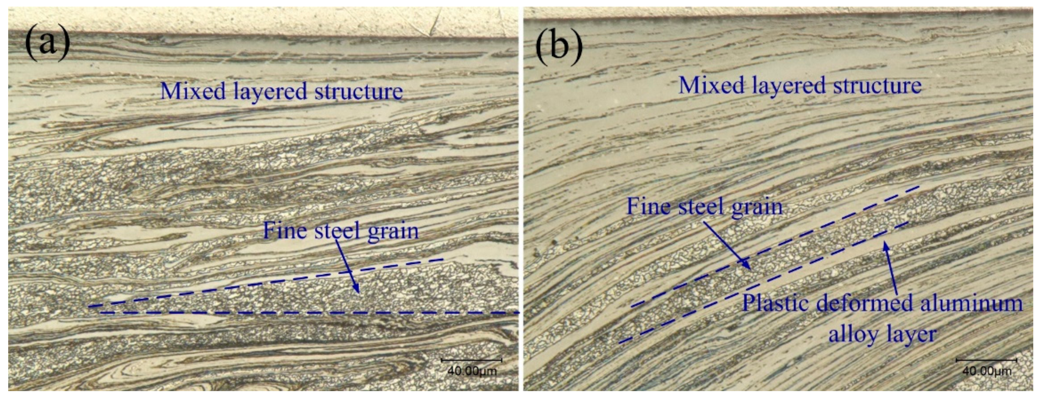
Figure 11.
Scanning electron microscopy (SEM) line scanning results. (a) macrostructure of the interface at the center of the joint; (b) macrostructure of the interface on retreating side of the joint; (c) the layered structure at the interface; and (d–f) the line scan results.
Figure 11.
Scanning electron microscopy (SEM) line scanning results. (a) macrostructure of the interface at the center of the joint; (b) macrostructure of the interface on retreating side of the joint; (c) the layered structure at the interface; and (d–f) the line scan results.
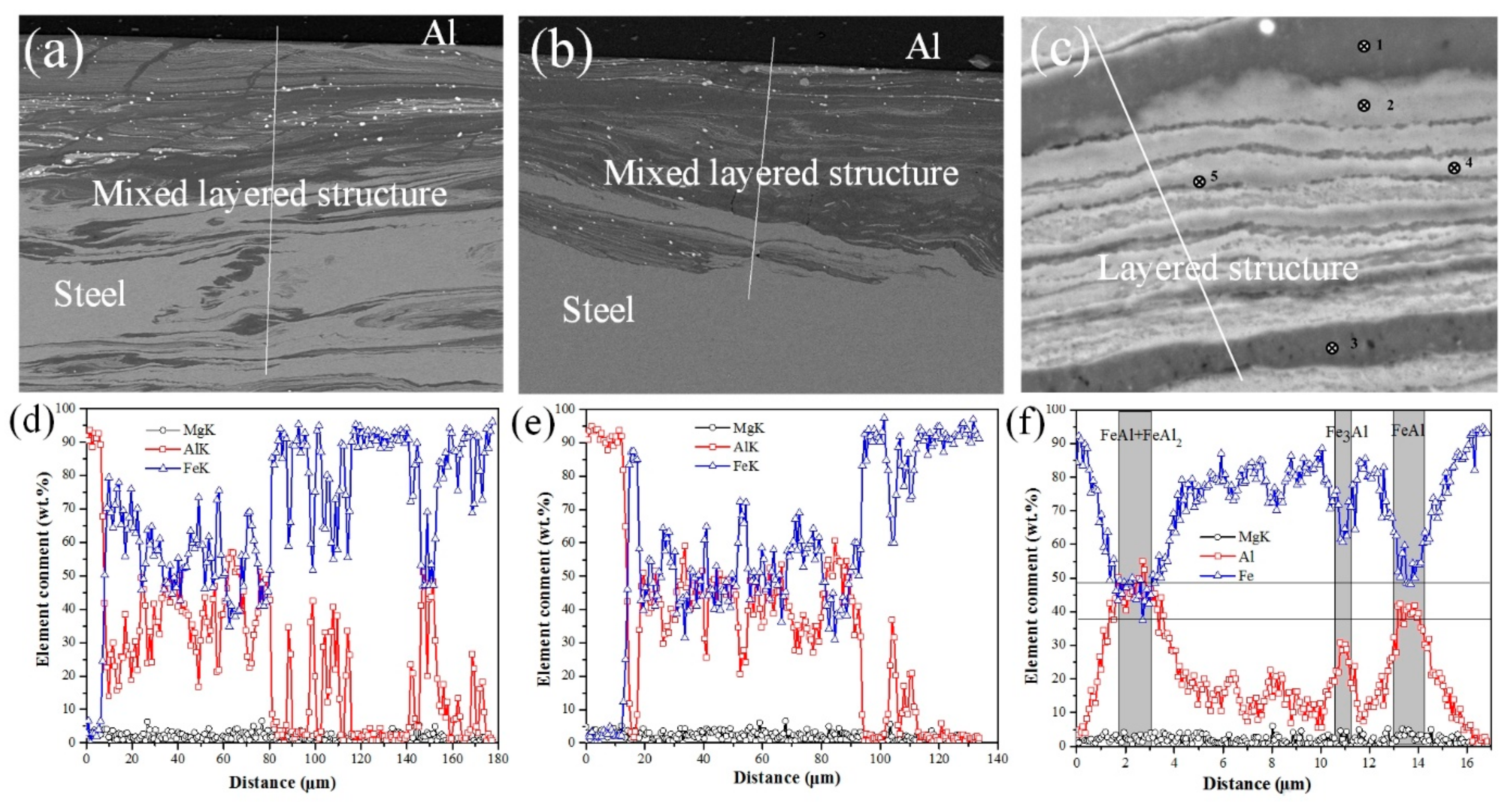
Figure 12.
Chemical maps of the layered structure. (a) The composite map showing initial structure; (b) element Fe; and (c) element Al.
Figure 12.
Chemical maps of the layered structure. (a) The composite map showing initial structure; (b) element Fe; and (c) element Al.
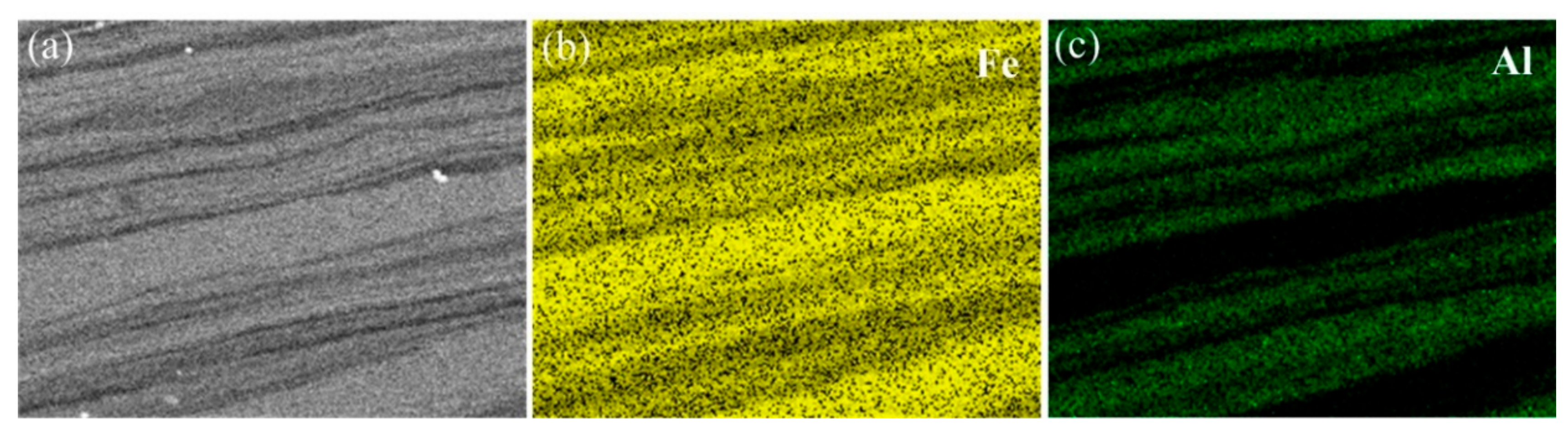
Figure 13.
The variation of IMC thickness at the interface with different welding parameters. (a) 1000 rpm, 25 mm/min; (b) 1000 rpm, 200 mm/min; (c) 1000 rpm, 400 mm/min; (d) 600 rpm, 200 mm/min; and (e) 1200 rpm, 200 mm/min.
Figure 13.
The variation of IMC thickness at the interface with different welding parameters. (a) 1000 rpm, 25 mm/min; (b) 1000 rpm, 200 mm/min; (c) 1000 rpm, 400 mm/min; (d) 600 rpm, 200 mm/min; and (e) 1200 rpm, 200 mm/min.

Figure 14.
The variation of IMC thickness at the interface with different welding parameters. (a) Variation of the welding speed; and (b) variation of the rotation speed.
Figure 14.
The variation of IMC thickness at the interface with different welding parameters. (a) Variation of the welding speed; and (b) variation of the rotation speed.
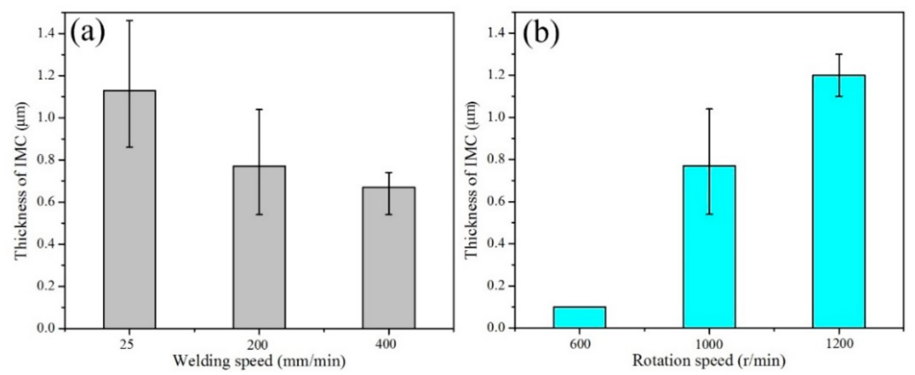
Figure 15.
Variation of the nano-hardness and elastic moduli between the upper steel surface and steel base material.
Figure 15.
Variation of the nano-hardness and elastic moduli between the upper steel surface and steel base material.
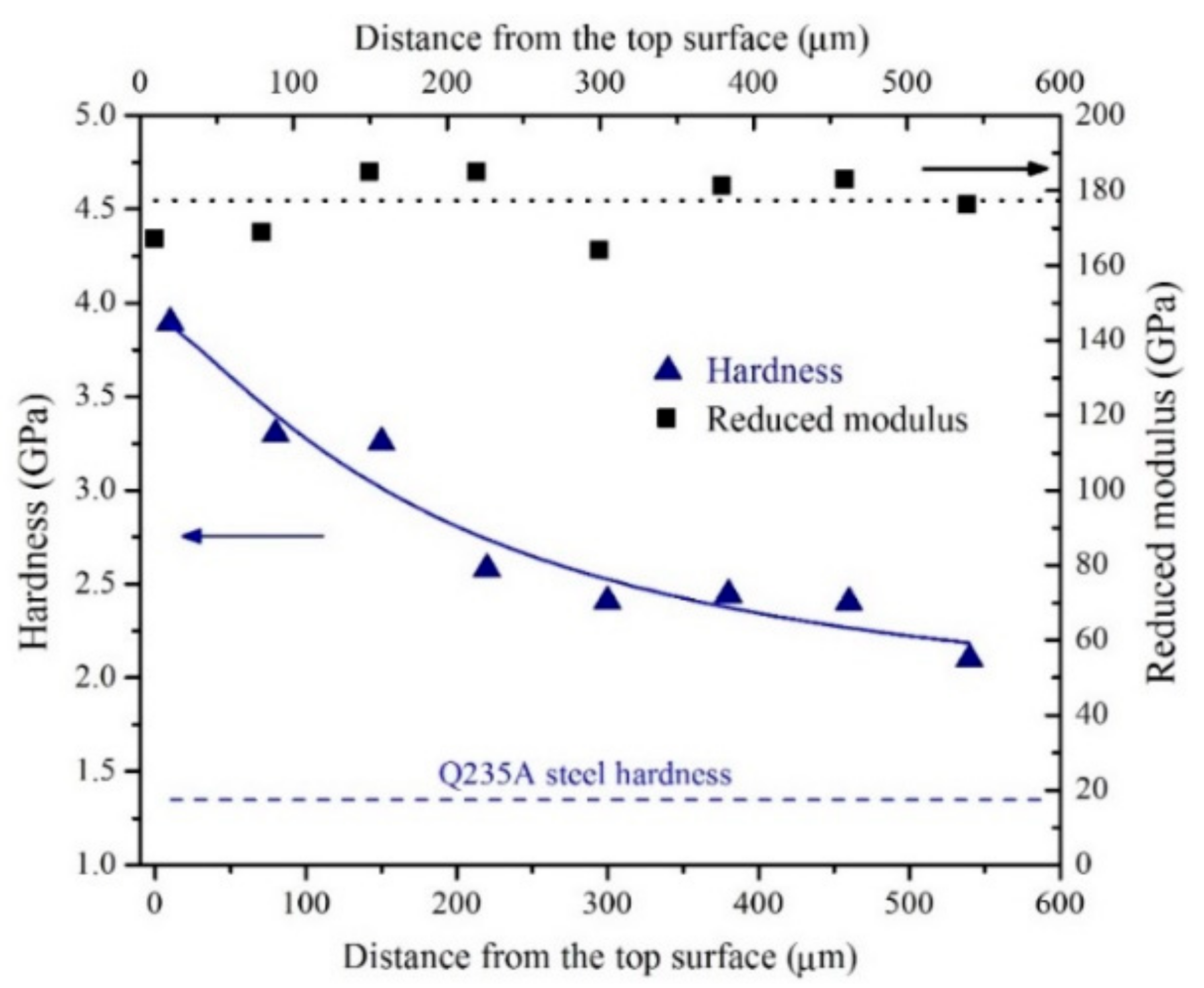
Figure 16.
The microhardness distribution of Al/steel lap joints with different rotation speeds and welding speeds. (a–e) are transverse microhardness distribution; (c,f) are microhardness distribution through the thickness. (a) Al side joint with different welding speeds; (b) Q235A steel at 0.5 mm below the weld interface with different welding speeds; (c) microhardness distribution in thickness direction with different welding speeds; (d) Al side joint with different rotation speeds; (e) Q235A steel at 0.5 mm below the weld interface with different rotation speeds; and (f) microhardness distribution in thickness direction with different rotation speeds.
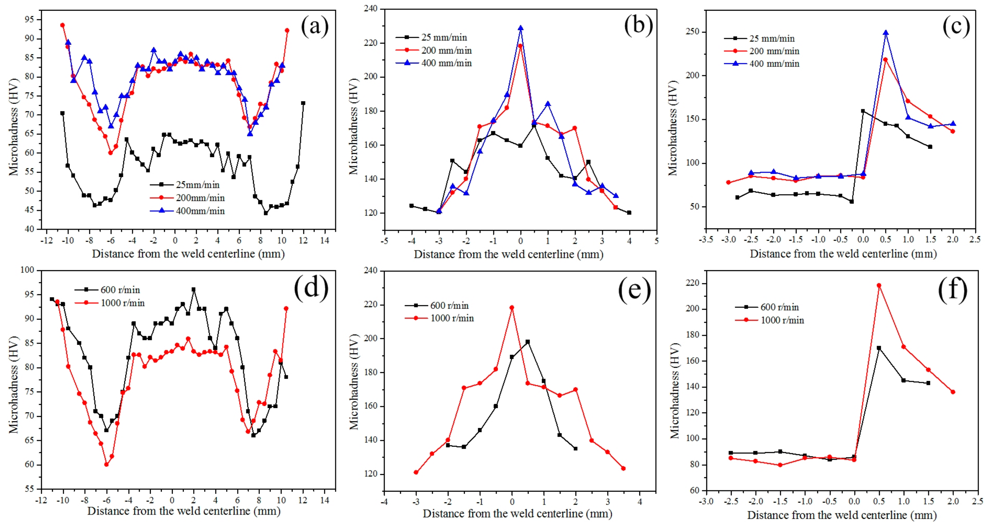
Figure 17.
The variation of shear load with different welding parameters.

Table 1.
Chemical composition of base materials.
| Base Metal | Chemical Compositions (wt %) | ||||||||||
|---|---|---|---|---|---|---|---|---|---|---|---|
| Fe | Al | Si | Mg | C | Mn | Cu | Cr | Ti | P | S | |
| 6082-T6 | 0.5 | Bal | 1.0 | 0.8 | - | 0.6 | 0.1 | 0.25 | 0.1 | - | 0.8 |
| Q235A | Bal | - | 0.3 | - | 0.18 | 0.45 | - | - | - | 0.05 | 0.05 |
Table 2.
The combination of the process parameters.
| Samples | Rotational Speed (r/min) | Welding Speed (mm/min) | Shoulder Plunge Depth (mm) | Tilt Angle (°) |
|---|---|---|---|---|
| 1 | 600 | 200 | 0.2 | 2.5 |
| 2 | 800 | 200 | 0.2 | 2.5 |
| 3 | 1000 | 200 | 0.2 | 2.5 |
| 4 | 1200 | 200 | 0.2 | 2.5 |
| 5 | 1000 | 25 | 0.2 | 2.5 |
| 6 | 1000 | 50 | 0.2 | 2.5 |
| 7 | 1000 | 100 | 0.2 | 2.5 |
| 8 | 1000 | 400 | 0.2 | 2.5 |
Table 3.
The EDS results of layered structure (at %). Points 1–5 are shown in Figure 11c.
Table 3.
The EDS results of layered structure (at %). Points 1–5 are shown in Figure 11c.
| Points | Fe | Al | Mg | Possible Phase |
|---|---|---|---|---|
| 1 | 45.49 | 49.90 | 2.74 | FeAl |
| 2 | 64.92 | 31.79 | 1.09 | Fe2Al |
| 3 | 47.35 | 47.62 | 2.88 | FeAl |
| 4 | 74.62 | 21.74 | 1.47 | Fe3Al |
| 5 | 68.11 | 28.47 | 0.98 | Fe3Al |
© 2017 by the authors. Licensee MDPI, Basel, Switzerland. This article is an open access article distributed under the terms and conditions of the Creative Commons Attribution (CC BY) license (http://creativecommons.org/licenses/by/4.0/).
Share and Cite
MDPI and ACS Style
Wan, L.; Huang, Y. Microstructure and Mechanical Properties of Al/Steel Friction Stir Lap Weld. Metals 2017, 7, 542. https://doi.org/10.3390/met7120542
AMA Style
Wan L, Huang Y. Microstructure and Mechanical Properties of Al/Steel Friction Stir Lap Weld. Metals. 2017; 7(12):542. https://doi.org/10.3390/met7120542
Chicago/Turabian StyleWan, Long, and Yongxian Huang. 2017. "Microstructure and Mechanical Properties of Al/Steel Friction Stir Lap Weld" Metals 7, no. 12: 542. https://doi.org/10.3390/met7120542
Note that from the first issue of 2016, this journal uses article numbers instead of page numbers. See further details here.