Electromagnetic Forming Rules of a Stiffened Panel with Grid Ribs

State Key Laboratory of Solidification Processing, School of Materials Science & Engineering, Northwestern Polytechnical University, Xi’an 710072, China
*
Author to whom correspondence should be addressed.
Metals 2017, 7(12), 559; https://doi.org/10.3390/met7120559
Submission received: 11 October 2017
/
Revised: 15 November 2017
/
Accepted: 7 December 2017
/
Published: 12 December 2017
(This article belongs to the Special Issue Modern Aerospace Materials)
Abstract
:Electromagnetic forming (EMF), a technology with advantages of contact-free force and high energy density, generally aims at forming parts by using a fixed coil and one-time discharge. In this study, multi-stage EMF is introduced to form a panel with stiffened grid ribs. The forming rules of the stiffened panel is revealed via analyzing the distribution and evolution of the simulated stress and strain in the ribs and web, where the grid-rib panels were decomposed as the flat panel and two panels with uni-directional ribs (ribs only in X direction or Y direction). It is shown that the forming depth is mainly attributed to the forces on the web, although electromagnetic force is applied on both the ribs and the web, especially, large force on the ribs. The ribs are subjected to uniaxial stress parallel to their directions, and the web is subjected to plane stress in the deformation region. Furthermore, the change of the uniaxial stress characteristic in the X-direction ribs is influenced by the electromagnetic force, reverse bend and inertial effect. The plastic deformation mainly occurs in the Y-direction ribs of the deformation region under a three-direction strain state.
1. Introduction
Stiffened panels have become important components of modern advanced aircrafts due to their advantages in structure, strength and weight. Conventional plastic-forming processes for the stiffened panels, pointed by the “Integral Airframe Structures (IAS)” program [1,2], include shot peen forming, brake forming, creep age forming and roll forming, etc. Generally, during the shot peening process, complex experience-based process design and additional prestress treatment [3,4] limit the application of this technology in manufacturing stiffened panels, especially the panels with complicated structure, such as grid-stiffened panels. Creep age forming is only applicable for certain alloys or tempers which have the features of age-hardening or stress relaxation. The study by Zhan et al. [5] indicates that excessive autoclave time and extra process consumed for springback correction are needed. In the brake forming process, deformation is finished with the punch forces on the ribs directly and high elastic deformation in the web, according to the research by Yan et al. [6]. The springback is one of the main problems after the brake forming process, which makes it difficult to meet the requirement of large integral panel forming technology. As for roll forming, mark-off on the smooth side of the panel often occurs and extra support materials in the pockets for bi-directional stiffened panels are necessary [2]. All these limitations and problems in traditional stiffened panels forming making an urgent need to explore novel forming approaches to meet the development demands in aircraft industry.
Electromagnetic forming (EMF) utilizes the electromagnetic forces produced by the mutual effect between the coil and the metals to form parts. During this process, an alternating magnetic field produced by the forming actuator (the coil) due to a transient alternating damping current flows through the coil induces an eddy current in the surface of the conduct; the workpiece near the coil and the eddy current subsequently induces another magnetic field. The mutual effect of the two magnetic fields results in repulsive electromagnetic forces compelling the workpiece to deform at a high speed. A detailed review for the EMF technology has been reported by Psyk et al. [7]. The key factor during this process is the electromagnetic forces. That means any parameters influencing the value or distribution of the forces will obviously have effects on the forming process, such as the discharging energy, the geometric size, the position and distance between the coil and workpiece. According to the research by Psyk et al. [7], advantages of this process can be deemed to improve the formability, environmentally friendly features without any lubricants, reduce the cost from the die and increase the production efficiency, eliminate or reduce some problems such as springback which typically occur in the traditional press forming process. Nowadays, the EMF has been applied in many industrial fields profiting from this high velocity metal-forming technology [8]. Woodward et al. [9] formed an aviation part with local features (flange with two joggles) successfully with a disposable forming “coil”. Their study indicated that the EMF shows obvious advantages in eliminating the wrinkling and reducing the springback compared to conventional forming processes, such as hydroforming. These unique advantages make the EMF a potential method for forming stiffened panels made of aluminum alloys with excellent electrical conductivity. Such potential applications of EMF are as follows: Eguia et al. [10] finished a good try to combine the EMF with roll forming on an automotive profile with longitudinal ribs and they found enhanced flexibility of the roll formed part by EMF. Psyk et al. [11] extended the EMF to form honeycomb structures and proved the potential advantages of EMF in increasing properties such as geometric stiffness. El-Azab et al. [12] pointed some limitations of the EMF, such as suitability for highly conductive workpiece only or object driven by highly conductive media, relatively thin-walled workpiece, deep drawing with large ratio of radius to depth, low energy utilization rate.
However, many studies about EMF still focus on relatively small and simple parts that can be formed through one or several discharges with a stationary and small coil. Examples can be found from Oliveira et al. [13], Psyk et al. [7] and Imbert and Worswick [14], etc. The fixed and small coil makes it difficult to apply EMF directly to form large components, such as aircraft stiffened panels, due to insufficient deformation resulting from the forming ability of the coil. In response to the limitations of the coil in traditional EMF, one idea for forming large-scale parts is to utilize larger coil and larger discharge energy. Lai et al. [15] proposed a comprehensive forming method to form a sheet with diameter of 1378 mm with the forming facility including a still coil with diameter of 860 mm. The research of Lai et al. verified the potential and the feasibility of EMF. However, the complicated structure of aerospace components (such as various curvatures in different directions) makes it difficult to obtain ideal profiles using this method. Another idea is the combined forming based on EMF and other forming technologies. Researchers in the Ohio State University utilized multiple EMF methods or EMF and stamping in the forming of large pats, according to Okoye et al. [16] and Shang and Daehn [17]. An innovative idea is incremental forming through discharging in predesigned positions. Jeswiet et al. [18] pointed that the incremental forming has been proven to form large components successfully. Cui et al. [19] proposed an electromagnetic incremental forming (EMIF) method to realize the forming of large parts. The key idea of EMIF is utilizing a small forming coil, moving along some certain designed paths and then discharging several times to produce large and complicated parts gradually. Based on this idea, Cui et al. [20] used a coil where the discharging energy is less than 6 kJ to produce a circular plate with radius of 280 mm, which further verified the feasibility of the EMIF. Recently, Cui et al. [21] combined the stretch forming and electromagnetic forming and formed a sheet with diameter of 1150 mm successfully with good contour compared to the desired profile. However, there are also some limitations in the EMIF process. First, like the EMF, the workpiece must also be highly conductive or driven by highly conductive media. Second, the thickness of the workpiece is still a key factor limiting the application of EMIF in some thick-walled situations. Third, usually the desired profile is confined to simple if single coil used. Fourth, the cost in the simulation is obviously larger than the EMF. For example, some simplifications cannot be made, such as the symmetric model, due to the complex discharging paths.
Moreover, the EMF process involves the coupled effects of different fields, magnetic field and deformation field, making it important to reveal the forming rules during the entire process via various approaches. The finite element (FE) method is a cost-effective and intuitive avenue to study this complicated forming process, compared with the analytical and experimental methods. Such simulations concerning the EMF process have been conducted in plenty of studies. Oliveira and Worswick [22] proposed a “loose coupling” method to predict the displacement and strain distribution of a free formed sheet during EMF process successfully. Since the loose coupling method ignores the influence of deformation of the workpiece on the magnetic field, some researchers conducted studies considering the air deformation. El-Azab et al. [12] outlined the physical basis and mathematical framework in the EMF after reviewed the existing models and proposed a fully coupled model including the electromagnetic, mechanical and thermal fields. Their research is useful to further establish a fully coupled process model for the simulation. Yu et al. [23] proposed a 2D sequential coupled model based on magnetic vector potential to simulate the electromagnetic compression process for a tube. However, since the air attached to the workpiece deforms with the workpiece during the simulation, a good FE model must control the distortion of the air elements and update the electromagnetic field according to deformed workpiece synchronously. Feton and Daehn [24] improved the predicted accuracy of the simulation via introducing the arbitrary Lagrange Euler (ALE) method to solve the air problems. Works about ALE can also be found in Unger et al. [25], where the electromagnetic field was resolved by the ALE algorithm to realize the update of the air mesh with the workpiece. In addition, Cui et al. [20] worked out the air distortions in the tube bulging and sheet forming via the birth-death technology and remesh technology, respectively. For the simulation in EMIF process, research results by Cui et al. [20] showed that the deformation of the entire sheet was affected by several parameters brought in by the incremental forming process, such as coil overlap ratio, incremental path and coil position, and the forming mechanism for the sheet during EMIF process was obviously different from the conventional EMF process. Cui et al. [26] found that parameters such as the discharging voltage and coil rotation angle during the EMIF of a deep and large part affect obviously on the final profile. Recently, our previous work [27] established a finite element model of the EMIF process for forming a stiffened panel, and preliminarily studied the forming velocity and forming depth in the forming process through this model. In order to improve the calculation efficiency, an 1/2 model was established and the infinite surface element (by far field flag) was used to reduce the resolving time in the far field air.
So far, related studies about EMIF mainly focus on the tubes and sheets. For the large stiffened panels, the ribs make the forming more difficult as a result of improvement of the structure stiffness for the workpiece. Moreover, the arrangement of the ribs in different directions will affect the forming process significantly compared with flat sheet of EMIF. The aim of this study is to reveal the forming rules via analyzing the distribution and evolution of the stress and strain through FE simulation, and the influence of the ribs on the stress and strain are discussed with ribs in varied direction arrangements.
2. Foundations of Modeling
2.1. Basic Equations
2.1.1. Electromagnetic Forces
In order to obtain the magnetic field distribution and electromagnetic force loaded in the workpiece, we need to analyze the various physical fields during the forming process. Typically, the entire process includes three models, the electric circuit model, the electromagnetic field and the mechanical field. The electric circuit model has been studied by Cao et al. [28] in detail. For the electromagnetic filed, according to El-Azab et al. [12], the spatial form of Maxwell’s equations with moving conductor are presented in Equations (1)–(4),
where H is the magnetic field intensity vector, D the electric displacement vector, J the free current density vector, B the magnetic flux density vector, E the electric field intensity vector, and q the free charge density. In EMF, the propagation speed of the wave is relatively high, therefore, an eddy current approximation theory is used [29], where the displacement current D and the free charge density are neglected.
The constitutive laws are necessary as supplements for the spatial form fields to describe the materials behavior in the electromagnetic field. Since there is no permanent magnet and the conduct (here the workpiece) is considered to be non-polarizable and non-magnetizable, the constitutive relations can be written as follows in Equations (5) and (6),
where V is the workpiece velocity vector, γ0 and μ0 the electrical conductivity and the magnetic permeability of the vacuum, respectively. Both the permeability and conductance of the workpiece materials are assumed to be constants.
According to Biro and Preis [30], the magnetic vector potential method is introduced to resolve the Maxwell’s equations. In consideration of Equation (2), there exists a magnetic vector potential A and electric scalar potential ϕ, which can be defined as shown in Equations (7) and (8),
Then, by substituting Equation (8) into Equation (6), the total current density can be changed to Equation (9),
where the first to the third term of the right hand of Equation (9) represent the induced eddy current density vector Je, the applied source current density vector Js, and the velocity current density vector Jv, according to Hallquist [31].
Subsequently, the control equation for the eddy current induced by the external magnetic field of the coil can be presented via substituting Equation (9) into Equation (1), and shown in Equation (10),
Further, the above equation can be written as Equation (11),
Besides that, Equations (1) and (7) give Equation (11),
The right hand of Equation (10) is the source current density, which is input for the simulation. Therefore the two variables A and ϕ can be solved from Equations (11) and (12).
According to the Lorentz formula, the electromagnetic forces in the workpiece in EMF are taken as Equation (13),
Hereto, the electromagnetic forces can be obtained, which are then used as the load in the structural analysis.
In EMF, according to Yu et al. [23], the following boundary conditions can be established:
- (1)
- the voltage in the symmetric plane is considered to be zero;
- (2)
- the magnetic vector potential is zero at Y = 0;
- (3)
- an infinite flag is set in the infinite surface for the far field air region.
2.1.2. Deformation Equation of Workpiece
The workpiece deforms under the load of the electromagnetic forces obtained in the above section, and the equilibrium equation of a conductive plate in an alternating magnetic field [32] can be presented as Equation (14),
where ρ is the density of the workpiece, u the displacement vector, σ the stress vector, and f the electromagnetic force density vector in Equation (13).
2.2. Model Preparations
As stated in the introduction section, a finite element model has been established in our previous work [27], and its reliability has been verified. So, a brief introduction to this model is given here in order for the completeness of this work.
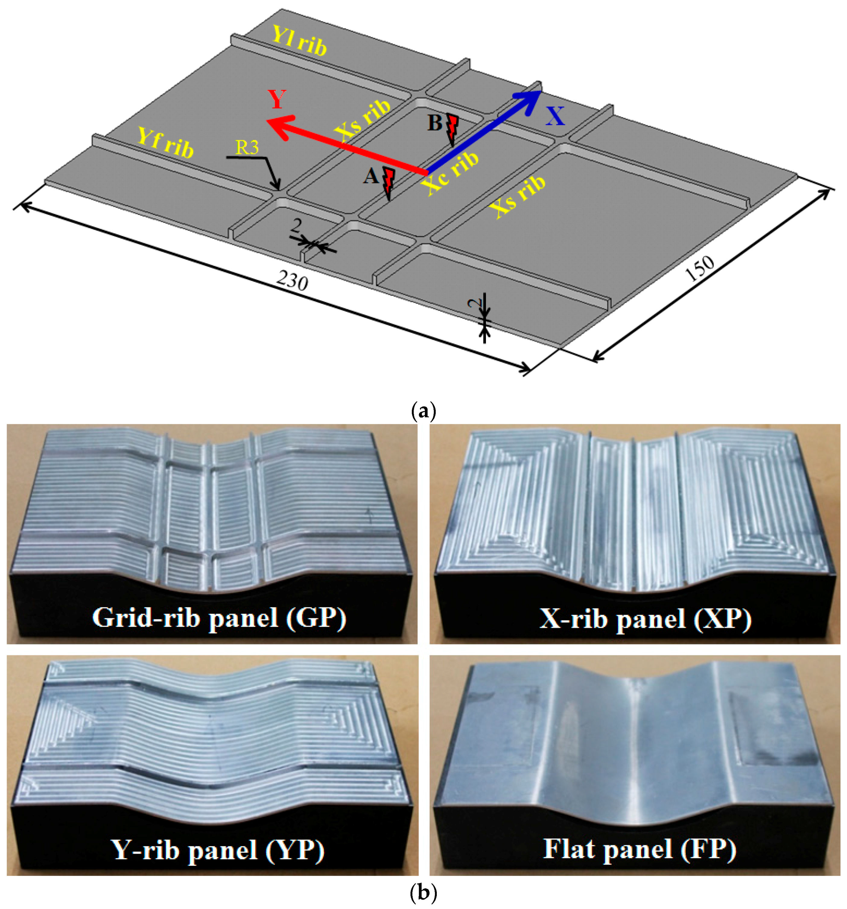
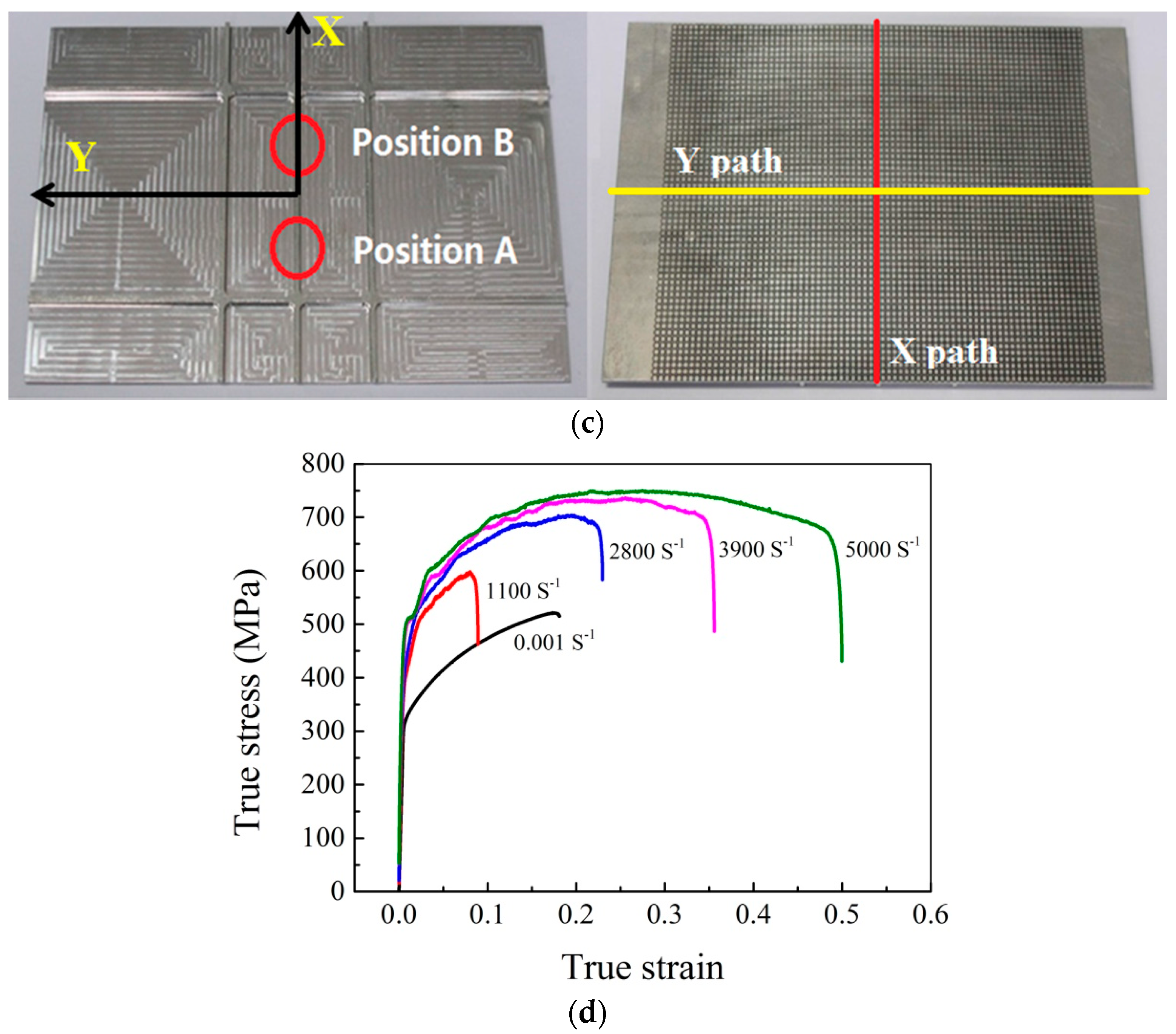
The aim of the deformation process is to form a preformed panel with already existing stiffening ribs into a die with a constant curvature radius. A stiffened panel with grid ribs (Figure 1a), which is obtained by numerical control milling from a flat sheet, is adopted as the workpiece to be formed. For the purpose of comparing, three panels, panel with X direction ribs only (X-rib panel or XP), panel with Y direction ribs only (Y-rib panel or YP) and the flat panel (FP) are studied in which sizes of these three panels are consistent with the grid-rib panel (GP), as shown in Figure 1b. Figure 1c shows the two paths defined in the center of the web. The material of panel is 2A12-T4 aluminum alloy [33], and the material property of the alloy is considered as isotropic in this study. The stress-strain data (Figure 1d) of the alloy are obtained through quasi-static and dynamic experiments, respectively. The dynamic experiments were carried out in the split Hopkinson pressure bar (SHPB) machine at the condition of room temperature to obtain the material properties at high strain rates. The sketch of the die is shown in Figure 2.
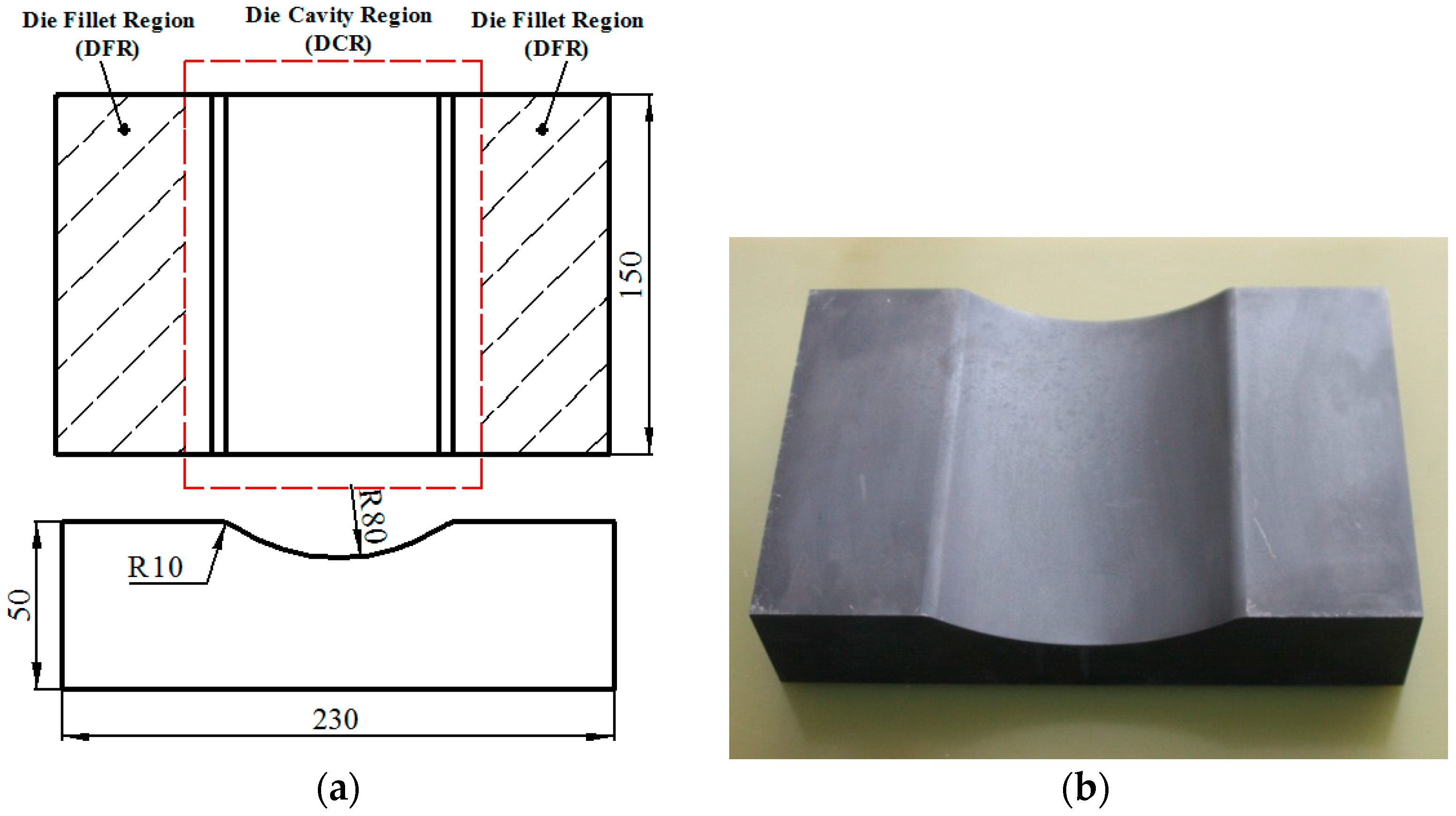
A sequentially coupled FE model between the electromagnetic field and mechanical field with a half of the stiffened panel is shown in Figure 3a. The entire simulation in one discharge forming process is divided to several incremental times steps (1 ms for every step). The electromagnetic forces obtained in the electromagnetic field due to the external load from the coil are as input for the mechanical field. Before the next step analysis, the electromagnetic field is updated according to the deformed configuration in the former step. The cycle continues until the current reduces to zero and then the deformation of the workpiece lasts until the dynamic energy of the workpiece reduces to zero. When the coil moves to another position, the simulation process is identical to the first position.
In order to improve the calculation efficiency, an 1/2 model is established and the infinite flag is set on the infinite surface of Figure 3a. The simulation is performed via the ANSYS V8.1 platform (Ansys, Inc., Pittsburgh, PA, USA), that is, ANSYS/Emag module for the electromagnetic field and LS-DYNA for the mechanical field. The contact type between the workpiece and the die is automatic surface–surface. The wrinkling is not considered in the mechanical model. During the forming process, two discharging positions (position A and B in Figure 1a, corresponding to the center of the coil) are planned along the X axis. The experimental current measured in the coil (Figure 3b) is regarded as the input of the external load of the electromagnetic field in the simulation. The initial d between the coil and the rib is 5 mm.
The semi-finished workpiece is considered to be isotropic, without any residual stress, and the effect of temperature rise on the workpiece is neglected as it is relatively small in this study.
Figure 4 shows the comparison of experimental and simulated forming displacements of the panel along the two paths after discharging in position A and position B, as well as thickness of the web along the two paths at the end. It can be observed from Figure 1a,b that the maximum error in position A is only 6.5% and 9.2% along X path and Y path, respectively, and 5.4% and 7.2% along X and Y direction paths for position B from Figure 1c,d. For the thickness of the web, the maximum error is only 3.1% and 2.1% along X path and Y path from Figure 1c. Figure 4 indicates that the model in the simulation is reliable.
3. Forming Rules of Stiffened Panels during EMIF Process
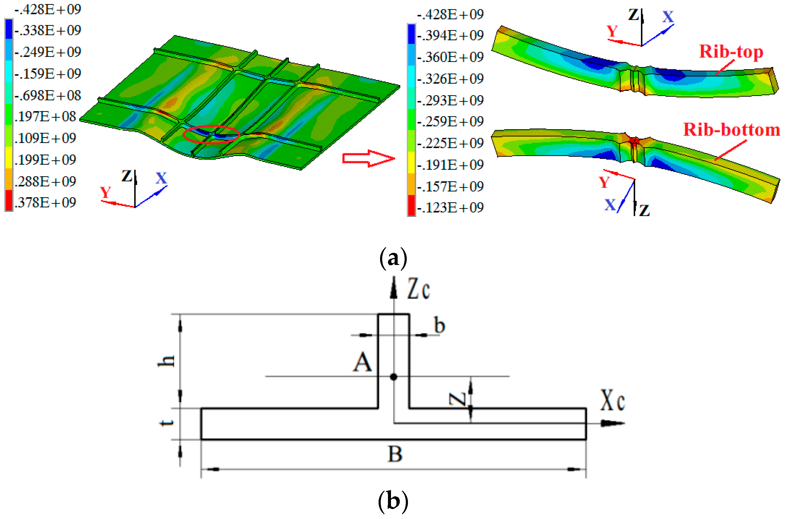
To analyze the forming rules of the stiffened panels in EMIF, forming processes of four panels (Table 1), including three loading passes (two discharges in position A and once in position B), are studied using the FE model established in Section 2. The conditions of these two positions are shown in Table 2. In each pass of forming process, the forming time includes two parts, the current loading time (all equal to 0.45 ms for the three discharges) and the inertial deformation time (0.30 ms, 0.40 ms and 0.40 ms for the three discharges, respectively). That means 0–0.75 ms is the first discharge stage, 0.75–1.60 ms the second discharge stage and 1.60–2.45 ms the third discharge stage. Times of 0.15 ms, 0.90 ms and 1.75 ms, corresponding to the largest forming velocity, are observed as the early stages of each pass, and 0.75 ms, 1.60 ms and 2.45 ms are as the end of each pass.
3.1. Characteristic of Force
Figure 5 shows the distribution and variation of the maximal electromagnetic forces in each discharge pass for the stiffened panel (SP) and the flat panel (FP). In order to compare the force distribution expediently, results for the SP include the ribs and the web, showing 1/2 model only. As shown in Figure 5a,c,e, there exist forces in the ribs and the web simultaneously, and the electromagnetic forces mainly concentrate in the ribs corresponding to the 2/3 coil radius. In the first discharge, from Figure 5a, the maximal force in the rib is about 5 times larger than the force in the web, and about 2 times for the second and third discharge; there are few forces loading in the rib of the longitudinal symmetrical plane. It indicates that the induced eddy current mainly locates in two ribs, that is, the X direction ribs on the two sides of the symmetrical plane, and the Y direction rib below the current position of the coil. Similarly, large electromagnetic forces in the web, as shown in Figure 5a, also distribute correspondingly to the 2/3 coil radius. From Figure 5a,c,e, comparison of the maximal forces in each discharge for the SP shows that the maximal force at the first discharge is greater than that at the third discharge, and the maximal force at the second discharge is the smallest value. This is because the coil is located far away from the panel at the second discharge, and the workpiece near the first discharge position produces a larger deformation than the workpiece near the second discharge position following the previous two discharges. It can also be observed that large forces in the web mainly locate at the free edge. Additionally, as shown in Figure 5, maximal forces in the FP approximate to the SP in the same discharge. Comparisons of the force distribution between the FP and the web of the SP in three discharges demonstrate that existence of the ribs can influence the force distribution, and the forces in the web are divided into different regions by the ribs, which further results in the inhomogeneous distribution of the forces in the web.
Figure 6 shows the forming depth and velocity in Z direction along the X path in order to observe the influence of the electromagnetic forces. Figure 6a shows the forming depth after the three discharges along the observed path. From Figure 4, large electromagnetic forces distributes in the 2/3 coil radius (center in X = −20 mm) when the coil discharges in position A, but the largest forming depth shown in Figure 6a occurs in the free end (X = −75 mm). That is because the free end is subjected to less constraint compared to the largest forces regions, which resulting in easier deformation resistance under the inertial effect. Since the distance between the workpiece and coil increases after the first discharge forming, the discharging energy in the second discharge must be larger than that in the first discharge. Figure 6a indicates that the second discharge in the same position (Position A) is useful to improve the depth. It can be seen from Figure 6b that the forming depth reduces after reaching the maximal value and there is reverse displacement at the positive X free end (region near X = 75 mm). Figure 6c shows that the forming velocity reduces firstly after reaching the maximal value and then reverses at both free ends. In the following analysis of stress distribution, the influence of the reverse deformation at the positive X free end on the stress is discussed.
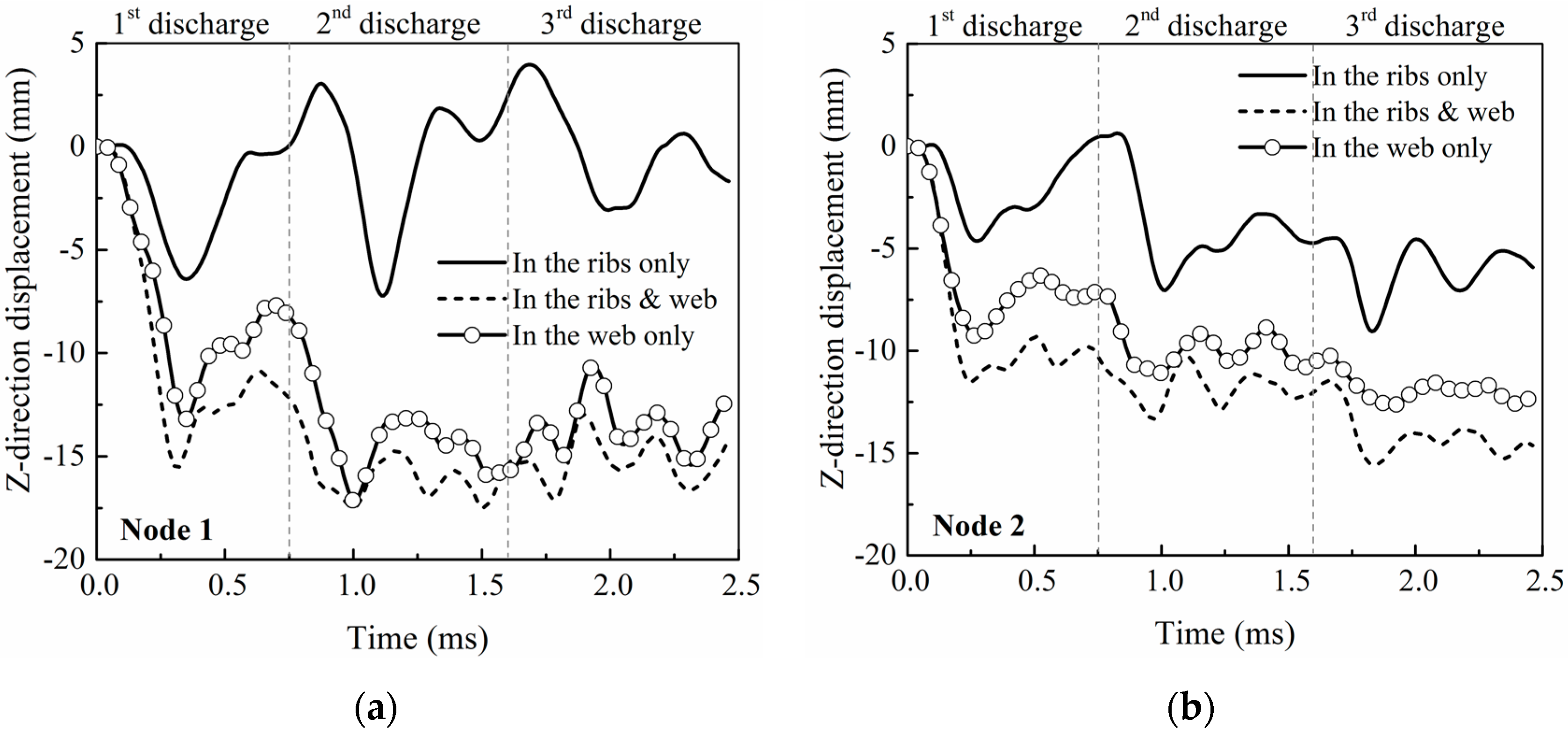
Considering that the electromagnetic forces distributing on the ribs and web simultaneously, it is necessary to distinguish the deformation mechanism of the forces on different regions of the panel. Therefore, a comparison of forming depth of the grid-rib panels in three defined nodes in Figure 7d with three different loading ways is conducted, where the forces are artificially limited to apply on the ribs-only, web-only and the ribs and the web simultaneously. The results are shown in Figure 7. It can be seen from Figure 7 that the forming depth obtained as loading in the ribs-only are significantly less than those in the webs-only and in the ribs and web, and the forming depths in the web-only are more closer to the real displacement (loading in the ribs and web). The result in Figure 7 indicates that the deformation of the stiffened panel is mainly affected by the forces on the web, not the ribs, when the electromagnetic forces applying on the ribs and web at the same time. That is because the area of the web under electromagnetic forces is larger than that of the rib, as well as the effect of the improved structural stiffness due to the ribs, which makes it difficult to deform under the forces in the ribs only.
3.2. Evolution of Stress
In this section, study on stress evolution of the grid-stiffened panels is conducted, and the shear stress is neglected since it is obviously smaller than the normal stress from the simulated results. Figure 8 shows the stress components of GP during the first discharging. It can be seen that the distribution of stress component is non-uniform and related to the direction of the ribs. X direction ribs are mainly under the application of uniaxial stress, the stress component σx. Since deformation begins in the electromagnetic force regions (about 2/3 coil radius), large tensile stress in Figure 8a locates in the Xc rib, corresponding to the region under the coil center, and large compressive stress concentrates in the regions corresponding to large electromagnetic forces. Similarly, Y direction ribs are also mainly under the application of uniaxial stress, the stress component σy. With the tensile effect in the die fillet region (DFR), materials between the two X direction ribs are subject to compressive stress. For the web, it is also mostly subject to biaxial-tensile plane stress (σx and σy), except for the three-direction stress at t = 139 μs in Figure 8b, approximately when the electromagnetic force reaches the peak value; large stress mainly concentrates in the DFR. There is compressive stress, from Figure 8c, at the bottom of the web corresponding to the Yl rib due to the reverse bend of the web in the free end shown in Figure 8a and the reverse bend disappears in the inertial stage at t = 612 μs in Figure 8d. From Figure 8d, the deformation of the panel continues under the inertial effect after the discharge time (t > 450 μs), indicating that the inertial deformation has influence on the stress distribution of the panel.
As time increases, stress state of the Y direction ribs keeps stable with tensile stress in the DFR and compressive stress in the region of the Yf rib between the two X direction ribs, while the stress state of the X direction ribs changes between tensile and compressive stress. The main reasons for the change of the X direction stress state are: the effect of the electromagnetic forces (including region and direction) at the early stage and the inertial effect at the later stage. In addition, the reverse bend in the free end far from the coil can also affects the local stress distribution.
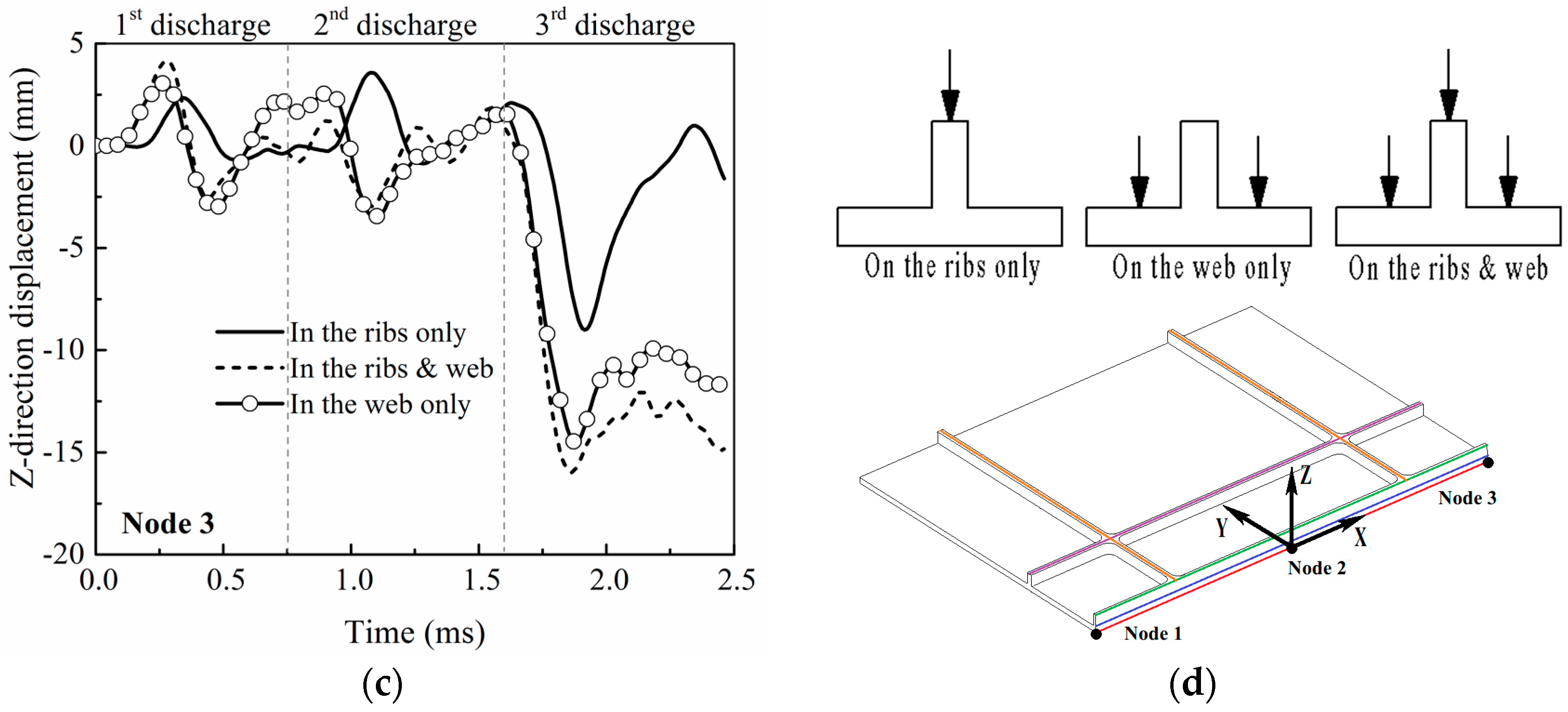
Neglecting the side bend (very weak) in Figure 8, the Yf rib can be regarded as in-plane bend during the first position forming. Here, the Y direction stress in the Yf rib is exhibited in Figure 9a. As shown in Figure 9a, the observed region is under the effect of compressive stress at the top and bottom of the rib, completely different stress directions from a typical in-plane bend process where the inner side subjects to compressive stress and outer tensile stress. The position of the stress neutral layer may helpful to explain this difference. The Yf rib and its adjacent web can be considered as a single inverted T-structure from the cross-section in Figure 9b, therefore, the initial neutral layer position during the elastic deformation stage of the T structure can be calculated. Considering the symmetry, the distance between the neutral layer and the half depth of the web is shown as Equation (15),
where B, b, h and t means the effective width of the web, the width of the rib, the height of the rib and the height of the web, respectively. For a given panel, parameters b, h and t are constant, but the effective width of the web B changes with deformation progress. Hence, the stress neutral layer may locates in varied region according to the change of B, as listed in Equation (16),
The neutral stress layer will move with the bend deformation. From Equation (15), it can be concluded that the top of the rib locates in the inner side (subjected to compressive stress) during the bend and the bottom of the web locates in the outer side (subjected to tensile stress). However, the direction of the Y-direction stress component of the rib near the rib-root depends on the bend radius and the width B. For example, when the width B is small enough, that is B < b (h/t)2, the neutral layer will locate in the rib, and the entire rib will be under the effect of compressive stress, just as shown in Figure 8 and Figure 9a.
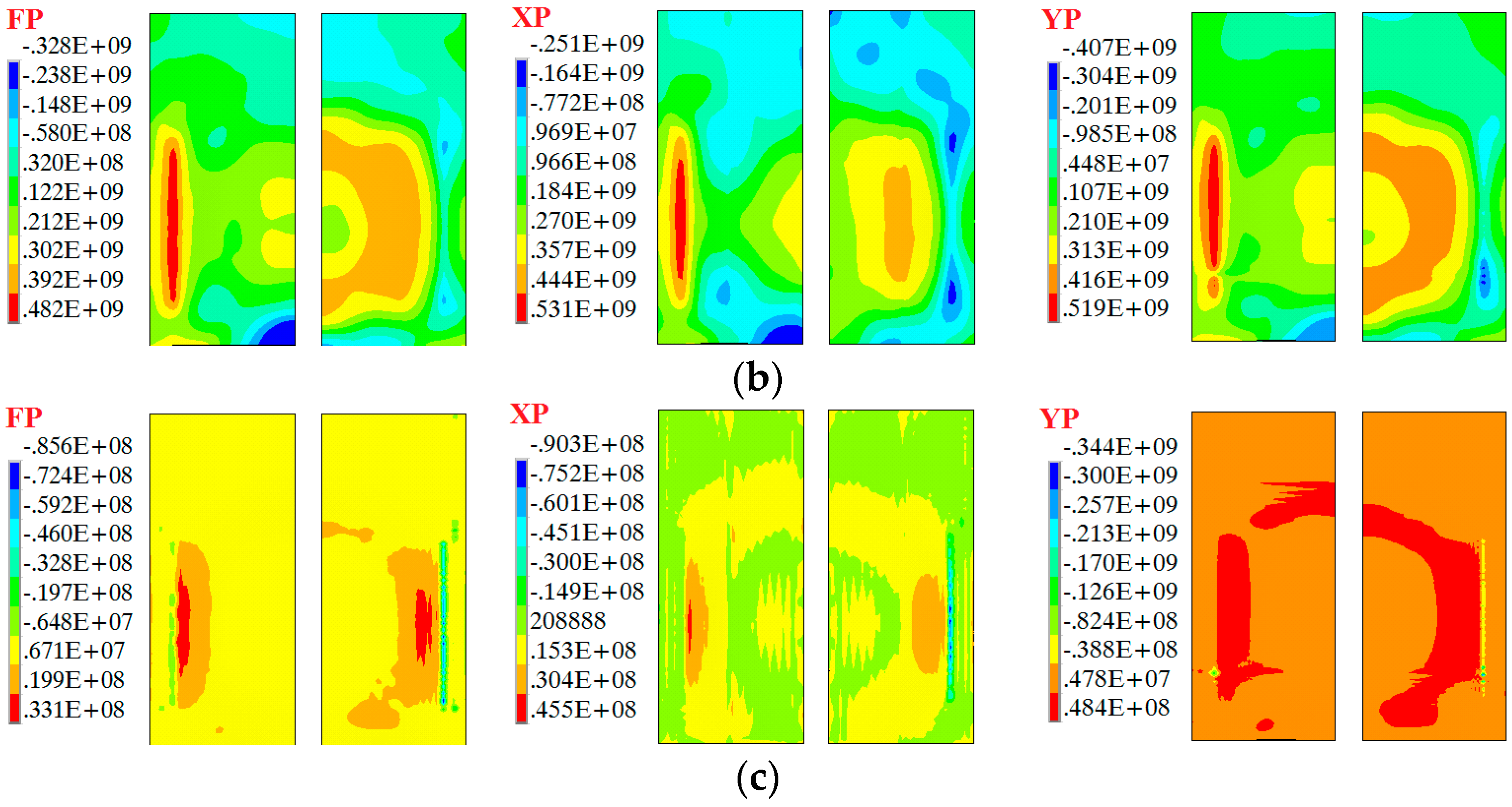
Figure 10 shows the equivalent von Mises stress distribution of the four panels during three passes forming. From Figure 10, large equivalent stress of the fours panels in the early stage of the first discharge (t = 0.15 ms) mainly distributes in the DFR of the web, including the ribs in the DFR. That means the dangerous region of EMF for the stiffened panels begins in the identical region to the traditional stamping process. However, in the second discharge, large stress also concentrates in the X direction ribs in the DCR (Figure 10b,d) due to the drag and drop effect. That indicates that during EMIF of stiffened panels, when there are X direction ribs, dangerous stress may also occur in the X direction ribs. Therefore, a reasonable discharging position and discharging energy in position A should be considered in the design of the process parameters.
In addition, under the influence of the two direction ribs, the maximal stress values of GP are larger than those of YP.
Figure 11 illustrates the residual stress distribution of the four panels. It can be seen that stress values of the Y-rib panel and the grid-rib panel are greater than the other two panels. Obvious stress concentrations are not found in the FP (Figure 11a) and XP (Figure 11b). However, there are stress concentration at the rib-top for the YP (Figure 11c) and the GP (Figure 11d). That means the ribs in Y direction result in the increase of residual stress and affect the forming non-uniform of the EMIF process.
3.3. Evolution of Strain
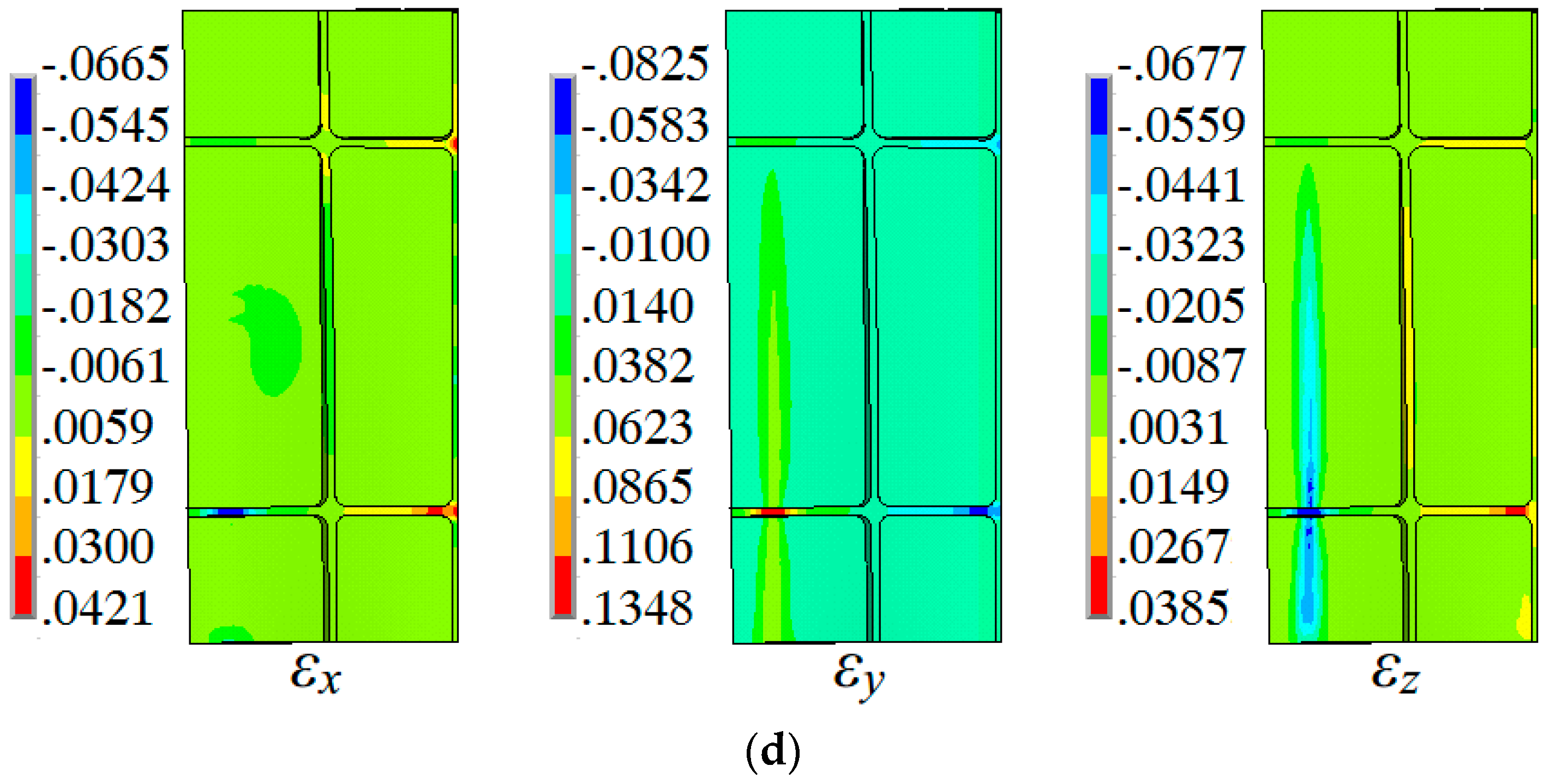
Figure 12 shows the distributions of three normal strain components (εx, εy and εz) for the grid-rib panel in the deformation region. From Figure 12, large strain mainly concentrates in the web of the DFR and the Yf rib and the maximal tensile strain occurs in the Yf rib of the DFR. Affected by the normal stress distribution, the Yf rib is under the application of three-directional strain: for the DFR, tensile strain in the Y direction and compressive strain in the other two directions; for the DCR, with opposite strain state, compressive strain in the Y direction and tensile strain in the other two directions. The web of the whole deformation region is within plane strain state, tensile strain in the Y direction and compressive strain in the Z direction. From Figure 12, strain of the web in the DCR is no more than 2.5% during the first position forming, which means the deformation mainly occurs in the ribs. From Figure 12, it can be found that extension deformation mainly locates in the DFR, which means thinning occurs easily in this region. In addition, large compression stain in the Y direction of the Yf or Yl ribs means wrinkling occurs easily in these ribs.
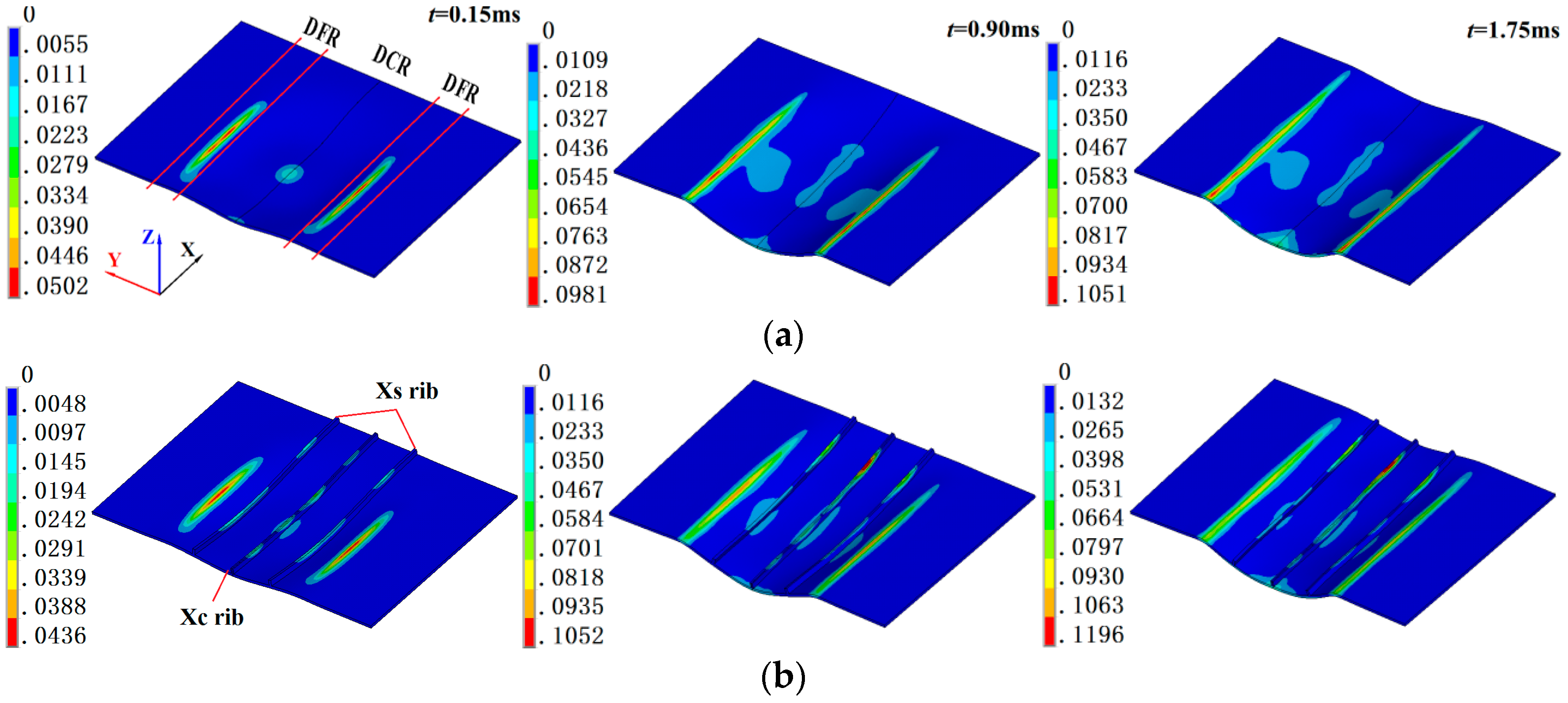
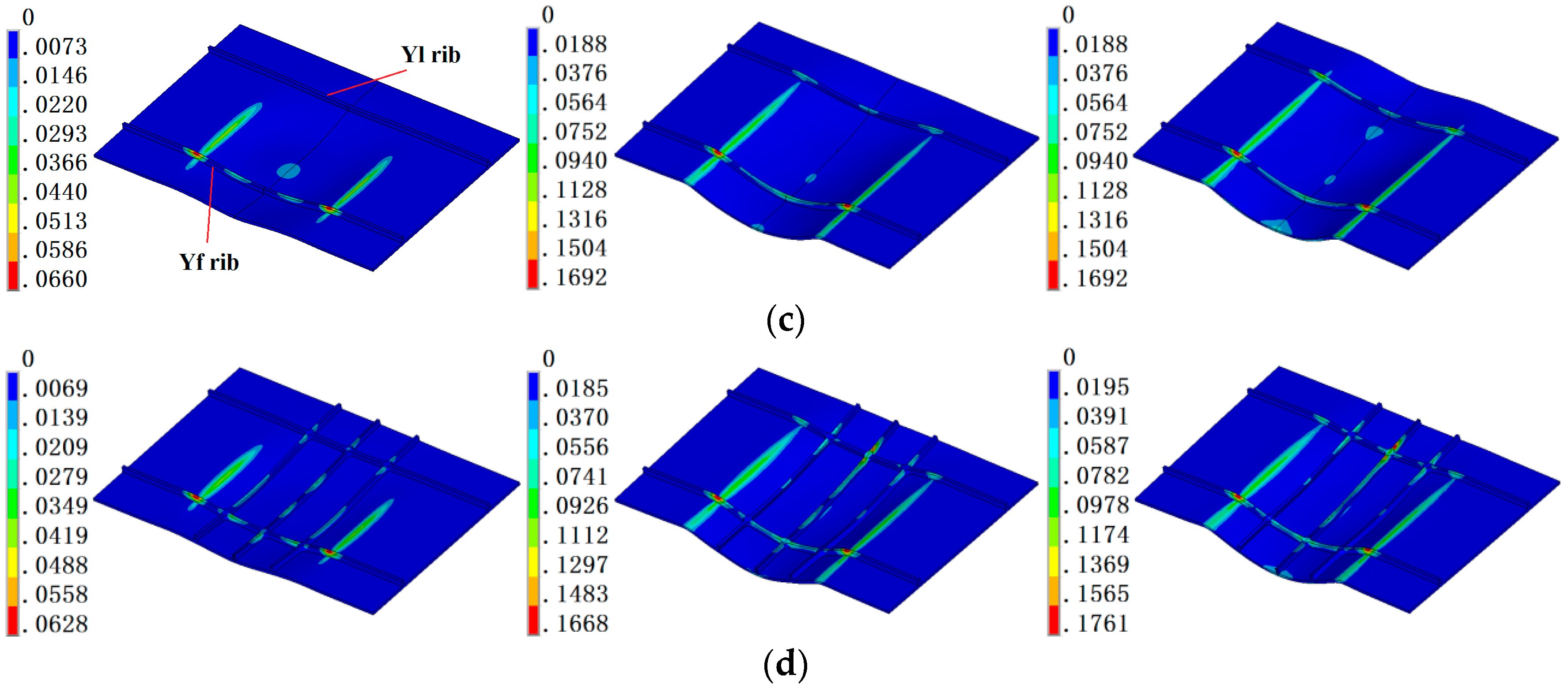
In the impulse forming process, the workpiece enters the plastic deformation stage in a very short time, it is important to obtain the evolution rules of the plastic strain. The equivalent plastic strain component distributions of four panels at three discharging times (t = 0.15 ms, 0.90 ms and 1.75 ms) are shown in Figure 13. From Figure 13a, large equivalent plastic strain for FP mainly distributes in the web of the DFR and increases significantly in the first two discharges and increase slowly in the third discharge. In the die cavity region (DCR), the plastic strain is very small, no more than 2.4%. From Figure 13b, in the DCR, large equivalent plastic of XP concentrates at the top of the Xc rib since t = 0.90 ms. From Figure 13c, large equivalent plastic strain for YP mainly distributes at the top of the two ribs in the DCR and the web in the DFR. For the grid-rib panel, from Figure 13d, plastic strain mainly distributes at the top of the two Y direction ribs and the top of the Xc rib in the DCR. The maximal strain value for the top of the X direction center-rib is larger than that at the top of the two Y direction ribs.
The equivalent strain distribution of the three panels with ribs in Figure 13 shows that the large equivalent plastic strain in the DCR mainly distributes in the ribs, and plastic strain in the web is very small. It means deformation of the panel with ribs is driven by the ribs, and neutral layer mainly distributes in the ribs. That deformation mode increases the inconsistency between the ribs and the web. In addition, for FP and XP, plastic strain in the DCR is obviously smaller than the other two panels due to the deformation feature is extension deformation in the Y direction.
3.4. Influence of Rib Configuration on the Web
Since the existence of the ribs will affect the deformation progress for the varied panels. It is necessary to study the influence of rib with different directions on the deformation during the EMIF process. In this section, the influences of the ribs on the webs are discussed.
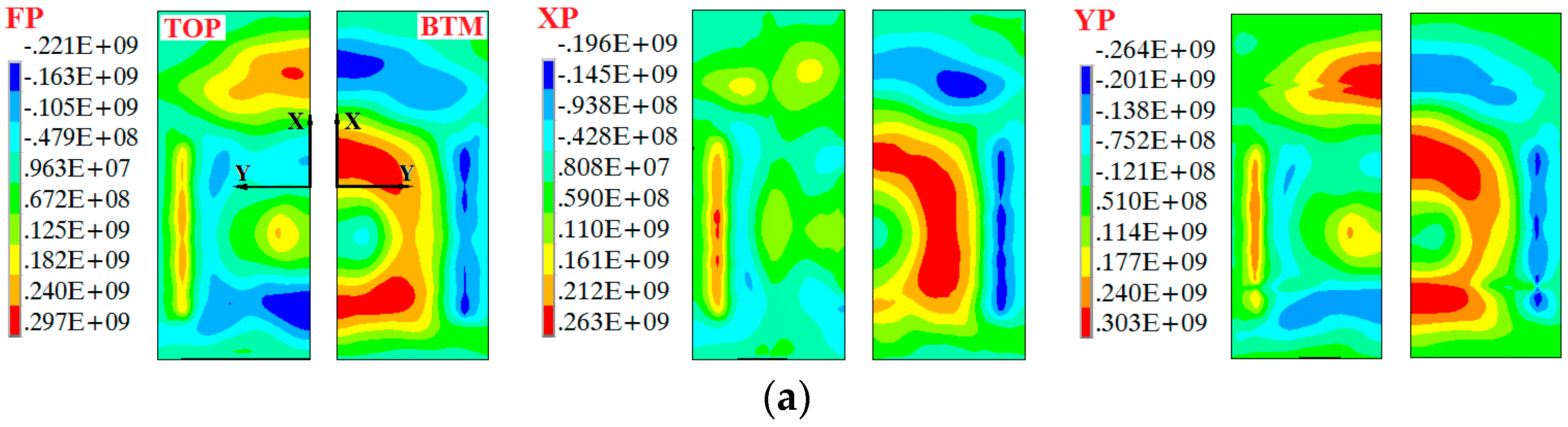
Figure 14 shows the distribution of the normal stress components on the webs of the three panels during the first position forming. The observed time t = 139 μs is chosen because the stress component σy of the grid-rib panel (Figure 8) gets the maximal value during the entire process. From Figure 14a, for stress component σx of FP, different from GP, large stress also concentrates in the region near the −X free end, corresponding to the Yf rib of GP, subjected to opposite stress direction to the region near the +X free end. It indicates that the Yf rib changes the stress concentration in that region. Moreover, large stress regions at the bottom focus in the region near the symmetric plane of the Y axis. For XP, its stress distribution and maximal stress values are in accordance with GP. The stress distribution of YP is similar to that of FP and there are also four large stress regions. The obvious difference between YP and the other three panels is the maximal stress values of the YP are larger. Comparison of maximal stress values shows that YP with the largest values and XP the smallest values, and stress concentration region corresponding to the Yf rib indicates that the existence of Y direction ribs enhance the deformation difficulty and increase the stress level of the X direction component. For the Y direction component σy in Figure 14b, the maximal tensile stress value of XP is larger than those of YP and GP, and FP is the smallest. It can be explained that the extension of the materials along the Y direction is hampered by the X direction ribs. The maximal compressive stress values for YP and GP in the DFR at the bottom of the web, are larger than those of the other two panels is resulted from the enhancement of structure stiffness in the DFR. The distribution of the Z direction component σz for the four panels, from Figure 14c, shows that the stress values in this direction for GP and YP are significantly larger than those of FP and XP, and can be ignored for the latter two panels without Y direction ribs. Both the compressive stress concentration regions for GP and YP locate in the DFR, the region with Y direction ribs. It further expresses that the Z direction component σz should be considered if there are Y direction ribs (e.g., YP and GP).
4. Conclusions
The forming rules of the stiffened panels with gird ribs during the EMIF process is revealed via analyzing the evolution of the forming depth, stress and strain. The main conclusions are as follows:
- (1)
- The forming depth of the stiffened panels is largely due to the forces on the web, not the ribs, due to the fact that the area and the structural stiffness of the web is larger than that of the ribs, although the electromagnetic forces are applied on both the ribs and the web and mainly concentrate on the ribs.
- (2)
- The ribs are subjected to the uniaxial stress parallel to the rib directions, and the web is subjected to plane stress in the die cavity region and three-directional stress in the die fillet region. There are both compressive stresses along the rib direction at the top and bottom of the Y-direction ribs because the stress neutral layer locates in the web. Reasonable parameters should be designed carefully if there are X direction ribs due to large stress which also concentrates in these ribs.
- (3)
- The Y direction ribs are subjected to three-directional strain with tensile deformation in the die fillet region and compressive deformation in the die cavity region. Large strain in the web concentrates in the die fillet region with plane strain. Large tensile plastic deformation in the die fillet region inclines to thin easily, and compressive strain in the Y-direction ribs of the die cavity region easily inclines to wrinkling.
Acknowledgments
This work is supported by the National Science Fund for Distinguished Young Scholars of China (51625505), the Key Program Project of the Joint Fund of Astronomy and National Science Foundation of China (Project U1537203) and the National Key Basic Research Program of China (973 Program, Grant No. 2011CB012804).
Author Contributions
The first author Jinqiang Tan performed the simulation and relative experiments, and wrote this article under the guidance of the corresponding author Mei Zhan; Pengfei Gao and Hongwei Li assisted in performing data analysis and interpreting part of the results.
Conflicts of Interest
The authors declare no conflict of interest.
References
- Pettit, R.G.; Wang, J.J.; Toh, C. Validated Feasibility Study of Integrally Stiffened Metallic Fuselage Panels for Reducing Manufacturing Costs; NASA/CR-2000-209342; Boeing Commercial Airplane Group: Seattle, WA, USA, 2000. [Google Scholar]
- Munroe, J.; Wilkins, K.; Gruber, M. Integral Airframe Structures (IAS)—Validated Feasibility Study of Integrally Stiffened Metallic Fuselage Panels for Reducing Manufacturing Costs; NASA/CR-2000-209337; Boeing Commercial Airplane Group: Seattle, WA, USA, 2000. [Google Scholar]
- Gariépy, A.; Miao, H.; Lévesque, M. Peen Forming. Compr. Mater. Process. 2014, 3, 295–329. [Google Scholar]
- Miao, H.Y.; Demers, D.; Larose, S.; Perron, C.; Levesque, M. Experimental study of shot peening and stress peen forming. J. Mater. Proc. Technol. 2010, 210, 2089–2102. [Google Scholar] [CrossRef]
- Zhan, L.H.; Lin, J.G.; Dean, T.A. A review of the development of creep age forming: Experimentation, modeling and applications. Int. J. Mach. Tool. Manuf. 2011, 51, 1–17. [Google Scholar] [CrossRef]
- Yan, Y.; Wang, H.B.; Wan, M. Prediction of fracture in press bend forming of aluminum alloy. Comput. Mater. Sci. 2011, 50, 2232–2244. [Google Scholar]
- Psyk, V.; Risch, D.; Kinsey, B.L.; Tekkaya, A.E.; Kleiner, M. Electromagnetic forming—A review. J. Mater. Proc. Technol. 2011, 211, 787–829. [Google Scholar] [CrossRef]
- Daehn, G.S. High velocity metal forming. In ASM Handbook Volume 14B: Metalworking: Sheet Forming; ASM International: Columbus, OH, USA, 2006; pp. 405–418. [Google Scholar]
- Woodward, S.; Weddeling, C.; Daehn, G.; Psyk, V.; Carson, B.; Tekkaya, A.E. Agile production of sheet metal aviation components using disposable electromagnetic actuators. In Proceedings of the 4th International Conference on High Speed Forming—ICHSF 2010, Columbus, OH, USA, 9–10 March 2010. [Google Scholar]
- Eguia, I.; Mangas, A.; Iturbe, R.; Gutiérrez, M.A. Electromagnetic forming of longitudinal strengthening ribs in roll formed automotive profiles. In Proceedings of the 4th International Conference on High Speed Forming—ICHSF 2010, Columbus, OH, USA, 9–10 March 2010. [Google Scholar]
- Psyk, V.; Kurka, P.; Kimme, S.; Werner, M.; Landgrebe, D.; Ebert, A.; Schwarzendahl, M. Structuring by electromagnetic forming and by forming with an elastomer punch as a tool for component optimisation regarding mechanical stiffness and acoustic performance. Manuf. Rev. 2015, 2, 23. [Google Scholar] [CrossRef]
- El-Azab, A.; Garnich, M.; Kapoor, A. Modeling of the electromagnetic forming of sheet metals: State-of-the-art and future needs. J. Mater. Proc. Technol. 2003, 142, 744–754. [Google Scholar] [CrossRef]
- Oliveira, D.A.; Worswick, M.J.; Finn, M.; Newman, D. Electromagnetic forming of aluminum alloy sheet: Free-form and cavity fill experiments and model. J. Mater. Proc. Technol. 2005, 170, 350–362. [Google Scholar] [CrossRef]
- Imbert, J.; Worswick, M. Reduction of a pre-formed radius in aluminum sheet using electromagnetic and conventional forming. J. Mater. Proc. Technol. 2012, 212, 1963–1972. [Google Scholar] [CrossRef]
- Lai, Z.P.; Cao, Q.L.; Han, X.T.; Liu, N.; Li, X.X.; Huang, Y.J.; Chen, M.; Cai, H.; Wang, G.D.; Liu, L.Y.; et al. A comprehensive electromagnetic forming approach for large sheet metal forming. In Proceedings of the International Conference on the Technology of Plasticity (ICTP 2017), Cambridge, UK, 17–22 September 2017. [Google Scholar]
- Okoye, C.N.; Jiang, J.H.; Hu, Z.D. Application of electromagnetic-assisted stamping (EMAS) technology in incremental forming. Int. J. Mach. Tools Manuf. 2006, 46, 1248–1252. [Google Scholar] [CrossRef]
- Shang, J.H.; Daehn, G.S. Electromagnetically assisted sheet metal stamping. J. Mater. Proc. Technol. 2011, 211, 868–874. [Google Scholar] [CrossRef]
- Jeswiet, J.; Geiger, M.; Engel, U.; Kleiner, M.; Schikorra, M.; Duflou, J.; Neugebauer, R.; Bariani, P.; Bruschi, S. Metal forming progress since 2000. CIRP J. Manuf. Sci. Technol. 2008, 1, 2–17. [Google Scholar] [CrossRef]
- Cui, X.H.; Mo, J.H.; Li, J.J.; Zhao, J.; Xiao, S.J. Produce a large aluminum alloy sheet metal using electromagnetic-incremental (EM-IF) forming method: Experiment and Numerical simulation. In Proceedings of the 5th International Conference on High Speed Forming, Dortmund, Germany, 24–26 April 2012; pp. 59–70. [Google Scholar]
- Cui, X.H.; Mo, J.H.; Li, J.J.; Zhao, J.; Zhu, Y.; Huang, L.; Li, Z.W.; Zhong, K. Electromagnetic incremental forming (EMIF): A novel aluminum alloy sheet and tube forming technology. J. Mater. Proc. Technol. 2014, 214, 409–427. [Google Scholar] [CrossRef]
- Cui, X.H.; Mo, J.H.; Li, J.J.; Xiao, X.T.; Zhou, B.; Fang, J.X. Large-scale sheet deformation process by electromagnetic incremental forming combined with stretch forming. J. Mater. Proc. Technol. 2016, 237, 139–154. [Google Scholar] [CrossRef]
- Oliveira, D.A.; Worswick, M.J. Electromagnetic forming of aluminum alloy sheet. J. Phys. IV France 2003, 110, 293–298. [Google Scholar] [CrossRef]
- Yu, H.P.; Li, C.F.; Deng, J.H. Sequential coupling simulation for electromagnetic mechanical tube compression by finite element analysis. J. Mater. Proc. Technol. 2009, 209, 707–713. [Google Scholar]
- Fenton, G.K.; Daehn, G.S. Modeling of electromagnetically formed sheet metal. J. Mater. Proc. Technol. 1998, 75, 6–16. [Google Scholar] [CrossRef]
- Unger, J.; Stiemer, M.; Svendsen, B.; Blum, H. Multifield modeling of electromagnetic metal forming processes. J. Mater. Proc. Technol. 2006, 177, 270–273. [Google Scholar] [CrossRef]
- Cui, X.H.; Li, J.J.; Mo, J.H.; Fang, J.X.; Zhu, Y.T.; Zhong, K. Investigation of large sheet deformation process in electromagnetic incremental forming. Mater. Des. 2015, 76, 86–96. [Google Scholar] [CrossRef]
- Tan, J.Q.; Zhan, M.; Liu, S. Guideline for forming stiffened panels by using the electromagnetic forces. Metals 2016, 6, 267. [Google Scholar] [CrossRef]
- Cao, Q.L.; Han, X.T.; Lai, Z.P.; Xiong, Q.; Zhang, X.; Chen, Q.; Xiao, H.X.; Li, L. Analysis and reduction of coil temperature rise in electromagnetic forming. J. Mater. Proc. Technol. 2015, 225, 185–194. [Google Scholar] [CrossRef]
- Rodríguez, A.A.; Valli, A. Eddy Current Approximation of Maxwell Equations: Theory, Algorithms and Applications; Springer: Milan, UK, 2010. [Google Scholar]
- Biro, O.; Preis, K. On the Use of the Magnetic Vector Potential in the Finite Element Analysis of Three-Dimensional Eddy Currents. IEEE Trans. Magn. 1989, 25, 3145–3159. [Google Scholar] [CrossRef]
- Hallquist, J.O. LS-DYNA Theoretical Manual; Livermore Software Technology Corporation: Livermore, CA, USA, 1998. [Google Scholar]
- Pao, Y.H. Electromagnetic force in deformable continua. In Mechanics Today; Nemat-Nasser, S., Ed.; Pergamon Press: Oxford, UK, 1978. [Google Scholar]
- International Organization for Standardization. ISO 209: Aluminium and Aluminum Alloy—Chemical Composition; International Organization for Standardization (ISO): Geneva, Switzerland, 2007. [Google Scholar]
Figure 1.
The information of the panels: (a) sizes (mm) and different ribs; (b) deformed panels with different rib-styles; (c) the defined paths of the web; and (d) the stress-strain data of 2A12-T4 aluminum alloy.
Figure 1.
The information of the panels: (a) sizes (mm) and different ribs; (b) deformed panels with different rib-styles; (c) the defined paths of the web; and (d) the stress-strain data of 2A12-T4 aluminum alloy.


Figure 2.
The sketch of the die: (a) sizes (mm); and (b) experimental photo.

Figure 3.
The finite element (FE) model for the stiffened panels during electromagnetic incremental forming (EMIF) process: (a) the meshed mode; and (b) the input experimental coil-current at different discharging voltages.
Figure 3.
The finite element (FE) model for the stiffened panels during electromagnetic incremental forming (EMIF) process: (a) the meshed mode; and (b) the input experimental coil-current at different discharging voltages.

Figure 4.
Comparison between experimental and simulated results: (a,b) Z-displacement in position A along X and Y path; (c,d) Z-displacement in position B along X and Y path; (e,f) web thickness along X and (f) Y path.
Figure 4.
Comparison between experimental and simulated results: (a,b) Z-displacement in position A along X and Y path; (c,d) Z-displacement in position B along X and Y path; (e,f) web thickness along X and (f) Y path.
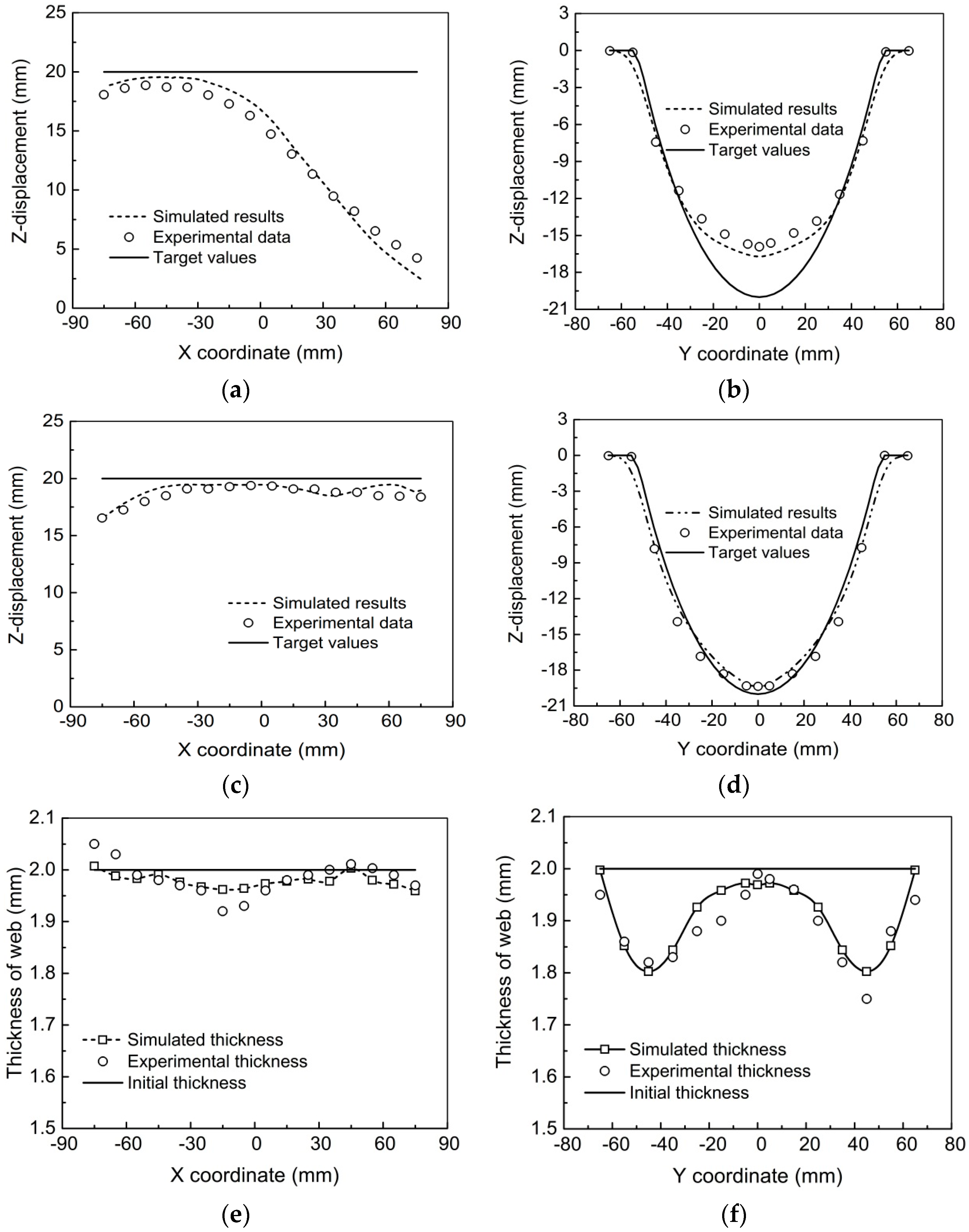
Figure 5.
Electromagnetic force (N) distribution in the SP (Left, ribs and web) and FP (Right) during EMF in the first discharge (a,b), second discharge (c,d) and third discharge (e,f).
Figure 5.
Electromagnetic force (N) distribution in the SP (Left, ribs and web) and FP (Right) during EMF in the first discharge (a,b), second discharge (c,d) and third discharge (e,f).
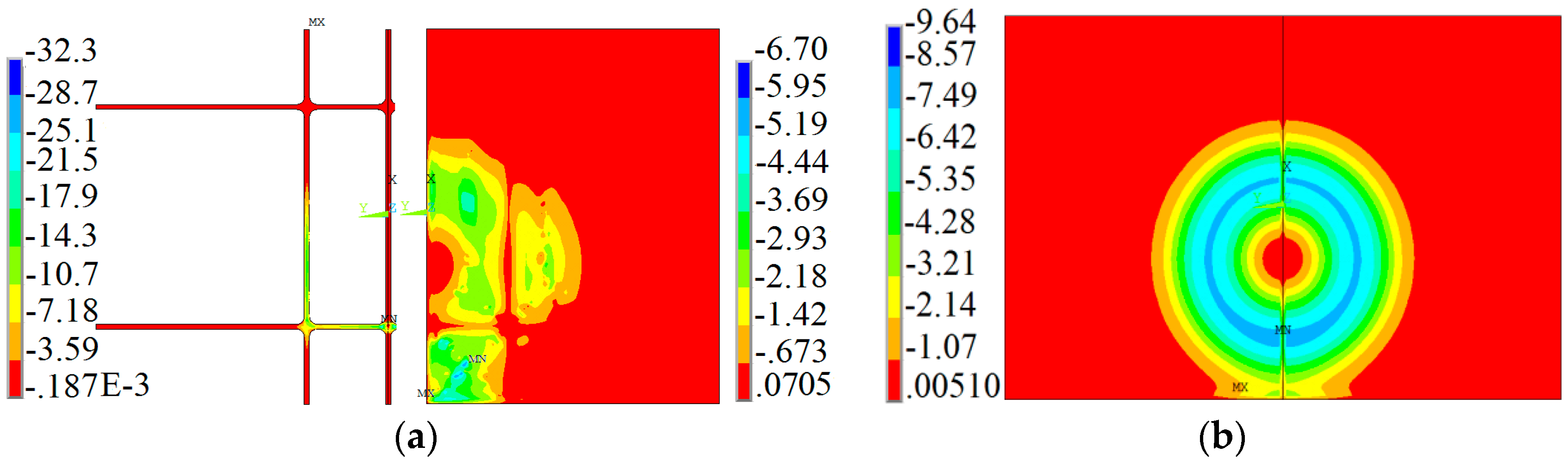
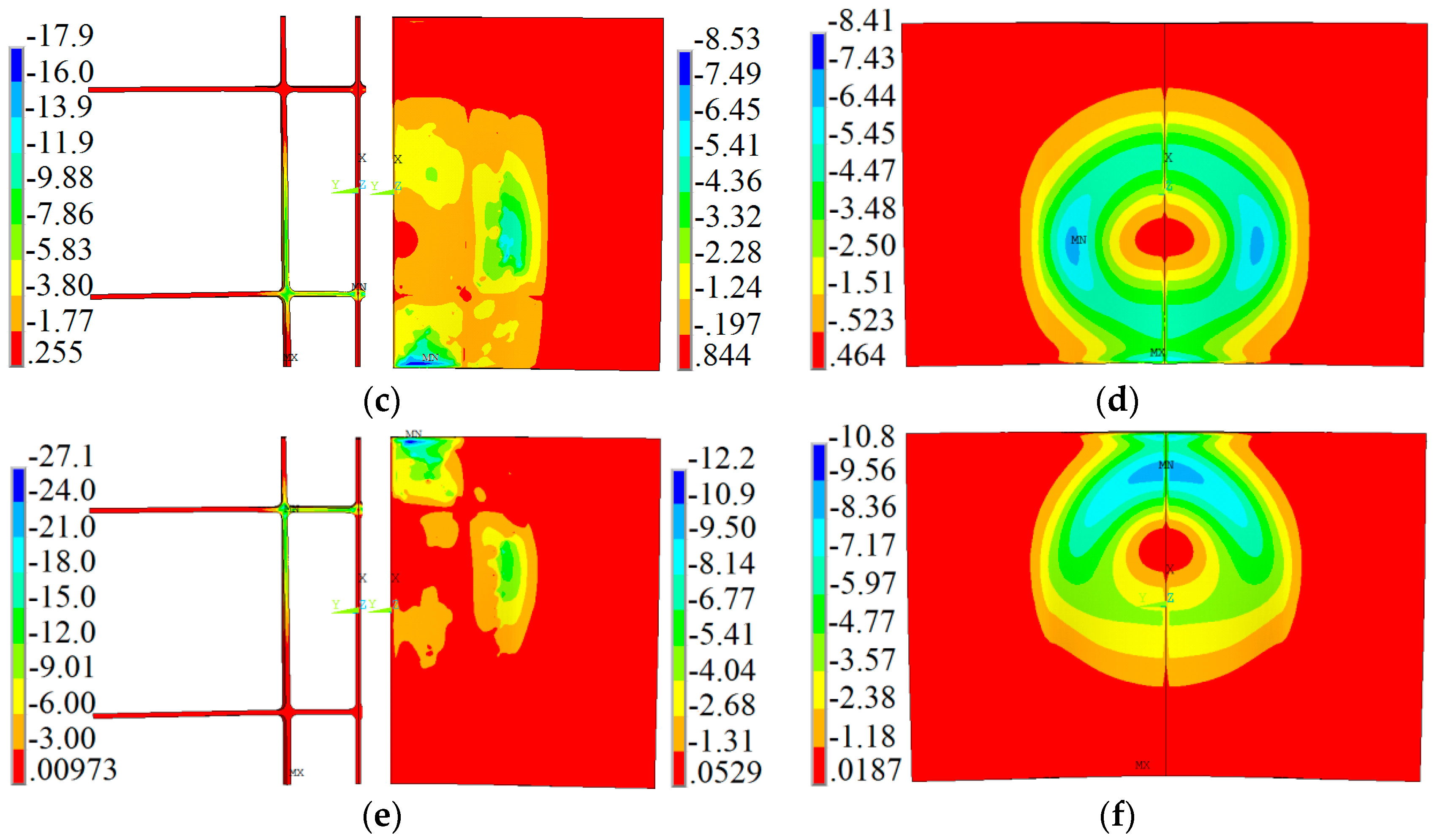
Figure 6.
Z-direction results. (a) Z-direction displacement after three discharges along the X path; (b) Z-direction velocity and (c) of GP along the X path in position A.
Figure 6.
Z-direction results. (a) Z-direction displacement after three discharges along the X path; (b) Z-direction velocity and (c) of GP along the X path in position A.

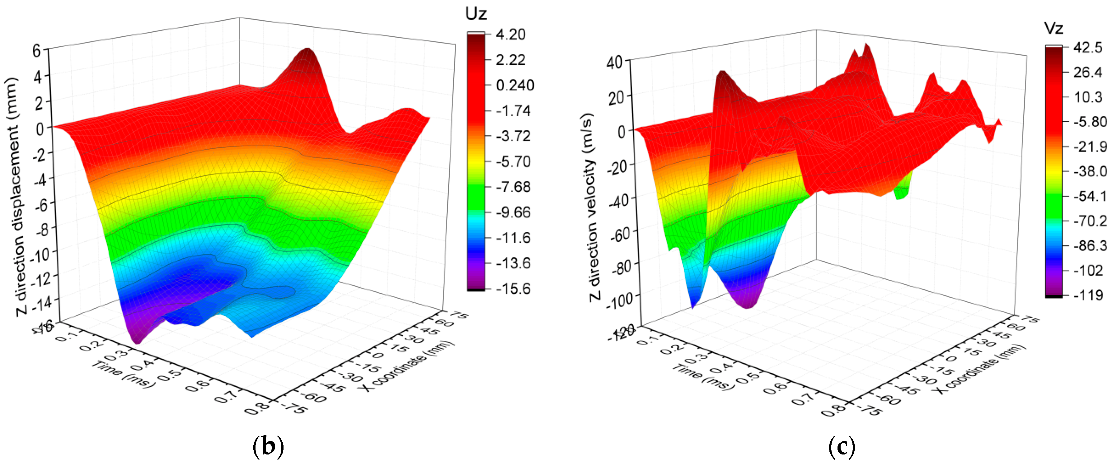
Figure 7.
Z-direction displacement with forces loading in different positions at (a) Node1; (b) Node 2; (c) Node 3; (d) sketch.
Figure 7.
Z-direction displacement with forces loading in different positions at (a) Node1; (b) Node 2; (c) Node 3; (d) sketch.


Figure 8.
Normal stress components (Pa) of GP in position A: (a) at t = 51 μs; (b) at t = 139 μs; (c) at t = 394 μs; and (d) at t = 612 μs.
Figure 8.
Normal stress components (Pa) of GP in position A: (a) at t = 51 μs; (b) at t = 139 μs; (c) at t = 394 μs; and (d) at t = 612 μs.
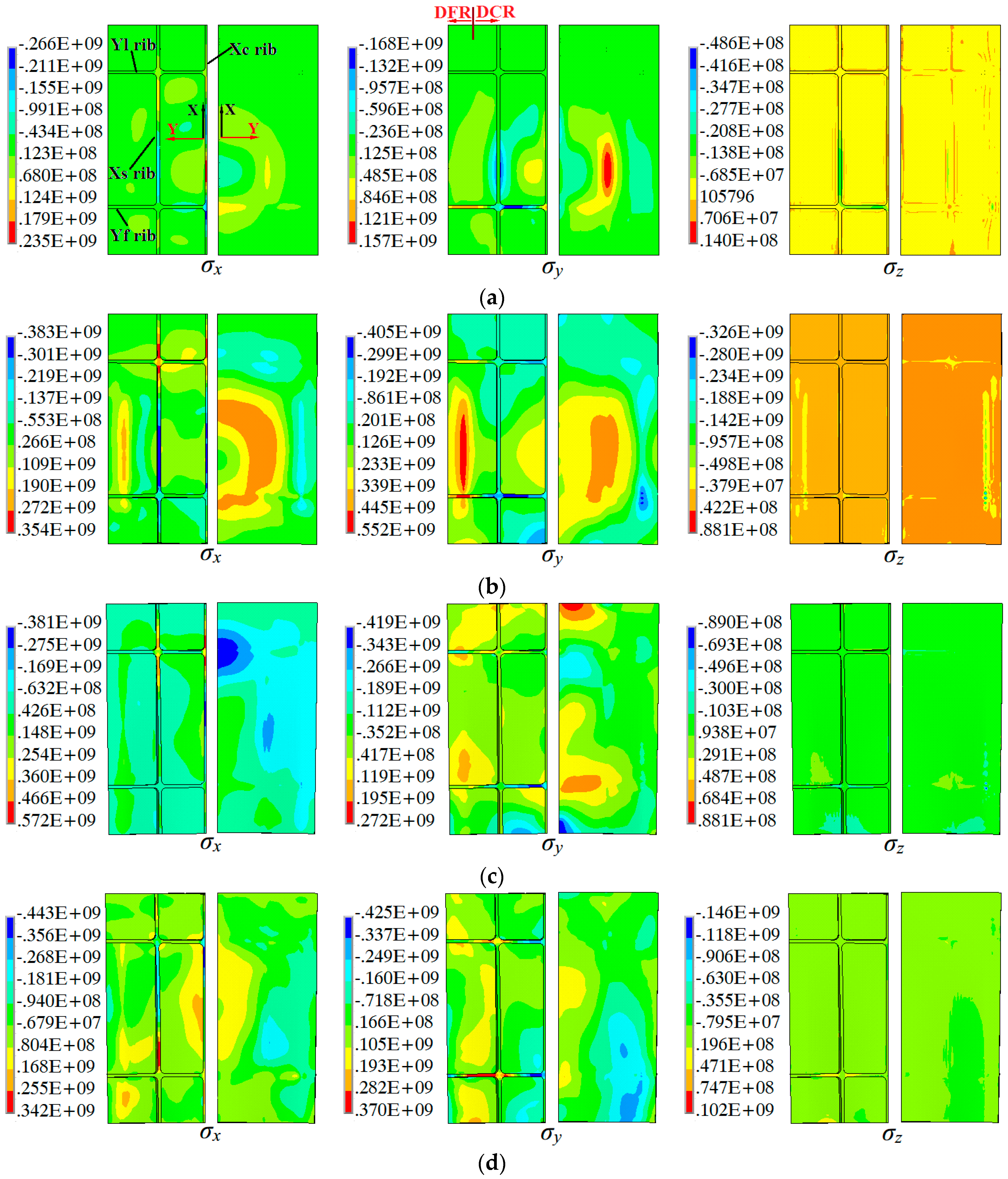
Figure 9.
The Y-direction stress component (Pa) in the center of the Yf rib (a) and the inverted T-structure (b).
Figure 9.
The Y-direction stress component (Pa) in the center of the Yf rib (a) and the inverted T-structure (b).

Figure 10.
Equivalent von Mises stress distribution of four panels in the early stage of each discharge (Pa): (a) FP; (b) XP; (c) YP; and (d) GP.
Figure 10.
Equivalent von Mises stress distribution of four panels in the early stage of each discharge (Pa): (a) FP; (b) XP; (c) YP; and (d) GP.

Figure 11.
Residual stress distribution of four panels after springback (Pa).
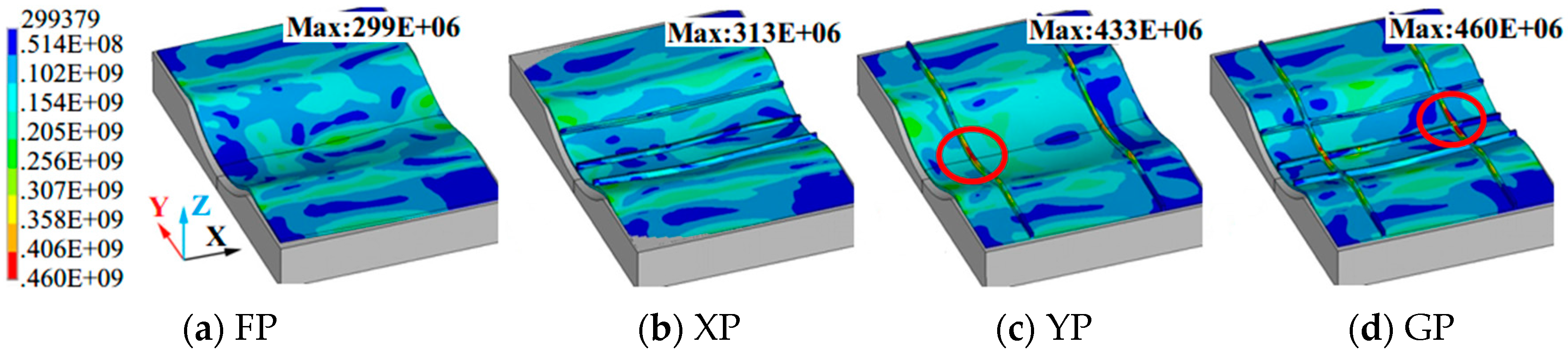
Figure 12.
Normal strain components of GP in position A: (a) at t = 51 μs; (b) at t = 139 μs; (c) at t = 394 μs; and (d) at t = 612 μs.
Figure 12.
Normal strain components of GP in position A: (a) at t = 51 μs; (b) at t = 139 μs; (c) at t = 394 μs; and (d) at t = 612 μs.
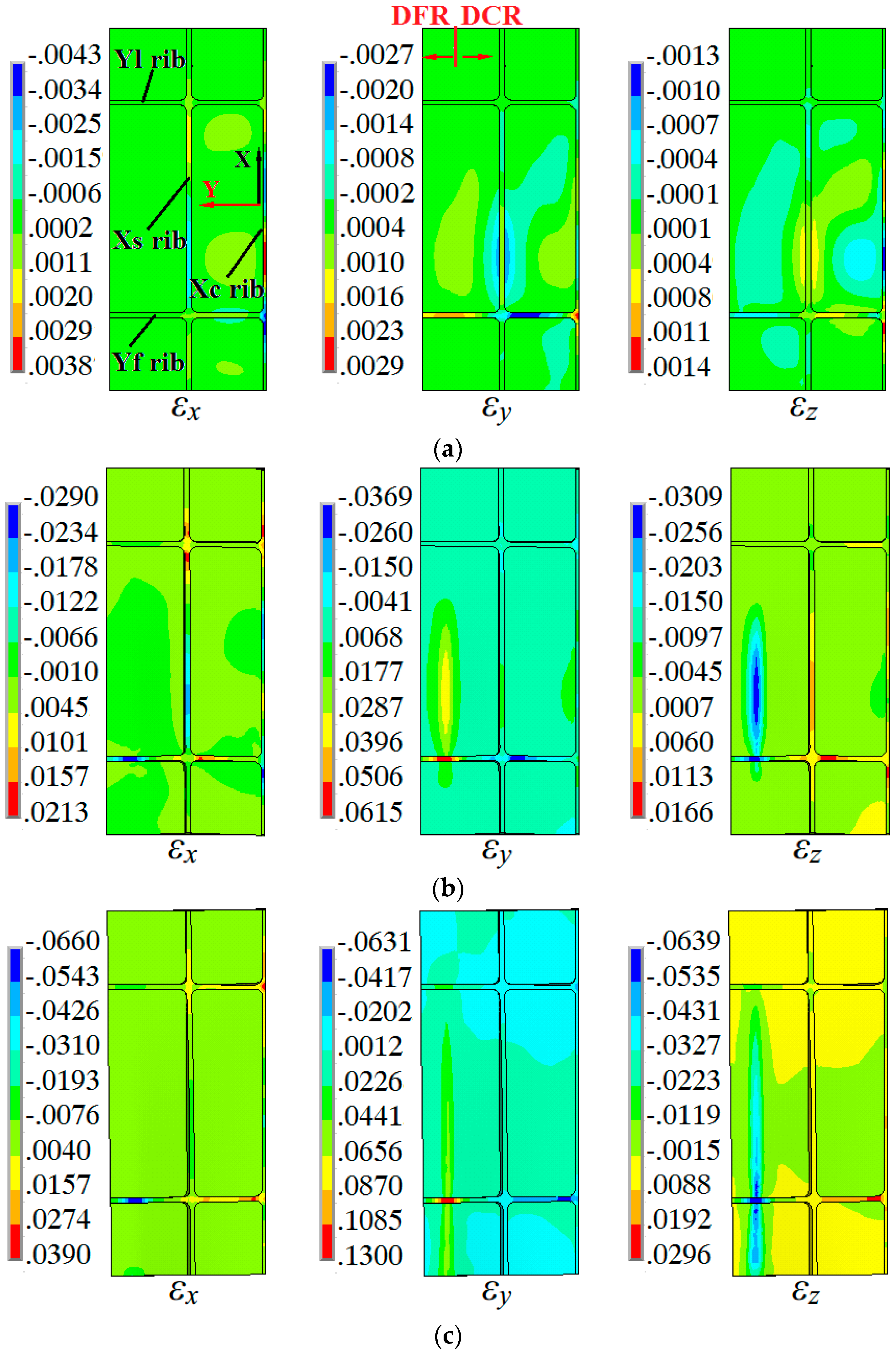

Figure 13.
Equivalent plastic strain distribution of four panels in the early stage of each discharge: (a) FP; (b) XP; (c) YP; and (d) GP.
Figure 13.
Equivalent plastic strain distribution of four panels in the early stage of each discharge: (a) FP; (b) XP; (c) YP; and (d) GP.


Figure 14.
Normal stress components (Pa) for the webs among the four panels at t = 139 μs in position A: (a) σx; (b) σy; and (c) σz.
Figure 14.
Normal stress components (Pa) for the webs among the four panels at t = 139 μs in position A: (a) σx; (b) σy; and (c) σz.


Table 1.
Sizes of the panels samples.
| Blank Form | Rib Height (mm) | Rib Width (mm) | Web Thickness (mm) |
|---|---|---|---|
| Flat panel (FP) | 0 | 0 | 2 |
| X-rib panel (XP) | 4 | 2 | 2 |
| Y-rib panel (YP) | 4 | 2 | 2 |
| Grid-rib panel (GP) | 4 | 2 | 2 |
Table 2.
Basic conditions in the simulation for electromagnetic incremental forming (EMIF).
| Discharge Capacity (μF) | X Coordinate at the 1st Pass (mm) | Voltage at the 1st Pass (kV) | X Coordinate at the 2nd Pass (mm) | Voltage at the 2nd Pass (kV) | X Coordinate at the 3rd Pass (mm) | Voltage at the 3rd Pass (kV) |
|---|---|---|---|---|---|---|
| 80 | −20 | 9.9 | −20 | 12 | +20 | 12 |
© 2017 by the authors. Licensee MDPI, Basel, Switzerland. This article is an open access article distributed under the terms and conditions of the Creative Commons Attribution (CC BY) license (http://creativecommons.org/licenses/by/4.0/).
Share and Cite
MDPI and ACS Style
Tan, J.; Zhan, M.; Gao, P.; Li, H. Electromagnetic Forming Rules of a Stiffened Panel with Grid Ribs. Metals 2017, 7, 559. https://doi.org/10.3390/met7120559
AMA Style
Tan J, Zhan M, Gao P, Li H. Electromagnetic Forming Rules of a Stiffened Panel with Grid Ribs. Metals. 2017; 7(12):559. https://doi.org/10.3390/met7120559
Chicago/Turabian StyleTan, Jinqiang, Mei Zhan, Pengfei Gao, and Hongwei Li. 2017. "Electromagnetic Forming Rules of a Stiffened Panel with Grid Ribs" Metals 7, no. 12: 559. https://doi.org/10.3390/met7120559
Note that from the first issue of 2016, this journal uses article numbers instead of page numbers. See further details here.