2. Material and Methods
The welding was performed on AA6061-T6 plate of 9.6 mm thickness.
Table 1 shows the nominal composition of the base metal used in this study; mechanical properties of base metal can be seen in
Table 2.
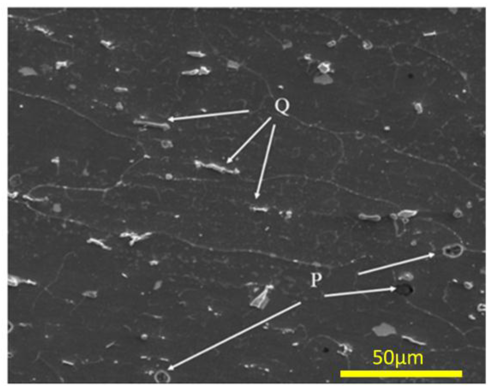
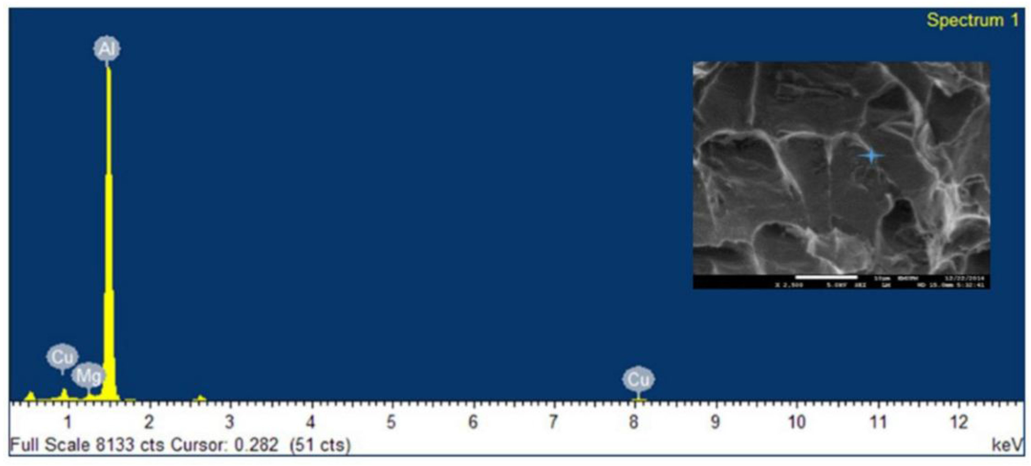
Figure 1 presents the AA6061-T6 alloy microstructure. Within the grains, white and grey spots are evident. These spots represent the constituent intermetallic particles. Some of them were seen being attacked by the etching processes (P in
Figure 1). As can be seen, grains were slightly elongated in a direction parallel to the rolling direction. The alloy fabrication process has shown its impact on the distribution of intermetallic particles as well. The intermetallic particles were seen aligned along the rolling direction (Q in
Figure 1). It is clear that at the longitudinal plane, the grains were seen elongated in a direction parallel to the rolling direction and the intermetallic particles were aligned along the rolling direction.
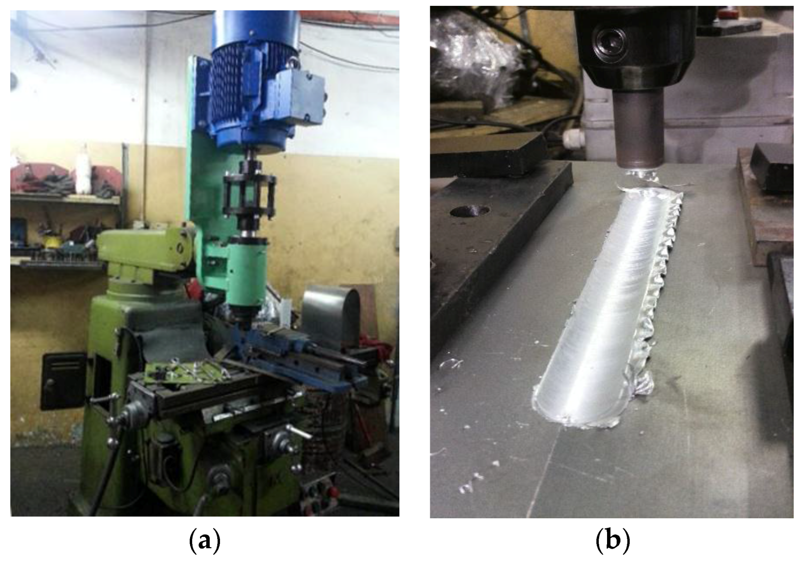
The joining process was carried out in a conventional machine, as a FSW machine shown in
Figure 2a. The head of machine (pin holder) was redesigned with a new cooling system to support high pressure and force which are needed during FSW of this high thickness joint. The plates were fabricated in butt joint design with (300 × 150 × 9.6) mm
3 dimensions. The fixation system and the welding process are presented in
Figure 2b.
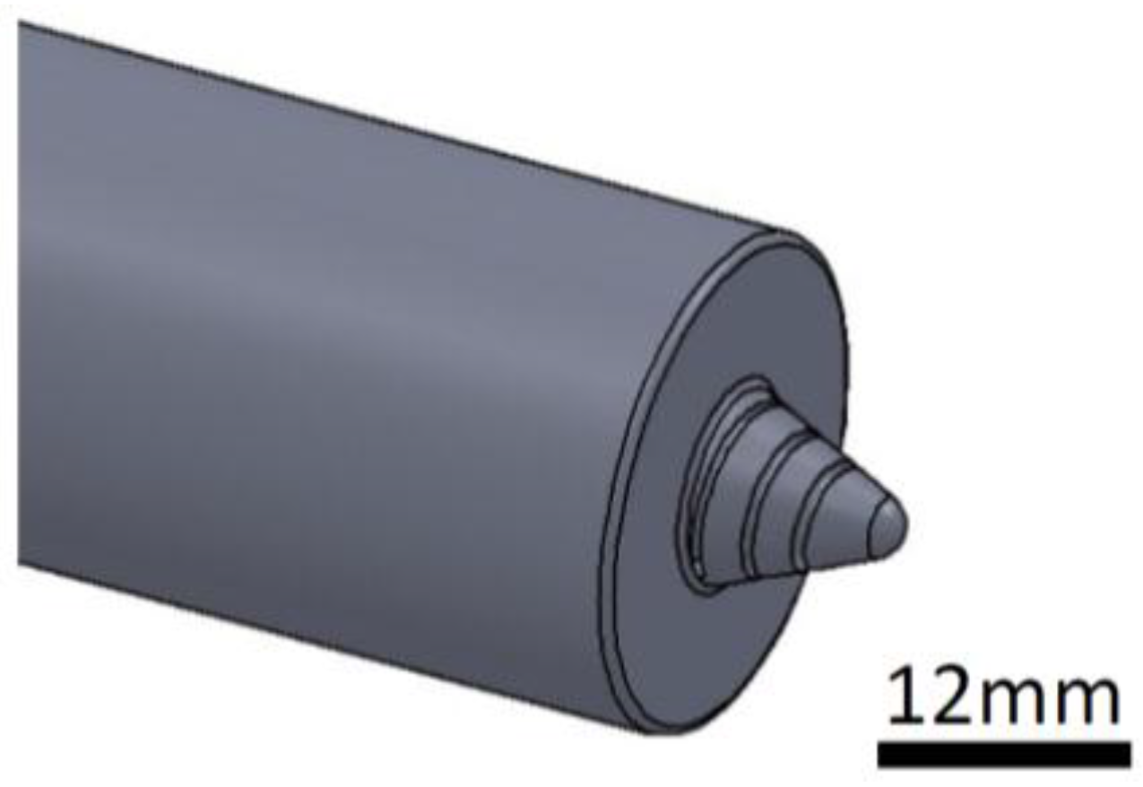
As can be seen in
Figure 3, the pin tip of the welding process has a conic shape with clockwise threads in order to improve the material flow. To obtain a better quality, the extreme pin tip is rounded [
16]. The key dimensions of the welding tool are summarized in
Table 3.
It should be noted that during the welding process, the tool rotation was kept unchanged (1480 rpm, counter clockwise). Further, the tool shoulder with three degree tilt angle was plunged into the joint of plate by a depth of around 0.1 mm. Dwell time at the start point of welding was 10 s. Three different welding speed were applied in this study; 63, 89 and 110 mm/min.
After doing FSW, the samples were cut perpendicularly to the weld line, to study the macro- and microstructure evolution along the welded joints. After grinding and final polishing up to one micron using diamond paste, samples were etched in Keller’s reagent for two minutes. Optical microscope (Leica DM1750 M, Buffalo Grove, IL, USA) and Scanning Electron Microscopy (FEI, Nova NanoSEM 230, Hillsboro, OR, USA) with Energy Dispersive X-Ray spectroscopy (FEI, Nova NanoSEM 230, Hillsboro, OR, USA) mapping were used for observing and analyzing the microstructures. For Electron Backscatter Diffraction (EBSD, Variable Pressure Scanning Electron Microscope–Hitachi S3200N, Raleigh, NC, USA) analysis, the samples were cut perpendicularly to the weld bead. After the polishing described above, a final polishing is performed by using 0.5 micron colloidal silica on the VibroMet® 2 Vibratory Polisher (Buehler, Lake Bluff, IL, USA) for six hours. The EBSD was done by Variable Pressure SEM and the resulting data were acquired using the EDAX TEAM software (TEAM™ EBSD, Mahwah, NJ, USA).
For mechanical investigation, tensile tests were performed at room temperature using a 100 KN Instron universal testing machine with the frame rail speed fixed at 2.0 mm/min. The number of tests and the dimensions of the samples for tensile test were selected in accordance with ISO 4136 standard [
17]. The fractured surfaces were investigated using SEM. Classical microhardness measurements were performed in a cross-section perpendicular to the weld line every 1 mm by applying an indentation load of 500 gf and a dwell-time of 10 s.
Acknowledgments
The authors are most grateful to the University Putra Malaysia for the financial support extended to this research work. We greatly appreciate the valuable advices of Saman Azhari in recent revising of this paper.
Author Contributions
Firouz Fadaeifard designed the experimental procedure. Khamirul Amin Matori supervised the entire research work. Firouz Fadaeifard, Liyana Zolkarnaia and Aliff Zairie Bin Abdul Rahim performed the experiment. Khamirul Amin Matori and Sidek Abd Aziz provided valuable scientific advices for the entire experiment. Firouz Fdaeifard analyzed data and wrote the paper while the final manuscript was revised by Khamirul Amin Matori and Sidek Abd Aziz.
Conflicts of Interest
The authors declare no conflict of interest.
References
- Hufnagel, W. Key to Aluminum Alloys; Aluminium-Verlag: Dusseldorf, Germany, 1999. [Google Scholar]
- Ramachandran, T.R. Advances in Aluminum Processing and its Automotive Application; the Indian Institute of Metals, Pune Chapter: Pune, India, 2006; pp. 28–32. [Google Scholar]
- Gharavi, F.; Matori, K.A.; Yunus, R.; Othman, N.I.; Fadaeifard, F. Corrosion evaluation of friction stir welded lap joints of AA6061-T6 aluminum alloy. Trans. Nonferr. Met. Soc. China 2016, 26, 684–696. [Google Scholar] [CrossRef]
- Török, I.; Juhász, K.; Meilinger, Á.; Balogh, A. Main characteristics of fusion and pressure welding of aluminium alloys. Prod. Process. Syst. 2012, 5, 91–106. [Google Scholar]
- Thomas, W.M.; Nicholas, E.D.; Needham, J.C.; Murch, M.G.; Temple Smith, P.; Dawes, C.J. Improvements Relating to Friction Welding. International Patent Application No. PCT/GB92/02203 Publication No. WO19930109935 A1, 6 December 1991. [Google Scholar]
- Liu, G.; Murr, L.E.; Niou, C.S.; McClure, J.C. Microstructural Aspects of the Friction Stir Welding of 6061-T6 Aluminum. Scr. Mater. 1997, 37, 355–361. [Google Scholar] [CrossRef]
- ASM International. ASM Handbook: Welding, Brazing and Soldering; ASM International: Materials Park, OH, USA, 1993; pp. 297–324. [Google Scholar]
- Knipström, K.E.; Pekkari, B. Friction stir welding process goes commercial. Weld. J. 1997, 76, 55–57. [Google Scholar]
- Mishra, R.S.; Ma, Z.Y. Friction stir welding and processing. Mater. Sci. Eng. Rep. 2005, 50, 1–78. [Google Scholar] [CrossRef]
- Leonard, A.J.; Lockyer, S.A. Flaws in friction stir welds. In Proceedings of 4th International Symposium on Friction Stir Welding, Park City, UT, USA, 14 May 2003.
- Lacki, P.; Kucharczyk, Z.; Śliwa, R.E.; Gałaczyński, T. Effect of tool shape on temperature field in friction stir spot welding. Arch. Metal. Mater. 2013, 58, 595–599. [Google Scholar] [CrossRef]
- Thomas, W.M.; Staines, D.G.; Norris, I.M.; de Frias, R. Friction stir welding tools and developments. Weld. World 2003, 47, 10–17. [Google Scholar] [CrossRef]
- Carlone, P.; Palazzo, G.S. Influence of process parameters on microstructure and mechanical properties in AA2024-T3 friction stir welding. Metallogr. Microstruct. Anal. 2013, 1, 213–222. [Google Scholar] [CrossRef]
- Velotti, C.; Astarita, A.; Buonadonna, P.; Dionoro, G.; Langella, A.; Paradiso, V.; Prisco, U.; Scherillo, F.; Squillace, A.; Tronci, A. FSW of AA 2139 plates: Influence of the temper state on the mechanical properties. Key Eng. Mater. 2013, 554–557, 1065–1074. [Google Scholar] [CrossRef]
- Integrated, M. Mechanical and Metallurgical Characterization of Friction Stir Welding AA6351. Ph.D. Thesis, Mewar University, Rajasthan, India, 2015. [Google Scholar]
- Dawes, C.J.; Threadgill, P.L.; Spurgin, E.J.R.; Staines, D.G. Development of the new friction stir technique for welding aluminium. TWI GSP 1995, 5651, 1994–1997. [Google Scholar]
- ISO 4136:2012. Destructive Tests on Welds in Metallic Materials—Transverse Tensile Test. Available online: http://www.iso.org/iso/catalogue_detail.htm?csnumber=62317 (accessed on 30 November 2012).
- Sedmak, A.; Kumar, R.; Chattopadhyaya, S.; Hloch, S.; Tadić, S.; Djurdjević, A.; Čeković, I.; Dončeva, E. Heat input effect of friction stir welding on aluminum alloy AA 6061-T6 welded joint. Therm. Sci. 2016, 20, 637–641. [Google Scholar] [CrossRef]
- Kumbhar, N.T.; Bhanumurthy, K. Friction stir welding of Al 6061 alloy. Asian J. Exp. Sci. 2008, 22, 63–74. [Google Scholar]
- Arbegast, W.J. Modeling friction stir joining as a metalworking process. In Proceedings of the Hot Deformation of Aluminum Alloys III, Warrendale, PA, USA, 2003; pp. 313–327.
- Arbegast, W.J. Using process forces as a statistical process control tool for friction stir welds. In Proceedings of the 2005 TMS Annual Meeting: Friction Stir Welding and Processing III, San Francisco, California, USA, February 2005; pp. 193–204.
- Colligan, K. Material flow behavior during friction welding of aluminum. Weld J. 1999, 75, 229–237. [Google Scholar]
- Zhang, Y.N.; Cao, X.; Larose, S.; Wanjara, P. Review of tools for friction stir welding and processing. Can. Metall. Quart. 2012, 51, 250–261. [Google Scholar] [CrossRef]
- Kumar, K.; Kailas, S.V. The role of friction stir welding tool on material flow and weld formation. Mater. Sci. Eng. A 2008, 485, 367–374. [Google Scholar] [CrossRef]
- Frigaard, Ø.; Grong, Ø.; Midling, O.T. A process model for friction stir welding of age hardening aluminum alloys. Metall. Mater. Trans. A 2001, 32, 1189–1200. [Google Scholar] [CrossRef]
- Fadaeifard, F.; Matori, K.A.; Toozandehjani, M.; Daud, A.R.; Ariffin, M.K.A.M.; Othman, N.K.; Gharavi, F.; Ramzani, A.H.; Ostovan, F. Influence of rotational speed on mechanical properties of friction stir lap welded 6061-T6 Al alloy. Trans. Nonferr. Met. Soc. China 2014, 24, 1004–1011. [Google Scholar] [CrossRef]
- Elangovan, K.; Balasubramanian, V.; Babu, S. Predicting tensile strength of friction stir welded AA6061 aluminum alloy joints by a mathematical model. Mater. Des. 2009, 30, 188–193. [Google Scholar] [CrossRef]
- Nandan, R.; DebRoy, T.; Bhadeshia, H.K.D.H. Recent advances in friction-stir welding–process, weldment structure and properties. Prog. Mater. Sci. 2008, 53, 980–1023. [Google Scholar] [CrossRef]
- ASTM E112-96(2004), Standard Test Methods for Determining Average Grain Size, ASTM International, West Conshohocken, PA, USA, 2004. Available online: https://www.astm.org/DATABASE.CART/HISTORICAL/E112-96R04.htm (accessed on 11 January 2004).
- Doherty, R.; Hughes, D.; Humphreys, F.; Jonas, J.; Jensen, D.J.; Kassner, M. Current issues in recrystallization: A review. Mater. Sci. Eng. A 1997, 238, 219–274. [Google Scholar] [CrossRef]
- Brandon, D. The structure of high-angle grain boundaries. Acta Metall. 1966, 14, 1479–1484. [Google Scholar] [CrossRef]
- Chen, Z.W.; Pasang, T.; Qi, Y. Shear flow and formation of Nugget zone during friction stir welding of aluminium alloy 5083-O. Mater. Sci. Eng. A 2008, 474, 312–326. [Google Scholar] [CrossRef]
- Kadlec, M.; Růžek, R.; Nováková, L. Mechanical behavior of AA 7475 friction stir welds with the kissing bond defect. Int. J. Fatigue 2015, 74, 7–19. [Google Scholar] [CrossRef]
- Niranjani, V.L.; Kumar, K.H.; Sarma, V.S. Development of high strength Al-Mg-Si AA6061 alloy through cold rolling and ageing. Mater. Sci. Eng. A 2009, 515, 169–174. [Google Scholar] [CrossRef]
Figure 1.
Scanning Electron Microscopy (SEM) image of base metal AA6061-T6.
Figure 2.
(a) A vertical milling machine used for FSW experiments. (b) The real shape of fixture (clamping) used to restrain the plates during FSW.
Figure 3.
Shape of the welding tool designed in this work.
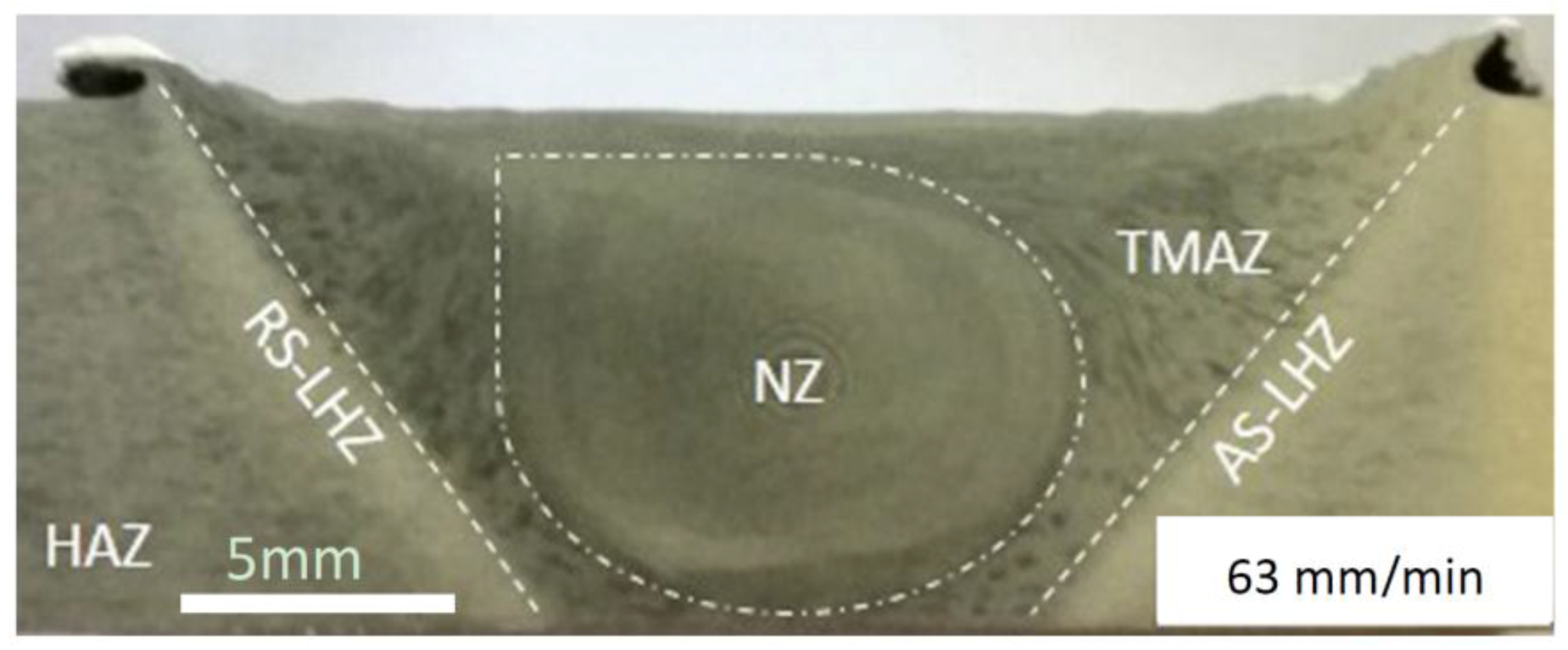
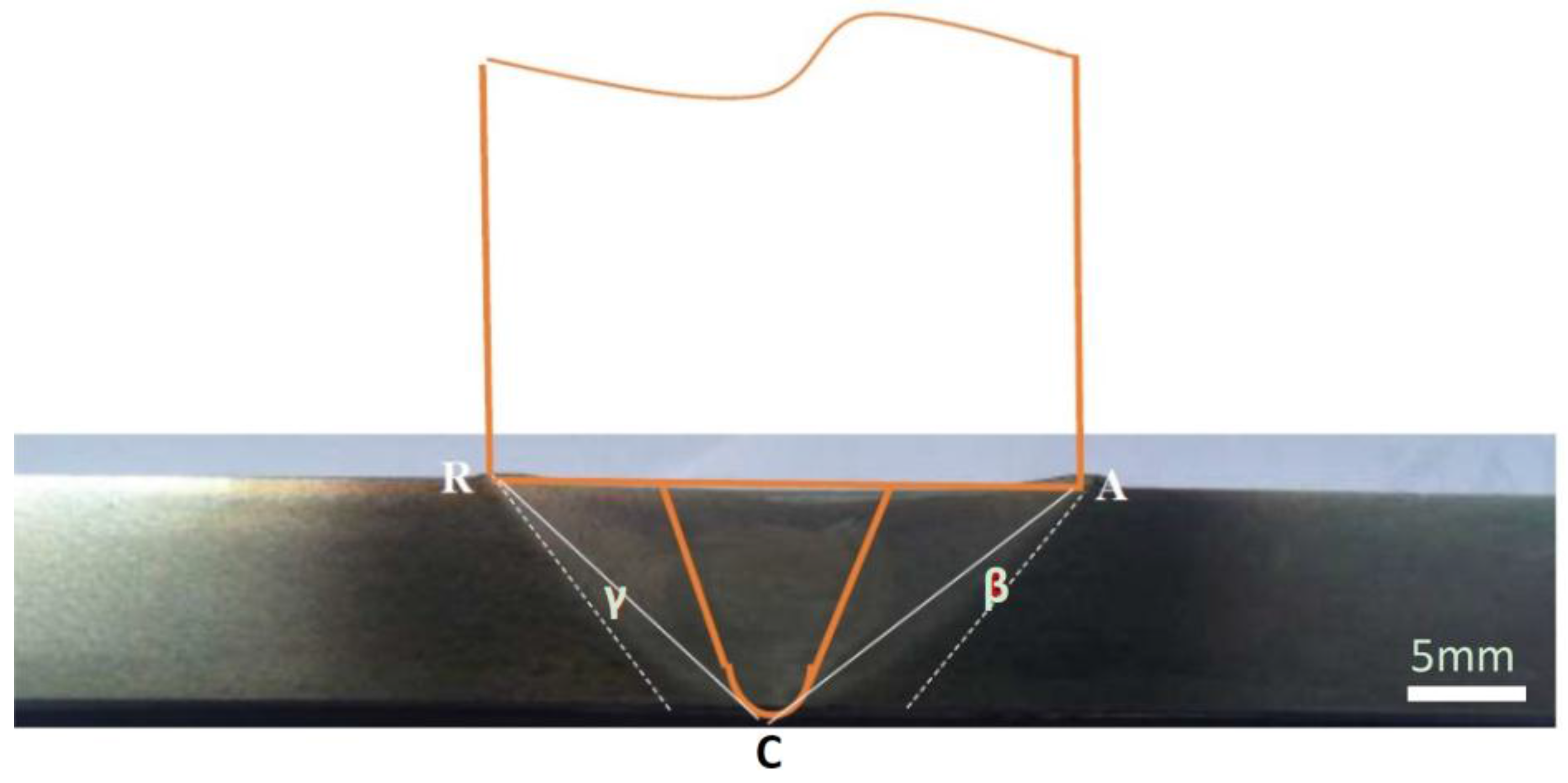
Figure 4.
Macrograph of friction stir welded joint in 63 mm/min.
Figure 5.
Schematic of FSW and affected area by shoulder and pin used in this study.
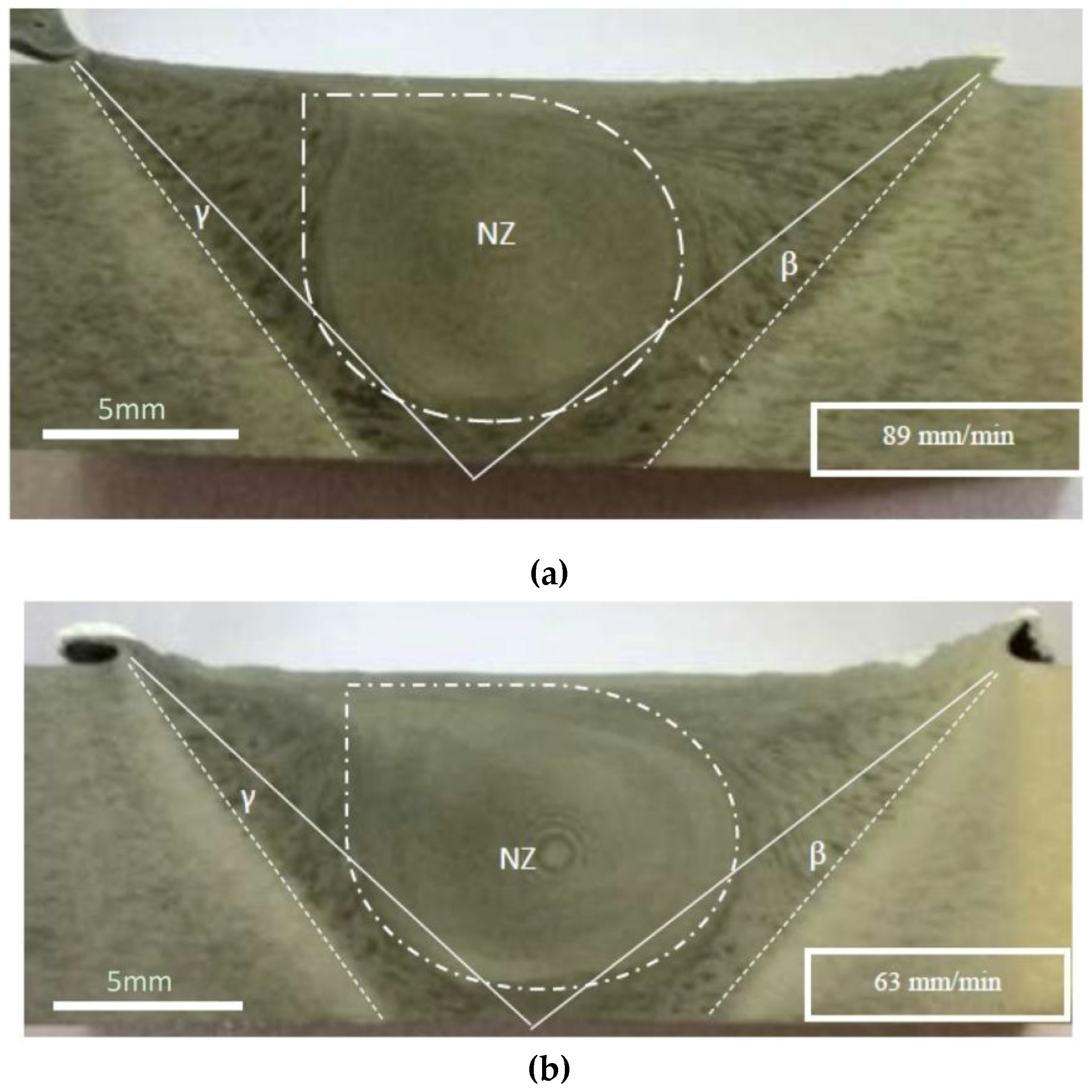
Figure 6.
Cross-section macrostructure of butt joint section AA6061-T6 Al alloy at different welding speeds. (a) 89 mm/min welding speed (b) 63 mm/min welding speed.
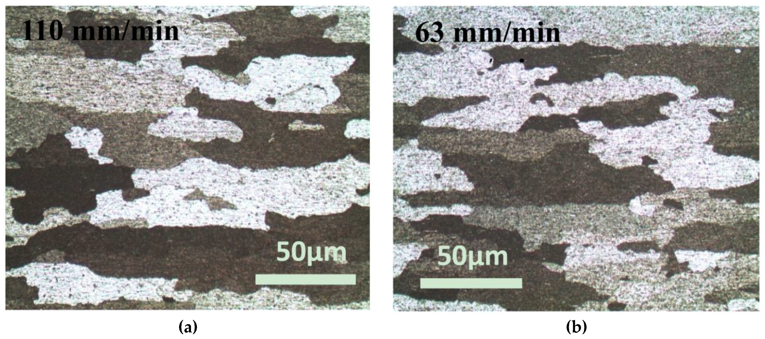
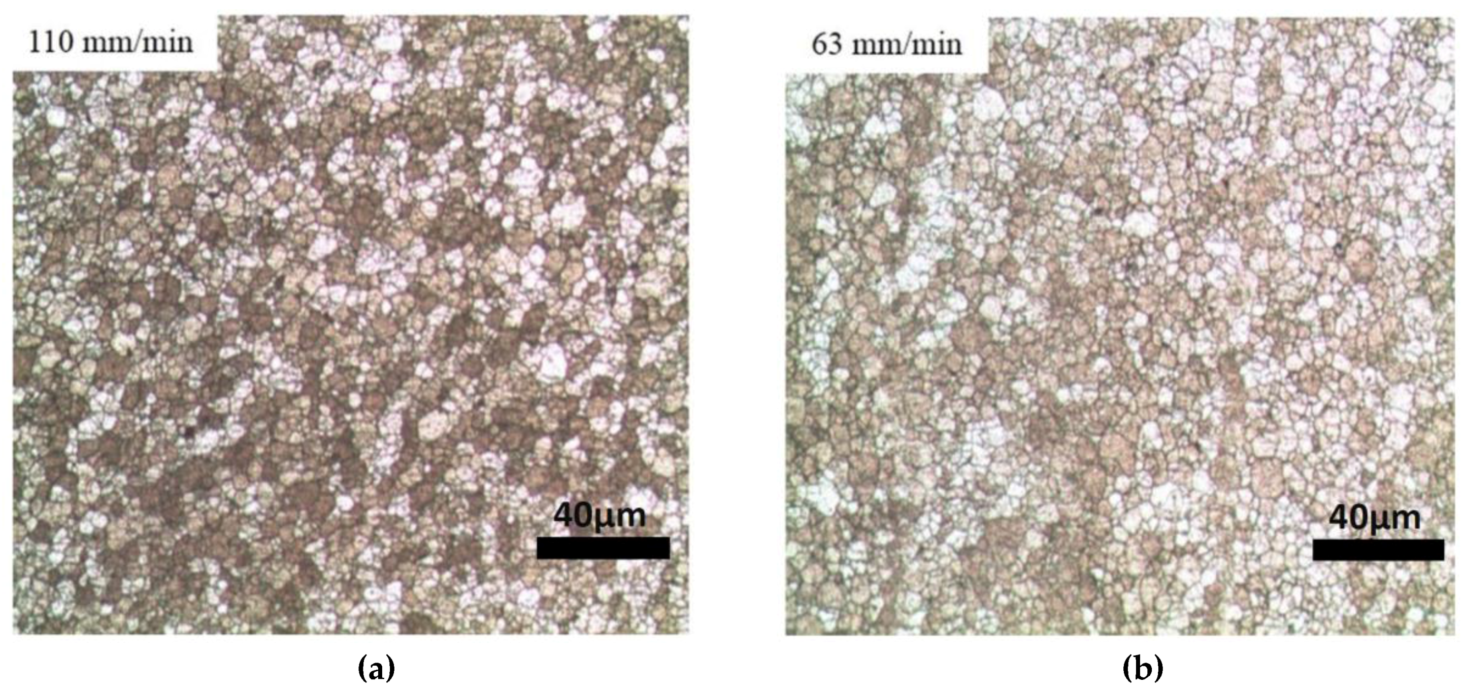
Figure 7.
Optical images of Heat Affected Zones (HAZs) of different welding speed (a) 110 mm/min welding speed (b) 63 mm/min welding speed.
Figure 8.
Optical microstructure of Nugget Zone (NZ) in highest (a) and lowest (b) welding speed (a) 110 mm/min welding speed (b) 63 mm/min welding speed.
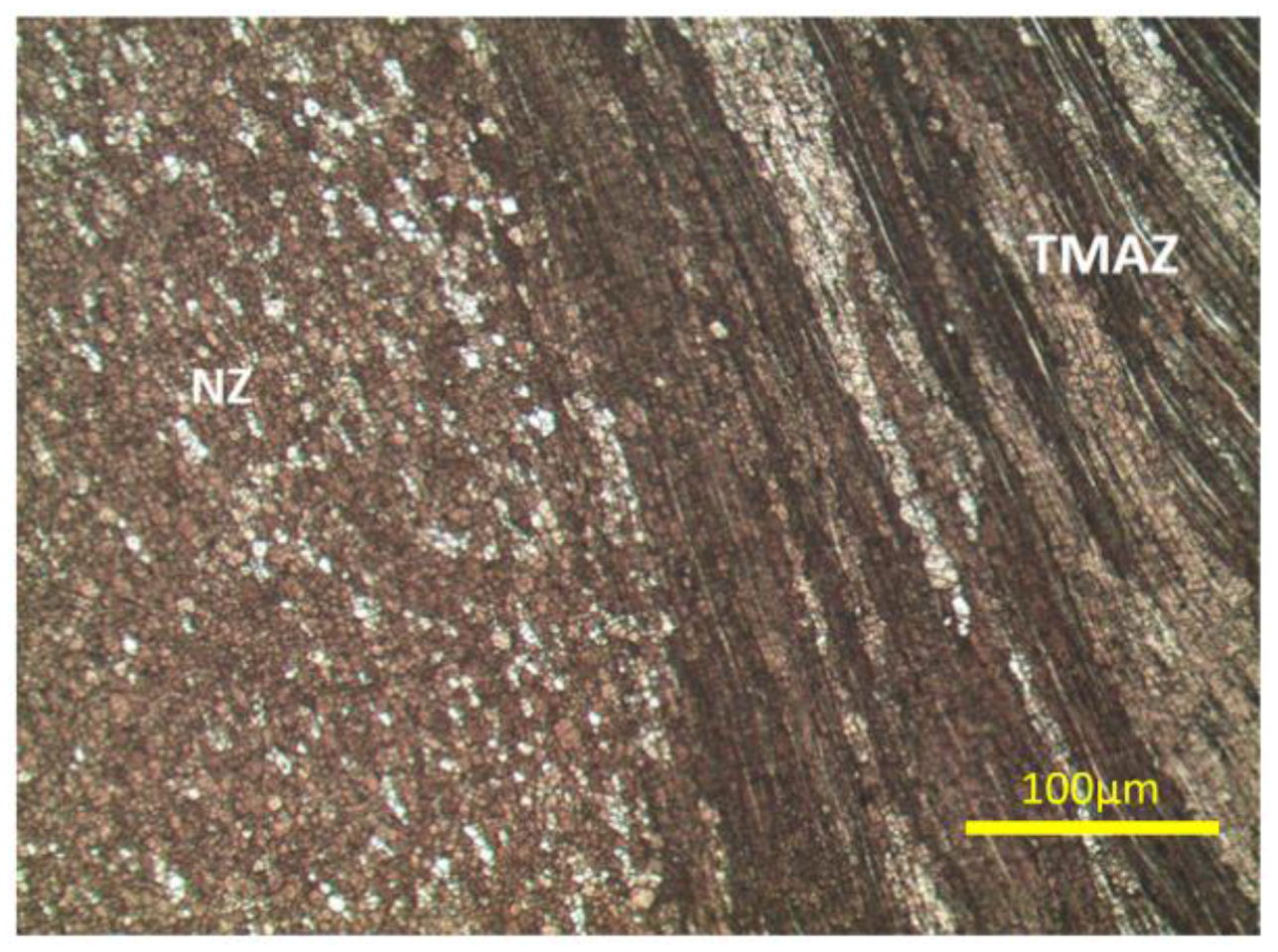
Figure 9.
Optical image of NZ and TMAZ (110 mm/min) 100X.
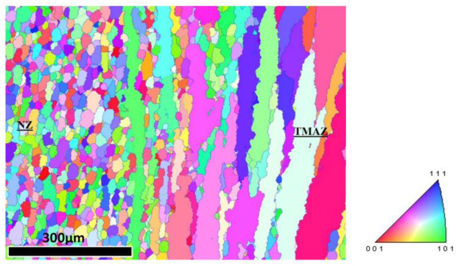
Figure 10.
Grain orientation analyzed by Electron backscatter diffraction (EBSD) of NZ and TMAZ (110 mm/min).
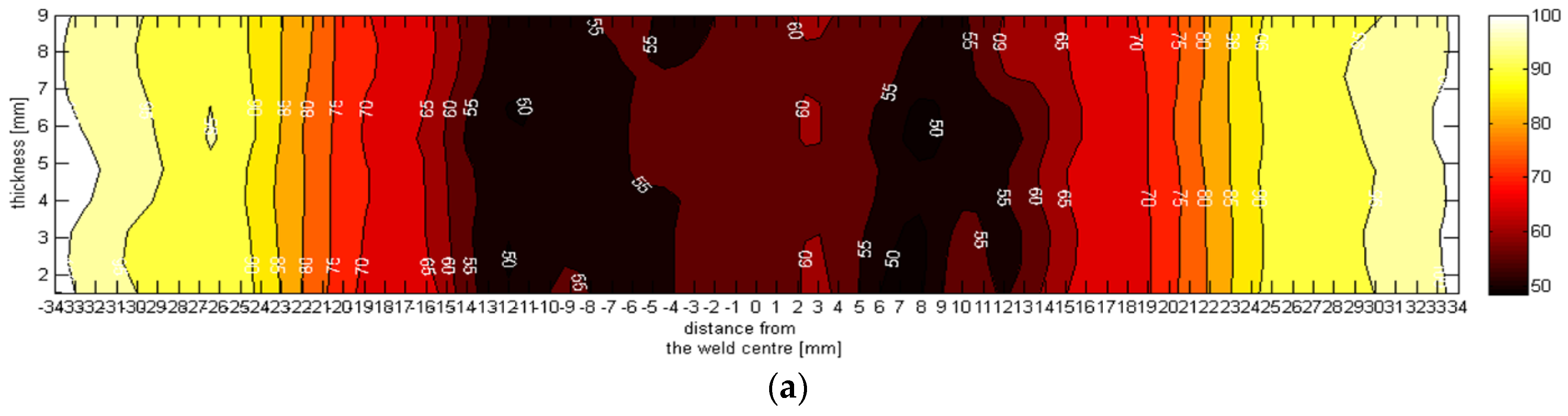
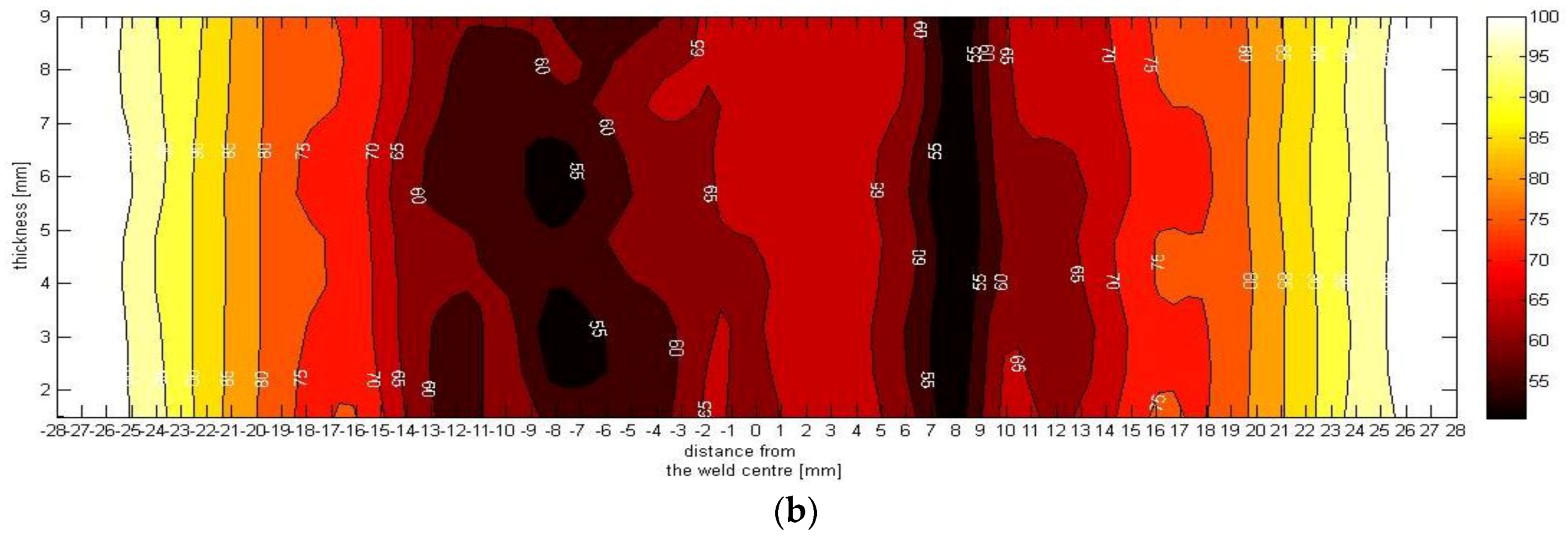
Figure 11.
Hardness mapping at: (a) 63 mm/min; and (b) 110 mm/min.
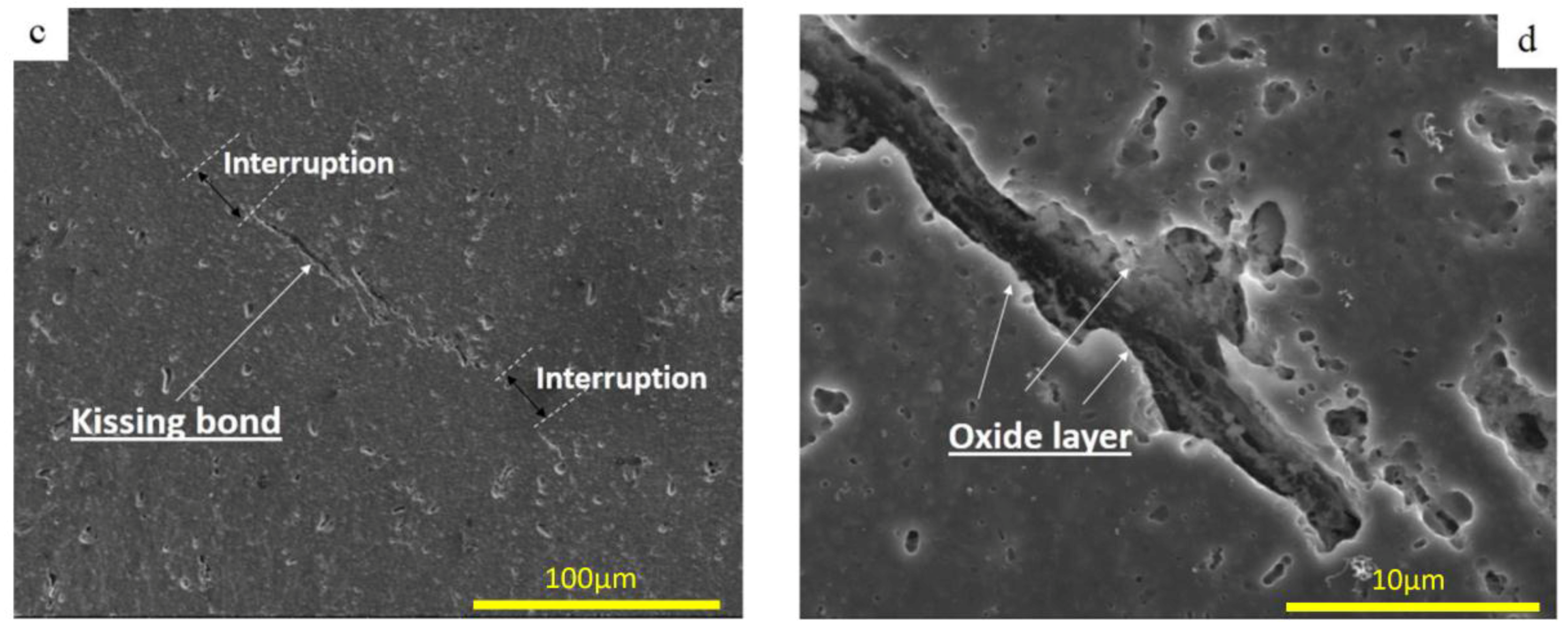
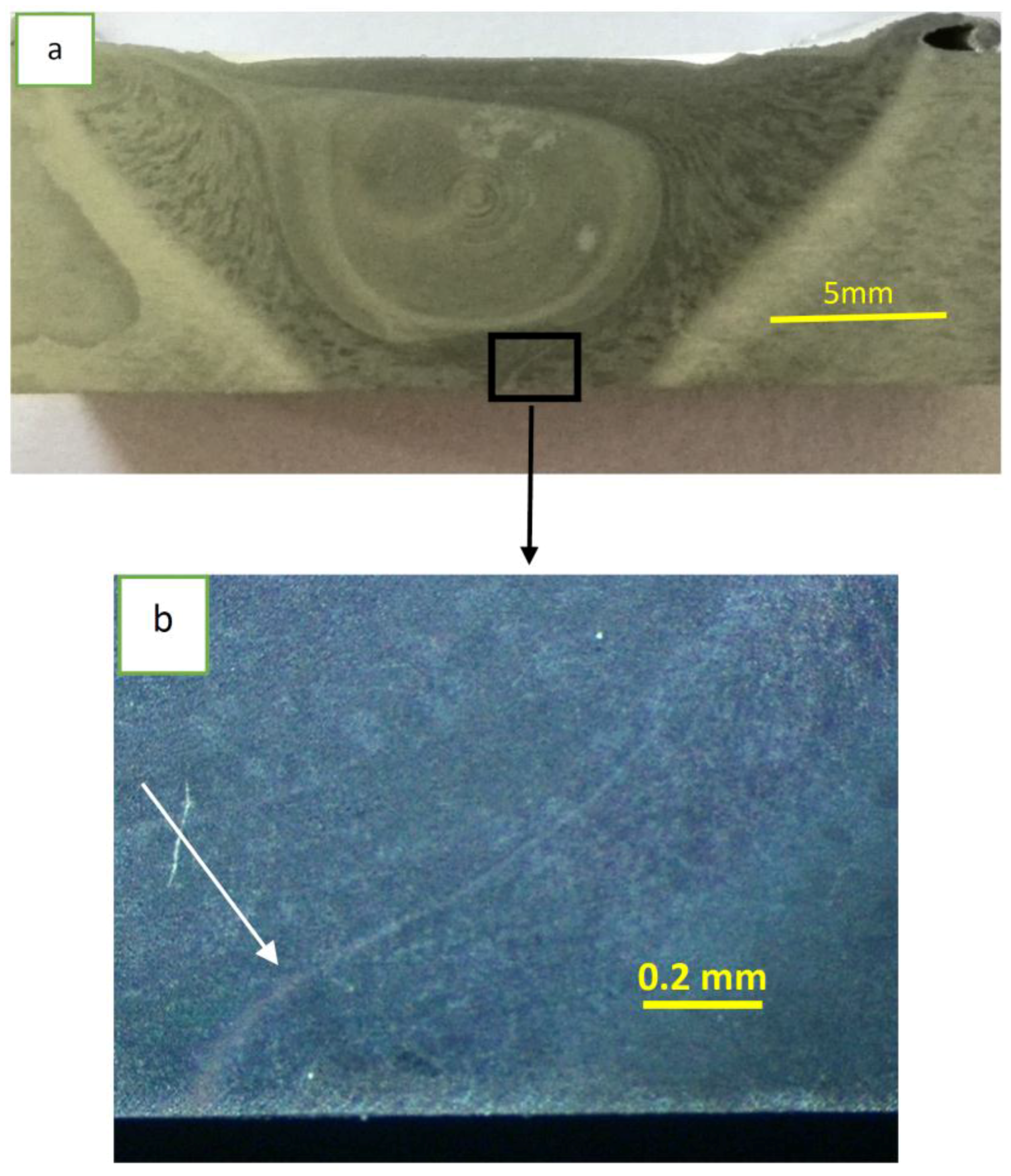
Figure 12.
Kissing bond in 89 mm/min: (a,b) macrograph of kissing bond in root; and (c,d) SEM image of kissing bond.
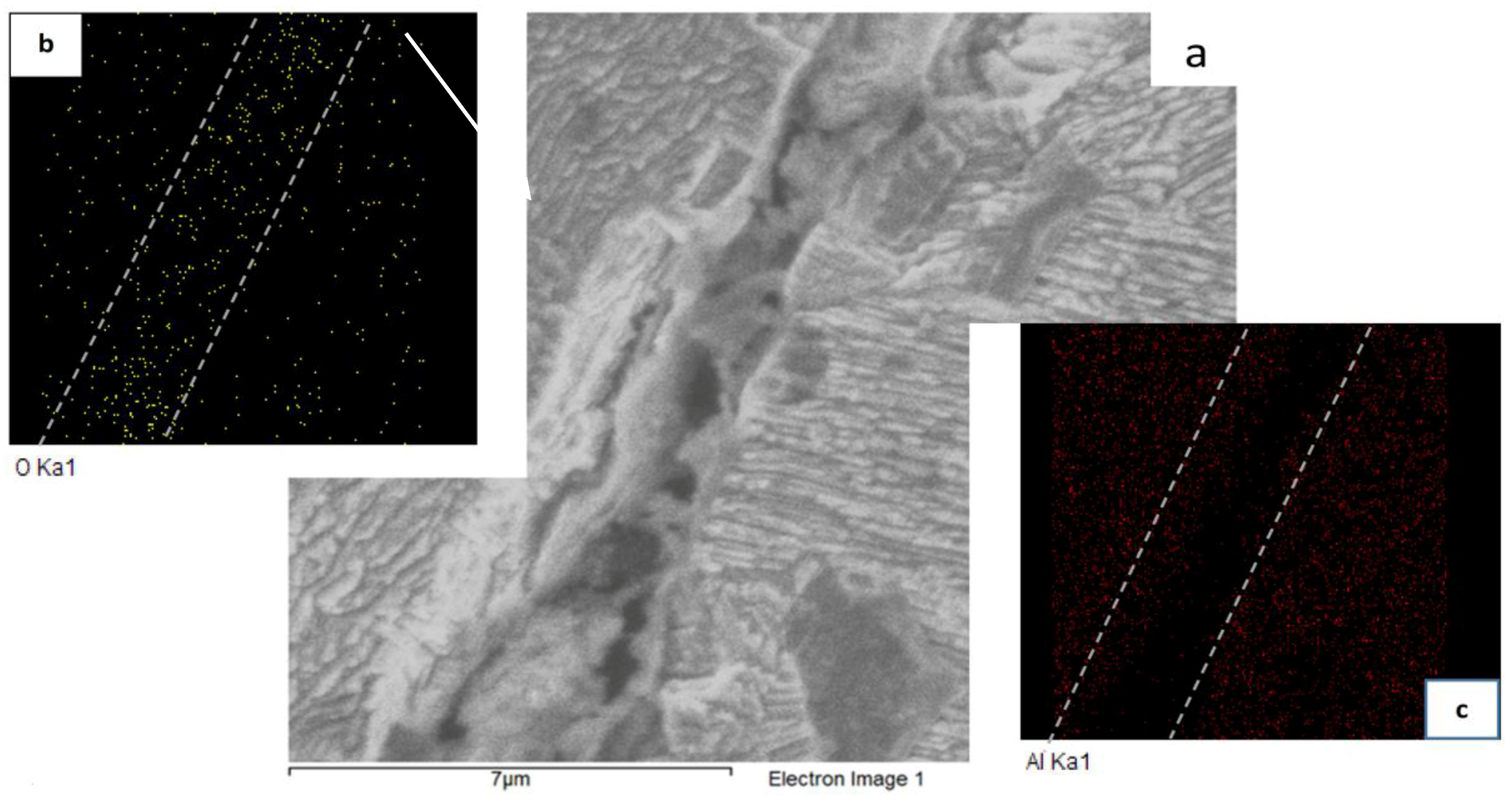
Figure 13.
EDX mapping of oxide layer around kissing bond: (a) SEM image of kissing bond; (b) distribution of oxygen around the kissing bond in yellow color; and (c) distribution of Al around kissing bond in red color.
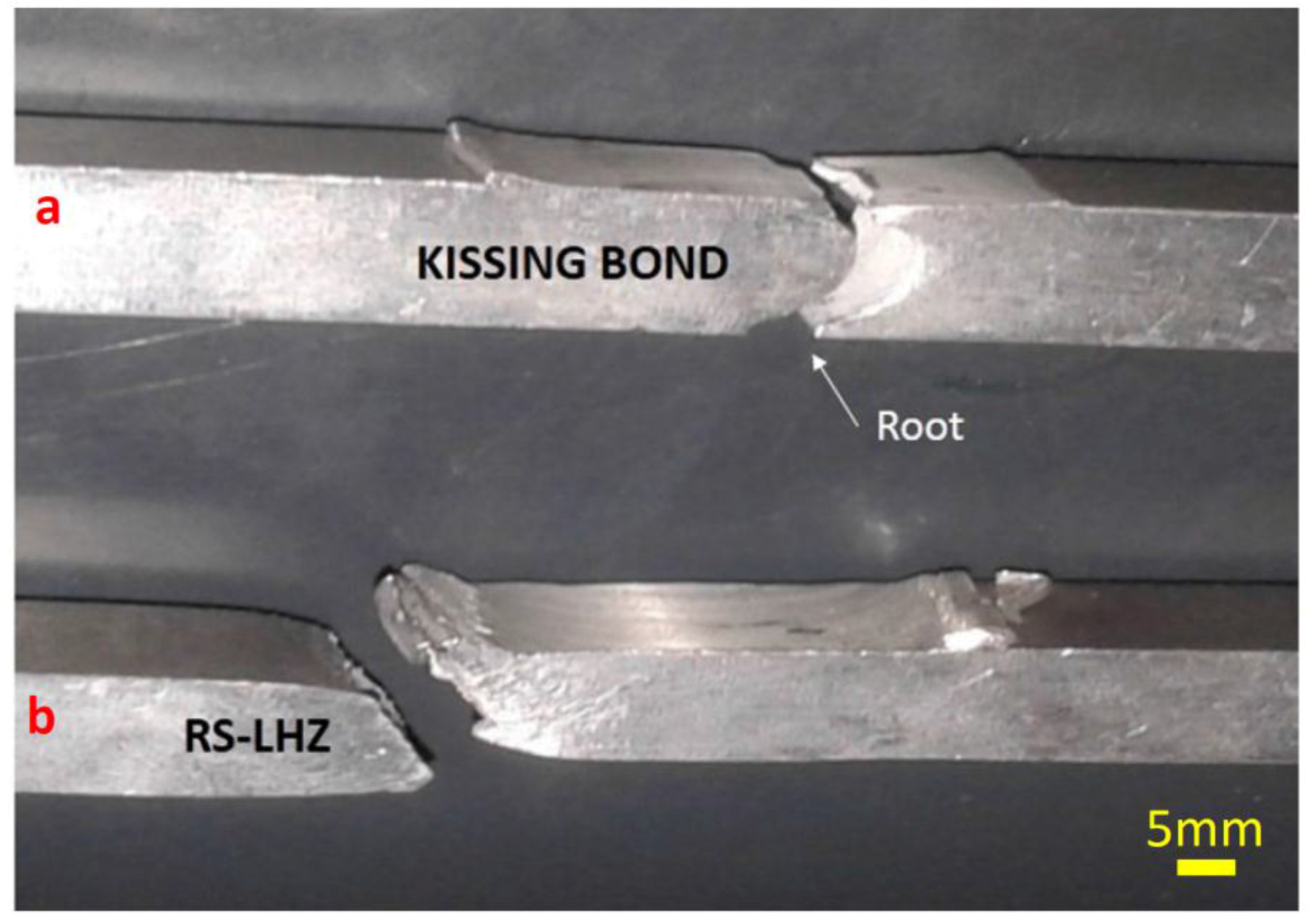
Figure 14.
Fracture location: (a) As-weld; and (b) Machined.
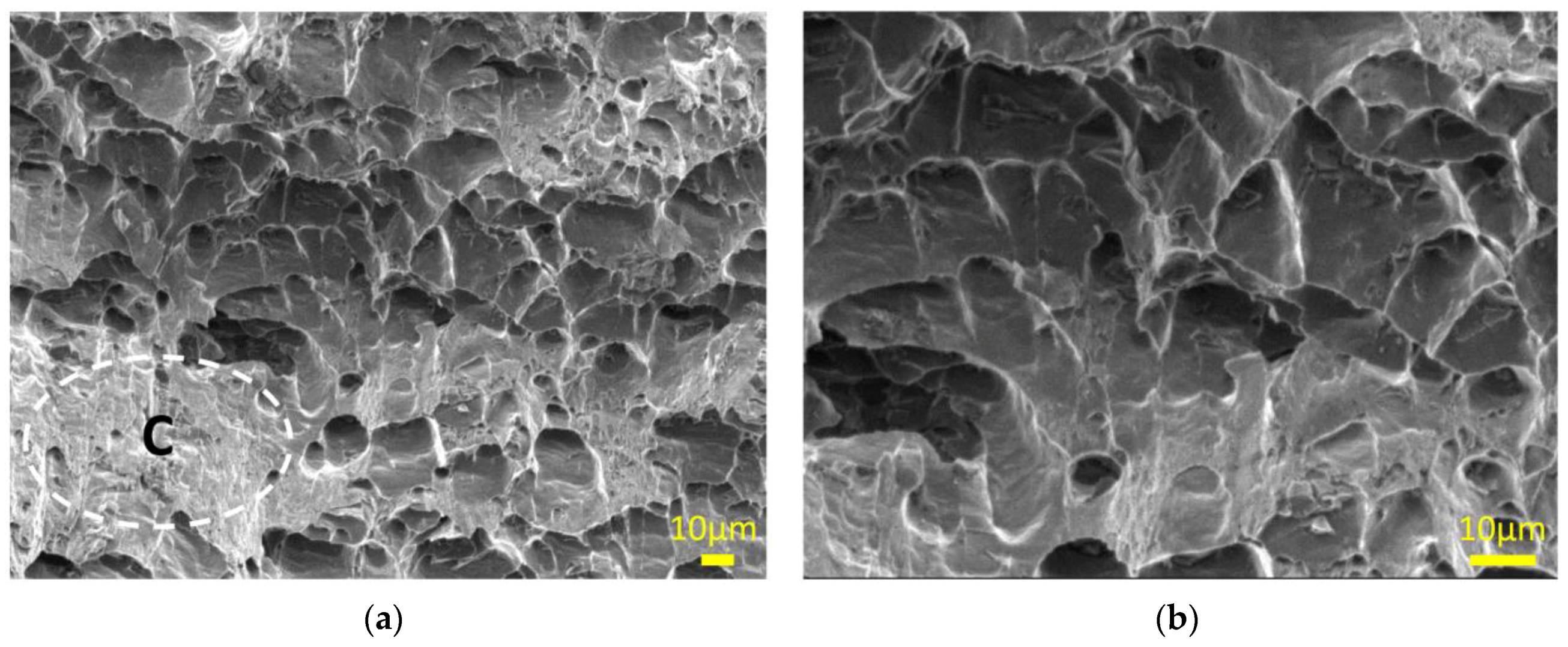
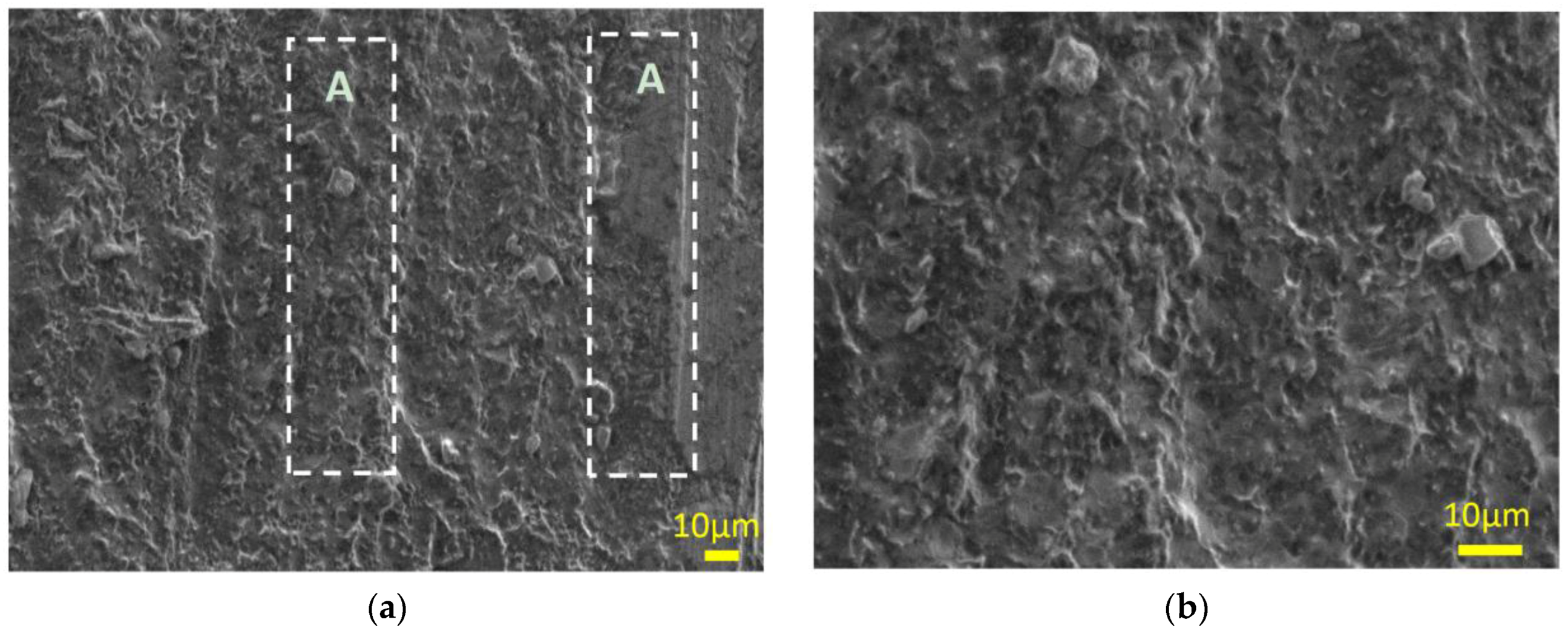
Figure 15.
SEM image from kissing bond location: (a) 500×; and (b) 1000×.
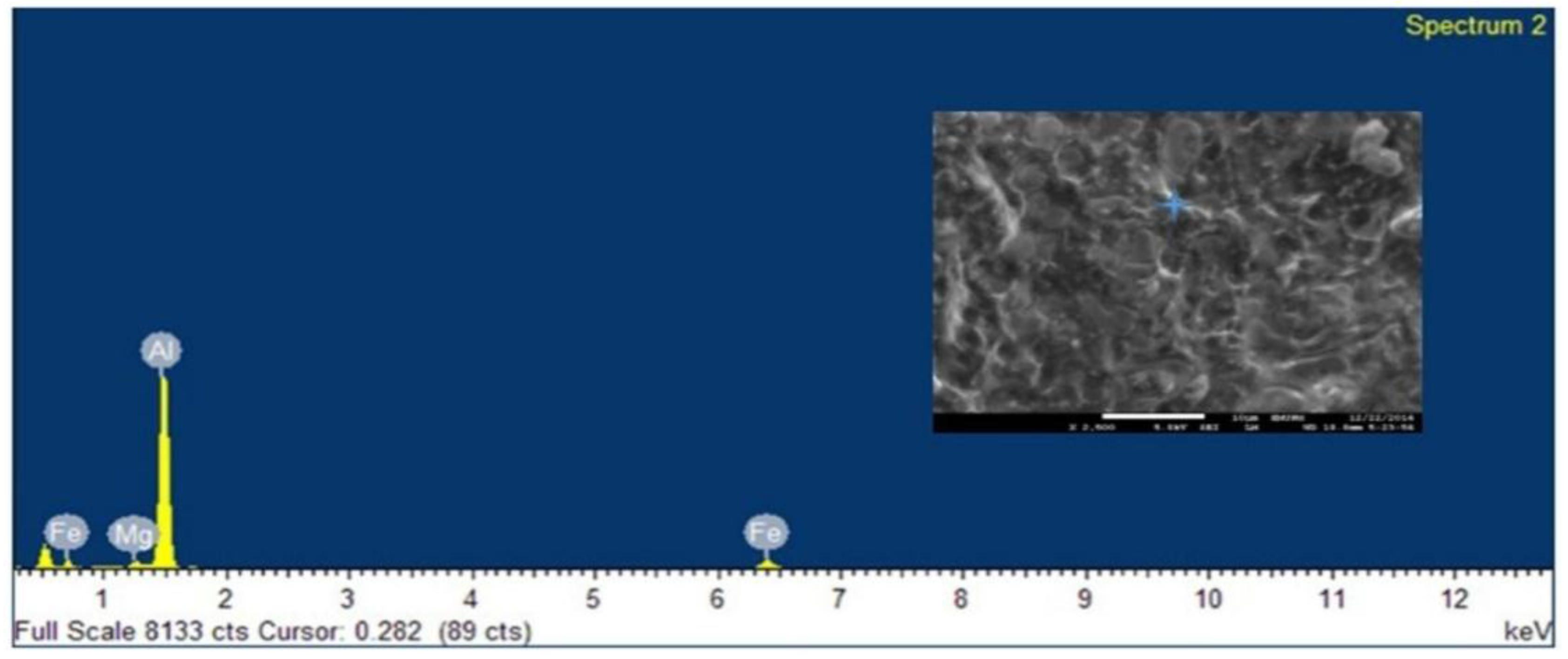
Figure 16.
EDX analysis of kissing bond fracture location.
Figure 17.
SEM image from RS-LHZ location: (a) 500×; and (b) 1000×.
Figure 18.
EDX analysis of RS-LHZ fracture location.
Table 1.
Nominal chemical composition of materials used in FSW experiments (wt. %).
| Material | Si | Mg | Cu | Fe | Mn | Cr | Zn | Ti | Al |
|---|
| AA6061-T6 | 0.54 | 0.96 | 0.27 | 0.43 | 0.05 | 0.04 | 0.02 | 0.02 | Balance |
Table 2.
Mechanical properties of the 6061-T6 aluminum alloy.
| Yield Strength (MPa) | Ultimate Strength (MPa) | Elongation (%) | Hardness (HV) |
|---|
| 269 ± 2 | 300 ± 1 | 15 ± 0 | 105 ± 3.1 |
Table 3.
Summary of dimensions of the tools used in Friction Stir Welding (FSW) experiments.
| Purpose | Lpin (mm) | Dpin (mm) | Dshoulder (mm) | Pitch (mm) | Cone Angle |
|---|
| FSW of AA 6061-T6 | 9.5 | 10.50 | 24 | 1.2 | 60° |
Table 4.
γ and β deviation for different welding speed.
| Deviation Angle | Welding Speed |
|---|
| 63 mm/min | 89 mm/min | 110 mm/min |
|---|
| γ deviation | 15° | 12° | 12° |
| β deviation | 16° | 16° | 15° |
Table 5.
Grain size of Nugget Zones (NZs) and Heat Affected Zones (HAZs).
| Sample | Welding Speed (mm/min) | Average Grain Size NZ (μm) | Average Grain Size HAZ (μm) | Average Grain Size Base Metal (µm) |
|---|
| 1 | 63 | 16.1 | 133 | 125 |
| 2 | 89 | 11 | 128 | 125 |
| 3 | 110 | 10.7 | 128 | 125 |
Table 6.
Mechanical properties obtained by tensile tests (average).
| No. | Welding Speed (mm/min) | Fracture (Location) | Ultimate Tensile Strength (UTS in MPa) RS-LHZ/Kissing Bond | Yield Strength (YS in MPa) RS-LHZ/Kissing Bond | Elongation (%) |
|---|
| 1 | 63 | RS-LHZ | 132 ± 2.1 | 127 ± 1.4 | 14 ± 0.4 |
| 2 | 89 | RS-LHZ/Kissing bond | (141 ± 1.73)/(117 ± 2.2) | (137 ± 1.4)/(97 ± 1.9) | (16 ± 0.3)/(3.6 ± 0.13) |
| 3 | 110 | RS-LHZ/Kissing bond | (159 ± 2)/(119 ± 1.6) | (134 ± 1.7)/(95 ± 2) | (16 ± 0.5)/(3.5 ± 0.15) |
© 2017 by the authors. Licensee MDPI, Basel, Switzerland. This article is an open access article distributed under the terms and conditions of the Creative Commons Attribution (CC BY) license ( http://creativecommons.org/licenses/by/4.0/).


