Article

Titanium Powder Sintering in a Graphite Furnace and Mechanical Properties of Sintered Parts

Department of Chemical and Materials Engineering, The University of Auckland, Private Bag 92019, Auckland 1142, New Zealand
*
Authors to whom correspondence should be addressed.
Metals 2017, 7(2), 67; https://doi.org/10.3390/met7020067
Submission received: 23 January 2017 / Revised: 19 February 2017 / Accepted: 20 February 2017 / Published: 22 February 2017
(This article belongs to the Special Issue Titanium Alloys 2017)

Abstract

:
Recent accreditation of titanium powder products for commercial aircraft applications marks a milestone in titanium powder metallurgy. Currently, powder metallurgical titanium production primarily relies on vacuum sintering. This work reported on the feasibility of powder sintering in a non-vacuum furnace and the tensile properties of the as-sintered Ti. Specifically, we investigated atmospheric sintering of commercially pure (C.P.) titanium in a graphite furnace backfilled with argon and studied the effects of common contaminants (C, O, N) on sintering densification of titanium. It is found that on the surface of the as-sintered titanium, a severely contaminated porous scale was formed and identified as titanium oxycarbonitride. Despite the porous surface, the sintered density in the sample interiors increased with increasing sintering temperature and holding time. Tensile specimens cut from different positions within a large sintered cylinder reveal different tensile properties, strongly dependent on the impurity level mainly carbon and oxygen. Depending on where the specimen is taken from the sintered compact, ultimate tensile strength varied from 300 to 580 MPa. An average tensile elongation of 5% to 7% was observed. Largely depending on the interstitial contents, the fracture modes from typical brittle intergranular fracture to typical ductile fracture.

1. Introduction

Structural applications of titanium and its alloys are limited because of the high cost of production despite the fact that titanium exhibits admirable combined properties such as high strength-to-weight ratio and excellent corrosion resistance [1,2]. In comparison with the mainstream titanium production processes such as casting and wrought, the major advantage of powder metallurgical (PM) methods including conventional press-and-sinter and novel additive manufacturing [3,4] is the potential of cost reduction resulting from its near-net-shaping ability [5]. In recent major milestone developments in the PM titanium industry, near-net-shaped Ti-6Al-4V products have been approved for commercial airplane components by Boeing (Seattle, WA, USA) [5]. The manufacture of titanium powder metal products has received standardized quality management system AS9100/ISO9001 certification in April 2013 [6]. Titanium powders are generally sintered under vacuum rather than in an atmosphere such as argon or helium so as to obtain high densification and superior mechanical properties [7]. Vacuum sintering with a pressure of the order of 10−2 Pa or lower [8,9,10,11] can effectively control the active reaction between titanium and interstitial impurities such as oxygen, nitrogen and carbon. The mechanical properties of as-sintered titanium are highly sensitive to the interstitials [5,12]. For example, in samples with a similar sintered density of 98%, the ductility of press-and-sintered commercial purity titanium with an oxygen content of 3000 ppm (elongation: 11%) is less than 1/3 of that for Ti containing 700 ppm oxygen (elongation: 37.1%) [7,13]. Vacuum sintering can also remove detrimental volatiles such as chlorides that pre-exist in titanium sponges and help with densification [13,14]. However, vacuum sintering is a batch process and has high capital equipment requirement. Possible continuous mass production is suggested to be realized by atmospheric sintering so as to reduce the production cost [14].
In 1937, Kroll conducted the first sintering trials of 14 Ti binary alloys in argon atmosphere [13]. Subsequent work in the late 1940s and early 1950s saw some other examples of the sintering of titanium mill products [7,15]. Limberg et al. [16] studied the influence of sintering atmosphere on sintering behavior of a titanium aluminide Ti-45Al-5Nb-0.2B-0.2C (at. %) through altering the argon atmosphere pressure (from 10 to 80 kPa) in comparison with sintering under vacuum (10−3 Pa). In their study, the residual porosity of sintered specimens increased proportionally with applied argon pressure to 1.1% at the maximum pressure (80 kPa), but no other pronounced microstructural difference such as grain size was observed due to the various sintering atmosphere pressures [16]. Limberg et al.’s study also shows that the pressure of the sintering atmosphere had no obvious effect on the tensile properties of the as-sintered compacts and all sintered specimens exhibited similar ultimate tensile strength (around 630 MPa) and elongation (0.15%–0.19%) [16]. Since titanium has a high affinity with nitrogen, oxygen, hydrogen and carbon, atmospheric sintering typically has to be conducted in an inert atmosphere such as argon [17]. Even then, purification of the inert atmosphere is still required [15] before a titanium powder compact enters into the hot zone because even small amounts of reactive gases (nitrogen, oxygen and hydrogen) are detrimental and make sintered specimens brittle. To address this issue, Arensburger et al. developed a purification setup by allowing argon flowing through pre-heated titanium sponges (900–1000 °C) [17]. An alternative solution is to reduce the oxygen partial pressure in the argon gas further by utilizing reactions with graphite materials in the furnace such as in a KYK Oxynon furnace (Kanto Yakin Kogyo, Shinomiya, Japan) [18,19,20]. As a result, extremely low oxygen pressure can be generated by the reaction between oxygen and carbon, which is deemed to be able to reduce oxides such as titanium oxide (TiO2) into metal. The Oxynon furnace has been used for titanium sintering in argon since 2002. However, a recent comparative study revealed that the ductility of commercially pure (C.P.) Ti sintered in the Oxynon furnace is much lower than that sintered under vacuum, although the oxygen and carbon contents in titanium sintered in Oxynon furnace were lower than those in vacuum [18]. This signifies the necessity of investigating what causes the difference between sintering in argon and vacuum.
The reports on the atmospheric sintering of titanium powder are very limited. Our previous work using a furnace constructed of graphite heating elements and liners showed that the presence of impurities resulted in a thick porous contaminated scale, which was identified as titanium oxycarbonitride (Ti(CNO)) [21]. This is a follow-up study, which aims to understand the effects of possible contaminants on the sintering and properties of C.P. Ti during sintering in a common graphite furnace.

2. Materials and Methods

2.1. Materials, Compaction and Sintering

Hydrogenated-dehydrogenated (HDH) C.P. titanium powder (particle size <75 µm, nominal impurities provided by the supplier: 0.4060 wt % O, 0.0470 wt % C, 0.0070 wt % N) was supplied by Xi’an Lilin Ltd., Xi’an, China. The powder morphology and particle size distribution have been reported previously [22]. The powders were pressed uniaxially under a compaction pressure of 400 ± 50 MPa into small disc samples 12 mm in diameter and 5 to 8 mm thick. These compacts had a green density of ~77% theoretical density. The green compacts were then sintered at three different temperatures (1100, 1250 and 1400 °C) and three different holding times (4, 6 and 8 h). In order to track possible interstitial diffusion from the atmosphere and understand its effects on mechanical properties, a large cylindrical compact (32 mm in diameter and 30 to 40 mm high) was uniaxially pressed at a pressure of 200 MPa followed by cold isostatic pressing (CIP) under a pressure of 600 MPa. This large green compact had a density of 87%. The large cylindrical compact was then sintered at a temperature of 1250 °C for 4 h. Tensile specimens were machined from different positions of this large cylinder.
The graphite furnace employed in this work (Mellen, WI, USA) has three sets of graphite heating elements and uses graphite liners for insulation. The hot zone is 20 cm × 20 cm × 20 cm. The compacts were placed on a boron nitride plate at the center of the hot zone. After the compacts were loaded, the furnace was evacuated to a vacuum level of 0.1 to 0.01 Pa and heated to 850 °C with a heating rate of 5 °C·min−1. During this preheating, argon was purged a few times to remove possible volatiles before argon gas backfilling. In order to avoid possible gas leaking at high temperatures, at this stage, argon gas (purity 99.99%) was backfilled to the furnace and a pressure of 1.1 atm (1.1 × 10⁵ Pa) was maintained until completion of sintering. The positive net furnace pressure is designed to avoid possible inwards airflow from ambient atmosphere.

2.2. Characterization

The sintered density was measured by the Archimedes method according to the ASTM B962-14 standard. Metallographic specimens were prepared as per the standard metallographic procedures. The polished cross sections were etched with Kroll’s reagent (2 mL HF, 4 mL HNO3, 100 mL H2O). Microstructural observations were carried out using an environmental scanning electron microscope (ESEM, Quanta 200F, FEI, Hillsboro, OR, USA), equipped with energy dispersive spectrometry (EDS) and an Olympus BX60M optical microscopy (Olympus, Waltham, MA, USA) coupled with polarized light optics. The average grain size was measured as per the linear intercept method described in the ASTM E112-12 standard. The pore size was estimated using an Image-J software (ImageJ Developers, National Institutes of Health, Bethesda, MD, USA). A Bruker D2 PHASER (Bruker AXS, Karlsruhe, Germany) X-ray diffraction (XRD) machine was employed to identify phase constituents. The patterns were collected over a 2θ range of 20° to 80° with a step size of 0.02°. Oxygen, nitrogen and carbon contents in the as-received titanium powder and the sintered compacts were measured using a LECO oxygen-nitrogen analyzer (TCH-600, Leco, St Joseph, MI, USA) and carbon-sulfur analyzer (CS-444, Leco, St Joseph, MI, USA).

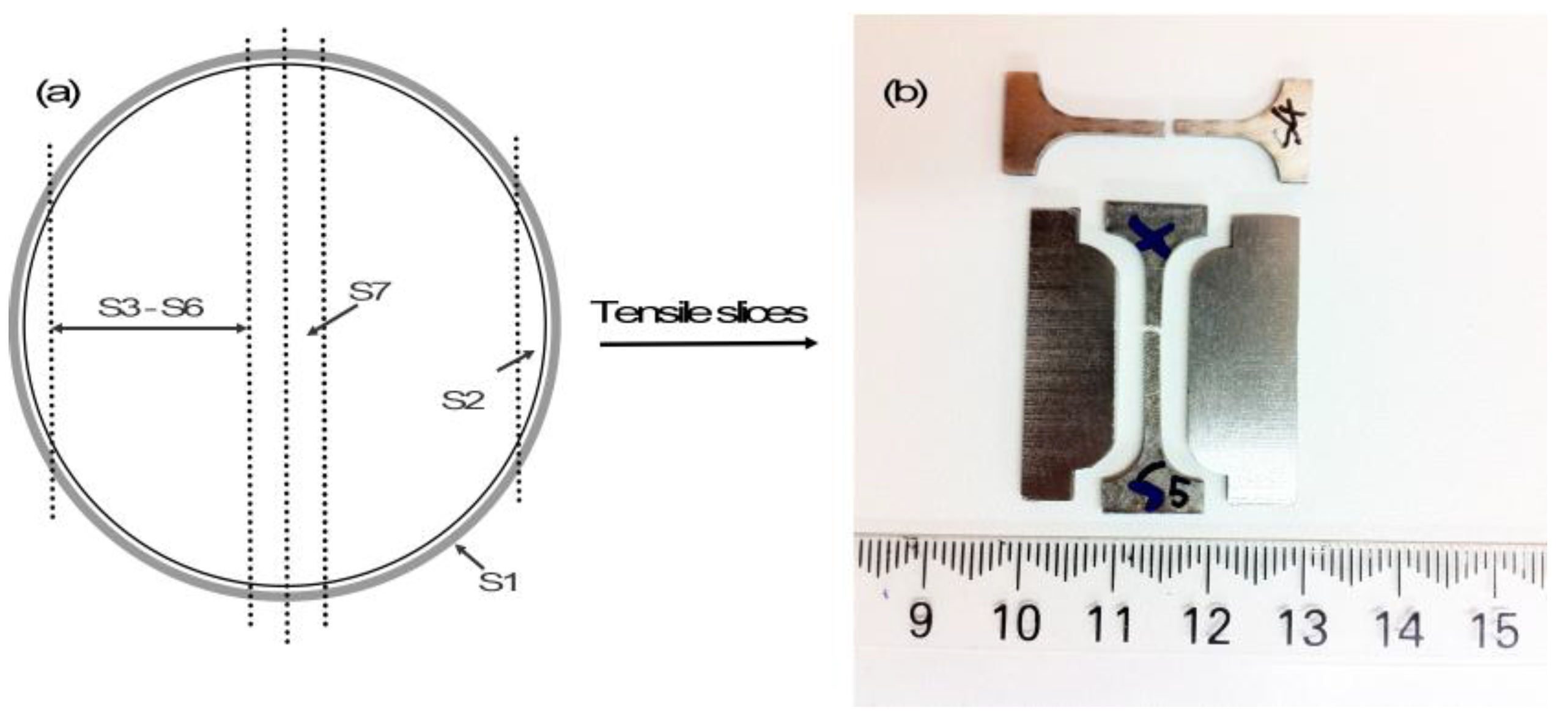
2.3. Mechanical Testing

Tensile slices were cut from the as-sintered large cylinder after removal of the contaminated scale, as shown in Figure 1. The contaminated scale layer is designated as S1 and this porous scale contains many cracks and can be easily removed to expose the interior bulk titanium. The S2 specimen cut 1.5 mm beneath the surface scale contains visible pores and is believed to contain too high impurity levels and therefore is not suitable for tensile testing. The slices S3 to S7 do not have visible pores with naked eyes and were then further machined into standard tensile specimens (~2 mm × 2 mm cross-section, 16 mm shoulder-to-shoulder length, and 10 mm gauge length). Tensile testing was performed on an Instron 3367 machine (Instron, Norwood, MA, USA) with a crosshead speed of 0.1 mm·min−1 (initial strain rate: 1.67 × 10⁻⁴ s−1). The precise displacement was determined using an extensometer with a gauge length of 8 mm (model: 2630-120, Instron Co., Norwood, MA, USA).

3. Results

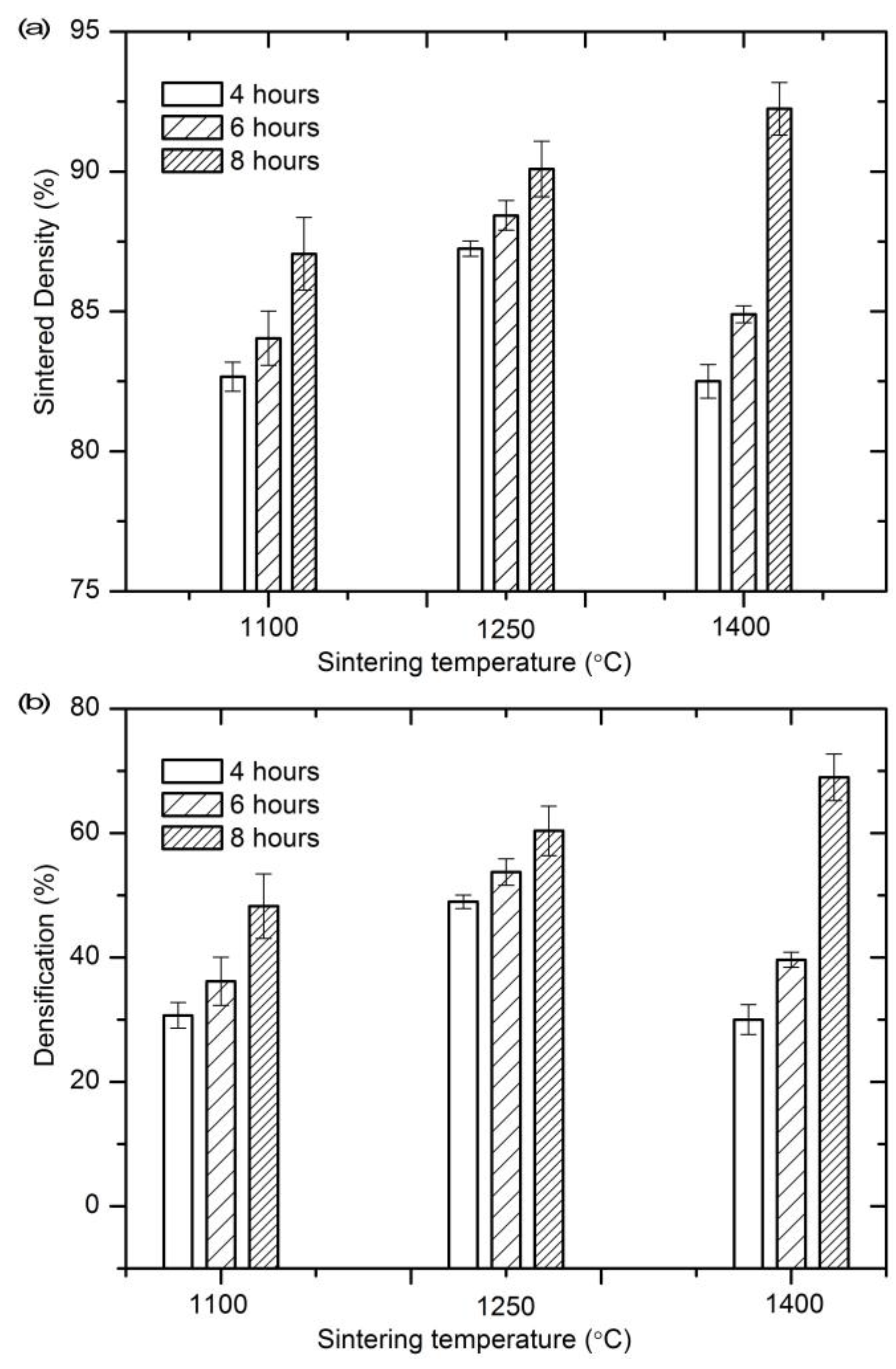
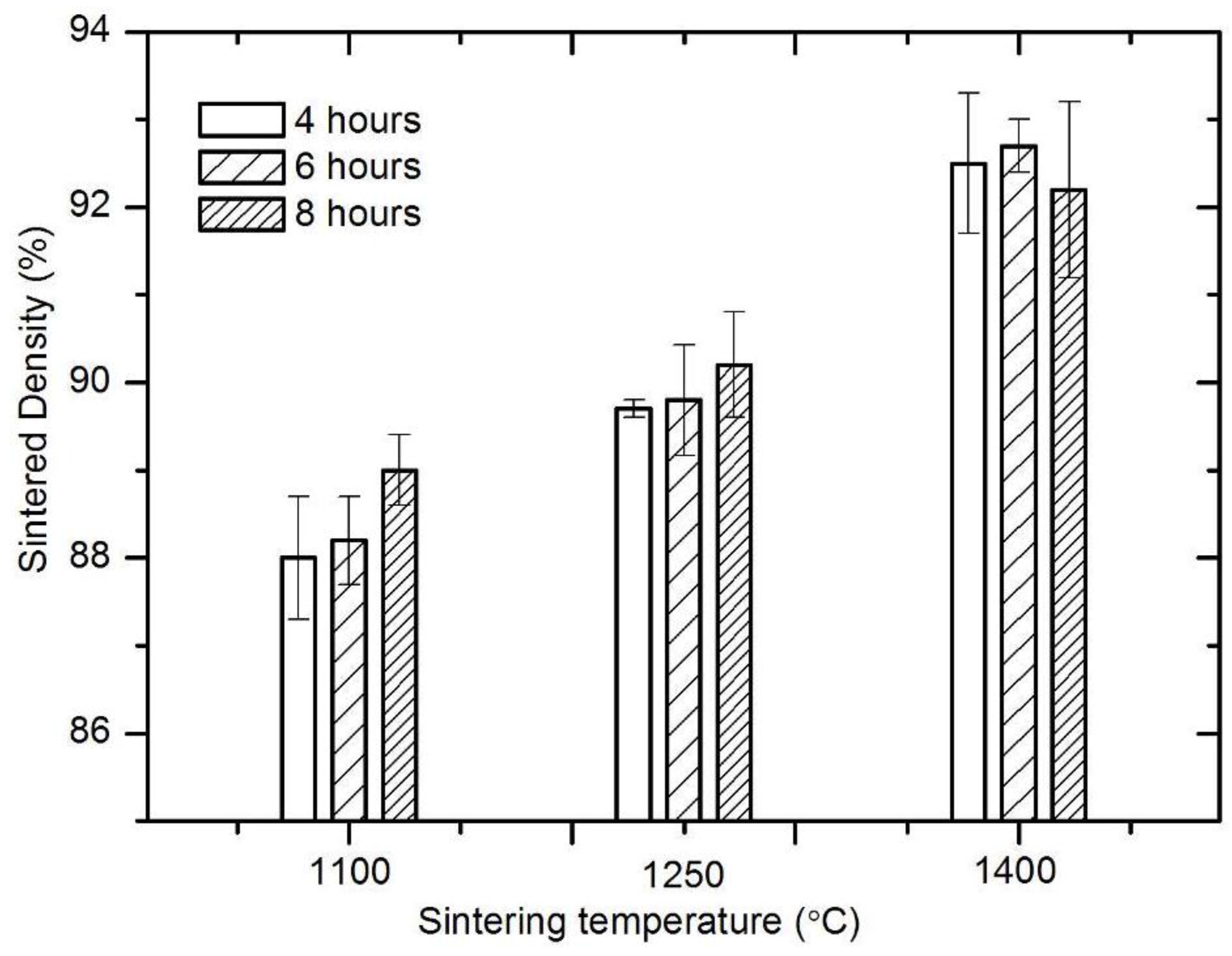
3.1. Sintering Densification

The sintered density (relative to theoretical density) and densification parameter are illustrated in Figure 2, as a function of sintering temperature and holding time. Densification parameter, ϕ, is calculated according to Equation (1) [23]
ϕ = ( ρ s ρ g ) / ( ρ t h ρ g )
where ρs, ρg and ρth are sintered density, green density and theoretical density, respectively. The value of ϕ represents how much porosity in the green compact has been removed by sintering. In general, the sintered densities in all small samples (i.e., the 12 mm-in-diameter samples) were low and in the range of 82.5% to 92.5% of theoretical density (see Figure 2a). A higher sintering temperature and/or longer hold increased the sintered density and densification (Figure 2b). However, it must be noted that the density was measured by weighing the entire sintered compact and therefore included the contaminated porous surface scale.

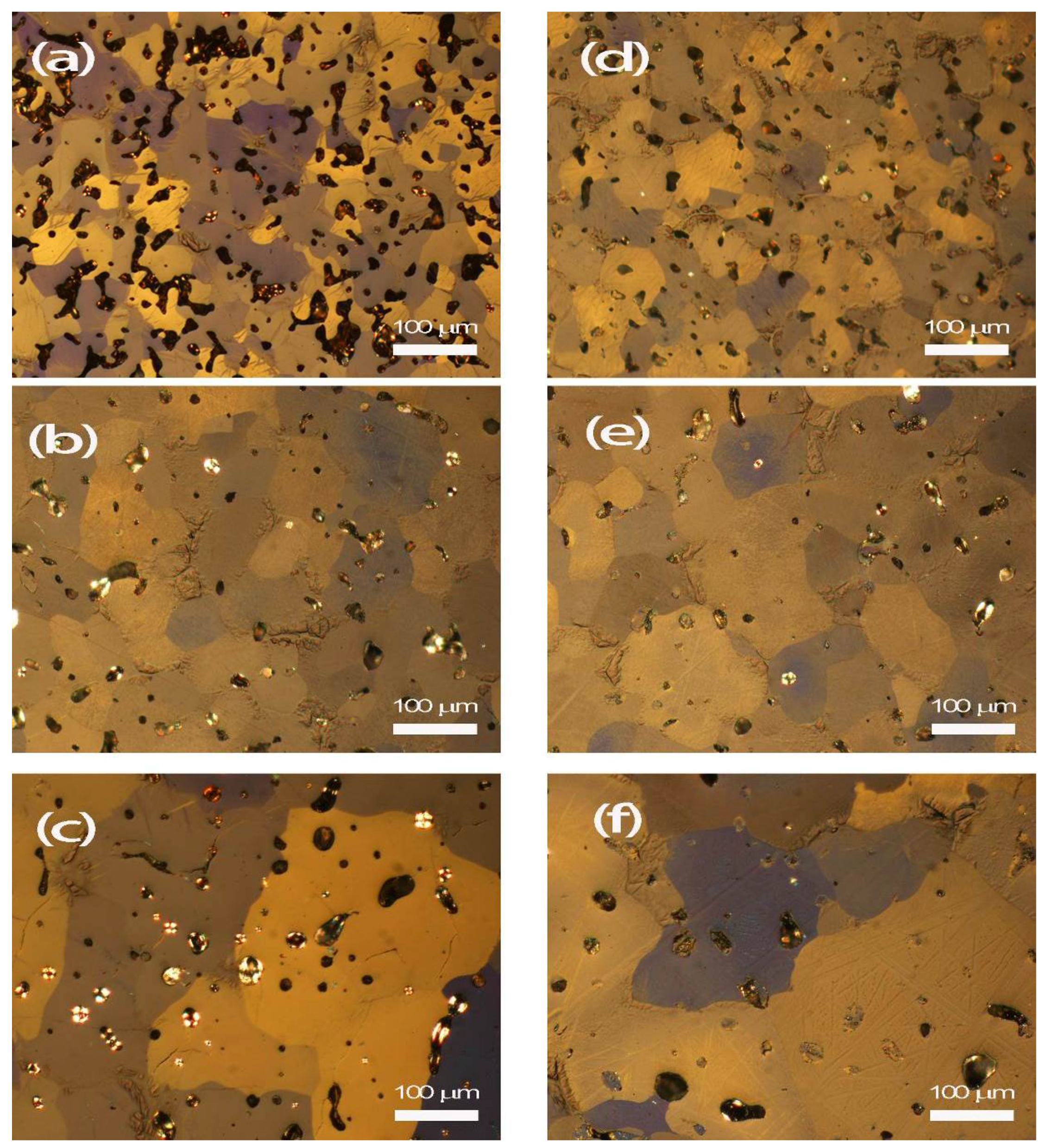
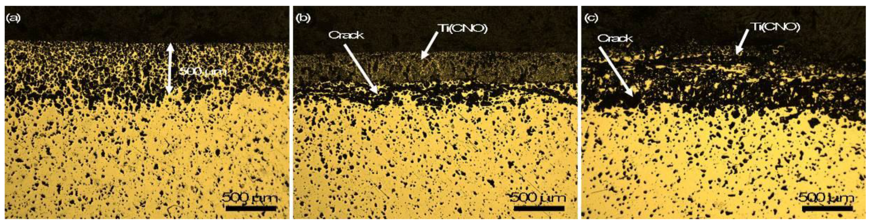
3.2. Microstructural Observation

Figure 3 presents an example of the compacts sintered at the three temperatures for 4 h. The metallographic observations of the cross sections of these compacts clearly show a fairly thick contamination scale on the compact surface. This porous layer was 300–500 µm thick, regardless of the sintering temperature. Separation between this layer and the remaining compact is visible. XRD and EDS analyses suggest that this layer is Ti(CNO) [21] and the formation mechanism will be discussed in subsequent Section 4.2.
The microstructures in the interior of the sintered compacts were observed after the outermost layer was removed. Under the polarized light microscope, macropores were evident in all the cases, as shown in Figure 4. The pore size and morphology are dependent on the sintering temperature. For instance, after being sintered at 1100 °C for 4 h, the pore shape is irregular and interconnected. This implies that, under this sintering condition, the compact might be still in the early stage of densification (Figure 4a). By increasing the holding time to 8 h, the number and size of pores decreased, although the majority of pores was still of irregular shape (Figure 4d). Pore spheroidizing occurred at higher sintering temperatures of 1250 and 1400 °C, in which cases the pores were spherical and isolated. Sintering at 1250 °C led to most pores being located either along grain boundaries or at the triple junctions (Figure 4b). At 1400 °C, some of these pores became trapped within grains as a result of grain growth in the later stages of sintering (Figure 4c). In addition to the pore morphology, the pore size is also related to the sintering conditions. The compact sintered at 1250 °C for 4 h contained pores of typically 20–40 μm in size (Figure 4b). The average pore size observed in the compact sintered at 1400 °C increased to 50 µm (Figure 4c). When the holding time was increased to 8 h, these small pores vanished and the number of pores decreased in both 1250 and 1400 °C sintered compacts (Figure 4e,f).

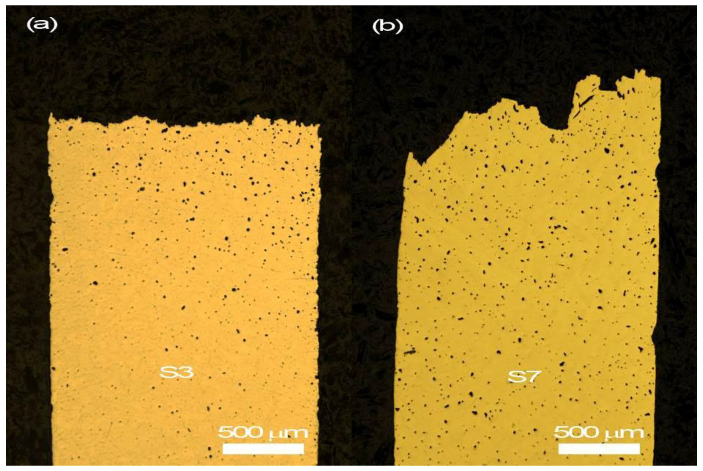
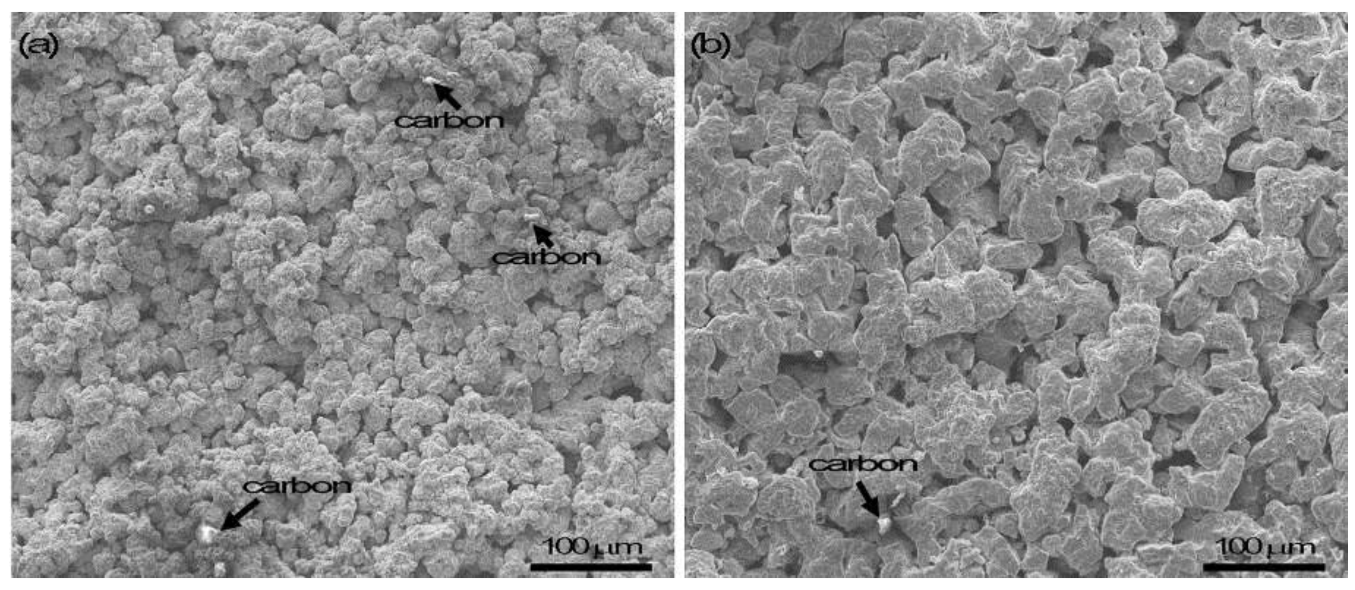
3.3. Close-Up Observation of Surface Contaminants

The surfaces of the sintered compacts, regardless of sintering temperature, show powdery morphology (Figure 5). To a much lesser content, some sinter-necks could be found. Shiny carbon particles were also visible on the sample surface. This is validated by the EDS analysis. Further evidence presented in the subsequent Section 3.4 suggests that this thick layer of surface contaminant is a compound containing Ti, C, N and O.

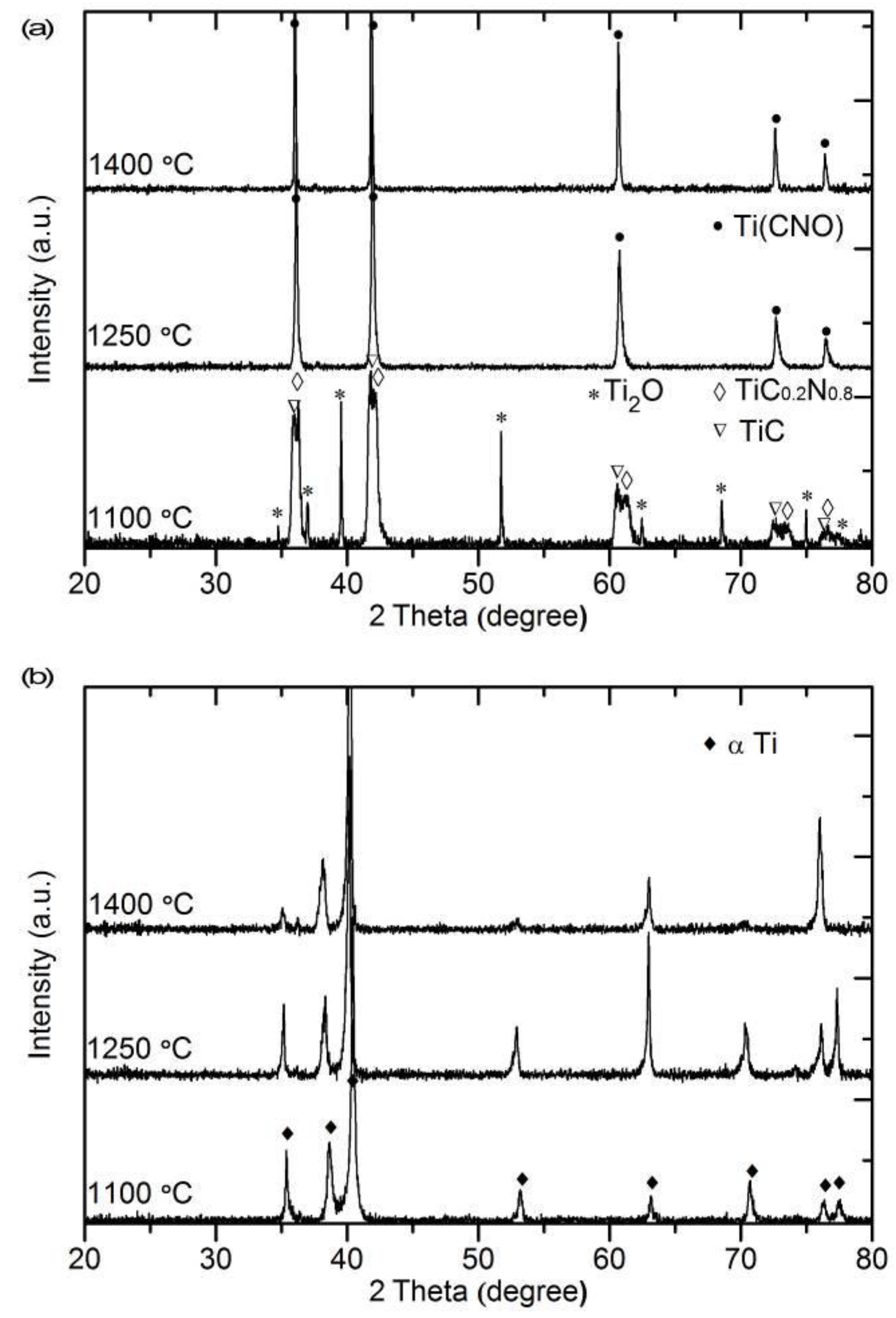
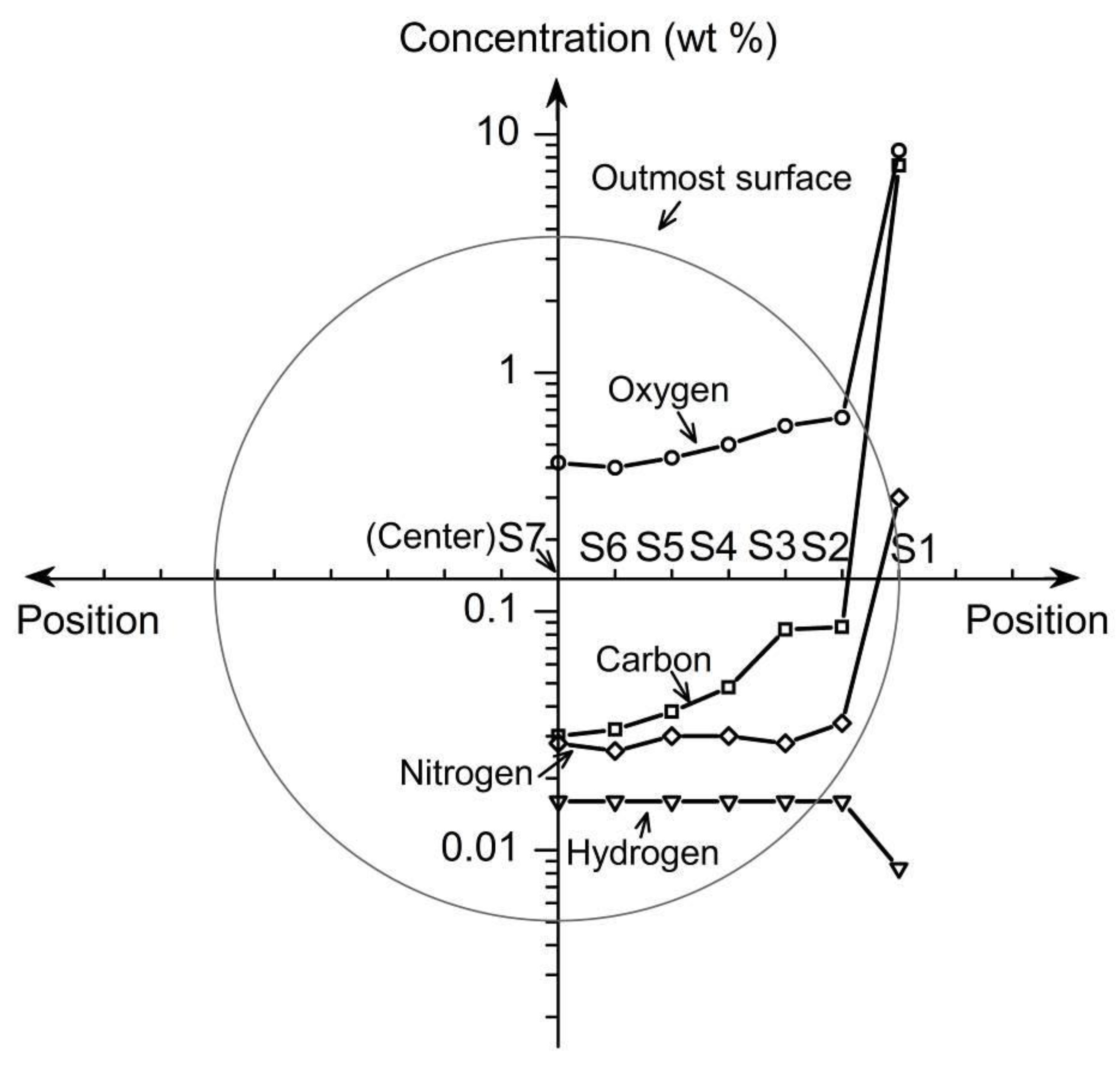
3.4. Phase Characterization of the Surface and the Interior

Figure 6 compares the XRD patterns taken from the surface and the cross section of the compact interior for samples sintered for 4 h. It is evident that the main phase constituents depend on the sintering temperature. At 1100 °C, three main phases are identified, i.e., Ti2O (JCPDS # 73-1582), TiC (JCPDS # 73-0472) and TiC0.2N0.8 (JCPDS # 76-2484), while at 1250 and 1400 °C, only Ti(C0.53N0.32O0.19) is present (JCPDS # 50-0681). In contrast, the only phase observed in the interior of samples sintered at all temperatures is α-Ti (JCPDS # 44-1294) without any other phases present.

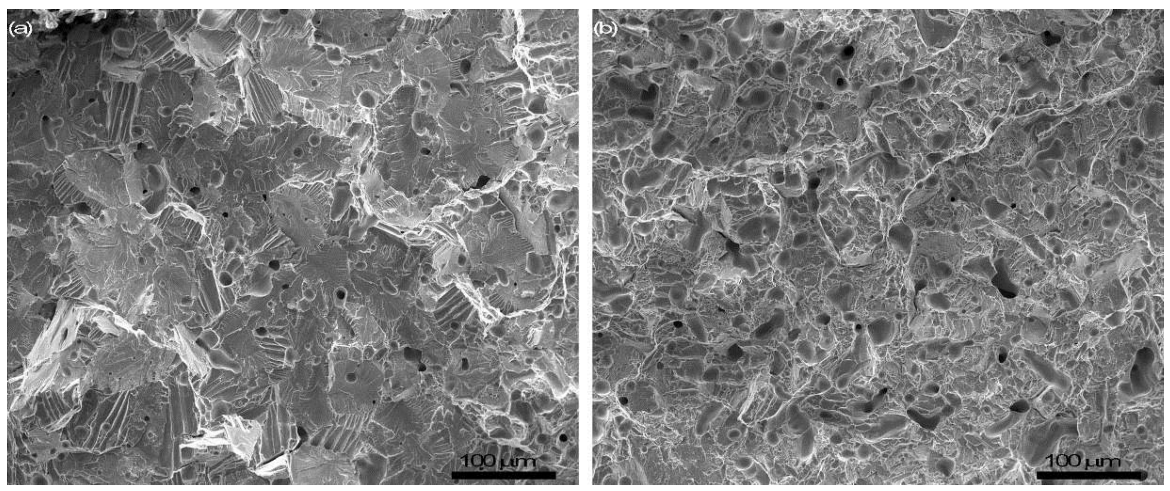
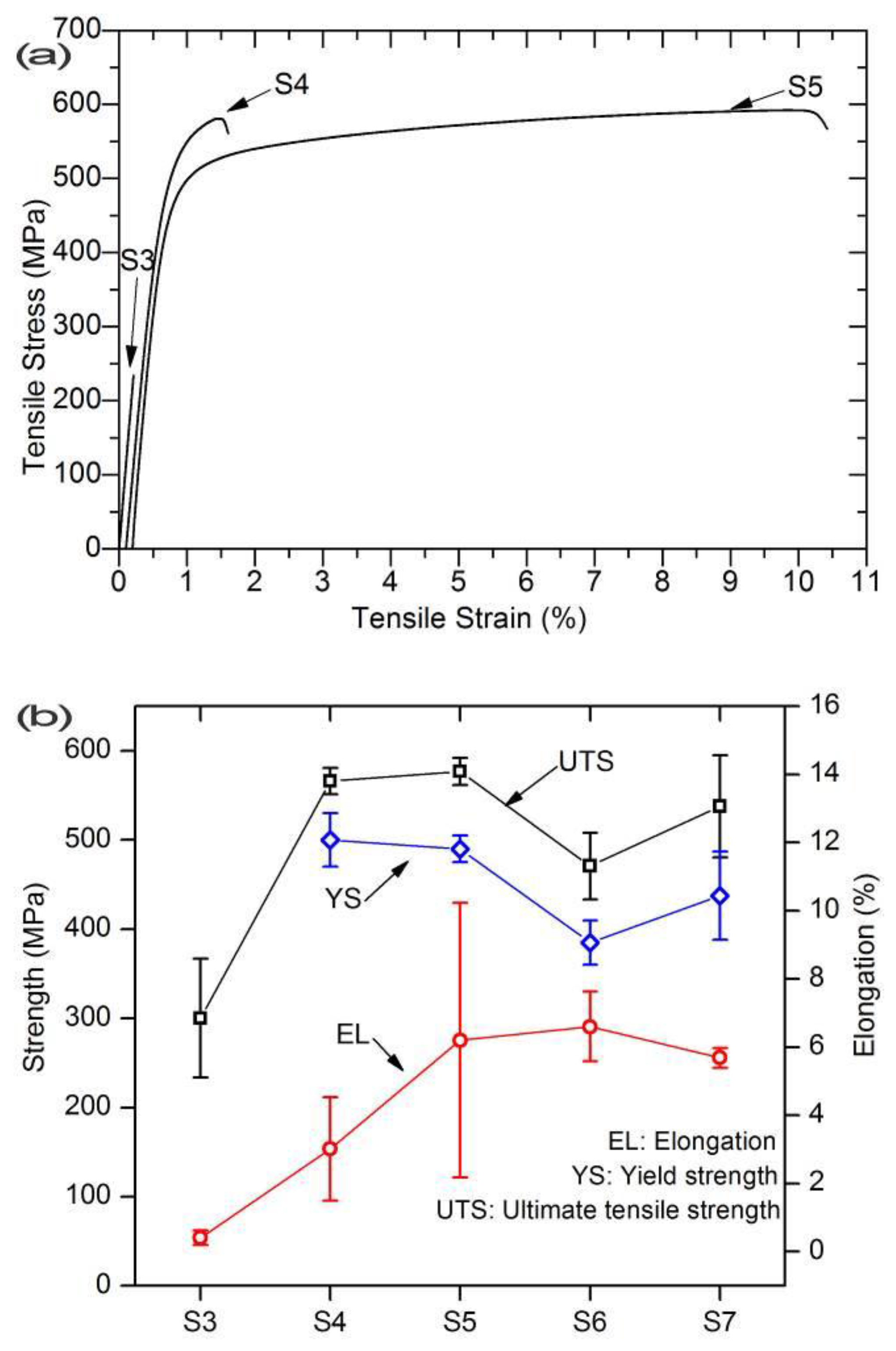
3.5. Mechanical Properties and Fractography

Typical stress–strain curves of the tensile specimens taken from three different positions in the sintered cylinder are shown in Figure 7. The contaminated surface scale was removed from the large cylinder. It is clear that specimen S3, which was taken 2 mm underneath the outermost surface, failed prior to yielding. Specimen S4 sliced 4 mm underneath the outermost surface attained a minor plastic strain of 1.5%. Specimens taken from further inside demonstrated much greater plastic strain—up to 10% for specimen S5. The average tensile properties of the specimens taken from the different positions are presented in Figure 7b. An average of ~6% plastic strain was obtained in the tensile specimens that were taken from the compact interior while a negligible plastic strain for the specimens was taken close to the contaminated surface. For the specimens taken from the interior, the yield strength (YS) was in the range of 385 to 500 MPa and ultimate tensile strength (UTS) varied from 470 to 580 MPa. In addition, the Young’s moduli of all the specimens were similar (100 to 110 GPa), which correspond to the sintered densities (95.3% to 95.9%, Table 1).
Figure 8 shows the fracture surface of the specimens S4 and S5. Smooth facets and river patterns are visible in S4 (Figure 8a), which indicate a brittle fracture mode. On the other hand, many dimples can be found in specimen S5, indicating a ductile fracture mode. Similar fracture features were observed on the fractured surface of specimens S6 and S7.

4. Discussion

4.1. Densification

As shown in Figure 2, the sintered density increases by 5%–10% with increasing of the holding time from 4 to 8 h for all three temperatures. This increase is expected because powder densification by sintering is accomplished through diffusion. For the same reason, increasing sintering temperature also results in a higher sintered density. However, as pointed out in Section 3.1, the measured sintered density does not reflect the densification level because of the presence of the porous contaminated scale. In order to evaluate the effect of temperature and holding time on densification, the contaminated surface scale should be removed before the density is measured. After removing the contaminated layer, the density of the sintered compacts is presented in Figure 9, as a function of sintering temperature and holding time. The favoring effect of increasing temperature or holding time is obvious. This is in accordance with the microstructural observations (Figure 4). Although low densities were observed in the small sintered compacts (Figure 9), the densification data of the large cylinder indicates a 96% relative density achieved after sintering at 1250 °C for 4 h (Table 2). It is noted that a sintered density ranging from 95% to 99% is common in PM Ti-6Al-4V if the blended elemental approach is used [24]. However, it needs to point out that a sintered density >98% is necessary for PM Ti products to achieve similar static property levels to wrought Ti. The use of fine particles, high compaction pressure and proper sintering conditions could readily achieve such a densification level. Such a level of densification in Ti powder products is acceptable for non-fatigue applications [4,14].

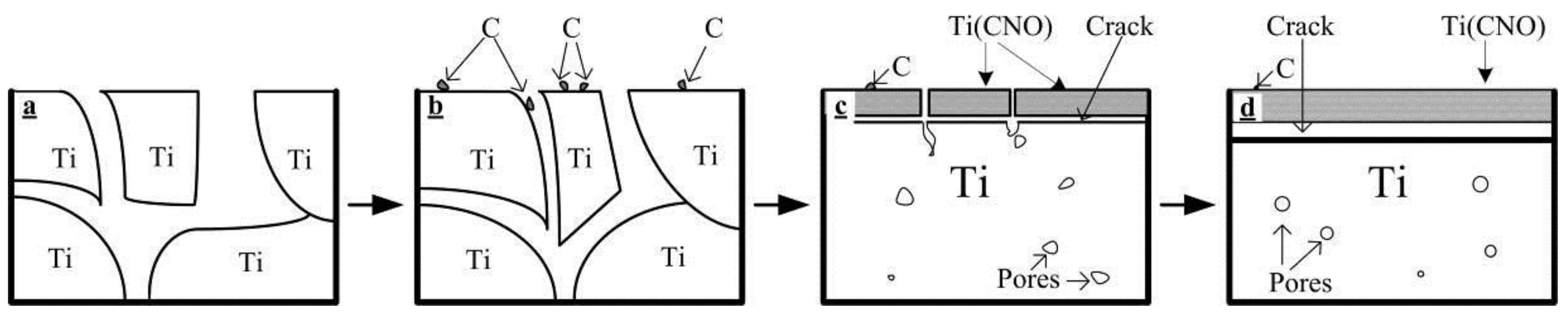
4.2. The Formation of Contaminated Surface Layer and the Effect of Interstitials on Mechanical Properties

In contrast to the sintered compact interior where only α-Ti phase is present, the surface of the sintered compact is a complex compound Ti(CNO). The carbon is thought to arise from the graphite heating elements and insulation liner material within the furnace, while nitrogen may originate from backfilled argon and oxygen from the raw powder and argon. In order to further understand the formation of the surface scale resulting from the contamination of interstitials, a formation mechanism is schematically shown in Figure 10.
Upon heating, the residual carbon in the furnace or newly evaporated carbon from the graphite heating element would deposit on the compact surface (Figure 10b) and react with Ti. Meanwhile, the oxygen and nitrogen in the backfilled argon are also involved in this reaction and, consequently, a complicated Ti(CNO) solution of TiC, TiN and TiO forms (Figure 10c). The formed Ti(CNO) film is porous. During sintering, the powder compact starts to densify and contraction occurs, which poses a significant stress between the Ti(CNO) film and the underlying Ti. The interfacial stress can also be caused by the difference in the coefficients of thermal expansion between Ti(CNO) and Ti. Such interfacial stress is the cause of the many cracks and porous structure of the Ti(CNO) compound (Figure 10d).
The formation of the Ti(CNO) compound would prevent the interior from interstitial contamination if the film were dense and intact, which is supported by a study of Lefebvre et al., who observed that the O content in Ti solid solution remained constant although the thickness of the surface oxide layer increased [25]. Unfortunately, this does not seem true in our study. Only when the residual interstitials are completely consumed or the sintering procedure is terminated does the Ti(CNO) layer stop growing. This explains a constant thickness of Ti(CNO) of approximately 300 μm regardless of sintering temperature (for the same sintering time). In other words, the outermost layer on the titanium powder compact acts as a scavenger of interstitials.
The analyses of interstitials on the transverse of the sintered compact indicate that C and O diffuse inwards, as shown in Figure 11. The observed O content at position S2 to S7 (the center) ranges from 0.7% to 0.4%. The carbon content varies from 1000 to 300 ppm. In spite of a possible scavenging effect of the outermost layer on the Ti compact, it seems impossible to avoid the inward diffusion of the interstitials. Only the very interior of the compact appears to not have been contaminated—for instance, specimens S5 and S6 in the large cylindrical compact (Figure 11).
Apparently, the measured tensile properties largely depend on the interstitials, on top of porosity, present in the specimens. Interstitials, usually represented by oxygen, can increase strength but reduce ductility dramatically [26]. It has been extensively reported that oxygen levels ~0.3 wt % significantly reduce the ductility of PM C.P. Ti to 11% from 37% at 0.07% O (with the same sintered density) [7]. A similar finding was also reported in C.P. Ti produced by metal injection moulding and sintering [27]. At the same densification level, tensile specimen S3 does not show any plastic deformation and its UTS value is also much lower than other specimens. Such poor properties are ascribable to the extremely high C (~0.1 wt %) and O content (0.6 wt %). Specimen S4, which contains 0.5% O and 0.05% C, does show a small plastic strain (average 3%, Figure 7b). On the other hand, specimen S5 contains 0.4% O and 0.04% C and therefore demonstrates much greater plastic elongation. When the other impurities are taken into account, an oxygen equivalent Oeq = O + 2N + 0.75C is usually used to reflect the effect of the interstitials [28,29]. An oxygen equivalent level higher than 0.4% for C.P. Ti is likely unacceptable. The same oxygen threshold applies for Ti-6Al-4V alloy [30]. In this present study, specimens S5 and S6 demonstrated the highest ductility, which is in accordance with their oxygen equivalents. Specimen S5 had an Oeq level of 0.47% while S4 had 0.60% oxygen equivalent. The ductility obtained in this study is in agreement with an early study by Kusaka et al. [27] who observed an elongation of ~7.0% in the as-sintered C.P. Ti that had a density of 99%. Such ductility is slightly lower than that specified in the newest ASTM B988-13 for Grade 5 PM (i.e., 9% elongation).
Although the high levels of impurities in the starting powder did not affect the densification of C.P. Ti, the resultant mechanical properties suffer significantly from the presence of these impurities. In order to mitigate the adverse effect of interstitials, not only reasonably low impurity levels are required, but also the sintering atmosphere should be controlled. It is expected that if some purifying media are placed surrounding the powder compact to be sintered, the contaminated surface could be minimized. Our additional experiments show that a contamination-free sintering could be accomplished by a proper wrapping of the Ti compact. In this separate study, we used HDH Ti powder (O: 0.29%, C: 0.04% and particle size <75 μm) as raw material and a Ti sponge as the scavenger to sinter Ti in the same graphite furnace with identical sintering parameters. The sintered Ti demonstrated an elongation of ~16%.
The fractography results (Figure 8) suggest that the fracture mode is also strongly related to the interstitials, particularly O and C. At a low level of C and O, the sintered Ti-6Al-4V fails through microvoid nucleation, growth and coalescence, which results in a typical dimple rupture. However, at a high level of C and O, the sintered Ti-6Al-4V fails via cleavage and an intergranular fracture mode. Macroscopically, a fracture at 45° with respect to the tension axis was observed in a relatively low-interstitial specimen (S7, Figure 12b), whereas a flat (0°) rupture was observed in a high-interstitial specimen (S3, Figure 12a). The critical levels seem to be 0.05% C and 0.3% to 0.4% O for the ductile-to-brittle transition. This follows the general consensus that an oxygen level >0.3% is detrimental to the ductility of the PM Ti-6Al-4V [26]. The same speculation could be also applicable to other Ti alloys, while the critical values for C and O contents might be different. It is postulated that, at different interstitial levels, the dislocation mechanisms might be different as well. Further transmission electron microscopic (TEM) investigations are necessary. In addition to the interstitial contents, the morphology and size of the pores also affect the fracture behavior. A small pore size and spherical pore shape would favor the ductile fracture mode from a fracture mechanics point of view.

5. Conclusions

This work investigated the sintering of commercially pure titanium powders in a graphite furnace backfilled with argon. A complex compound Ti(CNO) was formed on the surface with a thickness of 300–500 μm. The interiors of sintered specimens were pure single α-Ti phase. The formation of Ti(CNO) is caused by the residual interstitials in the furnace from the raw powder and in the argon gas used for backfilling. Densification was enhanced by increasing sintering temperature and/or holding time. Tensile properties were largely determined by the interstitial contents for samples where the sintered density reached at least 96%. With 0.04% C and 0.4% O contents, the sintered Ti shows an average of 6% elongation with yield strength of 385 to 490 MPa. On the other hand, for the sintered specimens containing higher C and O contents, the ductility was significantly reduced. The critical level of C and O content for ductile-to-brittle transition appeared to be ~0.04% C and 0.3% to 0.4% O. This work indicates that it is feasible to realize isothermal atmospheric sintering of C.P. HDH titanium powders in argon atmosphere in a graphite furnace and satisfactory mechanical properties can be achieved.

Acknowledgments

This work was financially supported by the Ministry of Business, Innovation and Employment (MBIE), New Zealand.

Author Contributions

Changzhou Yu conducted experimental work as part of his Ph.D project. He also analyzed the data. Peng Cao conceived and co-designed the experiments, analyzed the data and revised the manuscript. Mark Ian Jones discussed the results and revised the manuscript. Mark Ian Jones and Peng Cao were the supervisors of Changzhou Yu.

Conflicts of Interest

The authors declare no conflict of interest. The founding sponsors had no role in the design of the study; in the collection, analyses, or interpretation of data; in the writing of the manuscript, and in the decision to publish the results.

References

  1. Donachie, J.M.J. Titanium—A Technical Guide, 2nd ed.; ASM International: Materials Park, OH, USA, 2000. [Google Scholar]
  2. Froes, F.H. Titanium—Physical Metallurgy, Processing, and Applications; ASM International: Materials Park, OH, USA, 2015. [Google Scholar]
  3. Zhang, L.-C.; Attar, H. Selective Laser Melting of Titanium Alloys and Titanium Matrix Composites for Biomedical Applications: A Review. Adv. Eng. Mater. 2016, 18, 463–475. [Google Scholar] [CrossRef]
  4. Abkowitz, S.; Rowell, D. Superior Fatigue Properties for Blended Elemental P/M Ti-6Al-4V. JOM 1986, 38, 36–39. [Google Scholar] [CrossRef]
  5. Henriques, V.A.R.; Galvani, E.T.; Petroni, S.L.G.; Paula, M.S.M.; Lemos, T.G. Production of Ti-13Nb-13Zr alloy for surgical implants by powder metallurgy. J. Mater. Sci. 2010, 45, 5844–5850. [Google Scholar] [CrossRef]
  6. Whittaker, P. Dynamet Technology Approved by Boeing as Qualified Supplier for Powder Metallurgy Titanium Alloy Products. Available online: http://www.pm-review.com/dynamet-technology-approved-by-boeing-as-qualified-supplier-for-powder-metallurgy-titanium-alloy-products/ (accessed on 22 January 2017).
  7. Qian, M. Cold compaction and sintering of titanium and its alloys for near-net-shape or preform fabrication. Int. J. Powder Metall. 2010, 46, 29–44. [Google Scholar]
  8. Bolzoni, L.; Esteban, P.G.; Ruiz-Navas, E.M.; Gordo, E. Mechanical behaviour of pressed and sintered titanium alloys obtained from prealloyed and blended elemental powders. J. Mech. Behav. Biomed. Mater. 2012, 14, 29–38. [Google Scholar] [CrossRef] [PubMed] [Green Version]
  9. Fujita, T.; Ogawa, A.; Ouchi, C.; Tajima, H. Microstructure and properties of titanium alloy produced in the newly developed blended elemental powder metallurgy process. Mater. Sci. Eng. A 1996, 213, 148–153. [Google Scholar] [CrossRef]
  10. Yang, Y.F.; Luo, S.D.; Bettles, C.J.; Schaffer, G.B.; Qian, M. The effect of Si additions on the sintering and sintered microstructure and mechanical properties of Ti-3Ni alloy. Mater. Sci. Eng. A 2011, 528, 7381–7387. [Google Scholar] [CrossRef]
  11. Yang, Y.F.; Luo, S.D.; Schaffer, G.B.; Qian, M. The Sintering, Sintered Microstructure and Mechanical Properties of Ti-Fe-Si Alloys. Metall. Mater. Trans. A 2012, 43, 4896–4906. [Google Scholar] [CrossRef] [Green Version]
  12. Xu, Q.; Gabbitas, B.; Matthews, S.; Zhang, D. The development of porous titanium products using slip casting. J. Mater. Process. Technol. 2013, 213, 1440–1446. [Google Scholar] [CrossRef]
  13. Kroll, W. Malleable Alloys of Titanium. Z. Metall. 1937, 29, 189–192. [Google Scholar]
  14. Qian, M.; Schaffer, G.B.; Bettles, C.J. Sintering of Titanium and its Alloys, in Sintering of Advanced Materials: Fundamentals and Processes; Fang, Z.Z., Ed.; Woodhead Publishing: Philadelphia, PA, USA, 2010; pp. 324–355. [Google Scholar]
  15. Dean, R.S.; Wartman, F.S.; Hayes, E.T. Ductile Titanium—Its Fabrication and Physical Properties. Trans. Am. Inst. Mining Met. Eng. 1946, 166, 381–389. [Google Scholar]
  16. Limberg, W.; Ebel, T.; Pyczak, F.; Schimansky, F.P. Influence of the sintering atmosphere on the tensile properties of MIM-processed Ti 45Al 5Nb 0.2B 0.2C. Mater. Sci. Eng. A 2012, 552, 323–329. [Google Scholar] [CrossRef]
  17. Arensburger, D.S.; Pugin, V.S.; Fedorchenko, I.M. Properties of electrolytic and reduced titanium powders and sinterability of porous compacts from such powders. Sov. Powder Metall. Met. Ceram. 1968, 7, 362–367. [Google Scholar] [CrossRef]
  18. Heaney, D.F.; German, R.M. Proceedings of PM 2004 Powder Metallurgy World Congress; European Powder Metallurgy Association: Vienna, Austria, 2004; pp. 222–227. [Google Scholar]
  19. Kanto Yakin Kogyo Co. Available online: http://www.k-y-k.co.jp/en/product01.html (accessed on 22 January 2017).
  20. Metal Powder Reports. Furnace Masters Difficult Metals. Met. Powder Rep. 2004, 59, 12. [Google Scholar]
  21. Yu, C.; Cao, P.; Jones, M.I. Effect of Contaminants on Sintering of Ti and Ti-6Al-4V Alloy Powders in an Argon-Back-Filled Graphite Furnace. Key Eng. Mater. 2012, 520, 139–144. [Google Scholar] [CrossRef]
  22. Yu, C.Z.; Jones, M.I. Investigation of chloride impurities in hydrogenated–dehydrogenated Kroll processed titanium powders. Powder Metall. 2013, 56, 304–309. [Google Scholar] [CrossRef]
  23. German, R.M. Sintering Theory and Practice; Wiley: New York, NY, USA, 1996. [Google Scholar]
  24. Hausner, H.H.; Smith, G.D.; Antes, H.W. Modern Development in Powder Metallurgy, Volume 13: Ferrous and Nonferrrous Materials; Metal Powder Industries Federation: Prinston, NJ, USA, 1981; pp. 537–549. [Google Scholar]
  25. Lefebvre, L.P.; Baril, E. Effect of Oxygen Concentration and Distribution on the Compression Properties on Titanium Foams. Adv. Eng. Mater. 2008, 10, 868–876. [Google Scholar] [CrossRef] [Green Version]
  26. Conrad, H. Effect of interstitial solutes on the strength and ductility of titanium. Prog. Mater Sci. 1981, 26, 123–403. [Google Scholar] [CrossRef]
  27. Kusaka, K.; Kohno, T.; Kondo, T.; Horata, A. Tensile Behavior of Sintered Titanium by MIM Process. J. Jpn. Soc. Powder Powder Metall. 1995, 42, 383–387. [Google Scholar] [CrossRef]
  28. Conrad, H. The rate controlling mechanism during yielding and flow of α-titanium at temperatures below 0.4 TM. Acta Metall. 1966, 14, 1631–1633. [Google Scholar] [CrossRef]
  29. Okazaki, K.; Conrad, H. Effects of interstitial content and grain size on the strength of titanium at low temperatures. Acta Metall. 1973, 21, 1117–1129. [Google Scholar] [CrossRef]
  30. Wang, H.; Fang, Z.Z.; Sun, P. A critical review of mechanical properties of powder metallurgy titanium. Int. J. Powder Metall. 2010, 46, 45–57. [Google Scholar]
Figure 1. (a) Schematic illustration of the cylinder and the seven slices cut from the cylinder, only slices S3 to S7 were further machined for tensile test and (b) the tensile specimens after fracture. S1 was the outer scale, S2 to S7 were the slices cut from outer slice to the interior slices. S7 slices were cut from the central of the sintered large cylinder.
Metals 07 00067 g001
Figure 2. Effects of sintering temperature and holding time on relative sintered density (a) and densification parameter (b).
Metals 07 00067 g002
Figure 3. Micrographs of the cross-sections of sintered small compacts at different sintering temperatures: (a) 1100 °C; (b) 1250 °C; and (c) 1400 °C. All compacts were sintered for 4 h at the respective temperature.
Metals 07 00067 g003
Figure 4. Microstructure of the cross sections of sintered small compacts at various sintering conditions. The micrographs were taken under polarized light microscopy. The compacts were sintered at various temperatures for different holding times: (a) 1100 °C/4 h; (b) 1250 °C/4 h; (c) 1400 °C/4 h; (d) 1100 °C/8 h; (e) 1250 °C/8 h; and (f) 1250 °C/8 h.
Metals 07 00067 g004
Figure 5. Surface morphologies of the small compacts sintered at 1250 °C (a) and 1400 °C (b), respectively. Sintering time was 4 h.
Metals 07 00067 g005
Figure 6. X-ray diffraction (XRD) patterns of the as-sintered small Ti compacts (a) on the surface and (b) cross-sections of compact interior. The compact was sintered for 4 h at 1100, 1250 and 1400 °C, respectively.
Metals 07 00067 g006
Figure 7. (a) Representative engineering stress-strain curves and (b) a summary of tensile mechanical properties for slices cut from different positions of the sintered cylinder.
Metals 07 00067 g007
Figure 8. Fracture surfaces of tensile slices from sintered titanium samples: (a) S4 and (b) S5.
Metals 07 00067 g008
Figure 9. Relative sintered densities of compacts after removing contaminated scale.
Metals 07 00067 g009
Figure 10. Schematic of the formation process of the contaminated scale. (a) Starting powder compact; (b) contaminants such as C are deposited on the Ti powder particles; (c) Ti reacts with the contaminants forming Ti(CNO). Cracking occurs as a result of different coefficients of thermal expansion; (d) larger cracks and more pores are formed at a higher temperature.
Metals 07 00067 g010
Figure 11. The distribution of interstitial contents at varied slices taken from different positions. Superimposed is the contour of the cylindrical compact.
Metals 07 00067 g011
Figure 12. Macroscopic fracture surface of the tensile specimens (a) S3 and (b) S7.
Metals 07 00067 g012
Table 1. Sintered density in terms of percentage of theoretical density for slices taken from the large cylinder.
SlicesS3S4S5S6S7
Sintered density (%)95.7 ± 0.195.6 ± 0.395.9 ± 1.095.3 ± 0.195.8 ± 0.2
Table 2. Densities and densification level for large cylinder prepared for tensile testing. CIP: Cold isostatic pressing.
SpecimenGreen Density (600 MPa CIP, %)Sintered Density (%)Densification (%)
Cylinder87.095.8.69.2

