
Finite Element Based Physical Chemical Modeling of Corrosion in Magnesium Alloys

Abstract
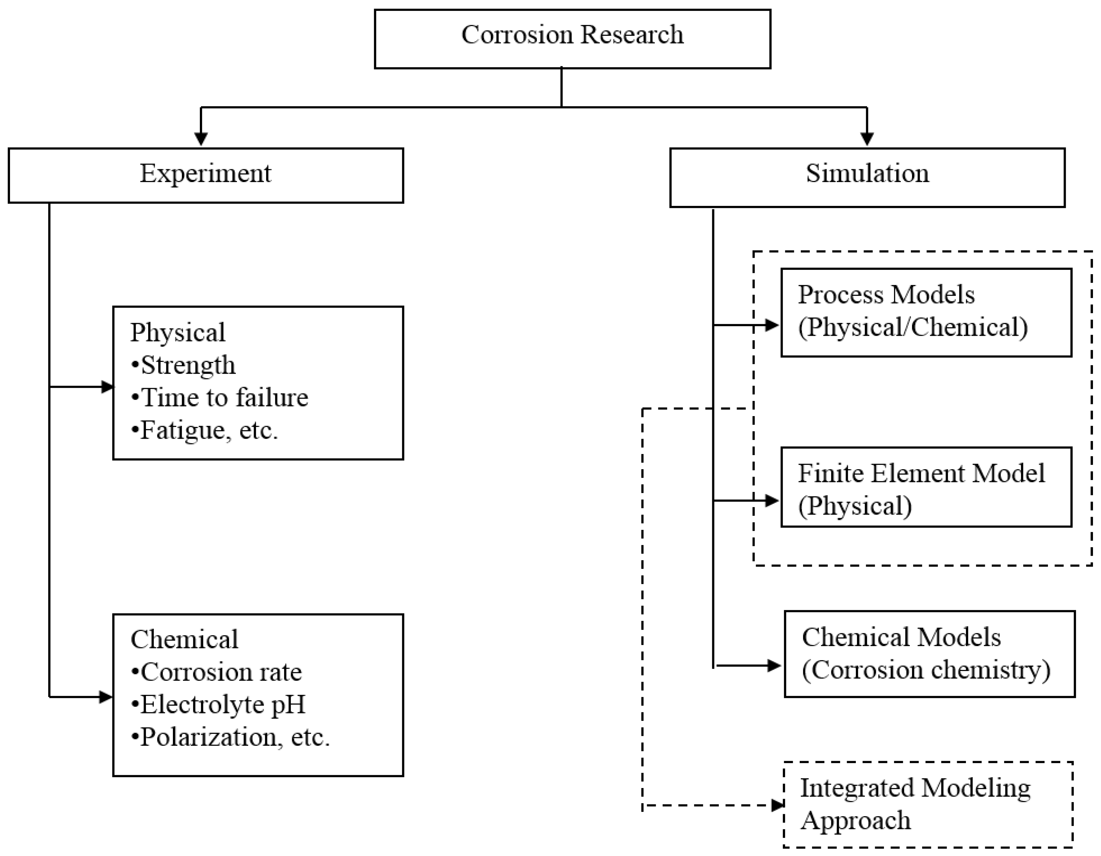
:1. Introduction
2. Finite Element Modeling of Corroded AZ31 Alloy
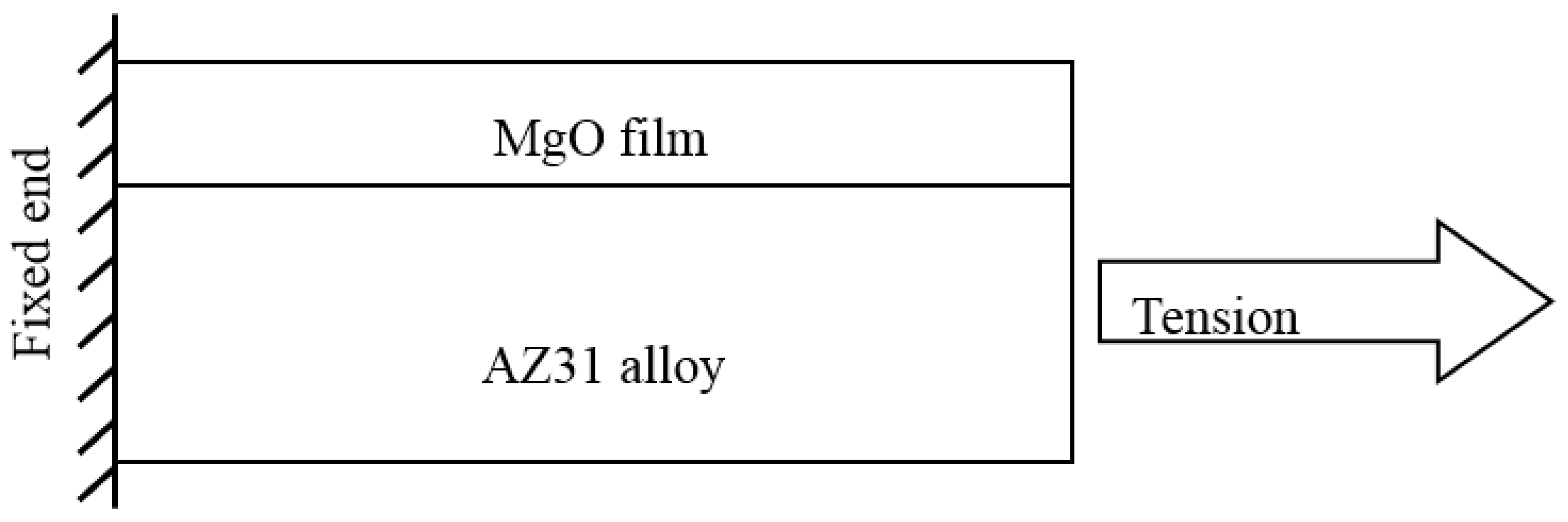
2.1. Geometry Description and Boundary Conditions
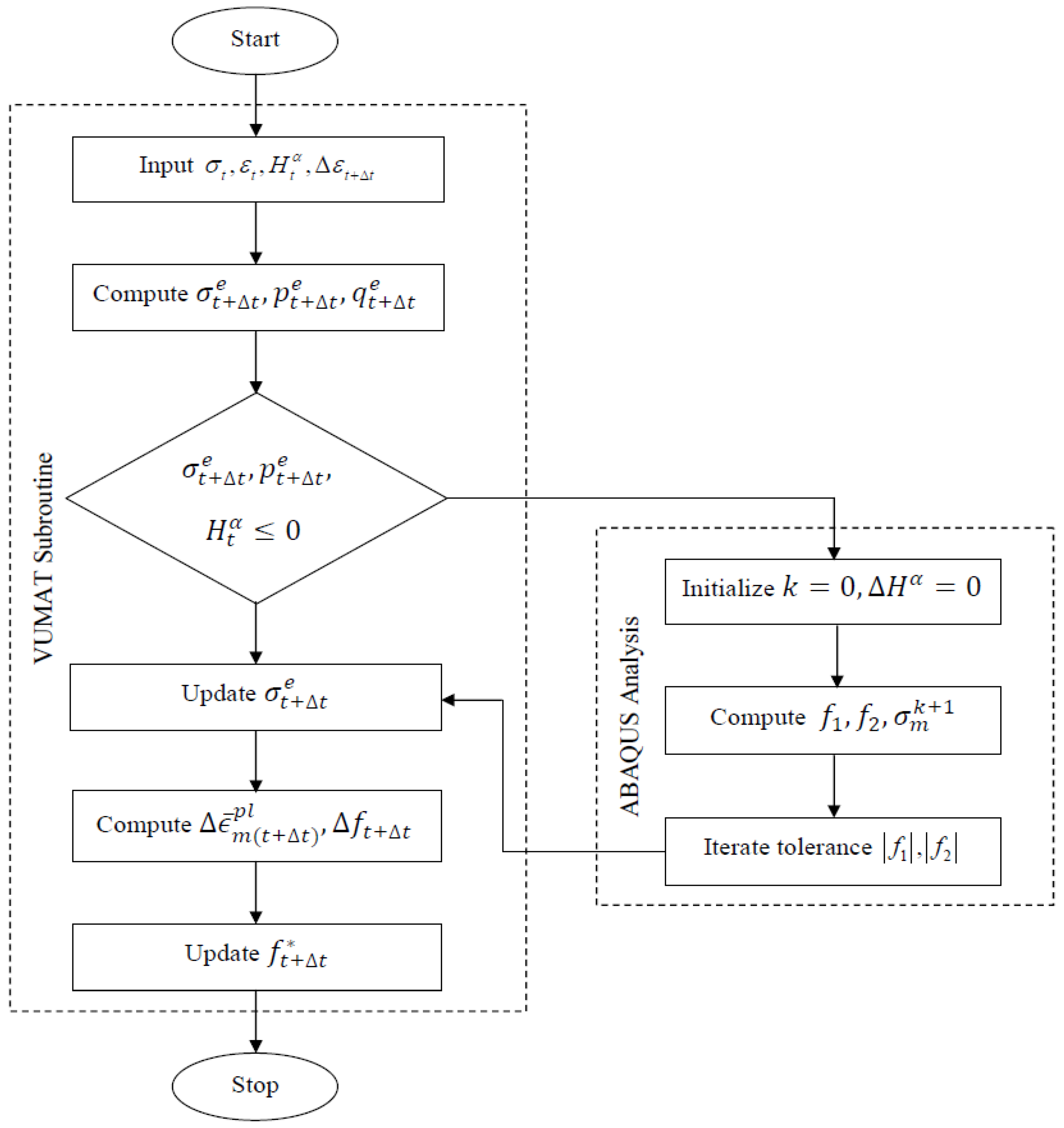
2.2. Constitutive Modeling of Voids in AZ31 under Corrosion
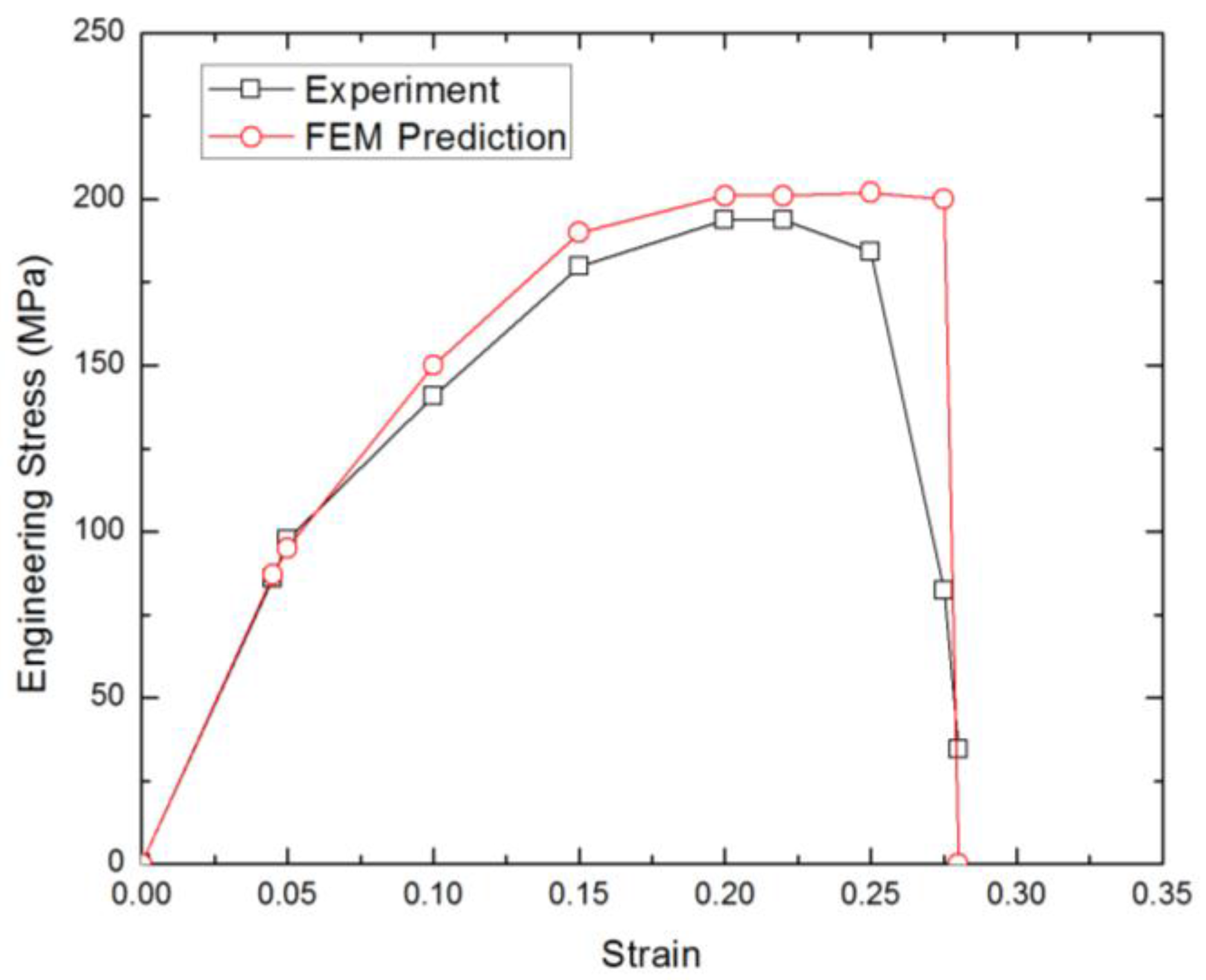
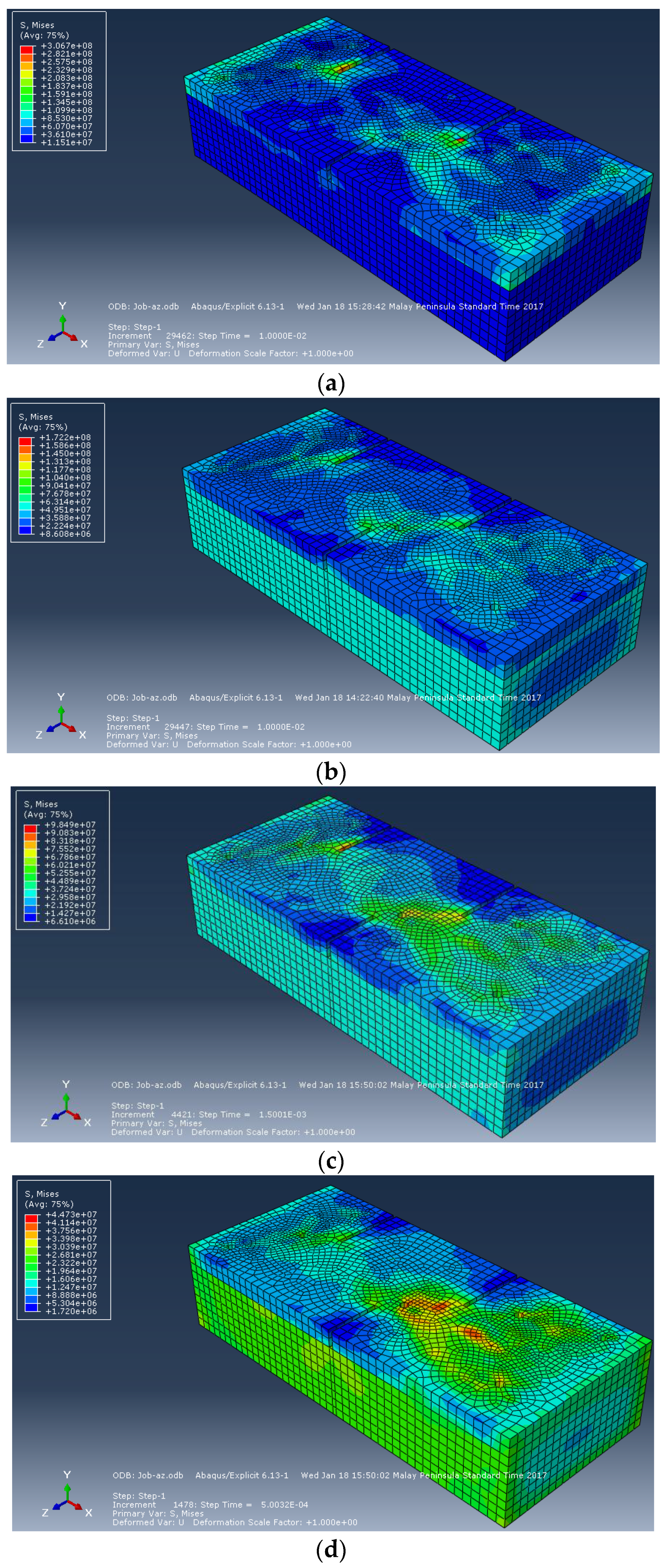
2.3. Validation of Finite Element Model
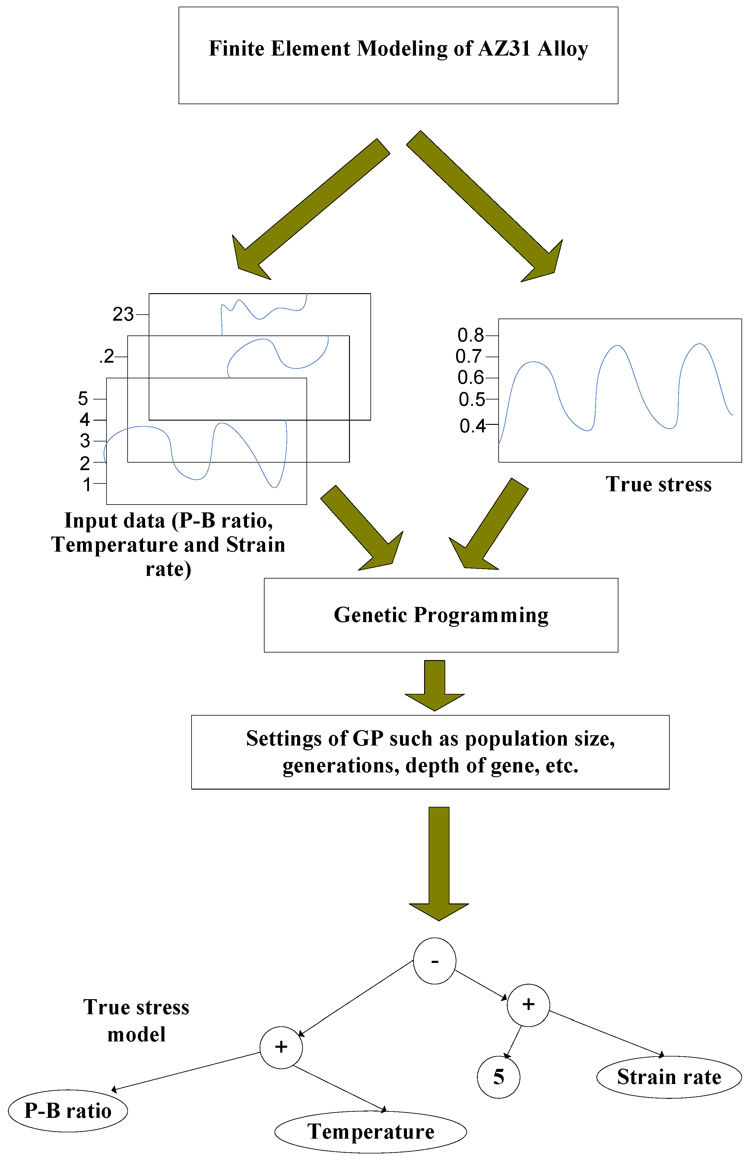
3. Analytical Modeling of Stress Corrosion Characteristics of AZ31 Alloy
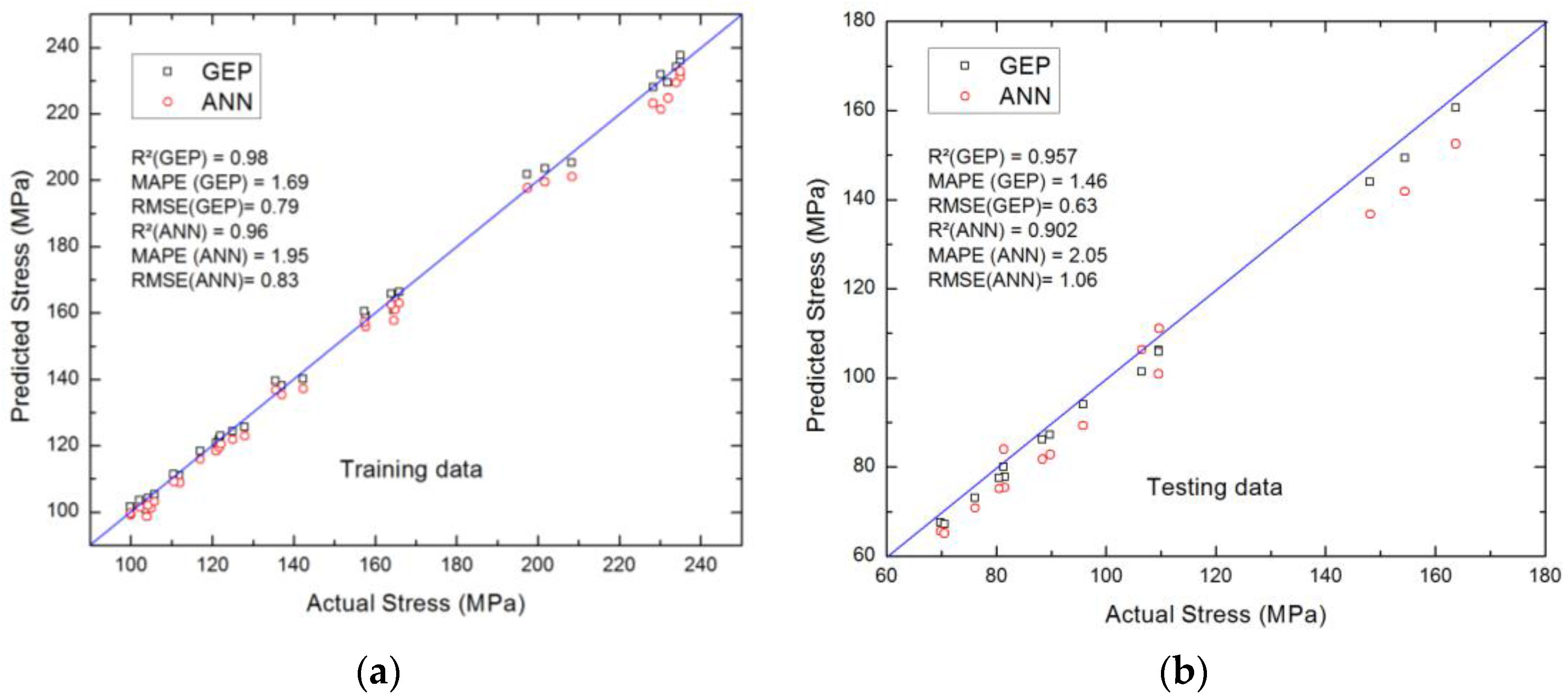
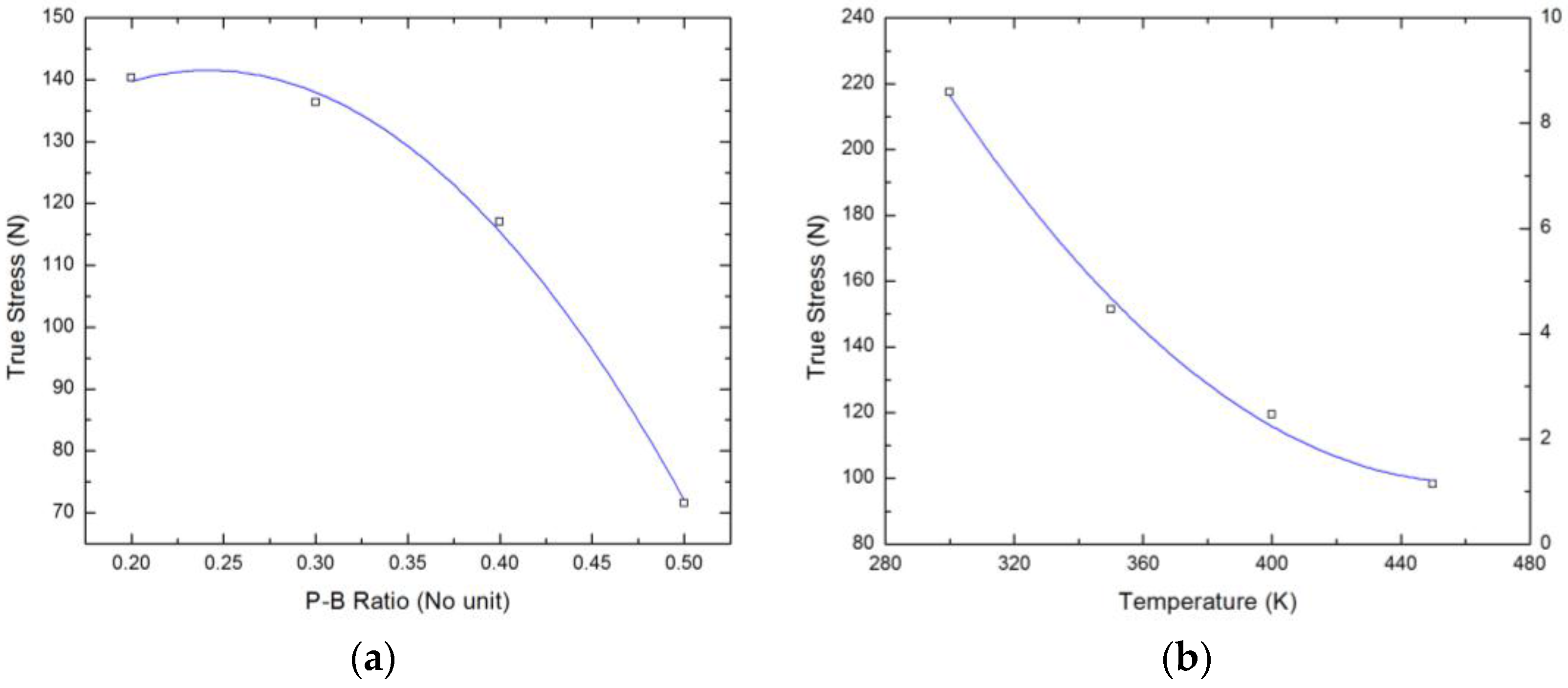
3.1. Performance Evaluation of the Analytical Model
3.2. Model Analysis Based on Corrosion Physics
4. Conclusions
Author Contributions
Conflicts of Interest
References
- Çelik, İ. Structure and surface properties of Al2O3–TiO2 ceramic coated AZ31 magnesium alloy. Ceram. Int. 2016, 42, 13659–13663. [Google Scholar] [CrossRef]
- Lentz, M.; Risse, M.; Schaefer, N.; Reimers, W.; Beyerlein, I.J. Strength and ductility with {1011}-{1012} double twinning in a magnesium alloy. Nat. Commun. 2016, 7, 11068. [Google Scholar] [CrossRef] [PubMed]
- Sunil, B.R.; Reddy, G.P.K.; Patle, H.; Dumpala, R. Magnesium based surface metal matrix composites by friction stir processing. J. Magnes. Alloys 2016, 4, 52–61. [Google Scholar] [CrossRef]
- Jafari, S.; Harandi, S.E.; Raman, R.K.S. A review of stress-corrosion cracking and corrosion fatigue of magnesium alloys for biodegradable implant applications. JOM 2015, 67, 1143–1153. [Google Scholar] [CrossRef]
- Jafari, S.; Raman, R.K.S.; Davies, C.H.J. Corrosion fatigue of a magnesium alloy in modified simulated body fluid. Eng. Fract. Mech. 2015, 137, 2–11. [Google Scholar] [CrossRef]
- Raman, R.K.S.; Harandi, S.E. Understanding corrosion-assisted cracking of magnesium alloys for bioimplant applications. In Magnesium Technology; John Wiley & Sons, Inc.: Hoboken, NJ, USA, 2016. [Google Scholar]
- Raman, R.K.S.; Jafari, S.; Harandi, S.E. Corrosion fatigue fracture of magnesium alloys in bioimplant applications: A review. Eng. Fract. Mech. 2015, 137, 97–108. [Google Scholar] [CrossRef]
- Argade, G.R.; Yuan, W.; Kandasamy, K.; Mishra, R.S. Stress corrosion cracking susceptibility of ultrafine grained AZ31. J. Mater. Sci. 2012, 47, 6812–6822. [Google Scholar] [CrossRef]
- Su, Y.; Guo, Y.; Huang, Z.; Zhang, Z.; Li, G.; Lian, J.; Ren, L. Preparation and corrosion behaviors of calcium phosphate conversion coating on magnesium alloy. Surf. Coat. Technol. 2016, 307, 99–108. [Google Scholar] [CrossRef]
- Choudhary, L.; Raman, R.K.S.; Hofstetter, J.; Uggowitzer, P.J. In Vitro characterization of stress corrosion cracking of aluminium-free magnesium alloys for temporary bio-implant applications. Mater. Sci. Eng. C 2014, 42, 629–636. [Google Scholar] [CrossRef] [PubMed]
- Gaur, S.; Raman, R.K.S.; Khanna, A.S. In vitro investigation of biodegradable polymeric coating for corrosion resistance of Mg-6Zn-Ca alloy in simulated body fluid. Mater. Sci. Eng. C 2014, 42, 91–101. [Google Scholar] [CrossRef] [PubMed]
- Wei, F.; Zhang, W.; Zhang, T.; Wang, F. Effect of variations of Al content on microstructure and corrosion resistance of PEO coatings on Mg-Al alloys. J. Alloys Compd. 2017, 690, 195–205. [Google Scholar] [CrossRef]
- Grogan, J.A.; Leen, S.B.; McHugh, P.E. A physical corrosion model for bioabsorbable metal stents. Acta Biomater. 2014, 10, 2313–2322. [Google Scholar] [CrossRef] [PubMed]
- Duddu, R.; Kota, N.; Qidwai, S.M. An Extended Finite Element Method Based Approach for Modeling Crevice and Pitting Corrosion. J. Appl. Mech. Trans. ASME 2016, 83, 081005. [Google Scholar] [CrossRef]
- Shang, W.; Wang, X.; Wen, Y.; He, C.; Wang, Y.; Zhang, L.; Zhang, Z. Corrosion resistance and molecular dynamics behavior of the MAO/SAM composite coatings on magnesium alloy. Prot. Met. Phys. Chem. Surf. 2016, 52, 847–853. [Google Scholar] [CrossRef]
- Narimani, N.; Zarei, B.; Pouraliakbar, H.; Khalaj, G. Predictions of corrosion current density and potential by using chemical composition and corrosion cell characteristics in microalloyed pipeline steels. Meas. J. Int. Meas. Confed. 2015, 62, 97–107. [Google Scholar] [CrossRef]
- Zadeh Shirazi, A.; Mohammadi, Z. A hybrid intelligent model combining ANN and imperialist competitive algorithm for prediction of corrosion rate in 3C steel under seawater environment. Neur. Comput. Appl. 2016. [Google Scholar] [CrossRef]
- Zhao, P.J.; Chen, Z.H.; Dong, C.F. Failure Analysis of Warm Stamping of Magnesium Alloy Sheet Based on an Anisotropic Damage Model. J. Mater. Eng. Perform. 2014, 23, 4032–4041. [Google Scholar] [CrossRef]
- Vasilos, T.; Mitchell, J.B.; Spriggs, R.M. Mechanical Properties of Pure, Dense Magnesium Oxide as a Function of Temperature and Grain Size. J. Am. Ceram. Soc. 1964, 47, 606–610. [Google Scholar] [CrossRef]
- Acharyya, S.; Dhar, S. A complete GTN model for prediction of ductile failure of pipe. J. Mater. Sci. 2008, 43, 1897–1909. [Google Scholar] [CrossRef]
- Oh, C.S.; Kim, N.H.; Kim, Y.J.; Baek, J.H.; Kim, Y.P.; Kim, W.S. A finite element ductile failure simulation method using stress-modified fracture strain model. Eng. Fract. Mech. 2011, 78, 124–137. [Google Scholar] [CrossRef]
- Zhao, P.J.; Chen, Z.H.; Dong, C.F. Damage and Failure Analysis of AZ31 Alloy Sheet in Warm Stamping Processes. J. Mater. Eng. Perform. 2016, 25, 2702–2710. [Google Scholar] [CrossRef]
- Needleman, A.; Tvergaard, V. An analysis of dynamic, ductile crack growth in a double edge cracked specimen. Int. J. Fract. 1991, 49, 41–67. [Google Scholar] [CrossRef]
- Lin, Y.C.; Liu, Z.H.; Chen, X.M.; Chen, J. Uniaxial ratcheting and fatigue failure behaviors of hot-rolled AZ31B magnesium alloy under asymmetrical cyclic stress-controlled loadings. Mater. Sci. Eng. A 2013, 573, 234–244. [Google Scholar] [CrossRef]
- Searson, D.P.; Leahy, D.E.; Willis, M.J. GPTIPS: An Open Source Genetic Programming Toolbox for Multigene Symbolic Regression. In Proceedings of the International MultiConference of Engineers and Computer Scientists 2010 (IMECS 2010), Hong Kong, China, 17–19 March 2010.
- Vijayaraghavan, V.; Castagne, S. Computational model for predicting the effect of process parameters on surface characteristics of mass finished components. Eng. Comput. 2016, 33, 789–805. [Google Scholar] [CrossRef]


| Parameter | AZ31 Alloy | MgO Film |
|---|---|---|
| Thermal Conductivity (k) | 96 W/m-K | 42 W/m-K |
| Density (ρ) | 1770 kg/m3 | 3580 kg/m3 |
| Young’s modulus (E) | 44.8 GPa | 249 GPa |
| Poisson’s ratio (υ) | 0.35 | 0.18 |
| Specific heat (Cp) | 1000 J/kg/K | 877 J/kg/K |
| Process Input Variable | Values | Units |
|---|---|---|
| P–B ratio | 0.2, 0.3, 0.4, 0.5 | No units |
| Temperature | 300, 350, 400, 450 | K |
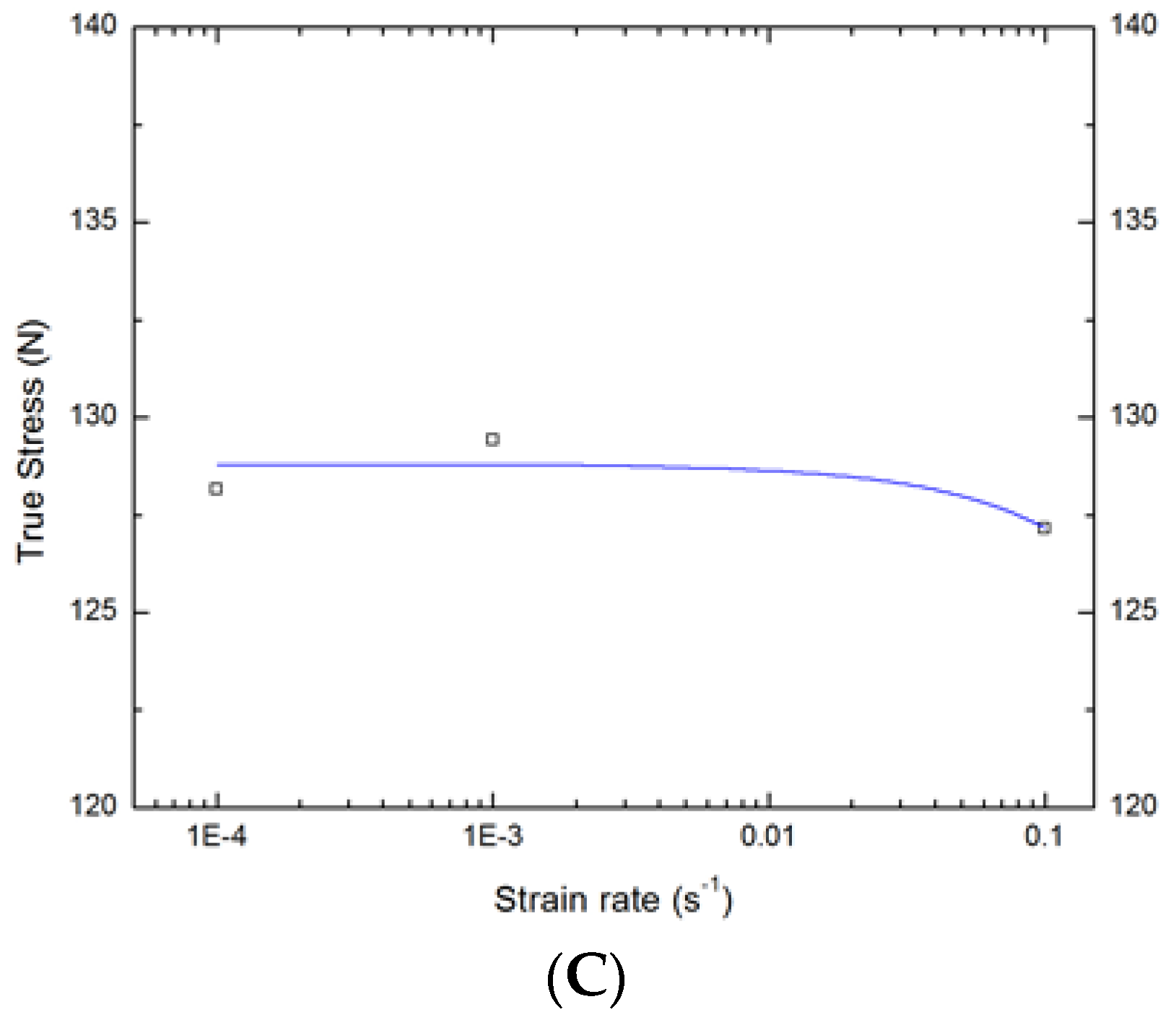
| Strain rate | 0.0001, 0.001, 0.01 | s−1 |
| Parameter | P–B Ratio, x1 (No unit) | Temperature, x2 (K) | Strain Rate, x3 (s−1) | True Stress, y1 (MPa) |
|---|---|---|---|---|
| Mean | 0.35 | 375 | 0.034 | 137.43 |
| Median | 0.35 | 375 | 0.001 | 121.92 |
| Standard deviation | 0.11 | 56.49 | 0.047 | 49.30 |
| Kurtosis | −1.38 | −1.38 | −1.53 | −0.49 |
| Skewness | −1.842 × 10⁻¹⁵ | 0 | 0.730 | 0.75 |
| Minimum | 0.2 | 300 | 10−4 | 69.82 |
| Maximum | 0.5 | 450 | 0.1 | 235 |
| Input Parameter | Percentage Contribution to True Stress (%) |
|---|---|
| P–B ratio | 36 |
| Temperature (K) | 62 |
| Strain rate (s−1) | 2 |
© 2017 by the authors. Licensee MDPI, Basel, Switzerland. This article is an open access article distributed under the terms and conditions of the Creative Commons Attribution (CC BY) license ( http://creativecommons.org/licenses/by/4.0/).
Share and Cite
Vijayaraghavan, V.; Garg, A.; Gao, L.; Vijayaraghavan, R. Finite Element Based Physical Chemical Modeling of Corrosion in Magnesium Alloys. Metals 2017, 7, 83. https://doi.org/10.3390/met7030083
Vijayaraghavan V, Garg A, Gao L, Vijayaraghavan R. Finite Element Based Physical Chemical Modeling of Corrosion in Magnesium Alloys. Metals. 2017; 7(3):83. https://doi.org/10.3390/met7030083
Chicago/Turabian StyleVijayaraghavan, Venkatesh, Akhil Garg, Liang Gao, and Rangarajan Vijayaraghavan. 2017. "Finite Element Based Physical Chemical Modeling of Corrosion in Magnesium Alloys" Metals 7, no. 3: 83. https://doi.org/10.3390/met7030083