
Mechanical Properties Improvement of Laser Tailor Welded Blanks of DP600 Steel by Magnetic Treatment

Abstract
:1. Introduction
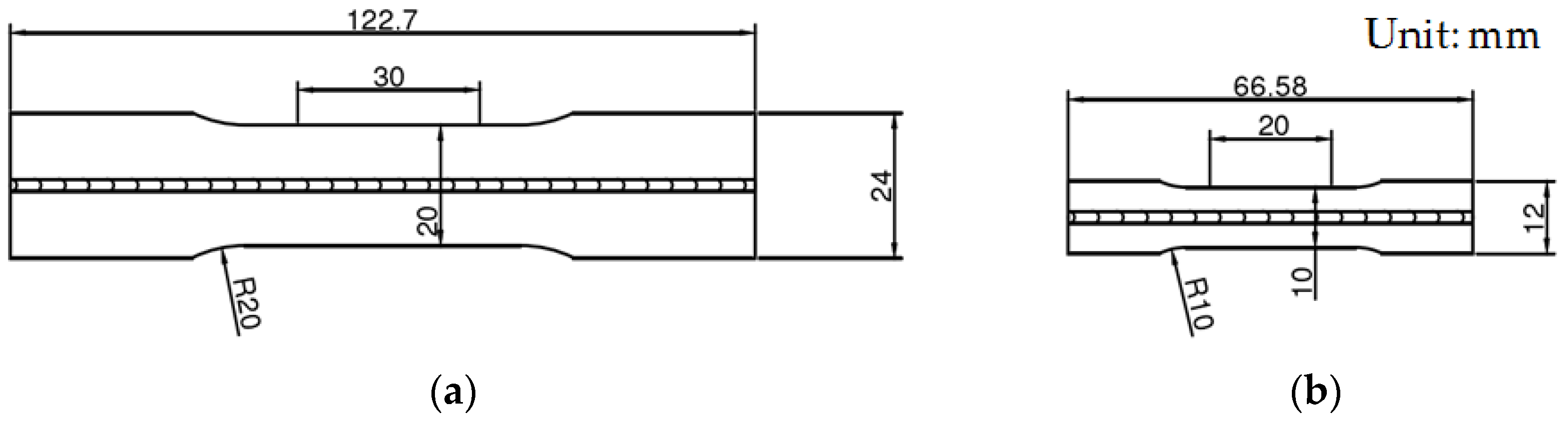
2. Experimental
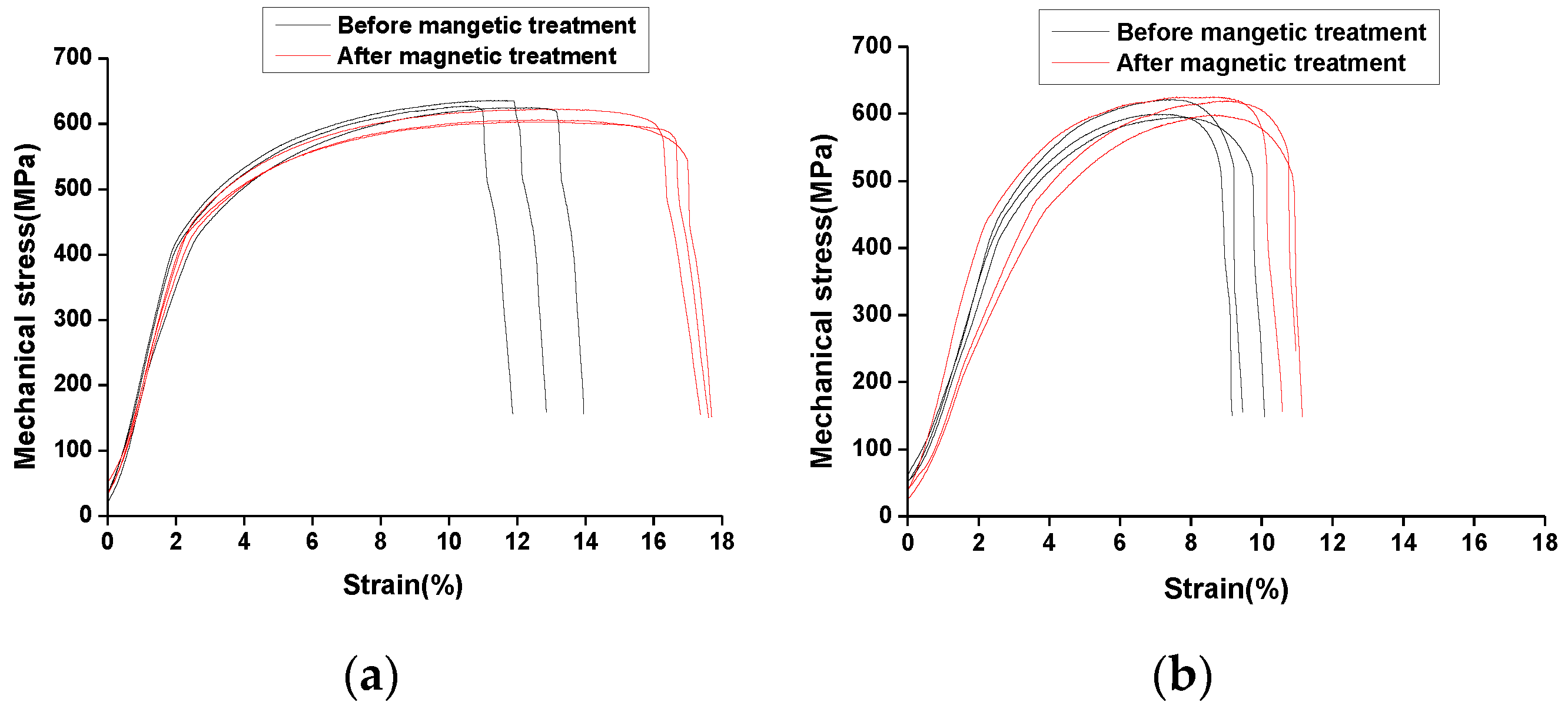
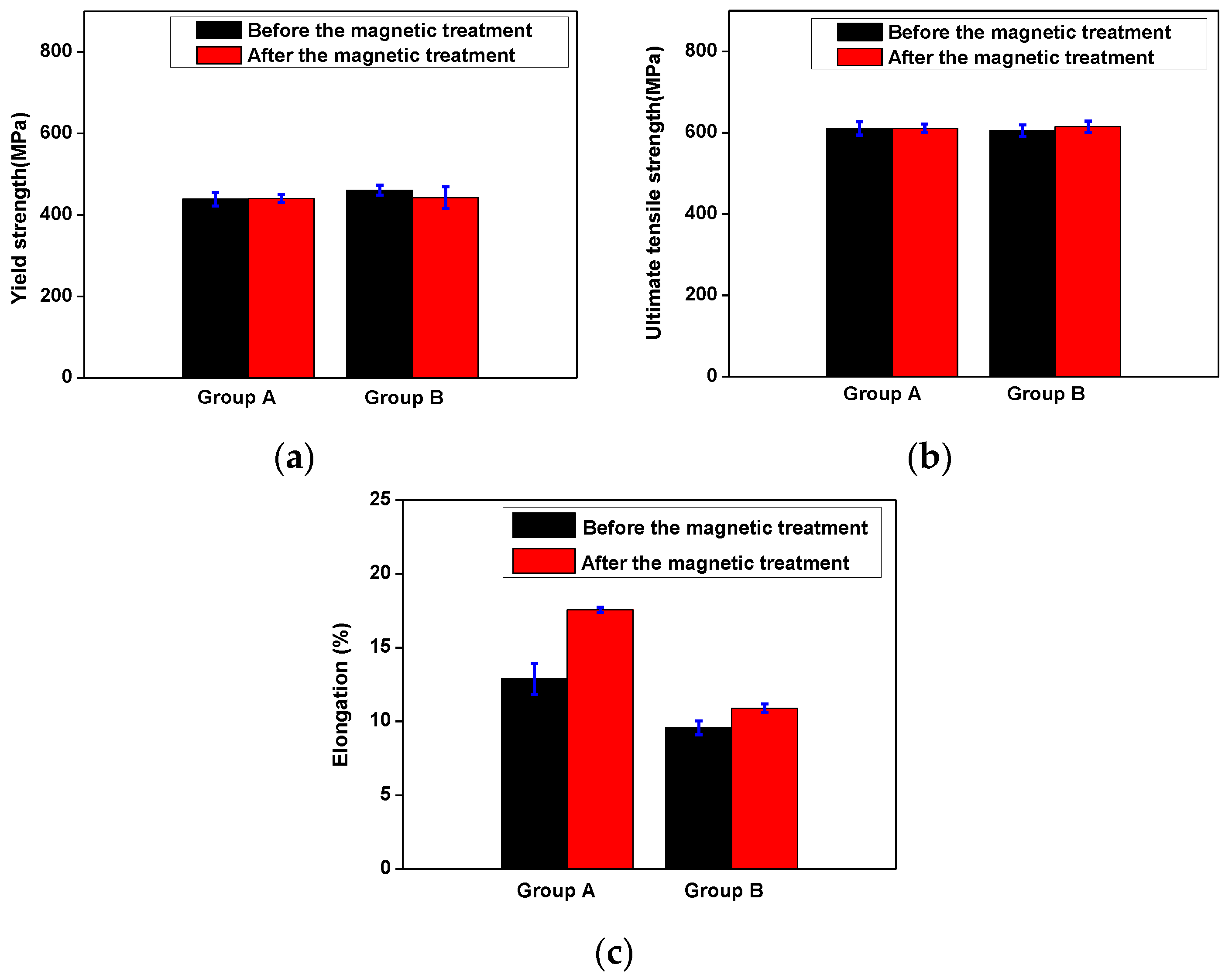
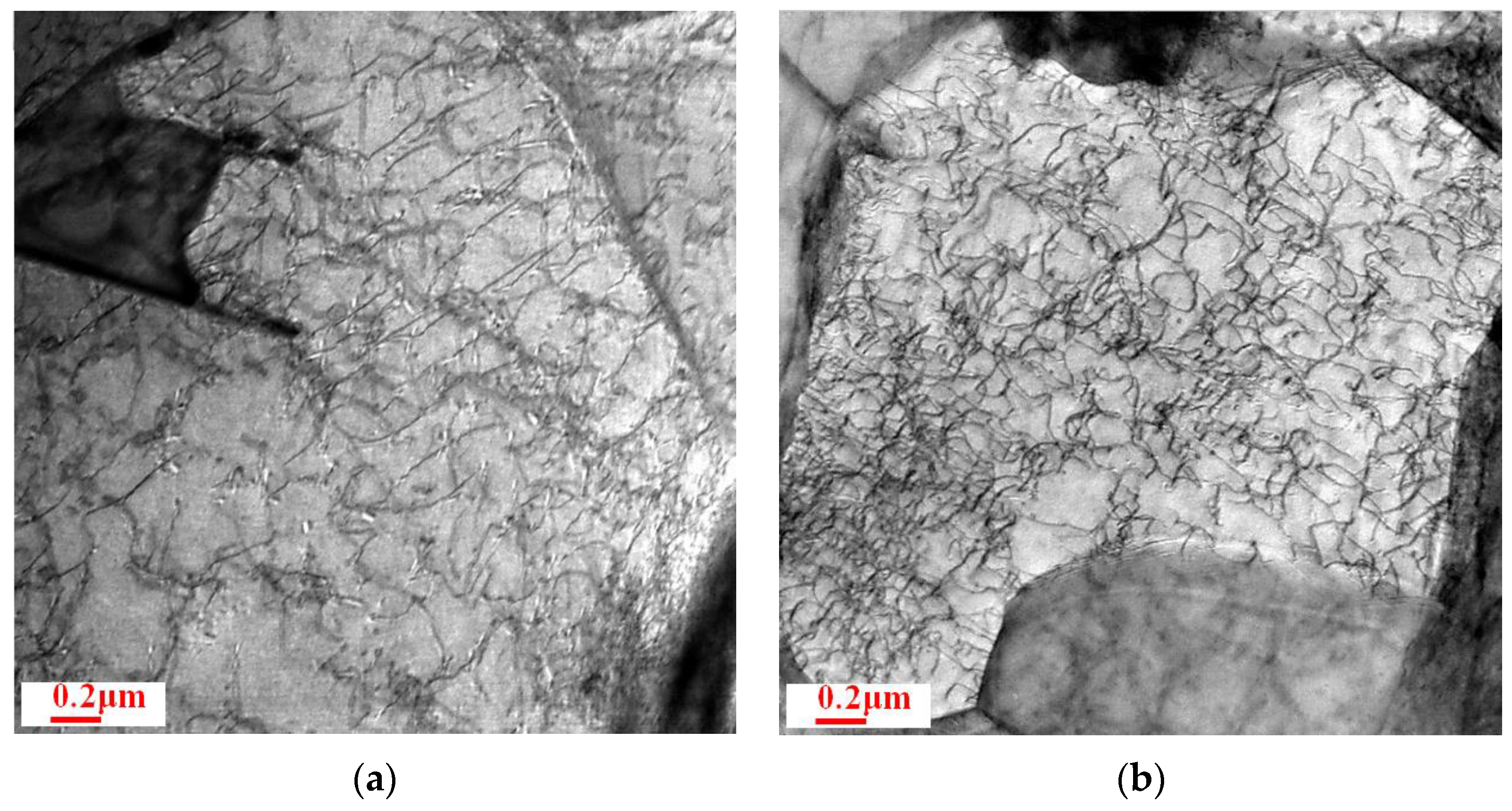
3. Results
4. Discussion
5. Conclusions
Acknowledgments
Author Contributions
Conflicts of Interest
References
- Schrek, A.; Švec, P.; Gajdošová, V. Deformation properties of tailor welded blank made of dual phase steels. Acta Mech. Autom. 2016, 10, 38–42. [Google Scholar] [CrossRef]
- Song, Y.L.; Hua, L.; Meng, F.Z. Inhomogeneous constructive modelling of laser welded bead based on nanoindentation test. Ironmak. Steelmak. 2012, 39, 95–103. [Google Scholar] [CrossRef]
- Song, Y.L.; Hua, L.; Chu, D.N.; Lan, J. Characterization of the inhomogeneous constitutive properties of laser welding beams by the micro-Vickers hardness test and the rule of mixture. Mater. Design 2012, 37, 19–27. [Google Scholar] [CrossRef]
- Padmanabhan, R.; Oliveira, M.C.; Menezes, L.F. Deep drawing of aluminium-steel tailor-welded blanks. Mater. Design. 2008, 29, 154–160. [Google Scholar] [CrossRef]
- Meinders, T.; Berg, A.V.D.; Huétink, J. Deep drawing simulations of tailored blanks and experimental verification. J. Mater. Process. Technol. 2000, 103, 65–73. [Google Scholar] [CrossRef]
- Lee, W.; Chung, K.H.; Kim, D.; Kim, J.; Kim, C.; Okamoto, K.; Wagoner, R.H.; Chung, K. Experimental and numerical study on formability of friction stir welded TWB sheets based on hemispherical dome stretch tests. Int. J. Plast. 2009, 25, 1626–1654. [Google Scholar] [CrossRef]
- Sinha, A.K.; Kim, D.Y.; Ceglarek, D. Correlation analysis of the variation of weld seam and tensile strength in laser welding of galvanized steel. Opt. Lasers Eng. 2013, 51, 1143–1152. [Google Scholar] [CrossRef]
- Song, Y.L.; Hua, L. Influence of inhomogeneous constitutive properties of weld materials on formability of tailor welded blanks. Mater. Sci. Eng. A 2012, 552, 222–229. [Google Scholar] [CrossRef]
- Farabi, N.; Chen, D.L.; Li, J.; Zhou, Y.; Dong, S.J. Microstructure and mechanical properties of laser welded DP600 steel joints. Mater. Sci. Eng. A 2010, 527, 1215–1222. [Google Scholar] [CrossRef]
- Kang, C.Y. Characteristics of Nd:YAG laser welded 600 MPa grade TRIP and DP steels. Mater. Sci. Forum 2007, 539, 3967–3972. [Google Scholar] [CrossRef]
- Lu, A.L.; Tang, F.; Luo, X.; Mei, J.; Fang, F. A new method for residual stress reduction—Pulsed magnetic treatment. China Mech. Eng. 1998, 9, 40–42. [Google Scholar]
- Zhao, W.X.; Yao, H.M.; Liang, Z.Q. Effect of pulsed magnetic field on the micro-hardness of HSS cutting tool materials. Trans. Beijing Inst. Technol. 2014, 34, 661–665. [Google Scholar]
- Celik, A.; Yetim, A.F.; Alsaran, A.; Karakan, M. Effect of magnetic treatment on fatigue life of AISI 4140 steel. Mater. Design 2005, 26, 700–704. [Google Scholar] [CrossRef]
- Klamechi, B.E. Residual stress reduction by pulsed magnetic treatment. J. Mater. Process. Technol. 2003, 141, 385–394. [Google Scholar] [CrossRef]
- Cai, Z.P.; Lin, J.; Zhao, H.Y.; Lu, A.L. Orientation effects in pulsed magnetic field treatment. Mater. Sci. Eng. A 2005, 398, 344–348. [Google Scholar]
- Song, Y.L.; Hua, L. Mechanism of residual stress reduction in low alloy steel by a low frequency alternating magnetic treatment. J. Mater. Process. Technol. 2012, 28, 803–808. [Google Scholar] [CrossRef]
- Standardization Administration of the People’s Republic of China. Metallic Materials-Tensile Testing—Part 1: Method of Test at Room Temperature; GB/228.1-2010; Standardization Administration of the People’s Republic of China: Beijing, China, 2010.
- Geng, G.H. Materials Physics and Properties; Peking University Press: Beijing, China, 2010; pp. 238–267. [Google Scholar]
- Jiang, S.T. Condensed Magnetic Physics; Science Press: Beijing, China, 2003; pp. 378–420. [Google Scholar]
- Song, Y.L. Transition in Structure and Properties of Ferromagnetic Materials Caused by a Low Frequency Alternating Magnetic Field. Master Thesis, Wuhan University of Technology, Wuhan, China, 13 December 2008. [Google Scholar]
- Hu, G.X. Metallography; Shanghai Scientific & Technical Publishers: Shanghai, China, 1980; pp. 63–107. [Google Scholar]
- Wang, Y.N.; Chen, S.J.; Dong, X.C. Dislocation Theory and Its Applications; Metallurgical Industry Press: Beijing, China, 2007; pp. 62–75. [Google Scholar]
- Yang, D.Z. Dislocation and Metal Strengthening Mechanism; Harbin Institute of Technology Press: Harbin, Chain, 1991; pp. 107–134. [Google Scholar]


| Welding Power/(W) | Welding Speed/(m/s) | Defocusing Amount/(m) | Shielding Gas |
|---|---|---|---|
| 1500 | 0.05 | 0 | Argon |
© 2017 by the authors. Licensee MDPI, Basel, Switzerland. This article is an open access article distributed under the terms and conditions of the Creative Commons Attribution (CC BY) license ( http://creativecommons.org/licenses/by/4.0/).
Share and Cite
Song, Y.; Yu, C.; Yu, H.; Zhao, C. Mechanical Properties Improvement of Laser Tailor Welded Blanks of DP600 Steel by Magnetic Treatment. Metals 2017, 7, 85. https://doi.org/10.3390/met7030085
Song Y, Yu C, Yu H, Zhao C. Mechanical Properties Improvement of Laser Tailor Welded Blanks of DP600 Steel by Magnetic Treatment. Metals. 2017; 7(3):85. https://doi.org/10.3390/met7030085
Chicago/Turabian StyleSong, Yanli, Cheng Yu, Hailong Yu, and Chenyu Zhao. 2017. "Mechanical Properties Improvement of Laser Tailor Welded Blanks of DP600 Steel by Magnetic Treatment" Metals 7, no. 3: 85. https://doi.org/10.3390/met7030085