
Microstructural Evolution in AlMgSi Alloys during Solidification under Electromagnetic Stirring


Abstract
:1. Introduction
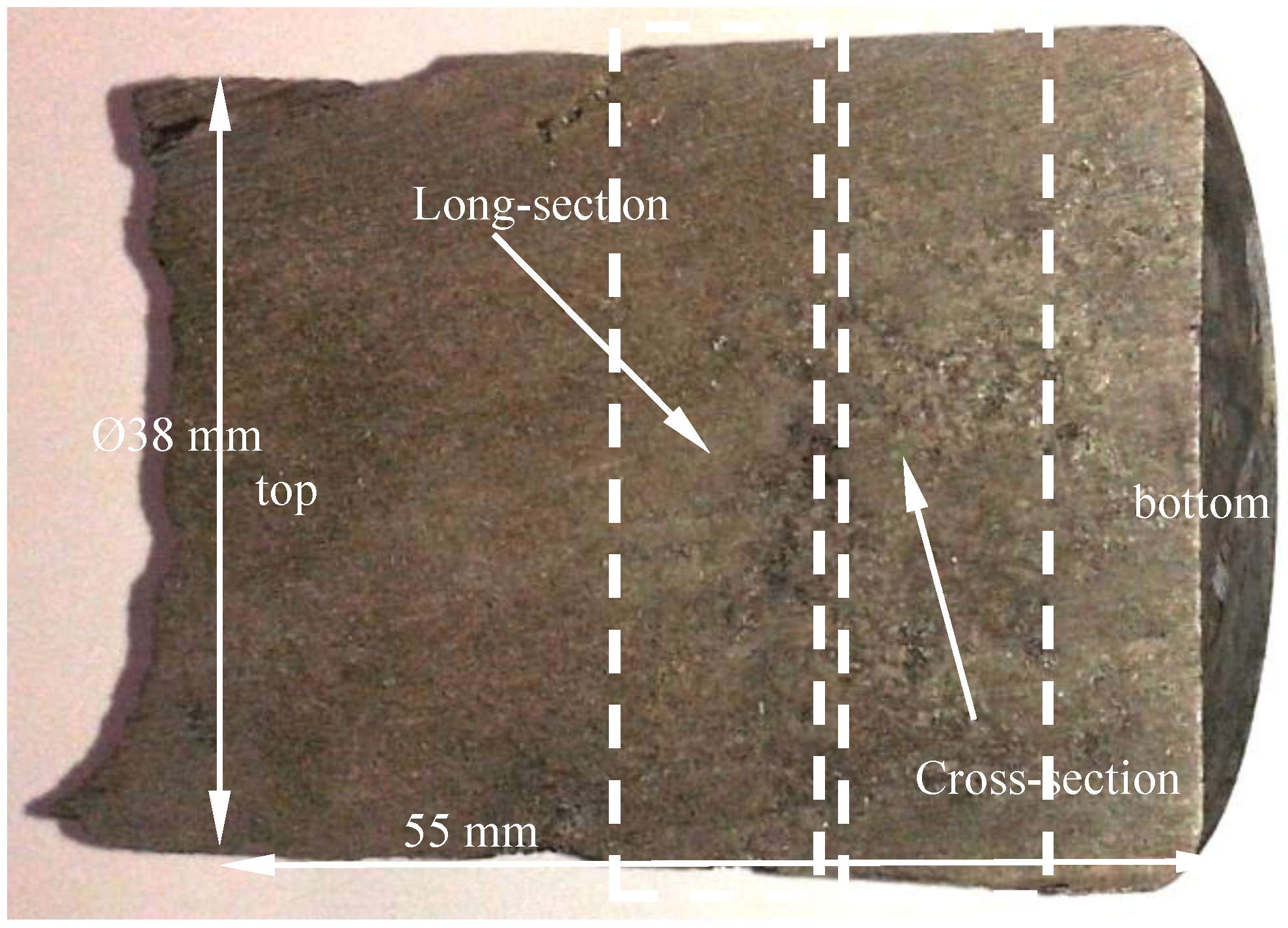
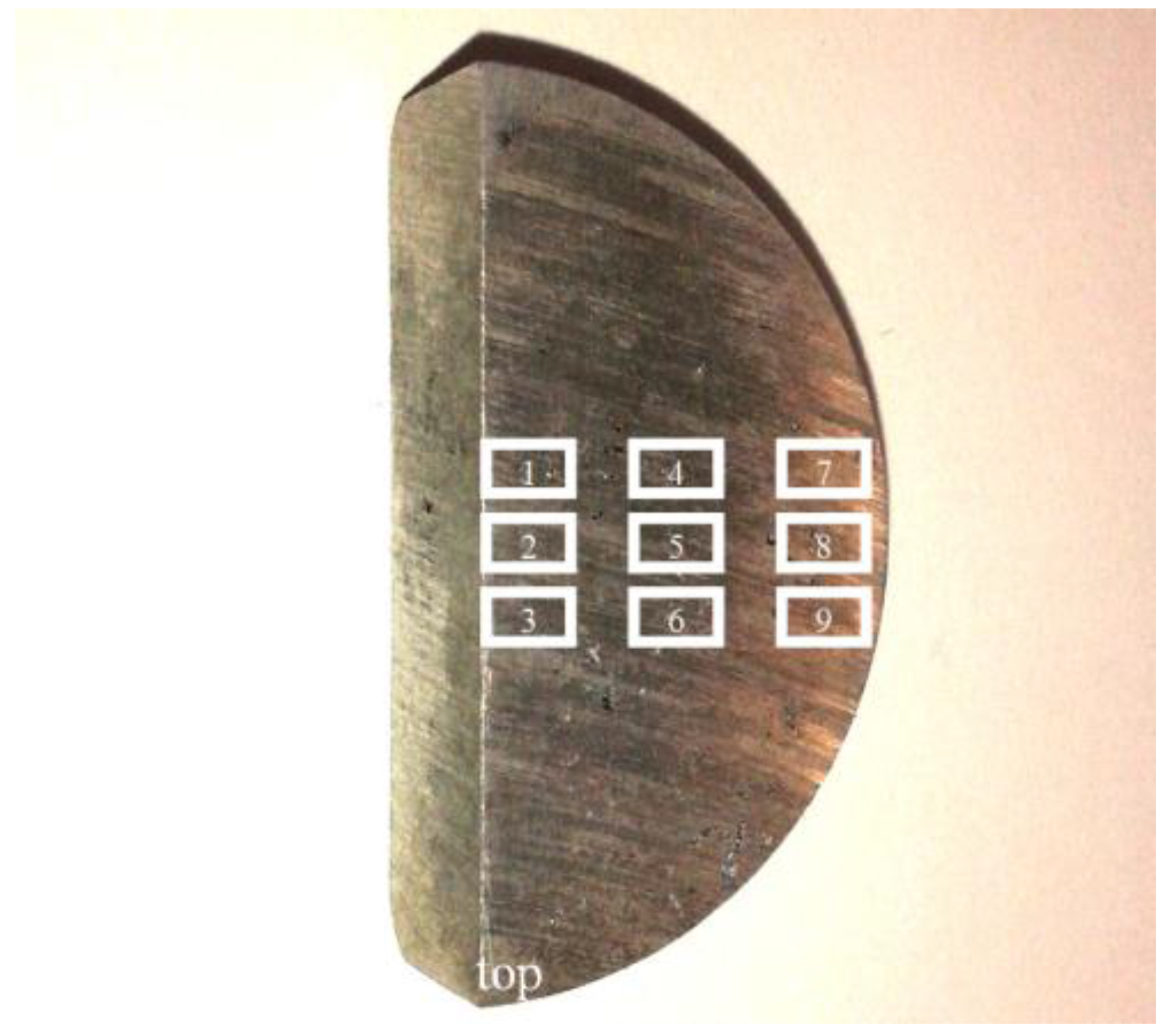
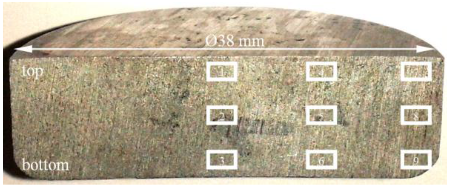
2. Materials and Methods
3. Results
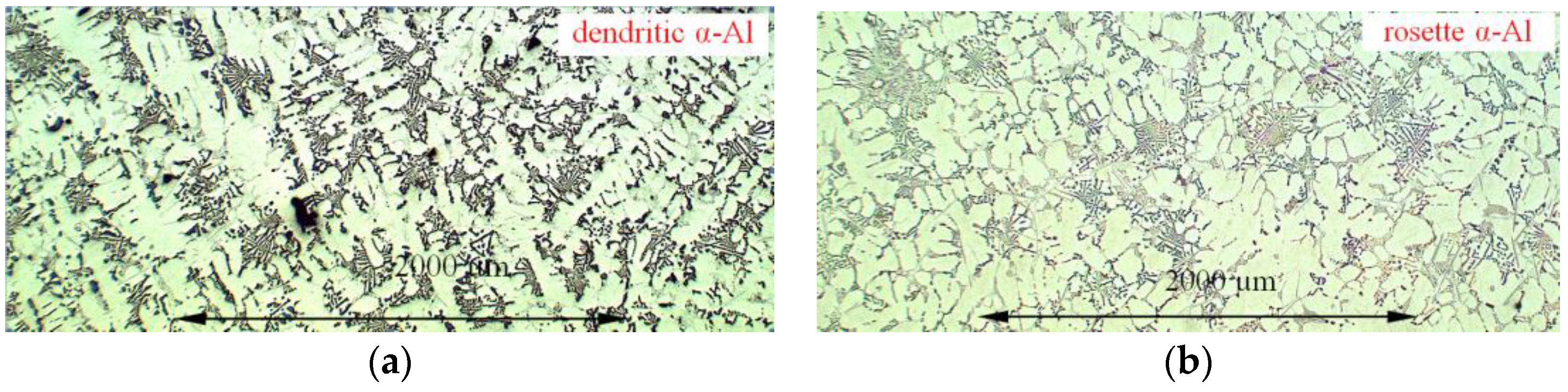
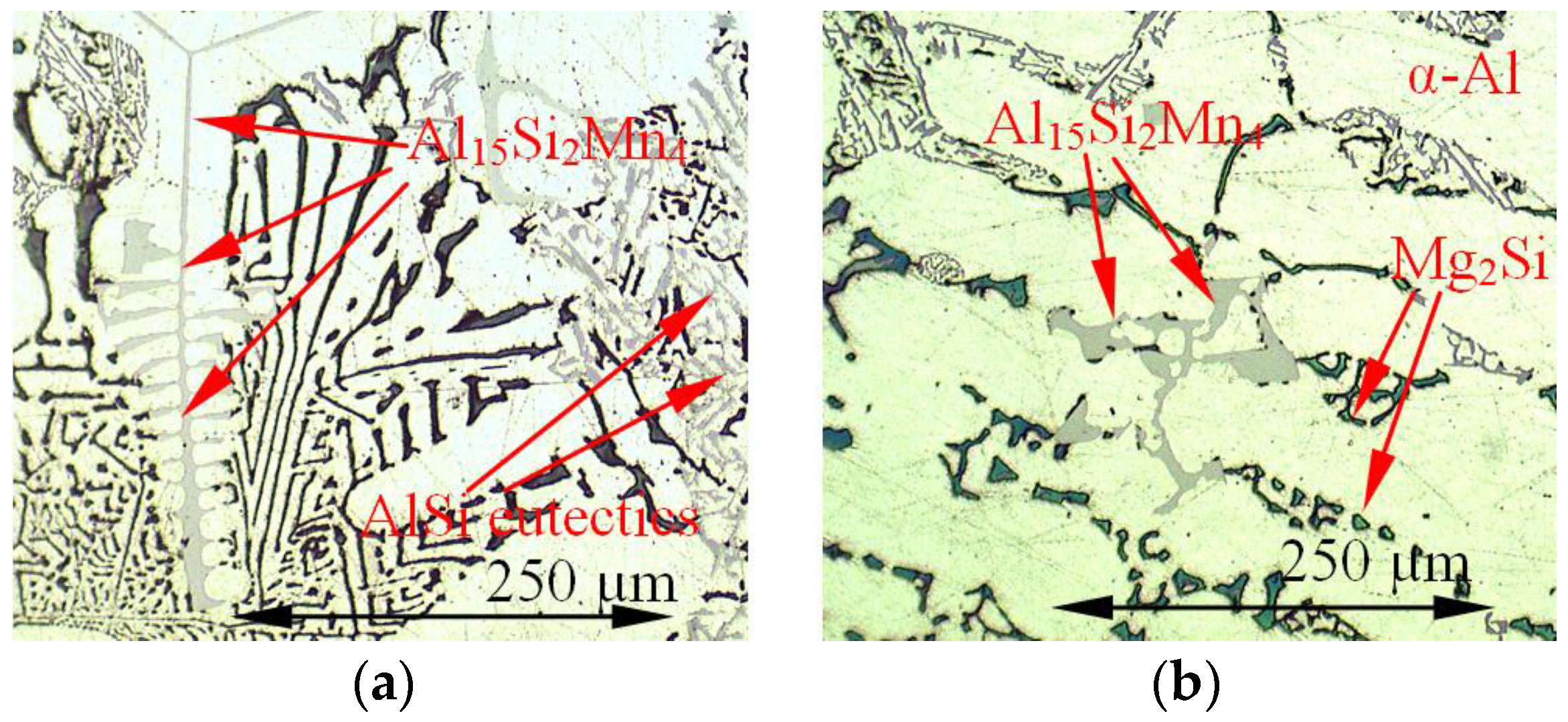
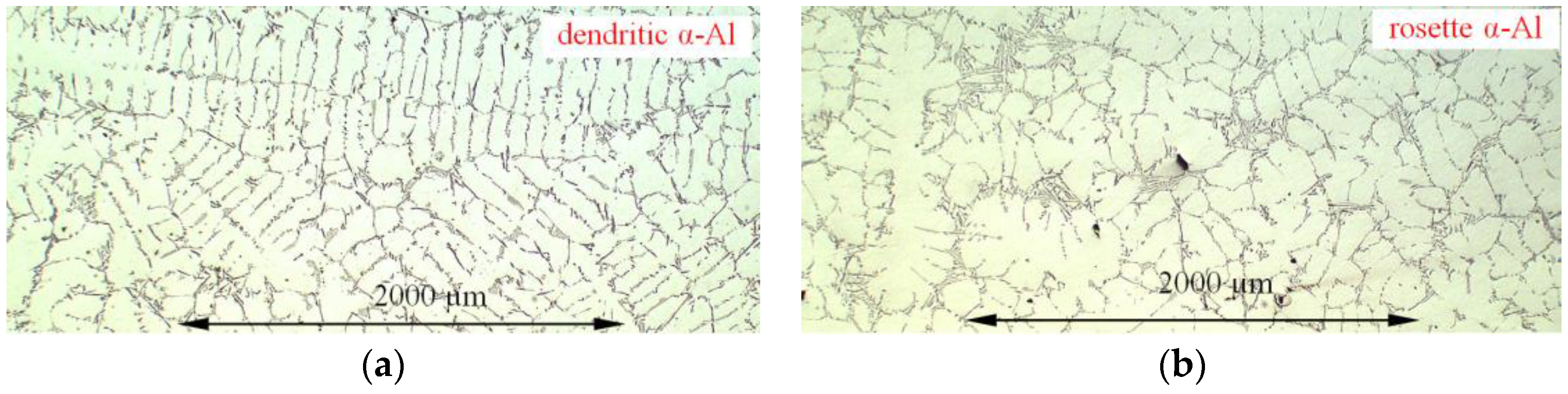
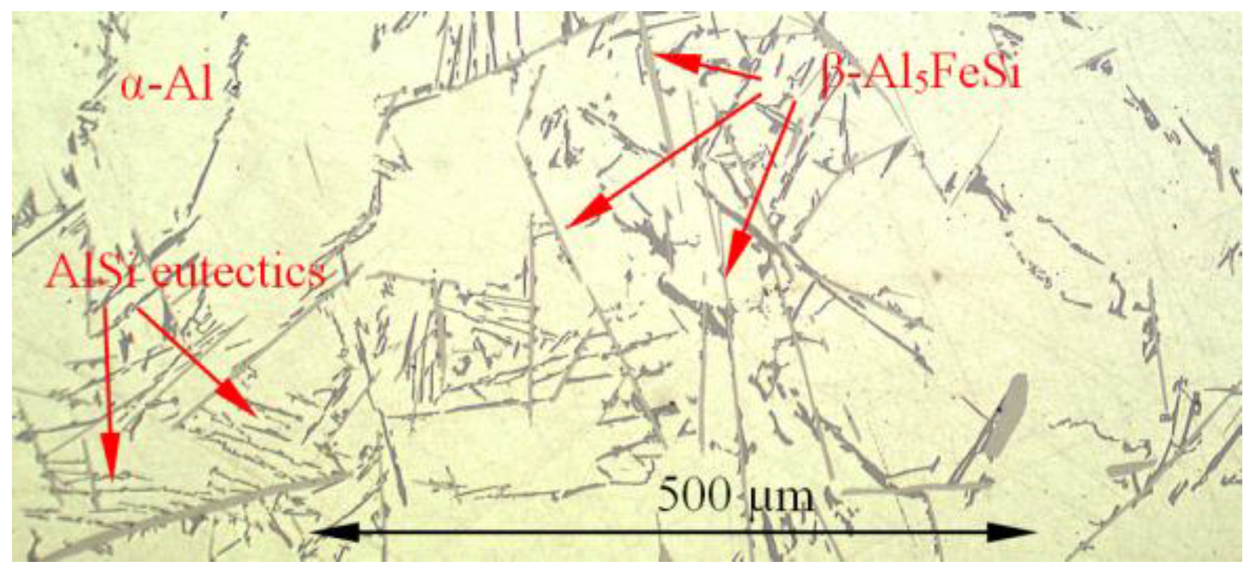
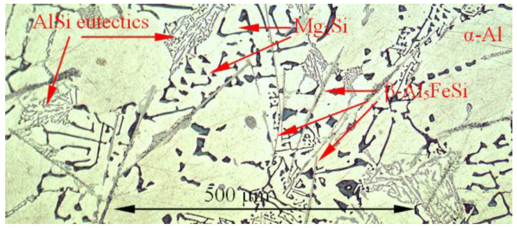
3.1. Microstructure
3.2. Parameters Characterizing Microstructure
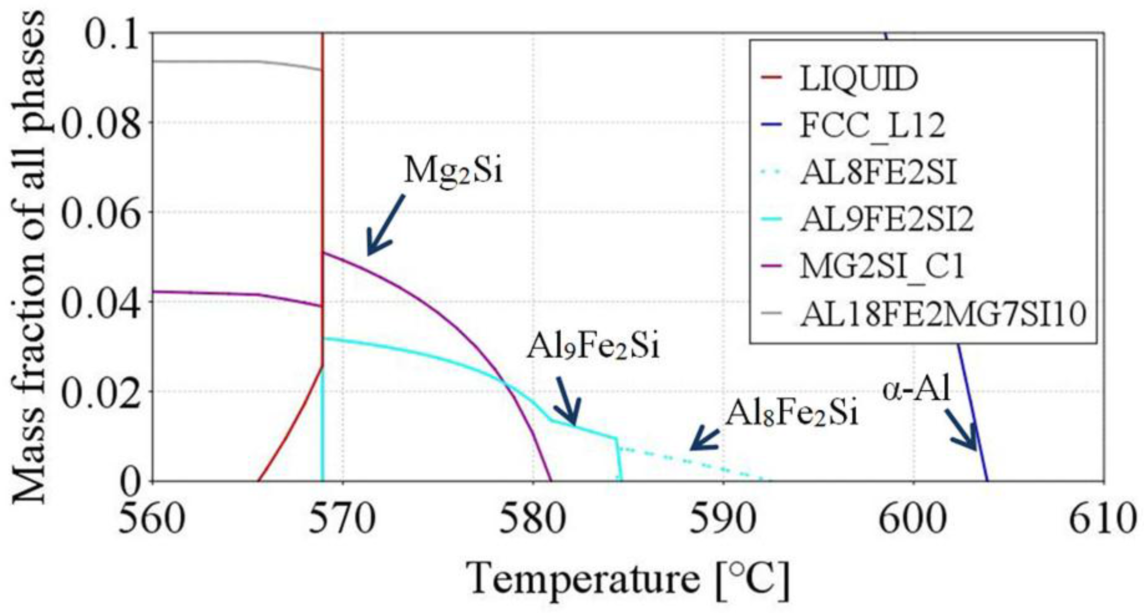
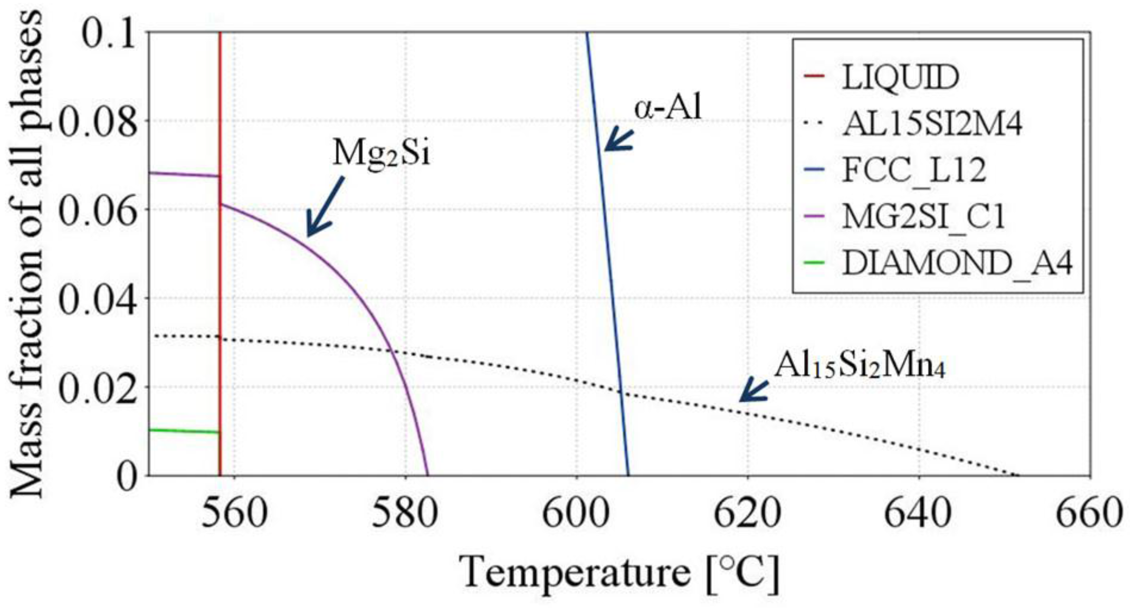
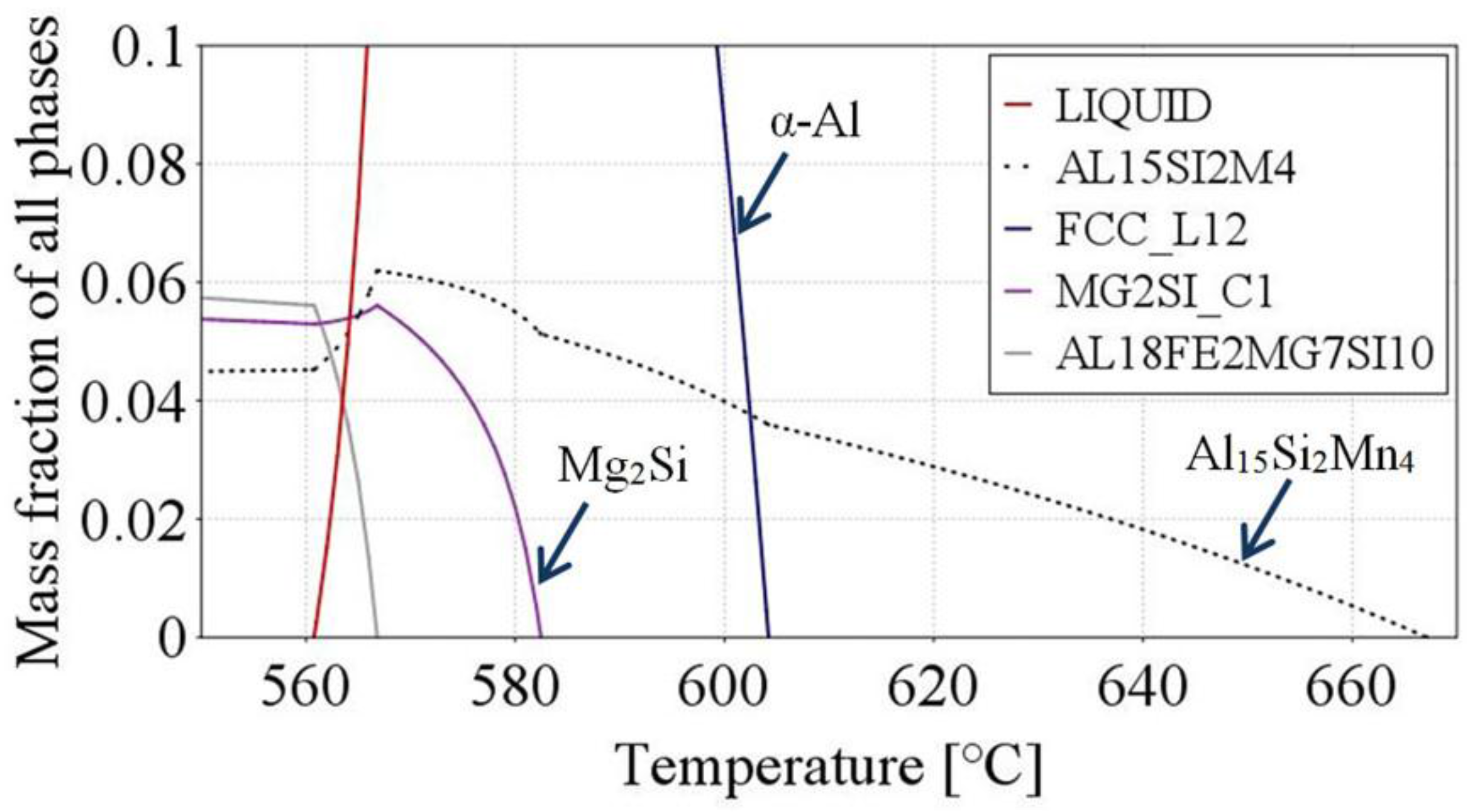
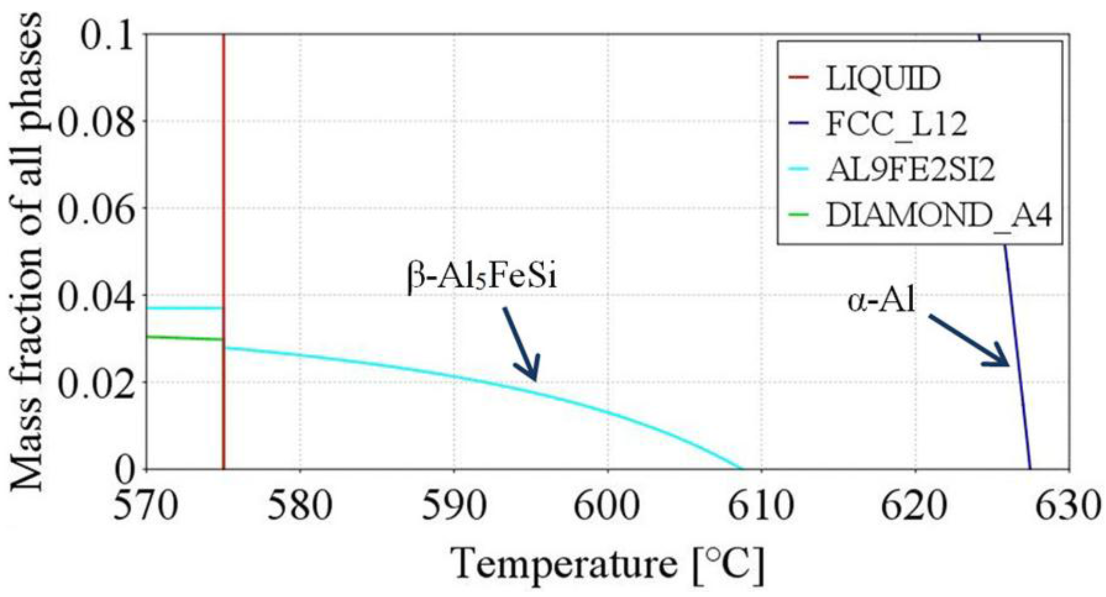
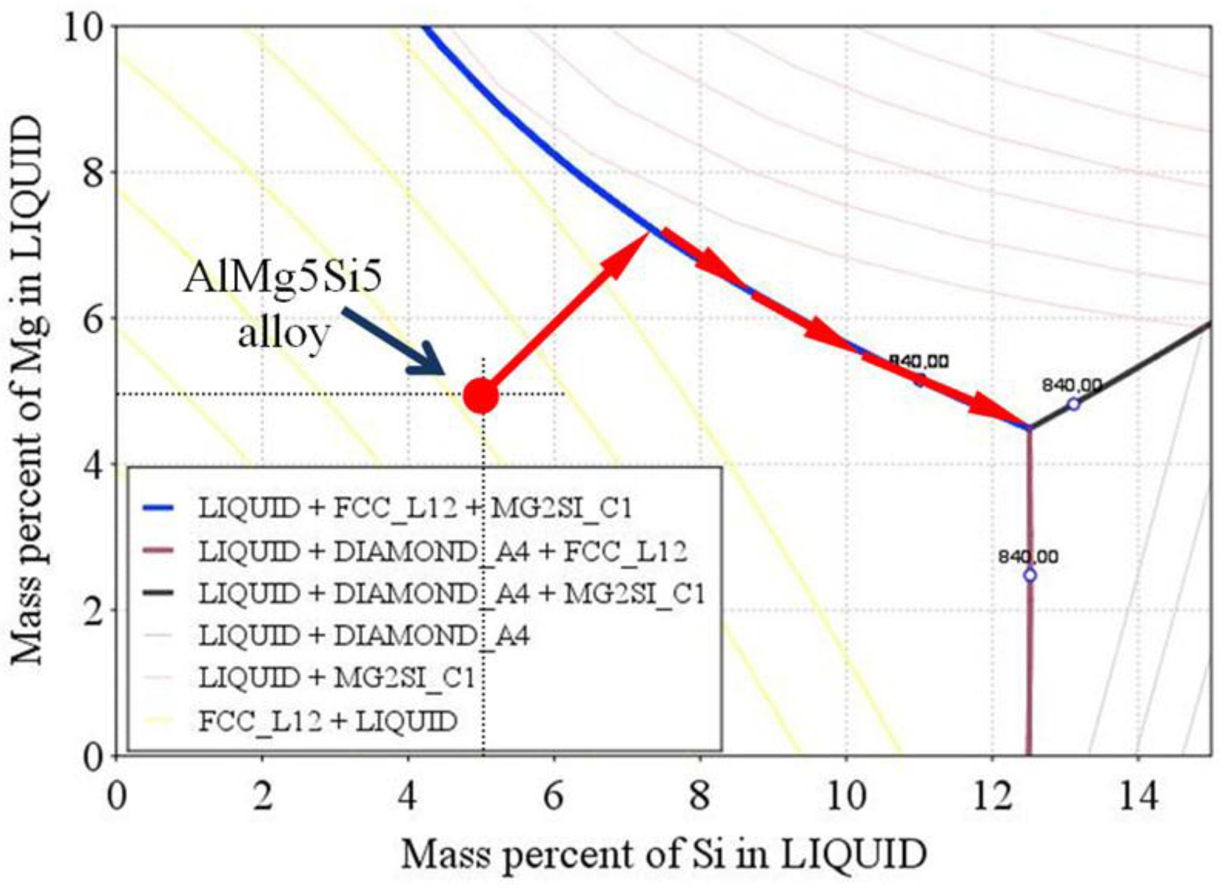
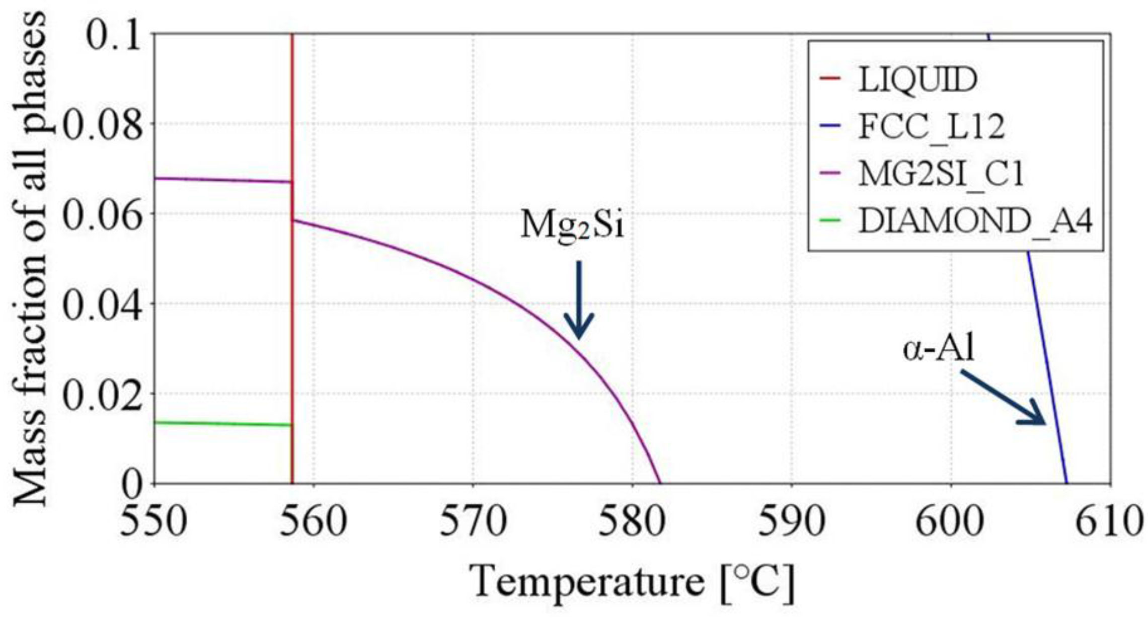
3.3. Precipitation Sequence
4. Discussion
4.1. Rosettes
4.2. Spheroids
4.3. Dendrites
4.4. Eutectics
4.5. Intermetallics
4.6. Solidification by Stirring
5. Conclusions
Acknowledgments
Conflicts of Interest
References
- Flemings, M. Behavior of metal alloys in the semisolid state. Metall. Mater. Trans. B 1991, 22, 269–293. [Google Scholar] [CrossRef]
- Kiuchi, M.; Kopp, R. Mushy/semi-solid metal forming technology–present and future. CIRP Ann. Manuf. Technol. 2002, 51, 653–670. [Google Scholar] [CrossRef]
- Gawroński, J.; Szajnar, J. Properties of Mo59 brass solidification in magnetic field. Solidif. Met. Alloy. 1998, 37, 131–138. [Google Scholar]
- Szajnar, J. The columnar crystals shape and castings structure cast in magnetic field. J. Mater. Process. Technol. 2004, 157–158, 761–764. [Google Scholar] [CrossRef]
- Shabestari, S.G. The effect of iron and manganese on the formation of intermetallic compounds in aluminum-silicon alloys. Mater. Sci. Eng. A 2004, 383, 289–298. [Google Scholar] [CrossRef]
- Gustafsson, G.; Thorvaldsson, T.; Dunlop, G.L. The influence of Fe and Cr on the microstructure of cast Al-Si-Mg alloys. Metall. Mater. Trans. A 1986, 17, 45–52. [Google Scholar] [CrossRef]
- Thermo-Calc 4.1–Software Package from Thermo-Calc Software AB. Stockholm, Sweden. Available online: http://www.thermocalc.se (accessed on 12 March 2015).
- Mikolajczak, P.; Ratke, L. Thermodynamic assessment of mushy zone in directional solidification. Arch. Foundry Eng. 2015, 15, 101–109. [Google Scholar] [CrossRef]
- Mullis, A. Growth induced dendritic bending and rosette formation during solidification in a shearing flow. Acta Mater. 1999, 47, 1783–1789. [Google Scholar] [CrossRef]
- Birol, Y. A357 thixoforming feedstock produced by cooling slope casting. J. Mater. Process. Technol. 2007, 186, 94–101. [Google Scholar] [CrossRef]
- Niroumand, B.; Xia, K. 3D study of the structure of primary crystals in a rheocast Al-Cu alloy. Mater. Sci. Eng. A 2000, 283, 70–75. [Google Scholar] [CrossRef]
- Ji, S.; Fan, Z.; Bevis, M.J. Semi-solid processing of engineering alloys by a twin-screw rheomoulding process. Mater. Sci. Eng. A 2001, 299, 210–217. [Google Scholar] [CrossRef]
- Das, A.; Ji, S.; Fan, Z. Morphological development of solidification structures under forced fluid flow: A Monte Carlo simulation. Acta Mater. 2002, 50, 4571–4585. [Google Scholar] [CrossRef]
- Birol, Y. Evolution of globular microstructures during processing of aluminum slurries. Trans. Nonferrous Met. Soc. China 2013, 23, 1–6. [Google Scholar] [CrossRef]
- Li, T.; Lin, X.; Huang, W. Morphological evolution during solidification under stirring. Acta Mater. 2006, 54, 4815–4824. [Google Scholar] [CrossRef]
- Martinez, R.A.; Flemings, M.C. Evolution of particle morphology in semisolid processing. Metall. Mater. Trans. A 2005, 36, 2205–2210. [Google Scholar] [CrossRef]
- Kurz, W.; Fisher, D. Fundamentals of Solidification; Trans Tech Public.: Zurich, Switzerland, 1992; pp. 85–90. [Google Scholar]
- Dantzig, J.A.; Rappaz, M. Solidification; EPFL Press: Lausanne, Switzerland, 2009. [Google Scholar]
- Stefanescu, D. Science and Engineering of Casting and Solidification; Springer Science+Media Business: New York, NY, USA, 2009. [Google Scholar] [CrossRef]
- Mendoza, R.; Alkemper, J.; Voorhees, P. The morphological evolution of dendritic microstructures during coarsening. Metall. Mater. Trans. A 2003, 34, 481–489. [Google Scholar] [CrossRef]
- Hunt, J.D. Pattern formation in solidification. Sci. Technol. Adv. Mater. 2001, 2, 147–155. [Google Scholar] [CrossRef]
- Hunt, J.D.; Lu, S.Z. Numerical modeling of cellular/dendritic array growth: Spacing and structure predictions. Metall. Mater. Trans. A 1996, 27, 611–623. [Google Scholar] [CrossRef]
- Kattamis, T.Z.; Flemings, M.C. Dendrite morphology, Microsegregation and Homogenization of low alloy steel. Trans. Met. Soc. AIME 1965, 233, 992–999. [Google Scholar]
- Rappaz, M.; Boettinger, W. On dendritic solidification of multicomponent alloys with unequal liquid diffusion coefficients. Acta Mater. 1999, 47, 3205–3219. [Google Scholar] [CrossRef]
- Steinbach, S.; Ratke, L. The influence of fluid flow on the microstructure of directionally solidified AlSi-base alloys. Metall. Mater. Trans. A 2007, 38, 1388–1394. [Google Scholar] [CrossRef]
- Voorhees, P.W.; Glicksman, M.E. Ostwald ripening during liquid phase sintering–Effect of volume fraction on coarsening kinetics. Metall. Mater. Trans. A 1984, 15, 1081–1089. [Google Scholar] [CrossRef]
- Mortensen, A. On the rate of dendrite arm coarsening. Metall. Mater. Trans. A 1991, 22, 569–574. [Google Scholar] [CrossRef]
- Bouchard, D.; Kirkaldy, J.S. Prediction of dendrite arm spacing in unsteady- and steady-state heat flow. Metall. Mater. Trans. B 1997, 28, 651–663. [Google Scholar] [CrossRef]
- Mullis, A.M. The effects of fluid flow on the secondary arm coarsening during dendritic solidification. J. Mater. Sci. 2003, 38, 2517–2523. [Google Scholar] [CrossRef]
- Diepers, H.J.; Beckerman, C.; Steinbach, I. Simulation of convection and ripening in a binary alloy mush using the phase field method. Acta Mater. 1999, 47, 3663–3678. [Google Scholar] [CrossRef]
- Ratke, L.; Thieringer, W.K. The influence of particle motion on Ostwald ripening in liquids. Acta Mater. 1985, 33, 1793–1802. [Google Scholar] [CrossRef]
- Marsh, S.P.; Glicksman, M.E. Overview of geometric effects on coarsening of mushy zones. Metall. Mater. Trans. A 1996, 27, 557–567. [Google Scholar] [CrossRef]
- Kasperovich, G.; Genau, A.; Ratke, L. Mushy zone coarsening in an AlCu30 alloy accelerated by a rotating magnetic field. Metall. Mater. Trans. A 2011, 42, 1657–1666. [Google Scholar] [CrossRef]
- Jackson, K.A.; Hunt, J.D. Lamellar and rod eutectic growth. Trans. AIME 1966, 236, 1129–1142. [Google Scholar]
- Mikolajczak, P.; Ratke, L. Intermetallic phases and microstructure in AlSi alloys influenced by fluid flow. In The Minerals, Metals & Society TMS; John Wiley & Sons. Inc.: San Francisco, CA, USA, 2011. [Google Scholar] [CrossRef]
- Sous, S. Instationäre Erstarrung Eutektischer Al-Si Legierungen. Ph.D. Thesis, RWTH, Aachen, Germany, 2000. [Google Scholar]
- Nafisi, S.; Emad, D.; Shehata, T.; Ghomashchi, R. Effects of electromagnetic stirring and superheat on the microstructural characteristics of Al-Si-Fe alloy. Mater. Sci. Eng. A 2006, A432, 71–83. [Google Scholar] [CrossRef]
- Fang, X.; Shao, G.; Liu, Y.Q.; Fan, Z. Effects of intensive forced melt convection on the mechanical properties of Fe containing Al-Si based alloys. Mater. Sci. Eng. A 2007, 445–446, 65–72. [Google Scholar] [CrossRef]
- Steinbach, E.N.; Witusiewicz, V.; Sturz, L.; Ratke, L. Fluid flow effects on intermetallic phases in Al-cast alloys. Trans. Indian Inst. Met. 2007, 60, 137–141. [Google Scholar] [CrossRef]
- Mikolajczak, P.; Ratke, L. Effect of stirring induced by rotating magnetic field on β-Al5FeSi intermetallic phases during directional solidification in AlSi alloys. Int. J. Cast Met. Res. 2013, 26, 339–353. [Google Scholar] [CrossRef]


| Aluminium Alloys | RMF (mT) {Solid. Time (s)} | Microstructure Parameters | |||||||
|---|---|---|---|---|---|---|---|---|---|
| Dendrites | Fe-phases (β-Al5FeSi) | Mn-phases | AlSi eutectics | Mg2Si | |||||
| λSDAS (µm) | Sv (µm−1) | Lβ (µm) | nβ (mm−2) | LMn (µm) | nMn (mm−2) | λEut (µm) | λMg2Si (µm) | ||
| AlSi5Fe1 | 0{468} | 87 [6.7] (60/652) | 0.023 [0.002] | 71 [4.1] (1571) | 109 | - | - | 8.5 [0.3] | - |
| 11{393} | 77 [5.7] (68/631) (−12%) | 0.019 [0.001] (−17%) | 57 [4.1] (2306) (−20%) | 160 (47%) | - | - | 9.5 [0.3] | - | |
| AlMg5Si5 | 0{584} | 67 [5.1] (134/1135) | 0.036 [0.004] | - | - | - | - | 9.8 [0.3] | 9.7 [0.5] (5–20) |
| 11{495} | 68 [4.0] (109/880) | 0.024 [0.002] (−33%) | - | - | - | - | 8.8 [0.3] | 10.1 [0.5] (4.8–18.6) | |
| AlMg5Si5Fe1 | 0{537} | 60 [4.5] (153/1399) | 0.034 [0.003] | 79 [4.9] (1043) | 72 | - | - | 11.7 [0.6] | 11.7 [0.6] (5.3–19.3) |
| 11{477} | 62 [4.0] (150/864) | 0.026 [0.002] (−24%) | 75 [5.4] (1178) (−5%) | 82 (14%) | - | - | 6.8 [0.2] | 12.7 [0.4] (6.3–18.2) | |
| AlMg5Si5Mn1 | 0{686} | 65 [5.0] (136/1054) | 0.036 [0.003] | - | - | 299 [13.3] | 20 | 7.5 [0.3] | 11.6 [0.7] (5.6–19.0) |
| 11{638} | 65 [4.9] (117/599) | 0.028 [0.002] (−24%) | - | - | 273 [15.1] (−9%) | 27 | 8.7 [0.2] | 12.0 [0.7] (4.3–20.6) | |
| AlMg5Si5Fe1Mn1 | 0{723} | 62 [4.5] (109/678) | 0.035 [0.002] | 44 [2.2] (128) | 9 | - | - | 8.1 [0.3] | 11.3 [0.7] (5.1–18.4) |
| 11{627} | 62 [5.2] (116/382) | 0.028 [0.002] (−20%) | 43 [2.4] (229) (−2%) | 16 (77%) | - | - | 9.1 [0.2] | 12.1 [0.7] (5.8–19.1) | |
© 2017 by the author. Licensee MDPI, Basel, Switzerland. This article is an open access article distributed under the terms and conditions of the Creative Commons Attribution (CC BY) license ( http://creativecommons.org/licenses/by/4.0/).
Share and Cite
Mikolajczak, P. Microstructural Evolution in AlMgSi Alloys during Solidification under Electromagnetic Stirring. Metals 2017, 7, 89. https://doi.org/10.3390/met7030089
Mikolajczak P. Microstructural Evolution in AlMgSi Alloys during Solidification under Electromagnetic Stirring. Metals. 2017; 7(3):89. https://doi.org/10.3390/met7030089
Chicago/Turabian StyleMikolajczak, Piotr. 2017. "Microstructural Evolution in AlMgSi Alloys during Solidification under Electromagnetic Stirring" Metals 7, no. 3: 89. https://doi.org/10.3390/met7030089