Article

Comparison of Single Ti6Al4V Struts Made Using Selective Laser Melting and Electron Beam Melting Subject to Part Orientation

1
Faculty of Engineering, University of Applied Science, Technology, Business and Design, Philipp-Müller-Str. 14, 23966 Wismar, Germany
2
Biomechanics and Implant Technology Research Laboratory, Department of Orthopedics, University Medicine Rostock, Doberaner Strasse 142, 18057 Rostock, Germany
3
Fluidic Technology and Microfluidics, Faculty of Mechanical Engineering and Marine Technology, University of Rostock, 18059 Rostock, Germany
4
Institute for Polymer Technologies e.V., Alter Holzhafen 19, 23966 Wismar, Germany
*
Author to whom correspondence should be addressed.
Metals 2017, 7(3), 91; https://doi.org/10.3390/met7030091
Submission received: 1 December 2016 / Revised: 8 March 2017 / Accepted: 9 March 2017 / Published: 11 March 2017
(This article belongs to the Special Issue 3D Printing of Metals)

Abstract

:
The use of additive manufacturing technologies to produce lightweight or functional structures is widespread. Especially Ti6Al4V plays an important role in this development field and parts are manufactured and analyzed with the aim to characterize the mechanical properties of open-porous structures and to generate scaffolds with properties specific to their intended application. An SLM and an EBM process were used respectively to fabricate the Ti6Al4V single struts. For mechanical characterization, uniaxial compression tests and hardness measurements were conducted. Furthermore, the struts were manufactured in different orientations for the determination of the mechanical properties. Roughness measurements and a microscopic characterization of the struts were also carried out. Some parts were characterized following heat treatment (hot isostatic pressing). A functional correlation was found between the compressive strength and the slenderness ratio (λ) as well as the equivalent diameter (d) and the height (L) of EBM and SLM parts. Hardness investigations revealed considerable differences related to the microstructure. An influence of heat treatment as well as of orientation could be determined. In this work, we demonstrate the influence of the fabrication quality of single struts, the roughness and the microstructure on mechanical properties as a function of orientation.

Graphical Abstract

1. Introduction

The development of structures using modern AM (additive manufacturing) technologies is a steadily growing research field in recent years. Here, complex and weight-saving structures arouse special interest. One important goal is frequently the targeted dimensioning of mechanical properties.
The progress in additive manufacturing technology makes this more tangible. An essential prerequisite is to develop a better understanding of the technological contexts of additive manufacturing technologies.
Of strong interest is the relationship between the materials used, the process parameters, especially in the application field of open-porous load-bearing lattice structures, and their effects on mechanical properties. Other methods, in particular, electron beam melting (EBM), are widely used in addition to selective laser melting (SLM). Their suitability for the manufacture of components for applications with a bio-medical background has in many cases been confirmed [1,2,3].
Besides pure titanium and titanium alloys [4,5], pure tantalum [6,7] is also used as a material for the production of sufficiently resilient mechanical load-bearing elements.
Additive manufacturing and the three-dimensional design of components or structures using Ti6Al4V powder offer a wide range of unprecedented applications in medical technology thanks to their multifarious properties (biomedical compatibility, corrosion resistance, mechanical properties). The mechanical properties essentially define the suitability and successful application of mechanically optimized structures, such as bone substitutes, in biomedical fields [8,9,10].
The geometrical shape as well as the properties of the structures produced can be influenced directly through the manufacturing parameters [11,12,13] and through heat treatment [14,15].
In the development of open porous load-bearing structures, the orientation of the load-bearing rods and the load angle [16,17,18,19] as well as the relationship between elastic modulus and porosity play an important role [20,21].
Open porous load-bearing lattice structures consist of a regularly or irregularly composed form of geometrically describable individual elements. Here, simple lattice structures [22] play just as great a role as geometrically complicated forms (gyroid) [23]. Efforts to characterize the widespread lattice structures [24] range from studies of the mechanical properties to macroscopic and microscopic investigations.
The large number of research projects shows the high relevance of grid structures in engineering applications. The intention here is to create specific qualities by producing structures with a high degree of freedom, as for example in medical applications. The mechanical qualities again are the central consideration. The characterization of the relevant properties is carried out primarily on complete lattice structures [25], standard specimens [26,27] or on application models with a biomedical background [28,29,30].
The efforts of many research groups focus on the estimation of the mechanical properties using numeric methods. Labes et al. [31] developed a method for studying the structural response and failure process of open stainless steel 316 L lattice structures manufactured using SLM. They predicted the elastic modulus of several lattice structures with various strut ratios. To predict the quasi-static response and failure of different core lattice structures he used linear static and non-linear elasto-plastic analysis. Ahmadi et al. [32] present a new analytical solution and closed-form relationship for predicting mechanical properties, such as the elastic modulus and critical buckling load. To estimate the mechanical properties of the diamond lattice, they used an analytical solution based on the Euler–Bernoulli theory and an analytical solution based on the Timoshenko beam theory.
In addition to the estimation of the mechanical properties, work is focused on obtaining results and comparing them to predictions. Ushijima et al. [33] compared analytical and FE predictions of lattice structures with experimental results. To predict the initial stiffness and plastic collapse strength of lattice structures, he used beam elements as well as a BCC (body-centered cubic) unit cell topology. Suard et al. [34] presented a standardized method for predicting the mechanical response of lattice structures manufactured using EBM. Two equivalent diameters were defined to simulate the properties of the lattice structure while taking the manufacturing constraints into account. Deshpande et al. [35] discussed the mechanism of bending and stretching dominated architectures from cellular solids using experimental and theoretical techniques. Mazur et al. [36] theoretically predicted the deformation behavior of lattice structures in different cell topologies, cell sizes and cell numbers, and experimentally validated the results.
Lastly, the mechanical properties are experimentally determined, evaluated and compared between the test partners and relationships. McKown et al. [37] tested a range of metallic lattice structures to investigate their collapse behavior, failure mechanisms and strain-rate sensitivity.
In the present work are described the properties of the individual elements used for the formation of the lattice structures. The identification of properties was therefore carried out on elements that correspond to real geometric conditions as for the lattice structures. It is of major interest to determine the properties of individual bars integrated into specialized applications. This is particularly interesting for applications where the rods within a component show different orientations to the load (see Figure 1) and the structural parameters cannot be compared with typical scaffolds (as shown in the literature). Therefore, the strut elements are considered in this work. The strut elements form the basis for load-bearing porous structures. Variations in the geometry of the test specimen as well as in the manufacturing process can be excluded here. In addition to characterizing production quality and surface quality of the individual struts, selected mechanical properties were determined. The samples were manufactured using additive technologies with variations in dimension (variations in the height/diameter ratio) and also installation space orientation. Selective laser melting and electron beam melting were the two manufacturing processes used to provide the possibility to compare both methods. Furthermore, the directional dependencies can be represented with reference to the properties.
Previous works comparing the two manufacturing methods mentioned above refer to test specimens with geometric dimensions that greatly differ from those of the individual elements of the grid structures [38]. In addition, the focus is always placed on determining such properties that would presuppose tensile loading. Simonelli et al. [39] studied the tensile properties of SLM Ti6Al4V specimens in three directions consisting of 2000, 200 and 60 layers. Qiu et al. [40] examined the tensile properties of Ti6Al4V specimens in dimensions that are not relevant in small lattice structures. A load situation that often is of interest in biomedical applications is the pressure load (for example, in orthopedic cases). The present work therefore studies the mechanical properties of the manufactured test specimens under an applied pressure load.
The aim was to characterize the individual struts macroscopically, microscopically and mechanically. The results obtained shall be used to gain a better understanding of the behavior of the individual elements. The results can be transferred into medical applications. These primarily include the structural areas for implants constructed from grid elements.

2. Materials and Methods

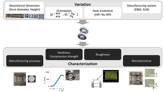
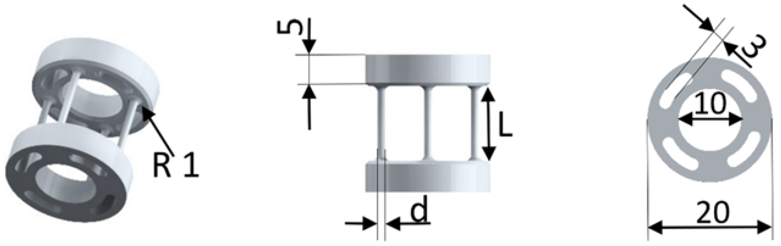
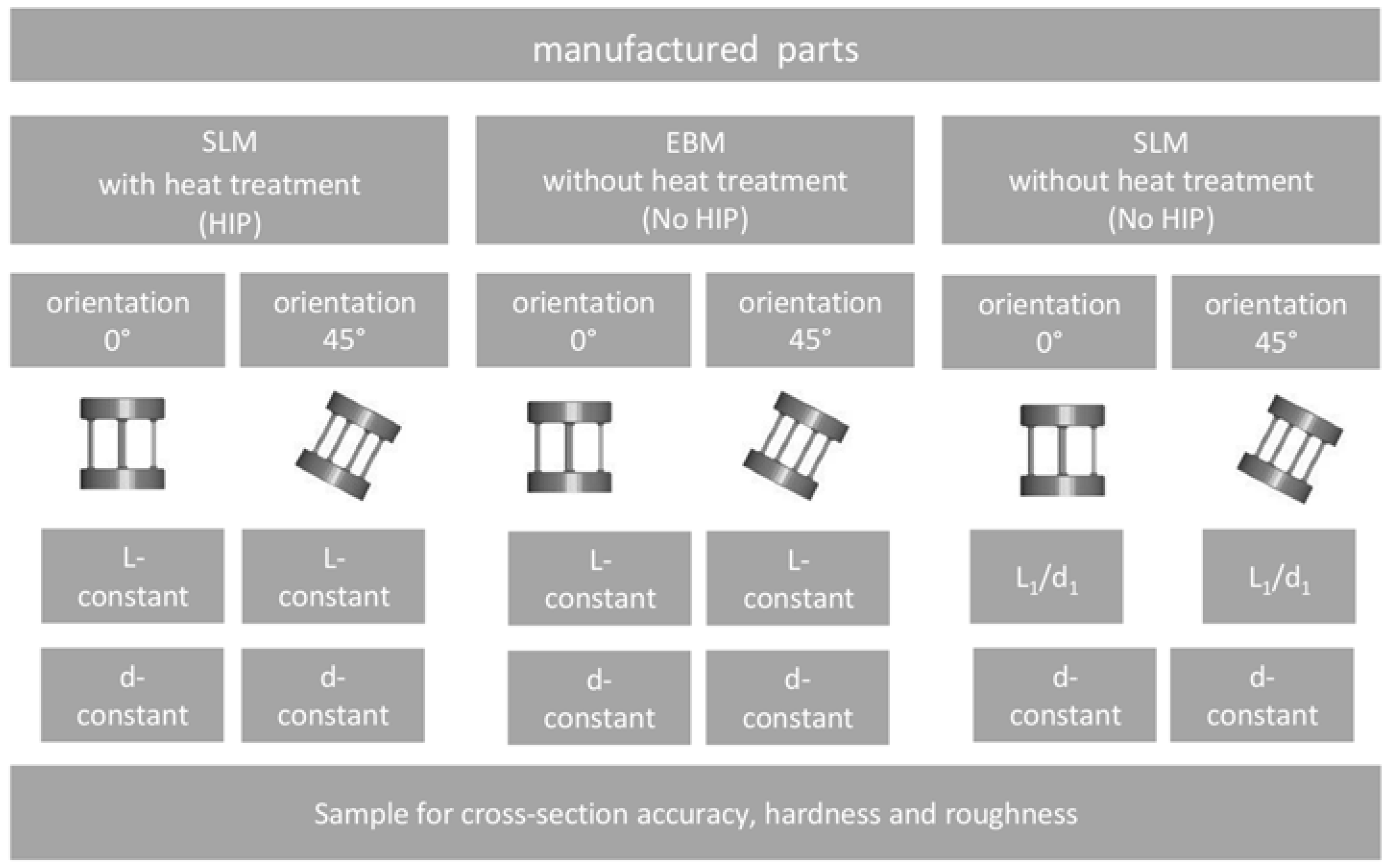
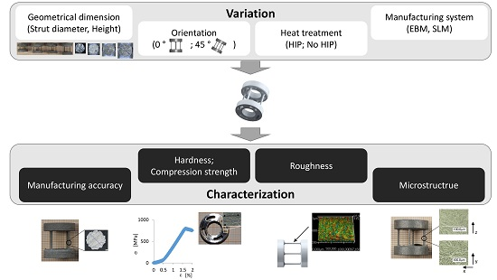
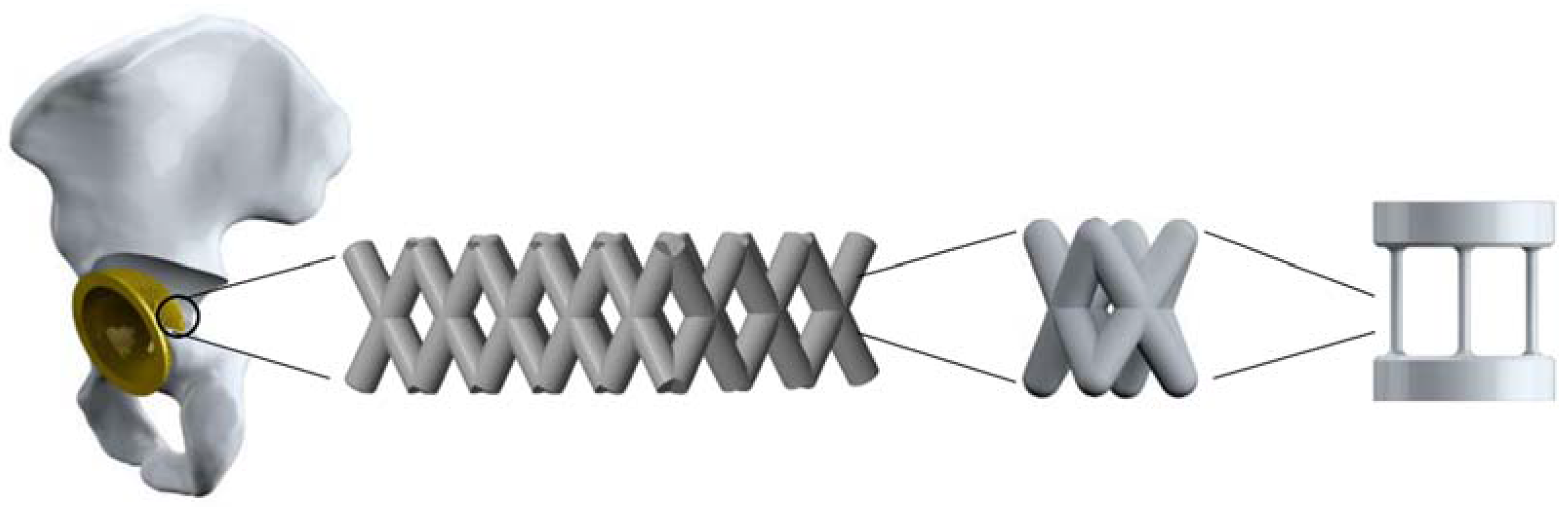
2.1. Parts Design and Configuration

The specimens for mechanical testing within this study were designed using CAD software (PTC Creo, Version 2.0, Parametric Technology Corporation, Needham, MA, USA). The samples are shown in Figure 2. The single strut specimen consists of a base area and a top area. These areas are important as supports during part manufacturing and for reworking (face cutting to obtain two parallel surfaces) after additive manufacturing. In both areas, there are punched-out clearances to reduce the material fraction and the energy applied during manufacturing. The single struts are positioned between these two areas. All parts are designed with four symmetrically arranged single struts. For the determination of the mechanical characteristics in the compression test, the dimensions of the strut specimen were modified in two ways. The geometric parameters for the investigated strut specimen are listed in Table 1.

2.2. Fabrication of the Scaffolds via the SLM Process and the EBM Process
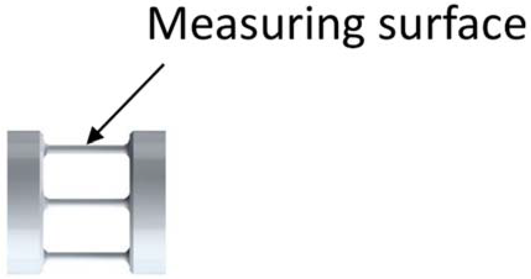
In this work, all parts were built via the SLM process and the EBM process. Figure 3 shows the experimental design. The aim of the experimental plan was to obtain the greatest possible information from the smallest possible number of tests. Figure 4 shows representative parts of the two manufacturing processes in association with building orientation.
Based on the datasets of the CAD samples, all scaffolds were fabricated via selective laser melting using titanium powder (Ti6Al4V) under an ultra-pure argon atmosphere. The powder complies with the requirements of ASTM F 67 and has a determined mean particle size of 43.5 µm. The parts were fabricated with the SLM 280 by SLM solutions GmbH, Lübeck, Germany, using a continuous-wave Ytterbium fiber laser. All parts were built using an identical energy density (J/mm³). The energy density E is defined by the following equation [41]:
E = P v   ×   d × t
where P is laser power, v is scan speed, d is hatch spacing and t is layer thickness.
All parts were built on a substrate plate with a support structure and in the same orientation. The samples were heat-treated under hot isostatic pressing conditions after fabrication and were subsequently removed from the substrate plate. The heat treatment was performed at 920 °C under a pressure of 1000 bar for a duration of 120 min under an argon atmosphere by Bodycote Hot Isostating Pressing, Bruxelles, Belgium. The support structures were removed mechanically by hand. One manufacturing series without heat treatment was removed from the substrate plate for a comparison with the EBM-manufactured parts.
The electron beam melting system A1 by Arcam AB, Mölndal, Sweden, was used to build the parts for compression testing and for comparing the values with the parts made by SLM. The process was carried out using Ti6Al4V powder from Arcam AB with a mean particle size of 70 µm. The chamber, where the powder is applied and melted, was evacuated until a pressure of 5 × 10⁻⁴ mbar was reached and a layer thickness of 50 µm was chosen. The process consisted of a preheat theme and a melt theme. The preheat theme sinters the powder prior to melting it for stability reasons [42]. A comparison with SLM of the process parameters (Table 2 and Table 3) is not easy since scan speed and beam current (i.e., beam power) change during the process due to various algorithms such as the thickness equation, turning point or speed function. However, an average energy density can be calculated for comparative reasons.

2.3. Measurements

A digital microscope—Keyence VHX 2000 (KEYENCE Deutschland GmbH; Neu-Isenburg, Germany,)—was used for the determination of the manufacturing quality, in particular, of the real cross section of the parts and of part dimension. For each orientation and diameter variation, the cross sections were measured. For this measurement, the struts from one part were removed and imbedded in resin. The surfaces were polished, and after a measurement, some µm from the sample were removed for a new measurement. This part was produced together with the parts intended for the pressure test. Every result for the cross sections consisted of 10 measurements. For a qualitative judgment, the external diameters as well as the inner diameter of a circle were determined in the cross section (Figure 5).
Surface quality measurements (Figure 6) were performed with a 3D digital laser-scanning microscope VK-X260 (KEYENCE Deutschland GmbH; Neu-Isenburg, Germany) according to ISO 25178. Ra, as the arithmetic average of the absolute values, and RZ, as the maximum height were determined, respectively, for the SLM and EBM parts in both orientations (0 and 45°). Measurements were carried out on all four struts of a part after manufacturing before the mechanical testing on the outside of the struts. At a measurement length of 4 mm, the λC used was 0.25 and the number of measurement lines was 9. The distance between the lines was 40 µm.
Representative samples were prepared to obtain information on the microstructure. Polished samples were etched by immersion in a mixture of 100 mL H2O, 3 mL HNO3 and 3 mL HF. The microstructures were examined under the digital microscope—Keyence VHX 2000.
In order to study the mechanical properties of the produced samples, two mechanical tests were performed:
(1) All scaffolds were mechanically tested via uniaxial compression according to DIN standard (DIN EN 50106). A universal testing machine (INSTRON E 10,000; Instron GmbH, Darmstadt, Germany) was used to conduct the mechanical testing. Compression testing of the samples was performed with a constant traverse velocity of 2 mm/min. The strain rate for the present results is approximately 1.6 × 10⁻² s−1. All tests were performed under standard atmospheric conditions (24 °C, 50% rel. humidity). The parts were tested with the rods oriented perpendicular to the load direction. The top and bottom areas of the specimen were aligned parallel to the load bearing capacity. Values for load and displacement were continuously recorded during testing. All fabricated scaffolds were tested with five specimens until mechanical failure occurred.
Evaluation was always based on the cross section area A determined with the digital microscope and the maximum load F before the first fracture or decrease in load occurred.
Based on these data, the compression strength was determined as
σ =   F A
All determined strengths were considered with respect to the slenderness ratio λ. The slenderness ratio λ was determined as the quotient of the product of column effective length factor β times Length of the strut L and gyration radius i. The column effective length factor for all calculations was 0.5, equivalent to the Euler loading case 4.
λ =   β × L i
The gyration radius i was calculated as root of the quotient of the geometrical moment of inertia I and the cross section area A.
i =   I A
Based on the strut cross section areas determined, the equivalent diameter (Figure 7) was used to calculate the gyration radius. The equivalent diameter matched the diameter of a comparable circular strut and was calculated from the results for the cross section areas determined with the digital microscope—Keyence VHX 2000.
(2) Vickers hardness HV 10 (according to DIN standard—DIN EN ISO 6507-1) was measured on both sites of the back and top areas of the specimen (Figure 8) using the hardness tester, Zwick 3212.002 (Zwick GmbH Co KG, Ulm, Germany). The parts were tested with a test load of 98.07 N within a test time of about 10 seconds. On average, 10 indents per surface were taken for each condition. Prior to the measurement of the back and top areas, the part was face cut (between 10 and 50 μm) to achieve a practical reference surface.

2.4. Statistical Analysis

All data are expressed as means ± standard deviation (SD). The association between the geometrical influences (length and diameter of the strut as well as the slenderness ratio λ) and the compression strength was assessed by linear regression. All statistical analyses were performed using SPSS, software version 22 for Windows (SPSS® Inc. Chicago, IL, USA). A two-sample t-test was performed to statistically examine significant differences between the means. This test was used for measuring the hardness of manufactured parts dependent on manufacturing type and heat-treatment variation. Moreover, the test was performed for determining the surface quality of SLM and EBM parts. Differences of p < 0.05 were considered as statistically significant.

3. Results and Discussion

In this study, parts were built using two additive manufacturing processes. To characterize the influence of the processes, of the orientation and of a heat treatment of the part on mechanical properties, the geometrical dimensions as well as the orientation in the building process was varied. The obtained results are presented and discussed in the following chapter.

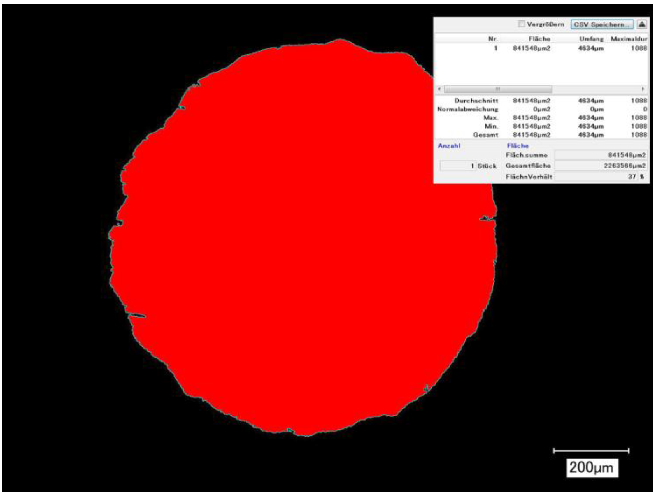
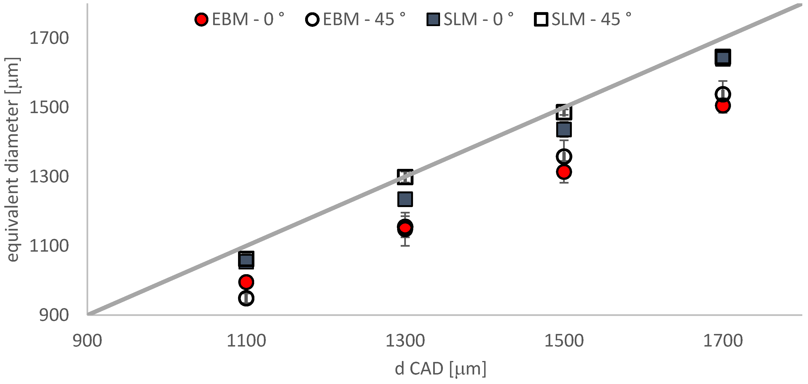
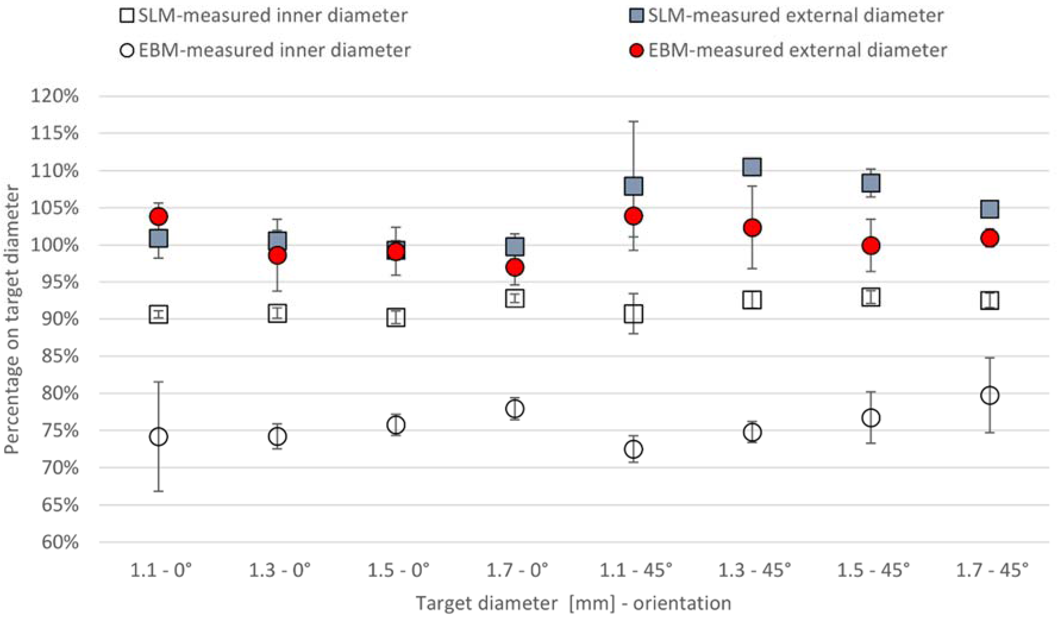
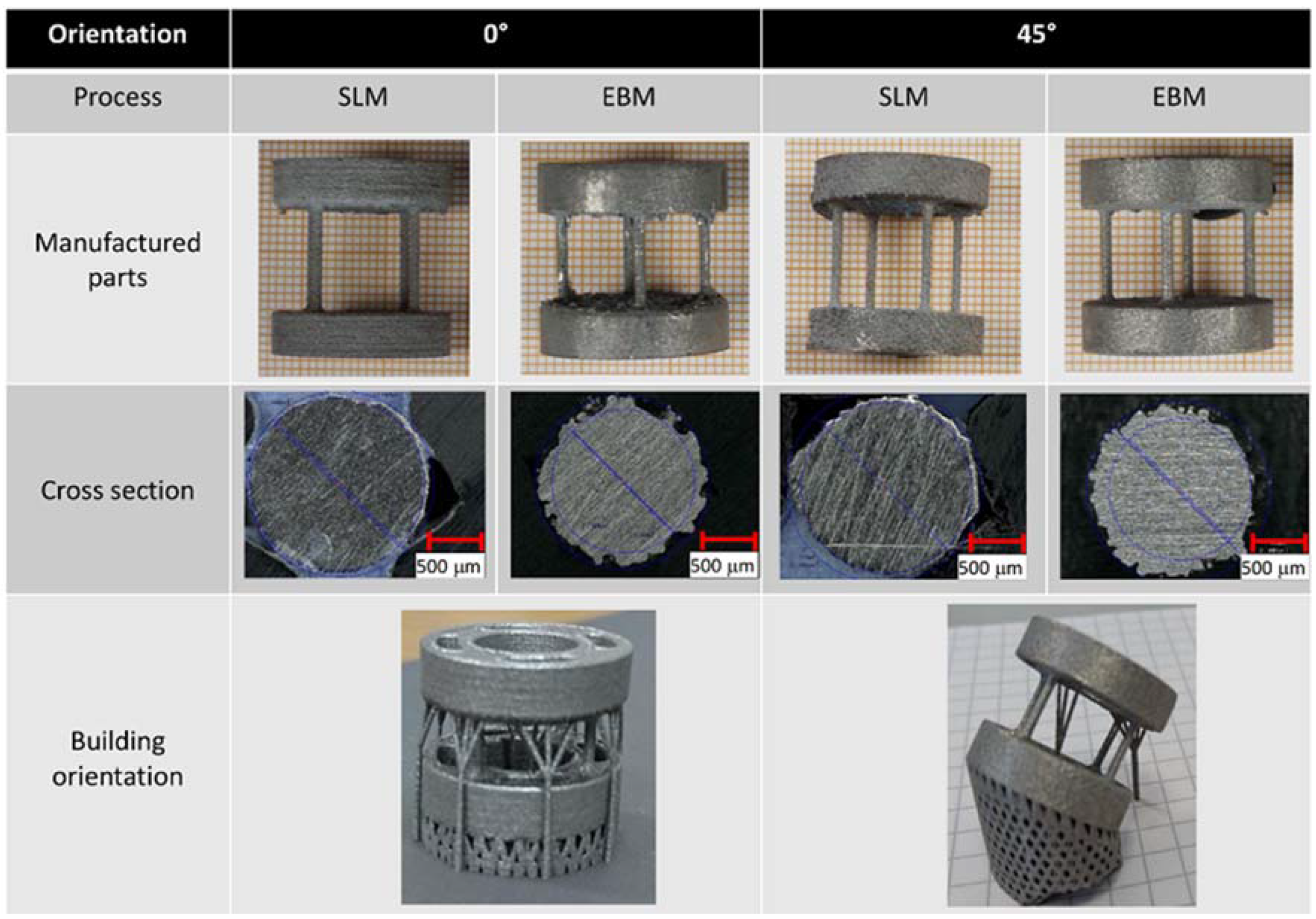
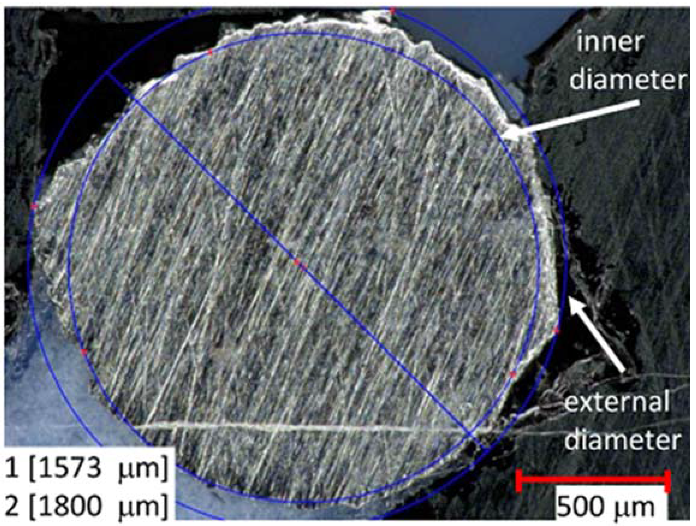
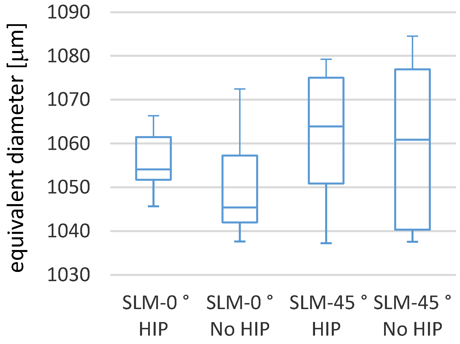
3.1. Cross-Section Accuracy of Fabricated Struts

Table 4 lists the results of the manufactured and measured SLM- and EBM-processed parts. Figure 9 shows the estimated equivalent diameters and Figure 10 shows the inner and external diameters of the SLM and EBM parts in dependence on diameter and orientation.
All SLM parts have smaller equivalent diameters than the CAD target specifications. In all variants, the components from the SLM process are closer to the target specification than the EBM-manufactured parts. Although using a scaling factor to obtain the proper geometries in accordance to the CAD specifications, the EBM parts differ between 10% and 12% from the CAD data specifications in the zero degree orientation. In the 45-degree orientation, the deviation is 9% to 14%. SLM component deviations in the zero-degree orientation are between 4% and 5% while the deviations in the 45-degree orientation are between 0% and 3%. SLM components show minor deviations.
As shown in Figure 4, the additively manufactured struts deviate from the ideal circular shape. The measurements of the inner circle in the maximum permissible orientation as well as of the possible external circle diameter offer an interesting insight on manufacturing quality. The struts produced using SLM show smaller deviations than the EBM-manufactured struts. The 45-degree oriented samples are always larger than the 0-degree oriented samples. While the large outer cross-sections of the 0-degree oriented samples very slightly differ from the CAD data specifications, the differences from the desired values shown for the 45-degree oriented samples are significantly larger. The deviations of the outer diameters tend to be smaller with increasing nominal values. The supporting cross-sections also increasingly approach desired specification values with larger diameters. Large measurable diameters increasingly tend towards zero deviation. The deviations are process dependent and lead, in particular at 45 degrees, to an enhancement of the effect.
The deviation of the 45-degree oriented specimens from a circular shape as seen in Figure 4 leads to an increase in the outer diameter. The more pronounced splitting of the surface in the EBM process clearly reduces the coherently formed material area in the interior of the strut. Thus, while the values measured outside are closer to CAD data specifications than in the case of the SLM samples, the internal structures nevertheless deviate more measurably from the desired dimension.

Comparison of SLM Manufactured Parts with and without Heat Treatment

The fabrication accuracies determined in Section 3.1 were identified for the samples originating from the series named in Section 2.1. These were the heat-treated SLM samples and the EBM samples without heat treatment. The influence of heat treatment in combination with an effective pressure (HIP) on component accuracy was then determined (Figure 11). Compared were SLM specimens with diameters according to the design specification of 1.1 mm in the orientations 0° and 45°. Special emphasis was again placed on comparing post-treatments using heat and pressure (difference between HIP and No HIP).
A two-sample t-test was performed to statistically examine significant differences between the means. No statistically significant difference was determined when the results were compared. It can be concluded that the treatment of the SLM-produced samples with HIP treatment has no effect on the manufacturing precision of the manufactured items. The results listed in Section 3.1 (SLM with HIP) are transferable to the SLM-manufactured samples without HIP treatment. It also allows the conclusion that a HIP process has no influence on the stability of the diameter of the EBM samples.

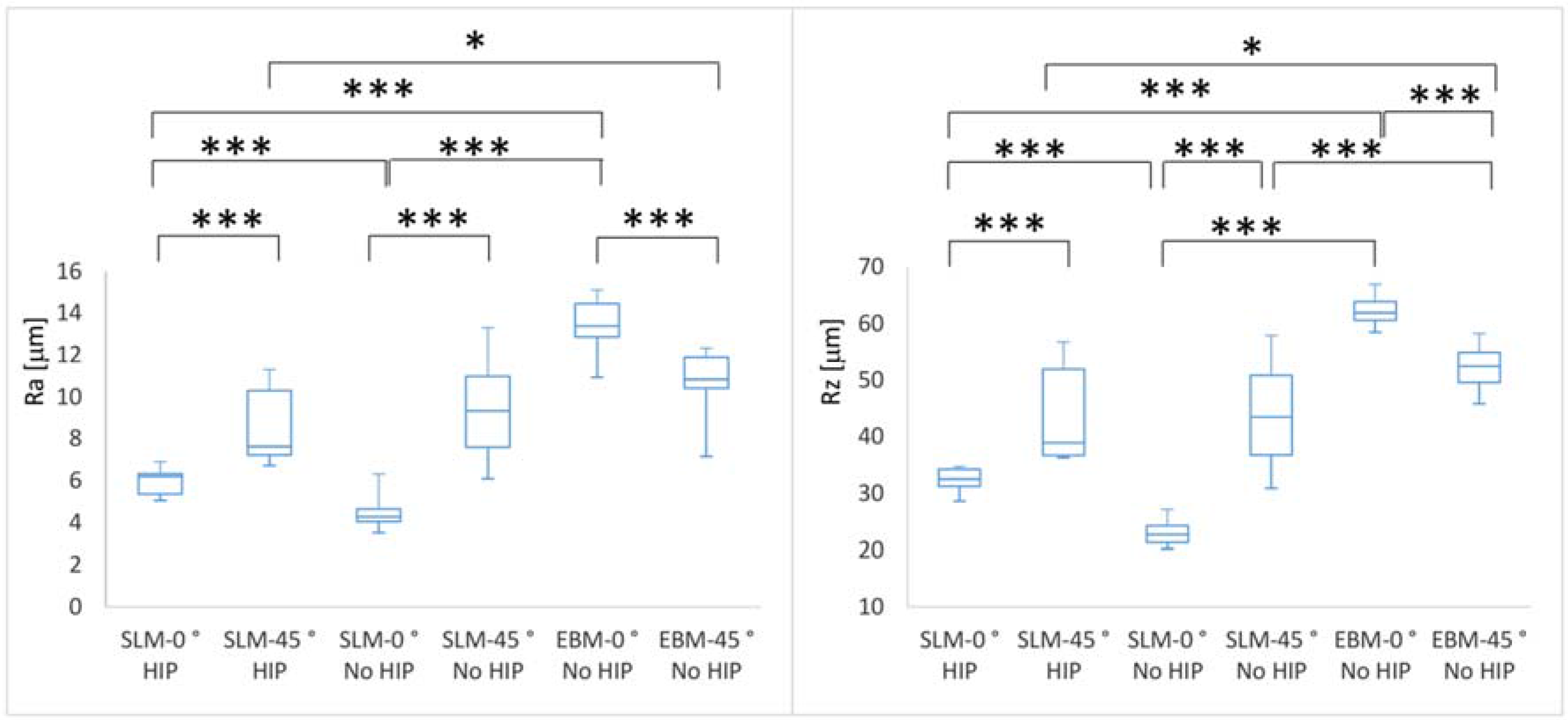
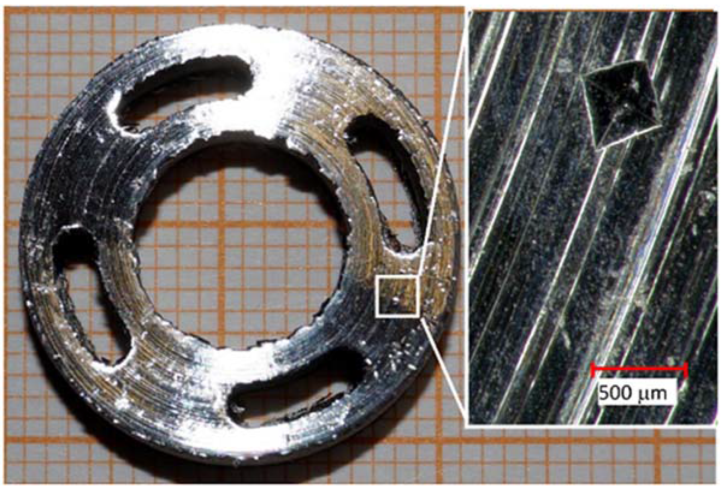
3.2. Surface Quality

For the qualification of the outer as-built surface quality of the struts, a roughness measurement was carried out. The roughness values Ra and Rz were obtained, as shown in Figure 12.
The roughness Ra of SLM-manufactured (HIP and No HIP) parts was significantly (p < 0.001) lower in the 0° orientation than in the 45° orientation. The EBM parts showed the opposite behavior. Here, the Ra values in the 45° orientation are lower than in 0° orientation. As Suard et al. [34] have described, surface roughness and the resulting strut shape depend on the orientation during the building process. Whereas vertically oriented struts display uniform roughness values, a horizontal or oblique orientation leads to increased roughness. The reason is the energy flow into the powder bed. Due to this energy flow, powder particles repeatedly tend to adhere to the struts on the underside. This phenomenon causes deviations from the present geometry as well as porosity deviations. The effect of powder adhesion is also described in [43]. This phenomenon causes differences in the roughness as a function of the orientation. The SLM parts have a higher roughness Ra of the 45° oriented parts because particles adhere on the strut side facing the powder bed. On EBM parts, the same phenomenon leads to a lower roughness of the 45° oriented parts. The particles that adhere on the surface decrease the roughness because some unevenness gets filled.
Fox et al. [44] found in their work a shift between surfaces dominated by partially melted powder particles and surfaces dominated by material from the re-solidified melt track. With a decrease of the surface angle, the Ra value increased. A decreased surface angle is equivalent to the 45° in this work. The 0° orientation in this work means a higher surface angle. These results are consistent with the previous results of Triantaphyllou et al. [45] who found differences between upskin and downskin surfaces as well as the orientation angles. The differences in average roughness Ra found between the EBM and the SLM method are also confirmed here.
There is a significant difference between the SLM parts (HIP and No HIP) in the 0° orientation (p < 0.001). In production this difference, however, is likely to be within the accuracy fluctuations range. The roughness Ra of SLM-manufactured (HIP and No HIP) parts were significantly (p < 0.001) lower for the 0° orientation than for the EBM parts. In the 45° orientation, the roughness was only different between SLM HIP and EBM (SLM HIP < EBM; p < 0.05). These relationships are also seen for the roughness Rz.
The values obtained for SLM- and EBM-manufactured Ti6Al4V parts correspond to those from the literature. Accordingly, the SLM-parts show a far lower deviation from a theoretical smooth surface that can be considered an indicator for a stable and accurate manufacturing process. Besides powder size distribution, the layer thickness in the powder feed and the powder bed system, the laser beam diameter itself has an influence on surface roughness [13]. Higher roughness values of EBM parts are typically due to the process parameters. A smoother surface and therefore lower roughness is therefore possible through the optimization of process parameters.

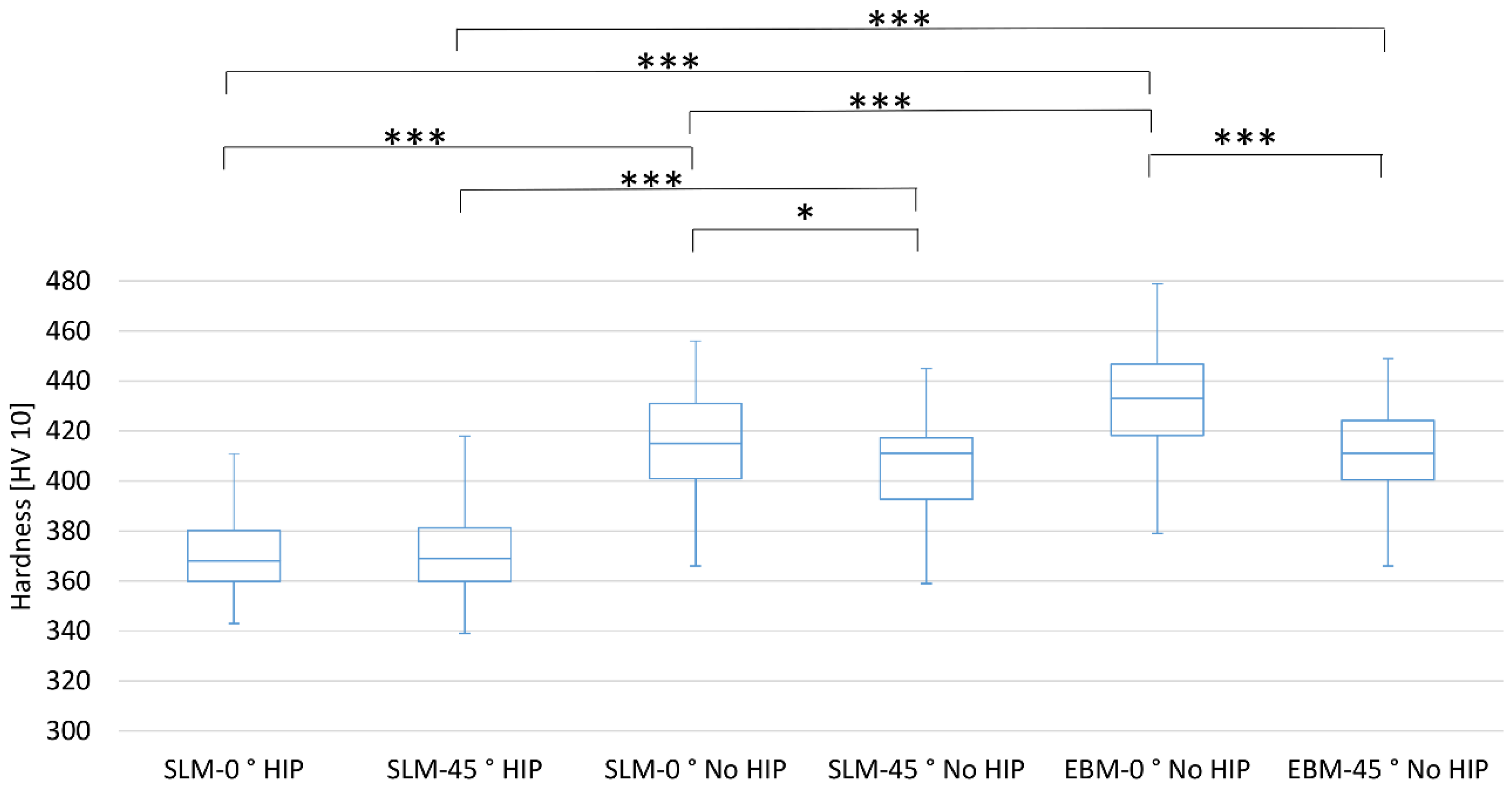
3.3. Vickers Hardness

The hardness of parts manufactured in the 45° orientation were significantly (SLM-No HIP p < 0.05; EBM-No HIP p < 0.001) lower than in those manufactured in the 0° orientation. This correlation is not seen in the heat-treated SLM-manufactured parts. Heat treatment of the SLM-manufactured parts led to a significantly lower hardness (in both orientations p < 0.001). When SLM- and EBM-manufactured parts with no heat treatment were compared, the SLM parts had in both orientations a significantly (p < 0.001) lower hardness than the EBM parts. The results for hardness are shown in Figure 13.
The values determined for hardness correlate to values found in the literature [38,46,47]. By Song et al. [13] was shown that mechanical properties depend on the processing parameters. The determined value for hardness for a perfect SLM-manufactured part without heat treatment was 450 HV. Murr et al. [48] have shown the differences between the selective laser melting and the electron beam melting process and the influence on the mechanical properties, especially hardness. Hardness values for EBM-manufactured parts were found in the range of 410 to 427 HV. Wu et al. [49] investigated the positive effect of hot isostatic pressing on the improvement of the anisotropies of bending and impact properties. They found that hot isostatic pressing and building direction affect mechanical properties. While the as-built parts have a hardness of 41 and 42 HRC, the HIPed parts have a hardness of 34 HRC. In the work of Wu et al. the influence of the HIP process is greater than the orientation in the building process. The phase transformation of the α′-martensite to α + β structures is an essential reason for the differences in mechanical properties.
These results, show in comparison with each other, that a hardness typical for Ti6Al4V material and additively manufactured parts was achieved. In addition, this elucidates that, as a complementary measure, hardness measurement is excellently suited as a qualitative manufacturing control. Significant differences are caused mainly by the differences in the structure. The heat-treated parts consist predominantly of a microstructure with an α phase and a lamellar β phase (brighter than the α phase). The primary α phase was distributed along the prior β grain boundary. The structure is uniformly built and aligned parallel to the building direction (Figure 14) in the 0° orientation.
In the 45° orientation (xz plane) as well in the 0° and 45° orientation (xy plane), this alignment is not seen. It seems that all microstructural anisotropy was eliminated. The parts that did not receive any heat treatment after manufacture, showed a primarily acicular martensitic alpha (α′) and fine lamellar beta (β) microstructure. The β grains appear to be brighter and the α′ grains darker. This microstructure and its inhomogeneity was the result of fast heating and cooling during the process. The prevailing α′ grains grew almost parallel to the building direction. This is visible in both the 0° and 45° building directions. Parts with α′ grains in comparison to parts without α′ grains have a higher hardness. The higher hardness of the α′ phase as against the α + β structures is typical for this structure. The representative cross-section microstructures in Figure 14 confirm these relationships. The HIPed SLM parts show a uniform α + β structure with a clearly visible building orientation only in 0° orientation. The as-built parts, however, show a clearly oriented structure (in xz plane and in xy plane) with acicular martensite. The higher hardness of the 0° oriented parts is the result of the better and uniform orientation of the α′ grains (martensite). In the 45° oriented parts, the structure is more irregular. This leads to a smaller resistance to an applied compressive force, because the 0° oriented struts are vertical to the acting force. The force required to overcome the resistance is then greater.

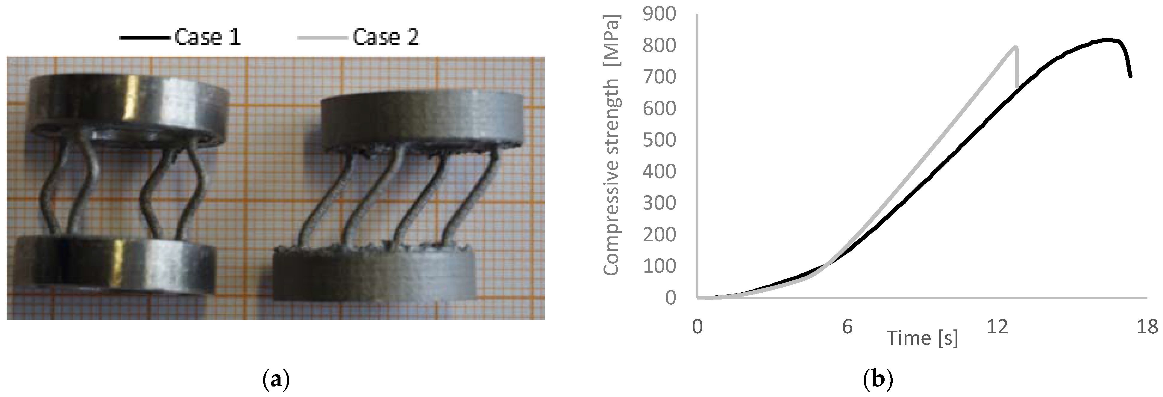
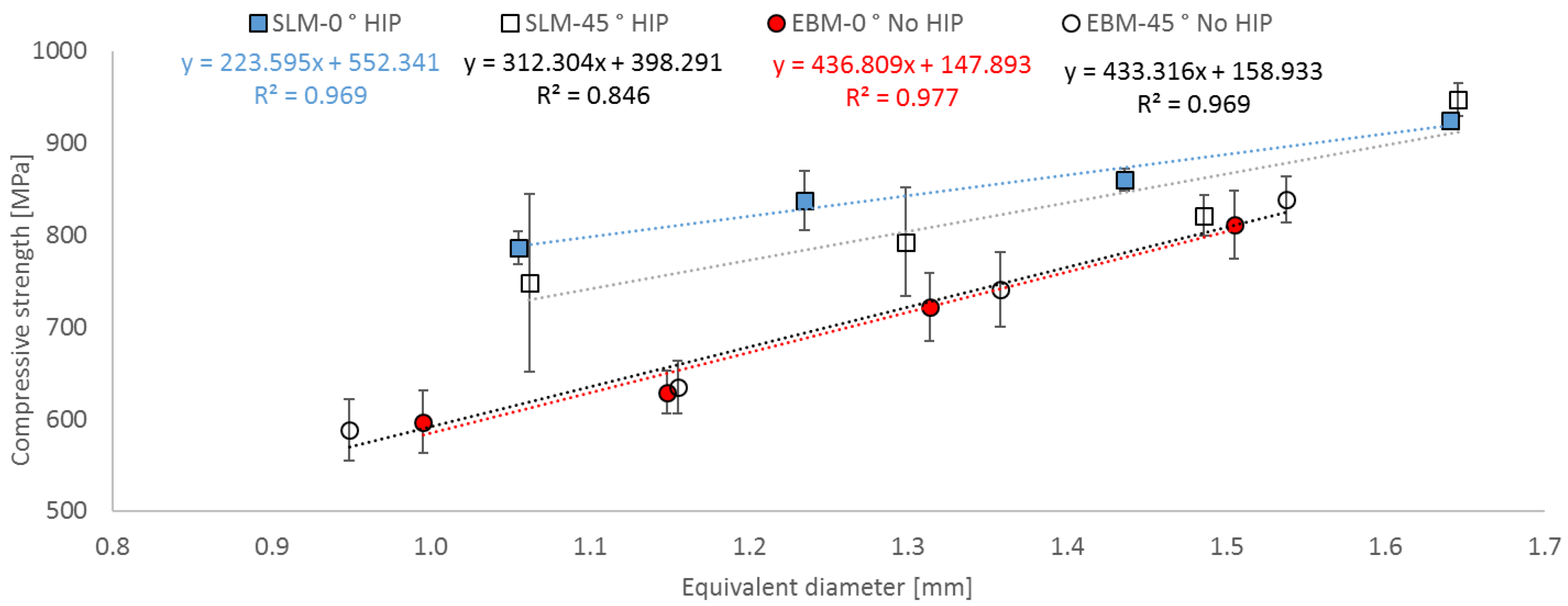
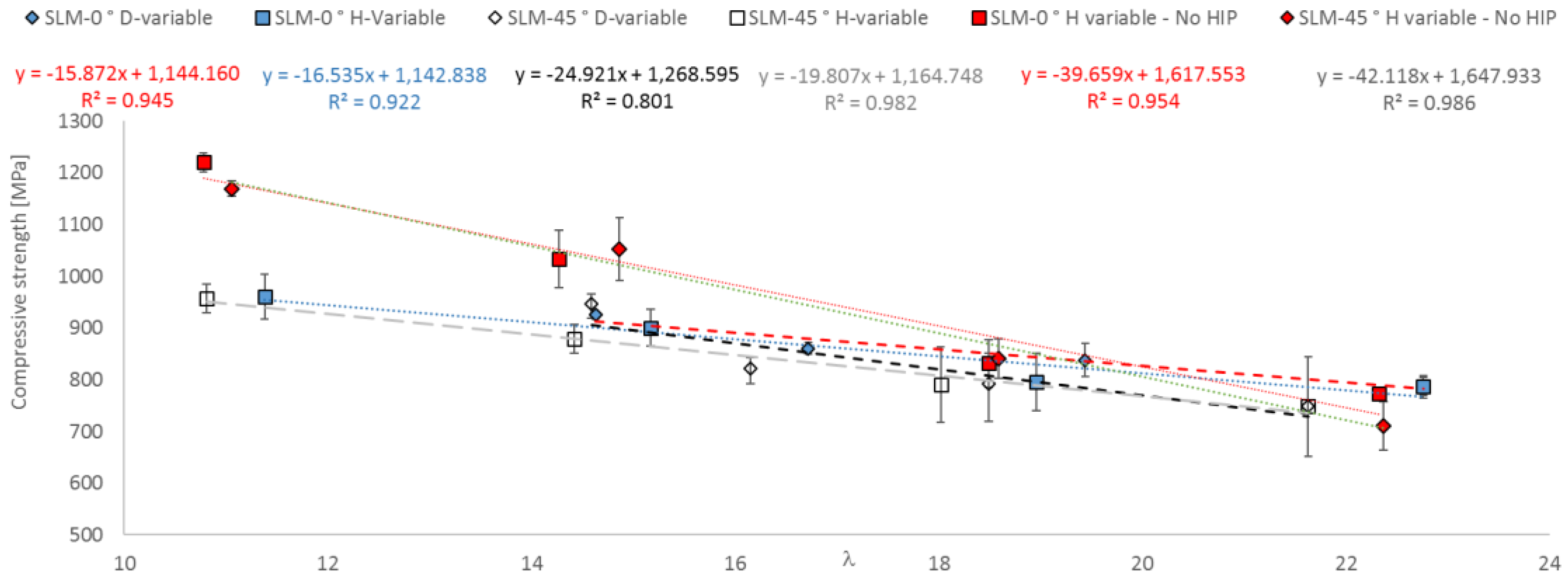
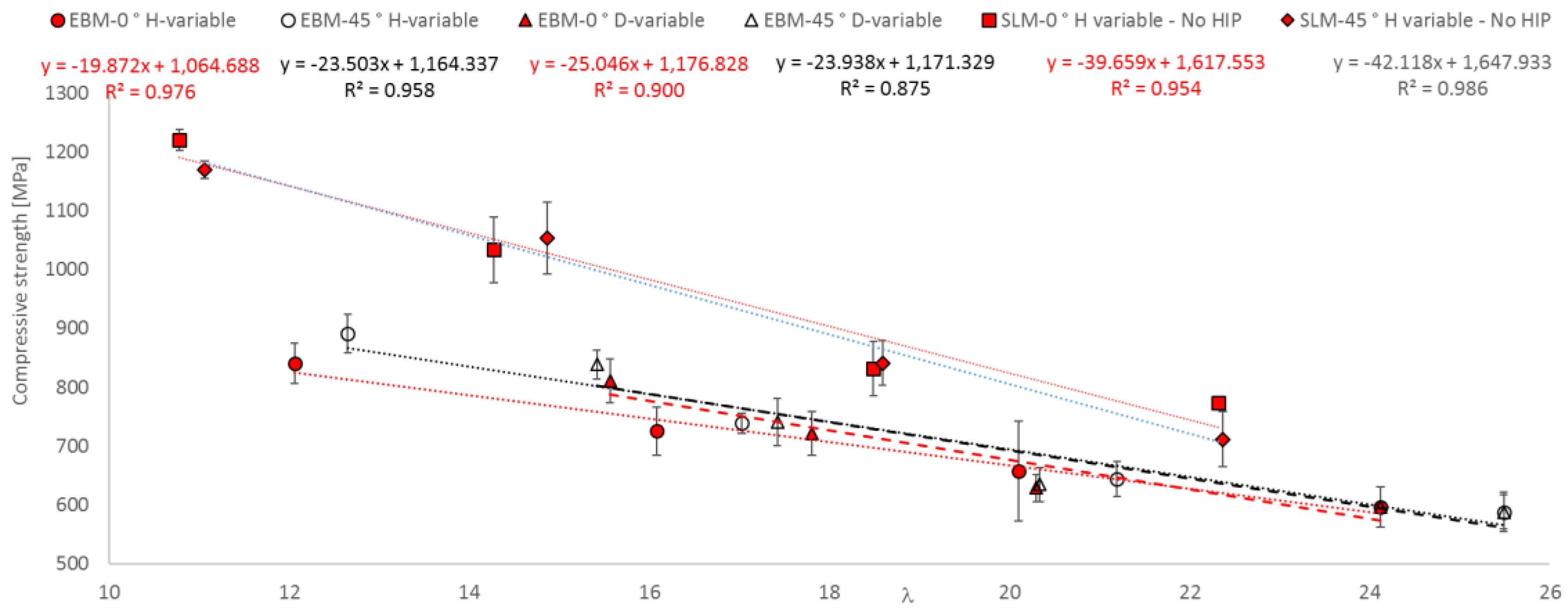
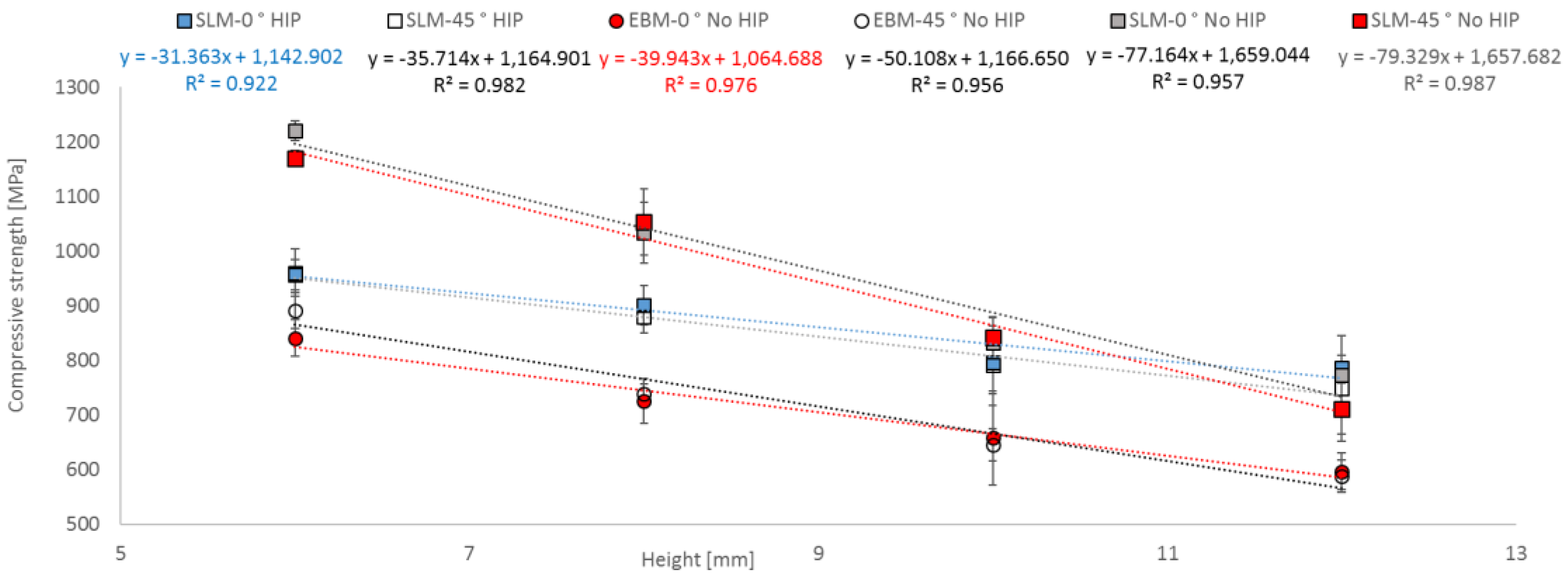
3.4. Compressive Strength as a Function of Geometrical Parameter

All fabricated parts were tested until the maximum possible load was exceeded. The samples showed two types of failure behavior independent from the output quantity.
Figure 15 shows representative examples for failure behavior. In Table 5 are listed all tested samples that were considered for the evaluation of results.
The compression tests performed in this work on these specimens lead to the deformations as shown in Figure 15. As specified by the Maxwell criterion (M < 0), the occurring deformations are typical for flexure-dominated structures [36]. According to the literature, the stability failure of the rod-like elements that are present in the specimens under investigation can be explained by differing buckling behaviors (load cases). Load cases showing this are known. The deformations that have occurred here are clearly assignable to such known load cases. While Case 1 showing the typical deformation for symmetrical buckling, Case 2 is an example for antimetrical buckling. As described by Sattler [50], the path of the deformation is the curve of a parabola. The same buckling length coefficient that is of interest for determining the slenderness ratio applies in both cases. For the deformation pattern, similar results were found by Ushijima et al. [33] in their theoretical considerations of compressive properties. The stability failure in both the natural modes shown is characterized by an abrupt event.

Case 1: (long curve)

Here, the strain gradually and steadily increases, reaches a short plateau until it abruptly decreases. This can be caused by imperfections (due to quality deficiencies during manufacturing) that lead to a reduction in the stiffness.

Case 2: (steep abrupt decrease)

The strain increases and, after exceeding the stability limit, abruptly drops.
In Case 2 stability failure occurs at a higher stiffness level than in Case 1 (strain increase is steeper than in Case 1). The imperfections in Case 2 have a lower influence on stiffness (i.e., the stiffness based on the material-dependent elastic modulus and the manufacturing dependent property) until the stability limit is abruptly exceeded.
The failure types described occur independently of geometric variation and orientation in manufacturing. The required maximum loading to exceed stability and thus compressive strength remains similar. The established results provide evidence that regardless of geometrical considerations (different heights, diameters) and the method (EBM, SLM) the determined deformation behavior is characteristic of the specimens under investigation. It remains unclear how great the influences are that are caused by probable deviations of rod positions from the acting load (plane parallelism) or by production-related faults (e.g., the crossover between the base and top area of the rod). Just as interesting would be any functional associations between the orientation of the specimens tested and the level of influencing imperfections.
Figure 16 shows the relation between equivalent diameter and compression strength.
Both manufacturing systems in principle behave identically. Compression strength increases as expected with increasing equivalent diameters. SLM parts showed higher compression strength values than the EBM parts. While the difference between the orientations of the EBM-manufactured parts is not relevant, the difference in the SLM-manufactured parts is clearly visible.
A linear relationship was found between equivalent diameter and compression strength. EBM parts in both orientations showed a high correlation (0°—R2 = 0.977; 45°—R2 = 0.969). In contrast, the SLM parts in the 45° orientation showed a lower correlation (R2 = 0.846). The correlation in the 0° orientation is provided in the range of the EBM parts (R2 = 0.969).
As shown in Figure 10, it appears that the specific manufacturing accuracy of the struts (diameter) has an influence on the course of the results. EBM parts showed the same course in results, especially in the measured inner diameter. This area is the most important area for the acceptance of loading force. The values for 0° and 45° oriented parts are comparable. The SLM parts however show differences in the 0° and 45° orientation. The differences in the 45° orientation are greater than in 0° orientation. This provides clear information that the compression strength value is definitively affected by the area of the strut that can hold the acting force in a clear defined structure of a circle. This was compared to Suard et al. [34] who have described the influence of the diameter on mechanical properties. It confirms that strut orientation in the manufacturing process influences the formation of the surfaces and thus also the roughness. This increase in the roughness Ra of the SLM specimens leads to a reduction in the cross-section and thus to a low compressive strength.
Figure 17 showed the relation between height and compression strength.
SLM- and EBM-manufactured parts in principle showed an identical behavior. Compression strength decreased as expected with increasing height. SLM parts showed higher values for compression strength than the EBM parts. The differences between the orientations of the EBM-manufactured and SLM-manufactured parts are small.
A linear relationship was found between equivalent diameter and compression strength. EBM parts showed a high correlation in both orientations (0°—R2 = 0.976; 45°—R2 = 0.956). SLM parts also showed a high correlation in the tested orientation (0°—R2 = 0.922; 45°—R² = 0.982). The correlation of the SLM parts without heat treatment was within the range of all other parts (0°—R2 = 0.957; 45°—R2 = 0.987).
The differences between HIPed and No HIPed parts that affect the mechanical properties are well-known [40,46,51]. Especially HIPing leads to decreased strength. The reason is the transformation of martensite into α and β phases. The marginally lower strength is characteristic for the α + β phase. This correlation applies to the SLM parts. The difference between HIPed and No HIPed parts dwindles away with increasing height until it is gone.
Although the EBM samples achieved higher values in the hardening measurement, the compressive strength values are below the values for SLM samples. Here lies the reason for the significantly higher roughness RZ and Ra of the EBM parts. Kasperovich et al. [46] described that the rough “as-built” surface needs to be considered as crack initiator and that its lower strength has to be taken into account. This leads to lower compression strength of EBM parts compared to SLM parts without heat treatment.
The influence of the geometric conditions can be described very well by indicating the degree of slenderness λ (see Equation (3)). The correlation between the compressive strength and the slenderness ratio also revealed linear dependencies with high coefficients of determination of over 90% as shown in Figure 18 and Figure 19. The coefficients were lower only in two cases (45° oriented parts with variable d).
Compressive strength increased with a decreasing slenderness ratio for all tested variations. The slopes show, that the possible change in compressive strength by variations in the geometrical parameters (diameter or height) leads at least to the same result in the case of the HIPed parts. The results from the No HIPed parts differ clearly from the HIPed parts. Here is seen a more different behavior. Nevertheless, the relation between the obtained mechanical properties and the geometrical properties is well described with the linear relationships found.
These results show that the orientation of the part during the building process plays an important role in view of mechanical properties. The 45° oriented parts show by variation of the diameter a direct influence on the mechanical properties. The influence of a modification in the diameter is greater than a change in the height while retaining the same slenderness ratio. A good indicator for this are the different slopes in the correlations found. The influence of orientation on the microstructure and on the mechanical properties is known [19,25]. This influence also becomes clear here. With increases in the diameter, the proportion of the structure-oriented structural areas also grows. These obliquely oriented structural regions can absorb increasingly less load. For the 0° oriented samples, it is less important whether the diameter is increased or the height is varied.
The difference between the SLM parts (HIP and No HIP) is clearly caused by the microstructural difference. The HIPed parts have a uniform α + β structure with a lower hardness than the No HIPed structure with a martensitic fraction. This relationship is also seen for compression strength.
In the EBM parts, the compressive strength also increased with a decreasing slenderness ratio for all tested variations. Here is noteworthy that the 45° oriented samples behave similar. Regardless of whether the diameter or the height varies, the result is the same. However, differences are seen in the 0° oriented samples. Here, a change in the diameter has a greater effect on changes in the mechanical properties than a change in height. The EBM samples deviate more and more from the default (dCad) in their measured outer diameter (Figure 10). Since all EBM samples were produced without heat treatment, a direct comparison with the SLM samples (0° and 45°) is possible here. The EBM samples, though achieving higher values in the hardness measurements, have in comparison to the SLM parts (both without heat treatment) the lower compressive strength. The reason lies, as already explained, on the significantly higher roughness values RZ and Ra of the EBM parts. The crack initiation of the rough “as-built” surface leads to a lower compression strength of EBM parts.

4. Conclusions

The properties of single Ti6AL4V struts fabricated via SLM and EBM were examined experimentally for selected different geometrical dimensions. Two building orientations with variations in the height and diameter of the individual struts were integrated in the tests.
The following specific conclusions have been reached:
  • Cross-section accuracy of fabricated struts
    All manufactured struts deviate from the given diameter from CAD data.
    The SLM parts show a higher accuracy than the EBM parts.
    No geometric differences could be determined between the HIPed and NO HIPed SLM parts.
  • The values of roughness obtained for SLM- and EBM-manufactured Ti6Al4V parts correspond to those from the literature. The SLM parts have significantly lower Ra and RZ values in both orientations.
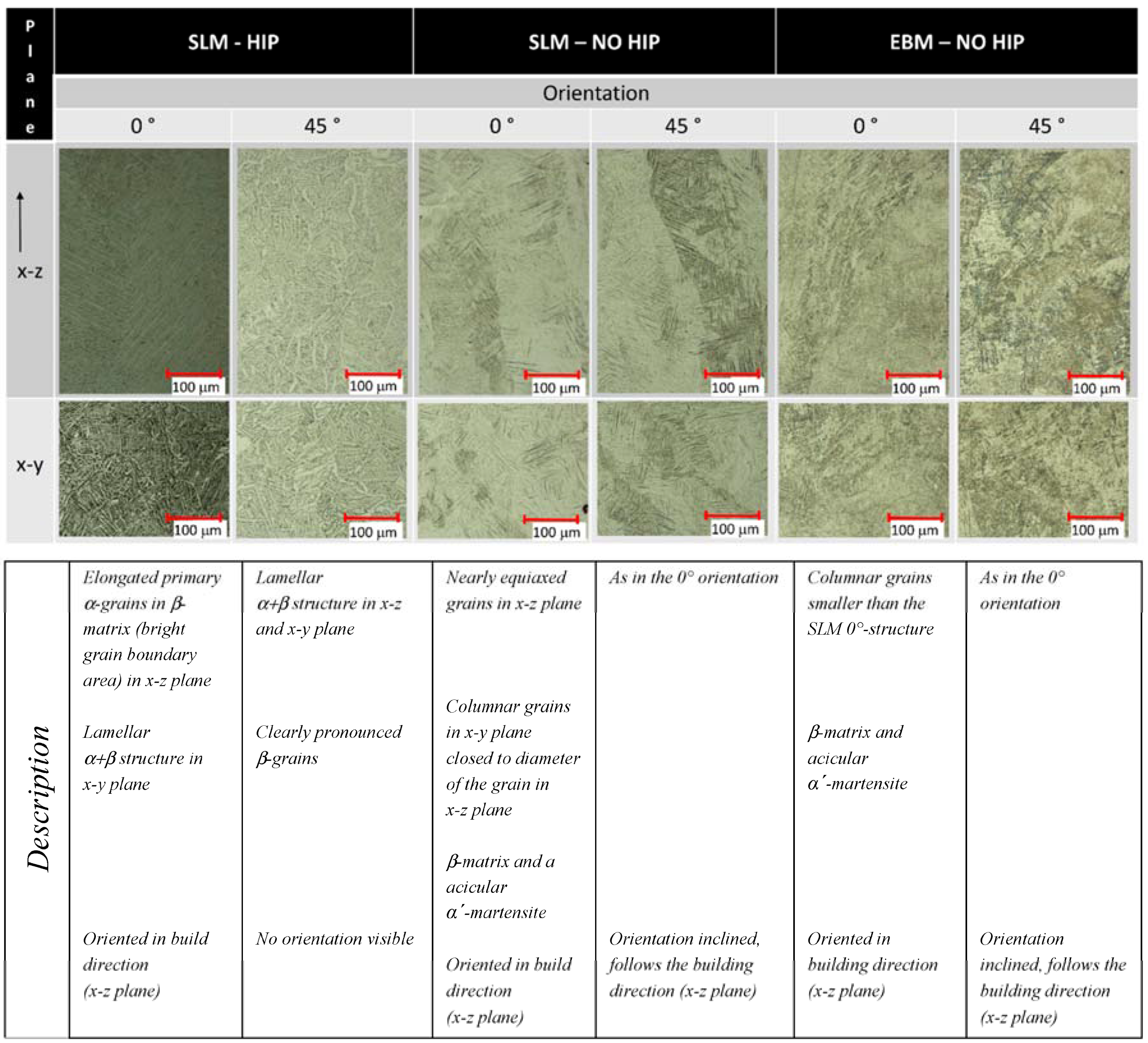
  • Different hardness values between EBM and SLM were determined and supported by their different respective microstructures. The No HIPed EBM parts showed the highest values for hardness. The HIPed SLM parts showed the lowest values according to microstructure. The hardness of the 45° oriented parts without heat treatment was significantly lower than of the 0° oriented parts. Heat-treated parts showed no differences in dependence on the orientation.
  • Based on tests under uniaxial loading conditions, the influence of strut orientation on compression strength was demonstrated.
    A functional correlation between compressive strength and slenderness ratio (λ) as well as between equivalent diameter (d) and height (L) of EBM and SLM parts could be established.
    Modifications in diameter lead to a larger influence on compressive strength than modifications in height.
    A strut orientation of 45 degrees leads to a moderate decrease in the compression strength of EBM and SLM parts.
    Both the microstructure and the cross-section accuracy of fabricated struts as well as roughness are responsible for differences in compressive strength.
    The specimens produced show 2 types of stability failure—symmetric and antimetric buckling—at the same compressive strength levels.
In our work, we could demonstrate the importance of the exact fabrication and what influence the quality of a single strut has on mechanical properties. The results are strongly affected by the microstructure and the roughness of struts. Hardness and compressive strength exactly confirm the dependence of material behavior as a function of orientation. Orientation is a crucial determining fundamental analysis factor of mechanical characteristics and thus forms, taking into consideration geometrical influences, an essential basis for the constructive design of medical-engineering applications in which rod structures are used. The results obtained the influence of the slenderness ratio and especially the influence of the diameter on the mechanical properties provides an excellent basis for a transfer into medical applications. The knowledge gained from the comparisons of the EBM- and SLM-manufactured single struts can be practically applied to problems in the field of additive manufactured parts.
Of special interest are the influences that resulted in the different failure types of the specimens. Both the influences from specimen orientation during mechanical testing as well as from production-caused inhomogeneities need to be regarded separately in future.
Besides compressive stresses, results from bend loading also need to be taken into consideration both in static as well as vibration tests. The results brought forward here represent only a part of the necessary information required for the translation into medical applications.

Acknowledgments

We are grateful for the financial support provided by the Federal Ministry of Education and Research (03FH005IX5).

Author Contributions

We point out that all authors were fully involved in the study and in preparing the manuscript. V.W., P.D. and H.S. designed the study. V. W. generated the CAD samples with support of H.H. and was involved in the manufacturing process of the scaffolds. V.W. and P.D. performed the experiments, analyzed the data with support of N.L. and wrote the initial manuscript. H.H. and R.B. organized the research funding. All authors ensured the accuracy of the data and the analyses and reviewed the manuscript in its current state.

Conflicts of Interest

The authors declare no conflict of interest.

References

  1. Heinl, P.; Müller, L.; Körner, C.; Singer, R.F.; Müller, F.A. Cellular Ti-6Al-4V structures with interconnected macro porosity. Acta Biomater. 2008, 4, 1536–1544. [Google Scholar] [CrossRef] [PubMed]
  2. Geetha, M.; Singh, A.K.; Asokamani, R.; Gogia, A.K. Ti based biomaterials, the ultimate choice for orthopaedic implants—A review. Prog. Mater. Sci. 2009, 54, 397–425. [Google Scholar] [CrossRef]
  3. Hazlehurst, K.; Wang, C.J.; Stanford, M. Evaluation of the stiffness characteristics of square pore CoCrMo cellular structures manufactured using laser melting technology for potential orthopaedic applications. Mater. Des. 2013, 51, 949–955. [Google Scholar] [CrossRef]
  4. Attar, H.; Calin, M.; Zhang, L.C.; Scudino, S.; Eckert, J. Manufacture by selective laser melting and mechanical behavior of commercially pure titanium. Mater. Sci. Eng. A 2014, 593, 170–177. [Google Scholar] [CrossRef]
  5. Attar, H.; Löber, L.; Funk, A.; Calin, M.; Zhang, L.C.; Prashanth, K.G. Mechanical behavior of porous commercially pure Ti and Ti–TiB composite materials manufactured by selective laser melting. Mater. Sci. Eng. A 2015, 625, 350–356. [Google Scholar] [CrossRef]
  6. Wauthle, R.; van der Stok, J.; Yavari, S.A.; van Humbeeck, J.; Kruth, J.P.; Zadpoor, A.A.; Weinans, H.; Mulier, M.; Schrooten, J. Additively manufactured porous tantalum implants. Acta Biomater. 2015, 14, 217–225. [Google Scholar] [CrossRef] [PubMed]
  7. Thijs, L.; Sistiaga, M.L.M.; Wauthle, R.; Qingge, X.; Kruth, J.-P.; Humbeeck, J.V. Strong morphological and crystallographic texture and resulting yield strength anisotropy in selective laser melted tantalum. Acta Mater. 2013, 61, 4657–4668. [Google Scholar] [CrossRef]
  8. Öhmann, C.; Baleani, M.; Pani, C.; Taddei, F.; Alberghini, M.; Viceconti, M.; Manfrini, M. Compressive behaviour of child and adult cortical bone. Bone 2011, 49, 2011. [Google Scholar] [CrossRef] [PubMed]
  9. Grimal, Q. Assessment of cortical bone elasticity and strength: Mechanical testing and ultrasound provide complementary data. Med. Eng. Phys. 2009, 31, 1140–1147. [Google Scholar] [CrossRef] [PubMed]
  10. Lewis, G. Properties of open-cell porous metals and alloys for orthopaedic applications. J. Mater. Sci. Mater. Med. 2013, 24, 2293–2325. [Google Scholar] [CrossRef] [PubMed]
  11. Abele, E.; Stoffregen, H.A.; Kniepkamp, M.; Lang, S. Selective laser melting for manufacturing of thin-walled porous elements. J. Mater. Process. Technol. 2015, 215, 114–122. [Google Scholar] [CrossRef]
  12. Guo, C.; Ge, W.; Lin, F. Effects of scanning parameters on material deposition during Electron Beam Selective Melting of Ti-6Al-4V powder. J. Mater. Process. Technol. 2015, 217, 148–157. [Google Scholar] [CrossRef]
  13. Song, B.; Dong, S.; Zhang, B.; Liao, H.; Coddet, C. Effects of processing parameters on microstructure and mechanical property. Mater. Des. 2012, 35, 120–125. [Google Scholar] [CrossRef]
  14. Yadroitsev, I.; Krakhmalev, P.; Yadroitsava, I. Selective laser melting of Ti6Al4V alloy for biomedical applications temperature monitoring and microstructural evolution. J. Alloy. Compd. 2014, 583, 404–409. [Google Scholar] [CrossRef]
  15. Vrancken, B.; Thijs, L.; Kruth, J.P.; van Humbeeck, J. Heat treatment of Ti6Al4V produced by Selective Laser Melting: Microstructure and mechanical properties. J. Alloy. Compd. 2012, 541, 177–185. [Google Scholar] [CrossRef]
  16. Luxner, M.H.; Stampfl, J.; Pettermann, H.E. Finite element modeling concepts and linear analyses of 3D regular open cell structures. J. Mater. Sci. 2005, 40, 5859–5866. [Google Scholar] [CrossRef]
  17. Gibson, L.J.; Ashby, M.F.; Schajer, G.S.; Robertson, C.I. Mechanics of two-dimensional cellular materials. Proc. R. Soc. Lond. Ser. A Math. Phys. Sci. 1982, 382, 25–42. [Google Scholar] [CrossRef]
  18. Campoli, G.; Borleffs, M.S.; Yavari, S.A.; Wauthle, R.; Weinans, H.; Zadpoor, A.A. Mechanical properties of open-cell metallic biomaterials manufactured using additive manufacturing. Mater. Des. 2013, 49, 957–965. [Google Scholar] [CrossRef]
  19. Weißmann, V.; Bader, R.; Hansmann, H.; Laufer, N. Influence of the structural orientation on the mechanical properties of selective laser melted Ti6Al4V open-porous scaffolds. Mater. Des. 2016, 95, 188–197. [Google Scholar] [CrossRef]
  20. Challis, V.J.; Roberts, A.P.; Grotowski, J.F.; Zhang, L.C.; Sercombe, T.B. Prototypes for Bone Implant Scaffold Designed via Topolgy Optimation and Manufactured by Solid Freeform Fabrication. Adv. Eng. Mater. 2010, 12, 1106–1110. [Google Scholar] [CrossRef]
  21. Weißmann, V.; Wieding, J.; Hansmann, H.; Laufer, N.; Wolf, A.; Bader, R. Specific Yielding of Selective Laser-Melted Ti6Al4V Open-Porous Scaffolds as a Function of Unit Cell Design and Dimensions. Metals 2016, 6, 166. [Google Scholar] [CrossRef]
  22. Mahshid, R.; Hansen, H.N.; Højbjerre, K.L. Strength analysis and modeling of cellular lattice structures manufactured using selective laser melting for tooling applications. Mater. Des. 2016, 104, 276–283. [Google Scholar] [CrossRef] [Green Version]
  23. Xu, S.; Shen, J.; Zhou, S.; Huang, X.; Xie, Y.M. Design of lattice structures with controlled anisotropy. Mater. Des. 2016, 93, 443–447. [Google Scholar] [CrossRef]
  24. Rashed, M.G.; Ashraf, M.; Mines, R.A.; Hazell, P.J. Metallic microlattice materials a current state of the art on manufacturing, mechanical properties and applications. Mater. Des. 2016, 95, 518–533. [Google Scholar] [CrossRef]
  25. Wauthle, R.; Vrancken, B.; Beynaerts, B.; Jorisson, K.; Schrooten, J.; Kruth, J.P.; van Humbeeck, J. Effects of build orientation and heat treatment on the microstructure and mechanical properties of selective laser melted Ti6Al4V lattice structures. Addit. Manuf. 2015, 5, 77–84. [Google Scholar] [CrossRef]
  26. Cain, V.; Thijs, L.; van Humbeeck, J.; van Hooreweder, B.; Knutsen, R. Crack propagation and fracture toughness of Ti6Al4V alloy produced by selective laser melting. Addit. Manuf. 2015, 5, 68–76. [Google Scholar] [CrossRef]
  27. Wu, M.-W.; Lai, P.-H.; Chen, J.-K. Anisotropy in the impact toughness of selective laser leted Ti6Al4V alloy. Mater. Sci. Eng. A 2015, 650, 295–299. [Google Scholar] [CrossRef]
  28. De Wild, M.; Schumacher, R.; Mayer, K.; Schkommodau, E.; Thoma, D.; Bredell, M.; Gujer, A.K.; Grätz, K.W.; Weber, F.E. Bone regeneration by the osteoconductivity of porous titanium implants manufactured by selective laser melting: A histological and micro computed tomography study in the rabbit. Tissue Eng. Part A 2013, 19, 2645–2654. [Google Scholar] [CrossRef] [PubMed] [Green Version]
  29. Kumar, A.; Nune, K.C.; Murr, L.E.; Misra, R.K. Biocompatibility and Mechanical Behaviour of 3D Scaffolds for biomedical devices: Process-structure-property paradigm. Int. Mater. Rev. 2016, 61, 20–45. [Google Scholar] [CrossRef]
  30. Taniguchi, N.; Fukibayashi, S.; Takemoto, M.; Sasaki, K.; Otsuki, B.; Nakamara, T.; Matsuhita, T.; Kokubo, T.; Matsuda, S. Effect of pore size on bone ingrowth into porous titanium implants fabricated by dditive manufacturing an invivo experiment. Mater. Sci. Eng. C 2015, 59, 690–701. [Google Scholar] [CrossRef] [PubMed]
  31. Labeas, G.N.; Sunaric, M.M. Investigation on the Static Response and Failure Process of Metallic Open Lattice Cellular Structures. Strain 2010, 46, 195–204. [Google Scholar] [CrossRef]
  32. Ahmadi, S.M.; Campoli, G.; Yavari, S.A.; Sajadi, B.; Wauthle, R.; Schrooten, J.; Weinans, H.; Zadpoor, A.A. Mechanical behavior of regular open-cellporous biomaterials made of diamond lattice unit cells. J. Mech. Behav. Biomed. Mater. 2014, 34, 106–115. [Google Scholar] [CrossRef] [PubMed]
  33. Ushijima, K.; Cantwell, W.J.; Mines, R.A.; Tsopanos, S.; Smith, M. An investigation into the compressive properties of stainless steel micro-lattice structures. J. Sandw. Struct. Mater. 2010, 13, 303–329. [Google Scholar] [CrossRef]
  34. Suard, M.; Martin, G.; Lhuissier, P.; Dendievel, R.; Vignat, F.; Blandin, J.-J. Mechanical equivalent diameter of single struts for the stiffness prediction of lattice structures produced by electron beam melting. Addit. Manuf. 2015, 8, 124–131. [Google Scholar] [CrossRef]
  35. Desphande, V.S.; Ashby, M.F.; Fleck, N.A. Foam topology bending versus stretching dominated architectures. Acta Mater. 2001, 49, 1035–1040. [Google Scholar]
  36. Mazur, M.; Leary, M.; Sun, S.; Vcelka, M.; Shidid, D.; Brandt, M. Deformation and failure behaviour of Ti-6Al-4V lattice structures manufactured by selective laser melting (SLM). Int. J. Adv. Manuf. Technol. 2016, 84, 1391–1411. [Google Scholar] [CrossRef]
  37. McKnown, S.; Shen, Y.; Brooks, W.K.; Sutcliffe, C.J.; Cantwell, W.J.; Langdon, G.S.; Nurrick, G.N.; Theobald, M.D. The quasi-static and blast loading response of lattice structures. Int. J. Impact Eng. 2008, 35, 795–810. [Google Scholar] [CrossRef]
  38. Gong, H.; Rafi, K.; Gu, H.; Ram, G.J.; Starr, T.; Strucker, B. Influence of defects on mechanical properties of Ti–6Al–4V components produced by selective laser melting and electron beam melting. Mater. Des. 2015, 86, 545–554. [Google Scholar] [CrossRef]
  39. Simonelli, M.; Tse, Y.; Tuck, C. Effect of the build orientation on the Mechanical Properties and Fracture Modes of SLM Ti-6Al-4V. Mater. Sci. Eng. A 2014, 616, 1–11. [Google Scholar] [CrossRef]
  40. Qiu, C.; Adkins, N.; Attalah, M. Microstructure and tensile properties of selectively laser-melted and of HIPed laser-melted Ti-6Al-4V. Mater. Sci. Eng.A 2013, 578, 230–239. [Google Scholar] [CrossRef]
  41. Bartolomeu, F.; Faria, S.; Carvalho, O.; Pinto, E.; Alves, N.; Silva, F.S.; Miranda, G. Predictive models for physical and mechanical properties of Ti6Al4V produced by selective laser melting. Mater. Sci. Eng. A 2016, 663, 181–192. [Google Scholar] [CrossRef]
  42. Sigl, M.; Lutzmann, S.; Zaeh, M.F. Transient Physical Effects in Electron Beam Sintering. In Proceedings of the Solid Freeform Fabrication Symposium, Austin, Texas, 7–9 August 2006.
  43. Drescher, P.; Reimann, T.; Seitz, H. Investigation of powder removal of net-structured titanium parts made from electron beam melting. Int. J. Rapid Manuf. 2014, 4, 81–89. [Google Scholar] [CrossRef]
  44. Fox, J.C.; Moylan, S.P.; Lane, B.M. Effect of process parameters on the surface roughness of overhanging structures in laser powder bed fusion additive manufacturing. Procedia CIRP 2016, 45, 131–134. [Google Scholar] [CrossRef]
  45. Triantaphyllou, A.; Giusca, C.L.; Macaulay, G.D.; Roerig, F.; Hoebel, M.; Leach, R.K.; Tomita, B.; Milne, K.A. Surface texture measurement for additive manufacturing. Surf. Topogr. Metrol. Prop. 2015, 3, 024002. [Google Scholar] [CrossRef]
  46. Kasperovich, G.; Hausmann, J. Improvement of fatigue resistance and ductility of TiAl6V4 processed by selective laser melting. J. Mater. Process. Technol. 2015, 220, 202–214. [Google Scholar] [CrossRef]
  47. Campanelli, S.L.; Contuzzi, N.; Ludovico, A.D.; Caiazzo, F.; Cardaropoli, F.; Sergi, V. Manufacturing and characterization of Ti6Al4V lattice components manufactured by selective laser melting. Materials 2014, 7, 4803–4822. [Google Scholar] [CrossRef]
  48. Murr, L.E.; Quinones, S.A.; Gaytan, S.M.; Lopez, M.I.; Rodela, A.; Martinez, E.Y.; Hernandez, D.H.; Martinez, E.; Medina, F.; Wicker, R.B. Microstructure and mechanical behavior of Ti-6Al-4V produced by rapid layer manufacturing, for biomedical applications. J. Mech. Behav. Biomed. Mater. 2009, 2, 20–32. [Google Scholar] [CrossRef] [PubMed]
  49. Wu, M.-W.; Lai, P.-H. The positive effect of hot isostatic pressing on improving the anisotropies of bending and impact properties in selective laser melted Ti6Al4V alloy. Mater. Sci. Eng. A 2016, 658, 429–438. [Google Scholar] [CrossRef]
  50. Sattler, K. Lehrbuch der Statik: Theorie und ihre Anwendungen. Erster Band: Grundlagen und Fundamentale Berechnungsverfahren; Springer Verlag GmbH: Heidelberg/Berlin, Germany, 1969; p. 132. [Google Scholar]
  51. Leuders, S.; Thöne, M.; Riemer, A.; Niendorf, T.; Tröster, T.; Richard, H.A.; Maier, H.J. On the mechanical behaviour of titanium alloy TiAl6V4 manufactured by selective laser melting Fatigue resistance and crack growth performance. Int. J. Fatigue 2013, 48, 300–307. [Google Scholar] [CrossRef]
Figure 1. Exemplary representation of part of a pelvis with an acetabular cup. The surface is provided with a load bearing porous structure. The load bearing structure consists of a layer of repeating structural elements. The smallest element in any case is the rod.
Metals 07 00091 g001
Figure 2. Structural design of the single strut specimen. The test specimen consists of two parallel areas (base and top) and four single struts. The single struts are arranged at an angle of 90 degrees to the base and top area. The crossovers between the base and top area to the single strut are produced with a radius of 1 mm.
Metals 07 00091 g002
Figure 3. Overview of all manufactured parts as well as heat treatment conditions and orientation. Parts were built for compression testing (SLM (HIP) and EBM (No HIP) d- and l-constant; SLM (No HIP) d-constant and L1/d1), fabrication accuracy, determining cross section areas, hardness and roughness.
Metals 07 00091 g003
Figure 4. Samples respectively of the parts manufactured in the EBM and SLM process in both orientations—0° and 45°—after removal from the substrate plate and face cutting the top and base area of the test specimen as well as of characteristic cross-sectional areas.
Metals 07 00091 g004
Figure 5. Sample of cross section area and the measured diameter inside the cross section area as inner diameter as well as the external diameter. In this picture is seen a 45° oriented SLM part.
Metals 07 00091 g005
Figure 6. Position for surface roughness measurements on all four struts.
Metals 07 00091 g006
Figure 7. Sample of cross section area and the measured area for the determination of the equivalent diameter. In this picture, a 0° oriented SLM part is seen.
Metals 07 00091 g007
Figure 8. Test specimen for hardness determination. Hardness was measured on both sides (n = 10 for each case and side).
Metals 07 00091 g008
Figure 9. Estimated equivalent diameters of SLM and EBM parts in dependence on diameter and orientation. Results are shown as mean values with the corresponding standard deviations (n = 10 for each design).
Metals 07 00091 g009
Figure 10. Measured external diameters and measured inner diameters for single struts. Results are shown as mean values with the corresponding standard deviations (n = 10 for each design).
Metals 07 00091 g010
Figure 11. Box plots of the measured equivalent diameters of SLM and EBM manufactured parts. Box plots give the median value, the interquartile range (IQR: interval between the 25th and 75th percentile, blue rectangle) and the extremum values (n = 10 measurements).
Metals 07 00091 g011
Figure 12. Box plots of the measured Ra and Rz values for the SLM- and EBM-manufactured parts. Box plots give the median value, the interquartile range (IQR: interval between the 25th and 75th percentile, blue rectangle) and the extremum values (n = 4 struts); statistical significance levels (* p < 0.05; *** p < 0.001).
Metals 07 00091 g012
Figure 13. Box plots of the measured hardness HV 10. Box plots give the median value, the interquartile range (IQR: interval between the 25th and 75th percentile, blue rectangle) and the extremum values (n = 40); statistical significance levels (* p < 0.05; *** p < 0.001). No significant differences from similar other possible manufacturing systems were revealed.
Metals 07 00091 g013
Figure 14. Overview about the microstructure of all manufactured parts in relation to the building orientation (0° and 45°) as well as to post-treatment conditions (heat treatment—HIP—hot isostatic pressing or No HIP). The arrow shows the building direction.
Metals 07 00091 g014
Figure 15. (a) Representative failure behavior of tested samples. Both samples show the same compression strength. (b) Strength–time curve representing the two kinds of failure behavior. Both samples exhibit the same compression strength.
Metals 07 00091 g015
Figure 16. Relation between equivalent diameter and compressive strength for SLM parts (HIP) and EBM parts (No HIP) in the orientations 0° and 45°.
Metals 07 00091 g016
Figure 17. Relation between height and compressive strength for SLM parts (HIP) and EBM parts (No HIP) in 0° and 45 ° orientation in comparison to SLM parts (No HIP) in 0° and 45° orientation
Metals 07 00091 g017
Figure 18. Correlation between compressive strength and slenderness ratio of SLM-manufactured parts. Results are shown as mean values with the corresponding standard deviations. For the linear regressions, the coefficient of determination is shown.
Metals 07 00091 g018
Figure 19. Correlation between compressive strength and slenderness ratio of EBM-manufactured parts. Results are shown as mean values with the corresponding standard deviations. For the linear regressions, the coefficient of determination is shown.
Metals 07 00091 g019
Table 1. Overview of the geometric parameters for the strut specimen. A first variation with constant diameter (d) and variable height and a second variation with constant height (L) and variable diameter were designed. All other parameters in both series were constant. All values were derived from CAD data and are given in mm.
Variation 1Variation 2
Height L (mm)Height L (mm)
12108612
Diameter d (mm)Diameter d (mm)
1.11.11.31.51.7
Table 2. Overview of energy-relevant process parameters used to build all samples, SLM process.
ParameterDescriptionUnitProcess Parameter
PLaser PowerW275
vScan speedmm/s805
dHatch spacingµm120
tLayer thicknessµm50
Table 3. Overview of the energy-relevant process parameters used to build all samples; EBM process.
ParameterDescriptionUnitProcess Parameter
PBeam currentmA~21
Acceleration voltagekV60
vScan speedmm/s~4530
dHatch spacingµm100
tLayer thicknessµm50
Table 4. Results from determinations of the equivalent diameter (n = 10 for each part).
dCAD–OrientationEBM (μm)SLM (μm)
1.1 mm 0°995 ± 71057 ± 7
1.1 mm 45°949 ± 141063 ± 14
1.3 mm 0°1148 ± 481235 ± 17
1.3 mm 45°1155 ± 301299 ± 16
1.5 mm 0°1314 ± 321436 ± 22
1.5 mm 45°1358 ± 471486 ± 8
1.7 mm 0°1505 ± 211640 ± 9
1.7 mm 45°1538 ± 381646 ± 10
Table 5. Overview of the results from compression testing (compressive strength σ; n = 5 for each design) for all geometrical variations taking account of the orientation and slenderness ratio λ. The diameter d and height L are defined by CAD.
DimensionSLM
HIP
SLM
No HIP
EBM
No HIP
SLM
HIP
45°
SLM
No HIP
45°
EBM
No HIP
45°
dCAD (mm]LCAD (mm]σ (MPA)λσ (MPA)λσ (MPA)λσ (MPA)λσ (MPA)λσ (MPA)λ
1.712925 ± 814.6 ± 0.1 811 ± 3715.6 ± 0.1947 ± 1814.6 ± 0.1 838 ± 2515.4 ± 0.1
1.5860 ± 1116.7 ± 0.1722 ± 3717.8 ± 0.1821 ± 2216.2 ± 0.2741 ± 4017.4 ± 0.1
1.3838 ± 3219.4 ± 0.1629 ± 2320.3 ± 0.2793 ± 5918.5 ± 0.1634 ± 2920.3 ± 0.1
1.112787 ± 2222.8 ± 0.1773 ± 1022.3 ± 0.1597 ± 3424.1 ± 0.2748 ± 9721.6 ± 0.1711 ± 4722.4 ± 0.1588 ± 3325.5 ± 0.1
10795 ± 5619.0 ± 0.1832 ± 4618.5 ± 0.1658 ± 8520.1 ± 0.2791 ± 7318.0 ± 0.1841 ± 3818.6 ± 0.1645 ± 3021.2 ± 0.1
8900 ± 3615.2 ± 0.11033 ± 5614.3 ± 0.1726 ± 4116.1 ± 0.2879 ± 2814.4 ± 0.11053 ± 6114.9 ± 0.1739 ± 1817.0 ± 0.1
6961 ± 4311.4 ± 0.11220 ± 1810.8 ± 0.1841 ± 3912.1 ± 0.2960 ± 2810.8 ± 0.11169 ± 1511.1 ± 0.1891 ± 3312.7 ± 0.1

