
Corrosion Behavior of API X100 Steel Material in a Hydrogen Sulfide Environment
by
 , and
, and
Paul C. Okonkwo
1, 
Rana Abdul Shakoor
1,* ,
,
Abdelbaki Benamor
2, 
Adel Mohamed Amer Mohamed
3 and
Mohammed Jaber F A Al-Marri
2 1
Center of Advanced Materials, Qatar University, 2713 Doha, Qatar
2
Gas Processing Center, Qatar University, 2713 Doha, Qatar
3
Department of Metallurgical and Materials Engineering, Faculty of Petroleum and Mining Engineering, Suez University, 43721 Suez, Egypt
*
Author to whom correspondence should be addressed.
Metals 2017, 7(4), 109; https://doi.org/10.3390/met7040109
Submission received: 8 February 2017
/
Revised: 7 March 2017
/
Accepted: 14 March 2017
/
Published: 25 March 2017
(This article belongs to the Special Issue Alloy Steels)
Abstract
:Recently, the API X100 steel has emerged as an important pipeline material for transportation of crude oil and natural gas. At the same time, the presence of significant amounts of hydrogen sulfide (H2S) in natural gas and crude oil cause pipeline materials to corrode, which affects their integrity. In this study, the effect of H2S concentration on the corrosion behavior of API X100 in 3.5% NaCl solution is presented. The H2S gas was bubbled into saline solutions for different durations, and the corrosion tests were then performed using potentiodynamic polarization and electrochemical impedance spectroscopy (EIS). X-ray photoelectron spectroscopy (XPS), X-ray diffraction (XRD), atomic force microscopy (AFM), and scanning electron microscopy (SEM) techniques were used to characterize the corroded surface. The results indicate that the corrosion rate of API X100 steel decreases with increasing H2S bubbling time due to the increase in H2S concentration in 3.5% NaCl solutions. It is noticed that an accumulation of a critical amount of hydrogen in the metal can result in hydrogen-induced crack initiation and propagation. It was further observed that, when the stress limit of a crystalline layer is exceeded, micro-cracking of the formed protective sulfide layer (mackinawite) occurs on the API X100 steel surface, which may affect the reliability of the pipeline system.
1. Introduction
Pipelines are one of the most convenient means of transporting petroleum and its products from one region to another. Carbon steels (C-steel) are commonly used as a material for the transportation pipelines because of their economic advantages and their ability to withstand operating pressure [1,2]. However, the steel surfaces of pipelines are constantly exposed to corrosive environments during the transportation of the petroleum and its products; hence, the integrity of the pipeline system is always found to be affected [3,4,5]. The sulfur content in the petroleum and its products have been shown to be instrumental in the internal corrosion of C-steel pipelines [6]. Sulfide is predominant in aqueous solutions through industrial waste and various biological processes and has a significant influence on the aqueous corrosion of steels [7]. Other parameters such as temperature, fluid, velocity, and microstructure also are influential in the corrosion rate of C-steel used in the petroleum industry [5,8,9,10,11].
Recently, attentions have been drawn to the sour corrosion of C-steel due to a poor understanding of sulfide corrosion absorption. Many researchers have shown that the formed iron sulfide on the steel surface during the sour corrosion process can be either protective or non-protective [12,13]. It has been reported that the formed corrosion product layer during the corrosion of API X52 is significantly composed of iron sulfide and various oxides, which enhance the protective properties of the film [4]. In a similar study, the corrosion of API X52 steel in H2S revealed that the increase in the thickness of formed iron sulfide film influences the corrosion rate of C-steel [14]. It has also been reported that, when the stress limit of the formed sulfide layer exceeds, micro-cracks within the formed layers have formed, allowing a more rapid penetration of sulfide and chloride species into the deposit, resulting in an increase in the corrosion rate [15].
The properties and the composition of the steel play critical roles in the formation, nature and stability of the sulfide layer and consequently its corrosion prevention behavior [3]. A recent study [16] has shown that the chemical composition and microstructure of C-steel significantly influence its resistance to corrosion in wet H2S environments. However, the needs to increase the strength and reduce the corrosion rate of existing C-steel pipeline materials have inspired new interest in the quest for higher-strength steels [17,18]. Despite several contributions of different authors regarding a shared understanding of the corrosion of steel materials [19,20], few studies have investigated the corrosion in a sour environment [21,22], especially at low temperatures and with higher grades of carbon steel. The application of this high strength steel as a pipeline material is aimed at enhancing the corrosion resistance of pipeline steel. Nevertheless, many of the electrochemical characteristics of these high strength low-alloy steel materials have not yet been reported in the literature [23,24,25,26,27]. Furthermore, the corrosion behavior and mechanism of these steels in sulfide environments have not yet been fully understood. Here, the corrosion behavior and mechanism of API X100 steel in sour 3.5% NaCl solution at different H2S concentrations are presented using experimental tools, while surface characterization techniques are used to characterize the corroded surface.
2. Materials and Methods
2.1. Material Preparation
The pipeline steel plates supplied by Hebei Yineng Pipeline Group Co., Ltd. (Shandong, China) were cast into slabs after ladle refining and hot-rolled into 10 mm thickness plates. This process was followed by solid-solution fine-grain strengthening, precipitation, and controlled cooling to achieve the desirable microstructure. The microstructure of the as-received samples were found to be pearlitic, formed by cooling the austenite. A representative microstructure of the target steel is shown in Figure 1.
2.2. Electrochemical Measurement Setup
Different electrochemical experiments were carried out at various H2S concentrations using an experimental setup that was described elsewhere [28]. Figure 2 shows the schematic diagram of the corrosion set-up used in this study.
The set-up was designed to allow and control the bubbling of both H2S and N2 into the saline electrolyte solution. In the experimental study, the work was designed to investigate the corrosion behavior of API X100 steel material in 3.5% NaCl solutions bubbled with H2S gas at different durations. De-aeration was carried out using nitrogen gas for 2 h prior to bubbling H2S gas into the saline solutions at a pressure of 0.5 MPa and regulated using a flow meter (CVG Technocrafts, Mumbai, India) for different time intervals before each test. In addition, both the pH and the H2S concentration of the solution were measured and calculated, respectively, at the end of each test (Table 1). The actual concentration of H2S in the solution was determined following the NACE standard [30], as shown in Table 1.
For reproducibility, each test was repeated three times. The electrochemical impedance spectrometer (EIS) experiments were conducted within a frequency range of 0.1 to 100 KHz starting from the higher limit towards the lower one. The potentiodynamic polarization experiments were done using a Gamry Reference Eco potentiostat (Gamry Instruments, Warminster, PA, USA) at a scan rate of 0.167 m·Vs−1. The purity of the used gas, H2S, was 99.99% and was purchased from Buzwair Scientific & Technical Gases, Doha, Qatar. The 3.5% NaCl solution was prepared using deionized water with a conductivity of 18.6 µ Siemens. A JEOL JSM-7800F scanning electron microscope (SEM, Peabody, MA, USA) and atomic force microscopy (AFM) (JPK Instruments, Berlin, Germany) were used to capture micrographs to document and compare the surfaces before and after the corrosion. Energy dispersion X-ray (EDX) (AZoNano, Manchester, UK) and Kratos Axis Ultra DLD X-ray photoelectron spectroscopy (XPS) units (Kratos Analytical Ltd, Manchester, UK) were used to qualitatively and quantitatively measure the elemental composition of the formed corrosion product layers at different H2S concentrations.
3. Results and Discussion
3.1. Potentiodynamic Polarization
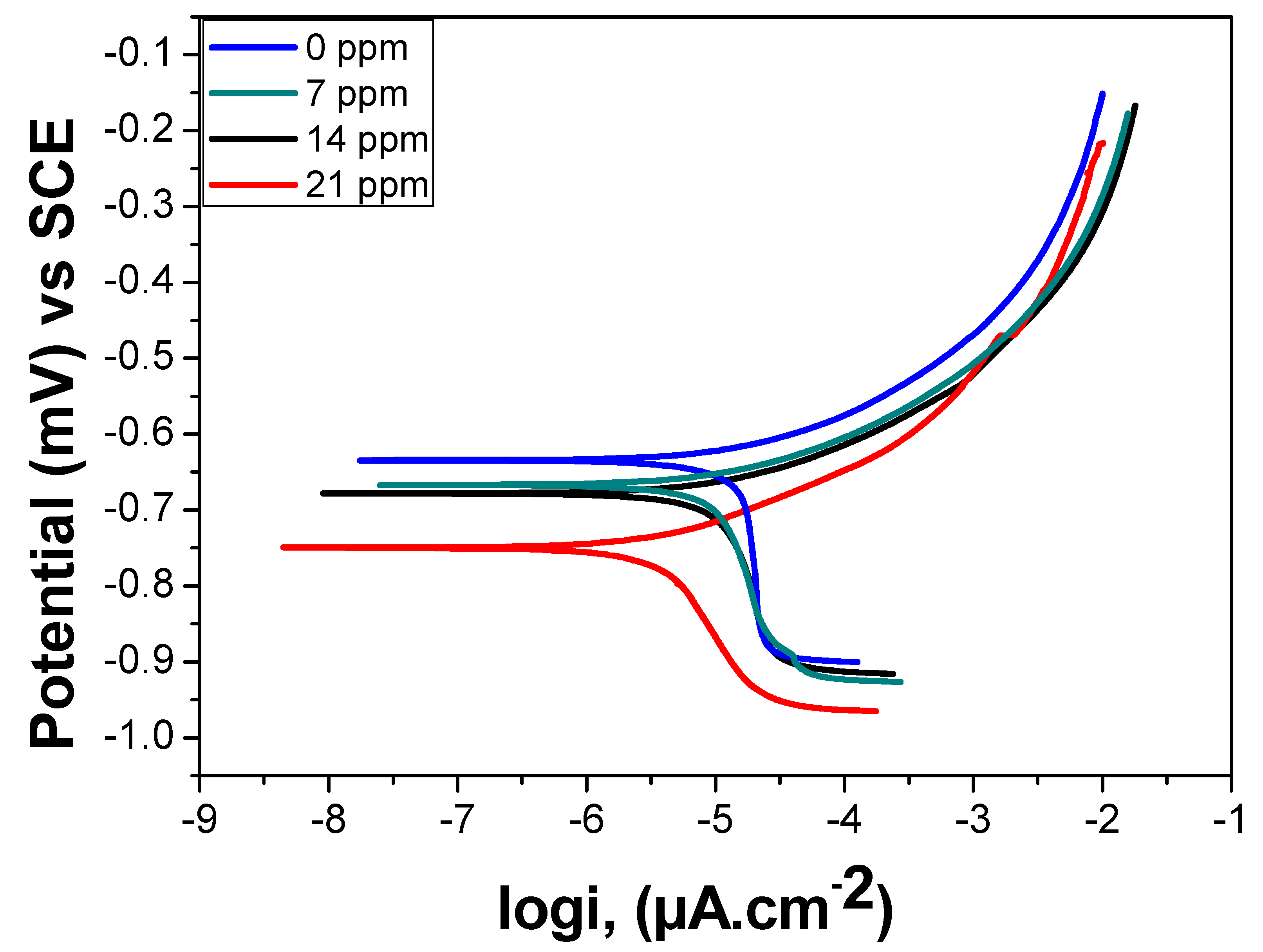
Figure 3 presents the typical potentiodynamic polarization curve of API X100 steels in 3.5% NaCl solution and at different H2S concentrations.
The corrosion current decreases as the anodic current and the potential were scanned from open circuit potential (OCP) in the anodic direction at different H2S bubbling durations, which confirms that the protective nature of the formed sulfide film increases due to the increase in bubbling duration. The decrease in the cathodic current with increasing bubbling duration is attributed to two opposing factors: the pH and the H2S gas concentrations in the solution [10]. Table 2 shows the Tafel parameters derived from the Tafel measurements shown in Figure 3.
3.2. Electrochemical Impedance Spectroscopy (EIS)
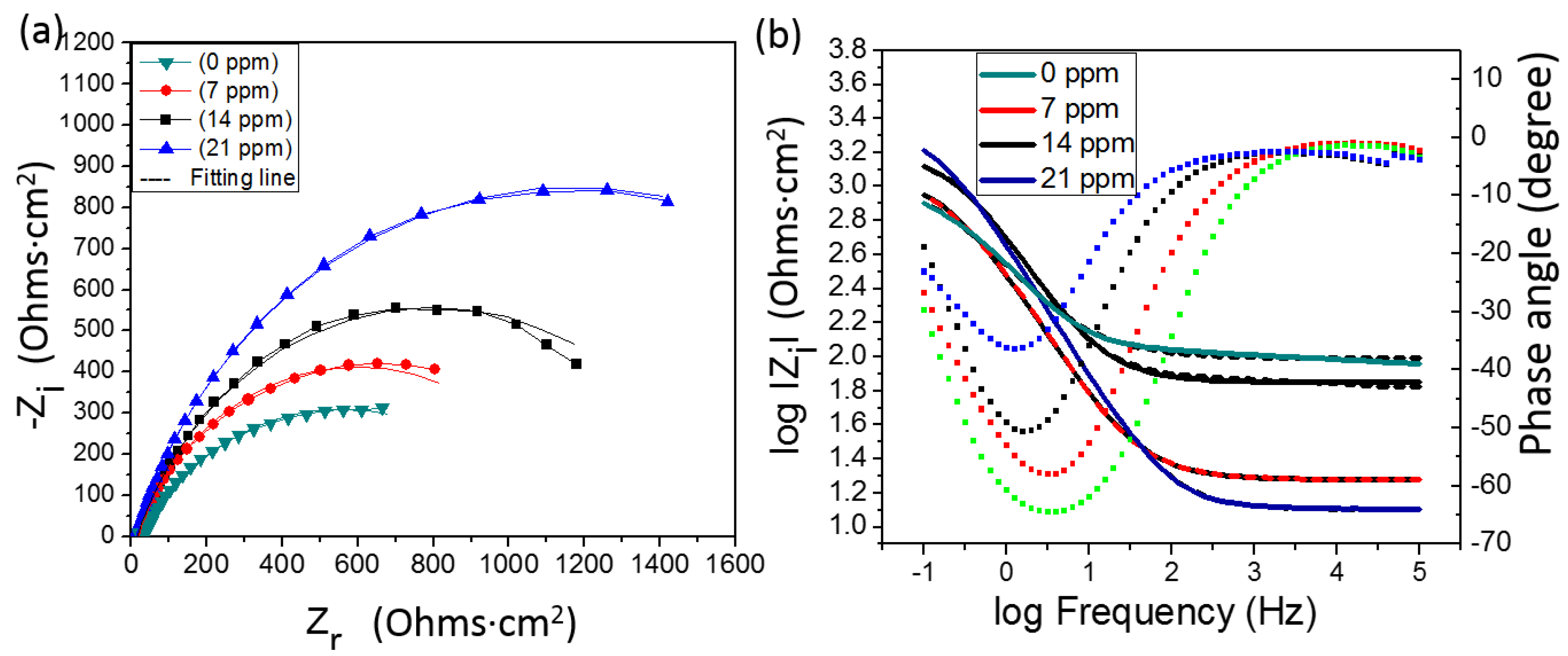
The resistance of carbon steel materials to corrosion depends significantly on the physicochemical properties of the material [31]. Figure 4 shows the measured electrochemical impedance spectra (Nyquist and Bode formats) within a frequency range of 0.1 to 100 KHz starting from the highest to the lowest frequency limit. The corresponding fitted data (dotted line) are also within a frequency range of 0.1 to 100 KHz in 3.5% NaCl solutions saturated with H2S gas at 0, 7, 14, and 21 ppm concentrations. All values were obtained using the Gamry Echem Analysis Software technique [32].
Nyquist and Bode with the phase angle plots obtained for API X100 steel materials tested in 3.5% NaCl solution with and without H2S are shown in Figure 4. An increase in resistance with increasing H2S concentration can be seen in the impedance behavior of the API X100 steel. The Nyquist plot of the API X100 steel without H2S displays a defined single smaller semicircular shape, while the tests with H2S showed increasing semicircular curves (Figure 4). The fitting was done using the equivalent circuit shown in Figure 5. The values of the fitted data are shown in Table 3. In the diagram, Rs represents the solution resistance; CPE in the circuit is the constant phase element; W is the mass transfer Warburg element [33]. Rct stands for the charge transfer resistance, and Rpo is the pore resistance.
It can be observed that an increase in hydrogen sulfide concentration increased the charge transfer resistance (Rct) of the steel [34].
The increase in Rct indicates that the sulfide film is becoming more protective. Additionally, the higher the Rct is, the lower the double layer capacitance will be. As can be seen in Table 3, the most protective sulfide layer was at a hydrogen sulfide concentration of 21 ppm. The corrosion resistance of the API X100 steel increases when the hydrogen sulfide concentration is increased from 0 to 21 ppm. This observation is attributed to the iron sulfide film formation and growth [13,35], which is in good agreement with the findings of Tang et al. [36], who observed similar iron sulfide film deposits on the SAE-1020 carbon steel when exposed to a sour environment. Furthermore, the increase in the hydrogen sulfide concentrations from 14 to 21 ppm showed evidence of crack development, which may be ascribed to hydrogen-induced cracking (HIC). The hydrogen-induced crack (HIC) has been reported to be one of the most significant damage modes in a sour environment [37,38]. It is believed that hydrogen atoms produced due to surface corrosion of the steel diffuse into it through microstructural defects that exist in the material [38]. The accumulation of a critical amount of hydrogen in the metal defeats results in HIC initiation and propagation, as recently reported by Kittel et al. [39].
It is demonstrated that the corrosion resistance of API X100 steel material enhances significantly with increasing sulfide concentration, and can be attributed to the formation of a protective iron sulfide layer on the API X100 steel surface when exposed to an aqueous hydrogen sulfide environment. A previous study [40] has shown that a chemical reaction occurs in a sour environment when H2S is bubbled into the aqueous solution. However, some authors have reported the occurrence of supersaturated mackinawite when low concentrations of H2S are combined with an increase in Fe2+ concentration, resulting in the growth of mackinawite on the steel surface [41,42,43,44]. Furthermore, several authors [45,46] have also reported the significant effects of H2S concentration on the sulfide layer formation.
3.3. Surface Characterizations
The atomic force microscopy (AFM) technique was used for a better understanding of the corroded API X100 steel surface. The 3D AFM images of the corroded surfaces are presented in Figure 6a–d. It is evident that the surface roughness increases with increasing H2S concentration. The specimens corroded at highest H2S concentration have the highest surface roughness (Ra = 400 nm), while the specimens tested in the absence of H2S have the lowest surface roughness (Ra = 50 nm). This behavior can be ascribed to the increase in the formation of more scale layers on the API X100 steel surfaces with increasing concentration of H2S (Figure 6).
Evidence of the sulfide layer formation of sulfide layer on the surface of the API X100 steel specimen when tested in an H2S environment was confirmed by EDX analysis. The presence of sulfur (S) peak in the EDX spectra shown in Figure 7b–d clearly confirms the formation of a sulphide layer on the surface of all API X100 steel tested under H2S environment. However, there was no evidence of “S” in the spectra taken from the test specimen performed without H2S (Figure 7a).
Evidence of cracks can be seen on the sulfide layers at different H2S concentrations, especially at higher concentrations (Figure 7). The phenomenon of the formation of a sulfide film and its cracking is influenced by test solution conditions [47]. It is clear from Figure 7 that deposits of iron sulfide layers have been built up on the sample surface (Figure 7). SEM micrographs shown in Figure 7 reveal that the sulfide layers appear finer and more clustered as the H2S concentration is increased, which can be attributed to the formation of a more homogeneous protective iron sulfide layer on the steel surface. It has been reported that the continuous diffusion of hydrogen sulfide on a steel surface can lead to generate internal stresses into the formed sulfide layer [15]. Upon exceeding the stress limit of the crystalline layer, micro-cracking of the formed layers occurs as observed in Figure 7b–d. Analysis of the corroded metal surface state can be carried out using surface X-ray photoelectron spectroscopy analysis techniques. Figure 8 displays the survey XPS spectra of API X100 steel after exposure to different H2S concentrations. The presence of iron peaks at 709.82 eV, 713.53 eV and a carbon peak at 285.5 eV can be noticed. However, the peaks at 163 and 170 eV binding energy (Figure 8b) indicate the presence of sulfur and thus deduce the possible formation of sulfide layers on the corroded API X100 steel surfaces. This is in good agreement with previous studies [48].
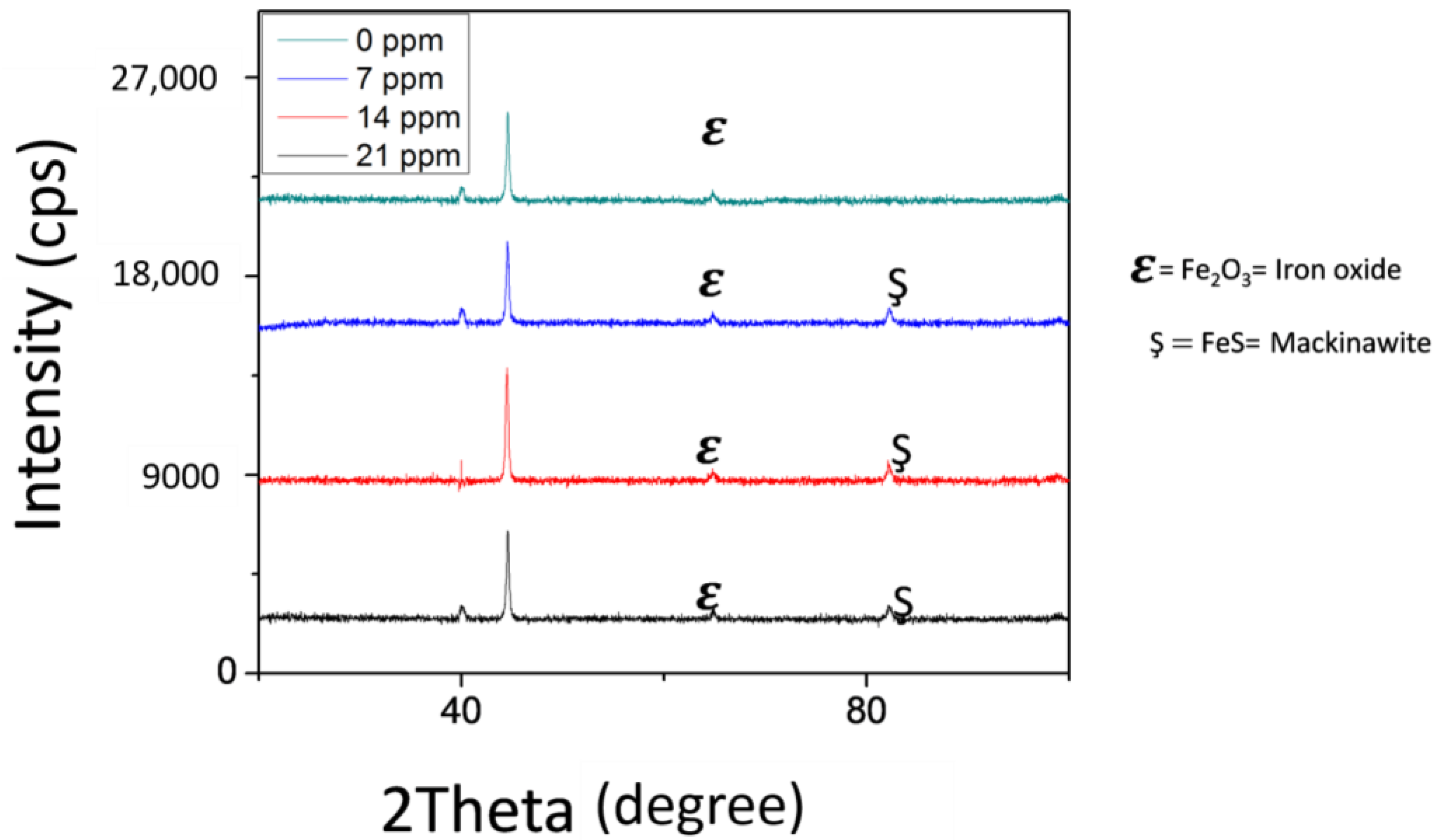
Figure 9 shows the XRD spectra of the corroded API X100 steel samples in saline and sour solutions. XRD peaks located at different 2θ values confirm the presence of different iron compounds. The test performed in the absence of H2S shows a diffraction pattern typical of the peak of iron oxide (Fe2O3, 2θ = 65.08°) [4]. However, the presence of iron sulphide also referred to as mackinawite (FeS, 2θ = 82.43°) was observed on the surface of API X100 steel surface when exposed to different H2S concentrations.
Several researchers have reported that the initial formation of mackinawite layer on the steel surface before the formation of the more stable sulfide species depends on the sample material and the test conditions [49,50]. The presence of this iron sulphide (mackinawite) layer provides some protection to the surface of the material from further corrosion due to its structural orientation [51], resulting in a decrease in the corrosion rate. This protective iron sulfide layer becomes more homogeneous and dense with increasing H2S concentration as can be observed in the SEM micrographs (Figure 7). Similar studies have shown that iron and sulfide films were observed on API X52 pipeline steel surface when exposed to sour environments [4]. However, their quantity is sensitive to the experimental procedure [4,52]. Subsequently, iron sulfide layer (mackinawite) is formed due to the presence of iron and sulfide ions in the solution. Nevertheless, an increase in the sulfide concentration as seen in this test decreases the iron concentration in the solution, resulting in the precipitation of protective iron sulfide on the steel surface [53].
4. Conclusions
In order to understand the effect of hydrogen sulfide on the corrosion behavior of API X100 steel, sets of experiments in the presence and absence of sulfide in 3.5% NaCl were performed on API X100 steel. Based on the experimental results, the following can be concluded:
- EDX and XPS analyses confirm the presence of sulfur on the corroded API X100 steel surfaces at different H2S concentrations.
- A significant decrease in the corrosion rate of API X100 steel in 3.5% NaCl solutions containing various concentrations of H2S is noticed which can be attributed to the formation of sulfide layer.
- SEM micrographs confirm that the formed protective sulfide layer becomes more homogenous and denser as the H2S concentration is increased.
- The formation of more homogeneous, dense and protective iron sulfide layer (mackinawite) is responsible for the decrease in the corrosion rate with increasing concentration of H2S.
Acknowledgments
This publication was made possible by National Priorities Research Program (NPRP) Grant 6-027-2-010 from the Qatar National Research Fund (a member of the Qatar Foundation). Statements made herein are solely the responsibility of the authors.
Author Contributions
Paul C. Okonkwo, Rana Abdul Shakoor, and Adel Mohamed Amer Mohamed conceived and designed the experiments; Paul C. Okonkwo performed the experiments; Rana Abdul Shakoor, Adel Mohamed Amer Mohamed, Abdelbaki Benamor, and Mohammed Jaber F A Al-Marri supervised experimental work and data analysis; Rana Abdul Shakoor and Adel Mohamed Amer Mohamed contributed the analysis tools and reviewed the manuscript; Paul C. Okonkwo wrote the manuscript.
Conflicts of Interest
The authors declare no conflict of interest.
References
- Igi, S.; Sakimoto, T.; Endo, S. Effect of Internal Pressure on Tensile Strain Capacity of X80 Pipeline. Procedia Eng. 2011, 10, 1451–1456. [Google Scholar] [CrossRef]
- Jones, N.; Birch, R.S. Influence of Internal Pressure on the Impact Behavior of Steel Pipelines. J. Press. Vessel. Technol. 1996, 118, 464–471. [Google Scholar] [CrossRef]
- Zhao, M.-C.; Tang, B.; Shan, Y.-Y.; Yang, K. Role of microstructure on sulfide stress cracking of oil and gas pipeline steels. Metall. Mater. Trans. A 2003, 34, 1089–1096. [Google Scholar]
- Hernández-Espejel, A.; Domínguez-Crespo, M.A.; Cabrera-Sierra, R.; Rodríguez-Meneses, C.; Arce-Estrada, E.M. Investigations of corrosion films formed on API-X52 pipeline steel in acid sour media. Corros. Sci. 2010, 52, 2258–2267. [Google Scholar] [CrossRef]
- López, H.F.; Raghunath, R.; Albarran, J.L.; Martinez, L. Microstructural aspects of sulfide stress cracking in an API X-80 pipeline steel. Metall. Mater. Trans. A 1996, 27, 3601–3611. [Google Scholar] [CrossRef]
- Nasirpouri, F.; Mostafaei, A.; Fathyunes, L.; Jafari, R. Assessment of localized corrosion in carbon steel tube-grade AISI 1045 used in output oil–gas separator vessel of desalination unit in oil refinery industry. Eng. Fail. Anal. 2014, 40, 75–88. [Google Scholar] [CrossRef]
- Lens, P.N.L.; Visser, A.; Janssen, A.J.H.; Hulshoff Pol, L.W.; Lettinga, G. Biotechnological Treatment of Sulfate-Rich Wastewaters. Crit. Rev. Environ. Sci. Technol. 1998, 28, 41–88. [Google Scholar] [CrossRef]
- Lucio-Garcia, M.A.; Gonzalez-Rodriguez, J.G.; Casales, M.; Martinez, L.; Chacon-Nava, J.G.; Neri-Flores, M.A.; Martinez-Villafañe, A. Effect of heat treatment on H2S corrosion of a micro-alloyed C–Mn steel. Corros. Sci. 2009, 51, 2380–2386. [Google Scholar] [CrossRef]
- Qi, Y.; Luo, H.; Zheng, S.; Chen, C.; Lv, Z.; Xiong, M. Effect of temperature on the corrosion behavior of carbon steel in hydrogen sulphide environments. Int. J. Electrochem. Sci. 2014, 9, 2101–2112. [Google Scholar]
- Liu, M.; Wang, J.Q.; Ke, W.; Han, E.H. Corrosion Behavior of X52 Anti-H2S Pipeline Steel Exposed to High H2S Concentration Solutions at 90 °C. J. Mater. Sci. Technol. 2014, 30, 504–510. [Google Scholar] [CrossRef]
- Okonkwo, P.C.; Mohamed, A.M.A. Erosion-Corrosion in Oil and Gas Industry: A Review. Int. J. Metall. Mater. Sci. Eng. 2014, 4, 7–28. [Google Scholar]
- Yin, Z.F.; Zhao, W.Z.; Bai, Z.Q.; Feng, Y.R.; Zhou, W.J. Corrosion behavior of SM 80SS tube steel in stimulant solution containing H2S and CO2. Electrochim. Acta 2008, 53, 3690–3700. [Google Scholar] [CrossRef]
- Vedage, H.; Ramanarayanan, T.A.; Mumford, J.D.; Smith, S.N. Electrochemical Growth of Iron Sulfide Films in H2S-Saturated Chloride Media. Corrosion 1993, 49, 114–121. [Google Scholar] [CrossRef]
- Bai, P.; Zheng, S.; Chen, C. Electrochemical characteristics of the early corrosion stages of API X52 steel exposed to H2S environments. Mater. Chem. Phys. 2015, 149–150, 295–301. [Google Scholar] [CrossRef]
- Schulte, M.; Schutze, M. The Role of Scale Stresses in the Sulfidation of Steels. Oxid. Met. 1999, 51, 55–77. [Google Scholar] [CrossRef]
- Carneiro, R.A.; Ratnapuli, R.C.; de Freitas Cunha Lins, V. The influence of chemical composition and microstructure of API linepipe steels on hydrogen-induced cracking and sulfide stress corrosion cracking. Mater. Sci. Eng. A 2003, 357, 104–110. [Google Scholar] [CrossRef]
- Xu, M.; Li, W.; Zhou, Y.; Yang, X.; Wang, Z.; Li, Z. Effect of pressure on corrosion behavior of X60, X65, X70, and X80 carbon steels in water-unsaturated supercritical CO2 environments. Int. J. Greenh. Gas Control. 2016, 51, 357–368. [Google Scholar] [CrossRef]
- Gadala, I.M.; Alfantazi, A. A study of X100 pipeline steel passivation in mildly alkaline bicarbonate solutions using electrochemical impedance spectroscopy under potentiodynamic conditions and Mott–Schottky. Appl. Surf. Sci. 2015, 357, 356–368. [Google Scholar] [CrossRef]
- Eliyan, F.F.; Alfantazi, A. Mechanisms of Corrosion and Electrochemical Significance of Metallurgy and Environment with Corrosion of Iron and Steel in Bicarbonate and Carbonate Solutions—A Review. Corrosion 2014, 70, 880–898. [Google Scholar] [CrossRef]
- Sherar, B.W.A.; Keech, P.G.; Noël, J.J.; Worthingham, R.G.; Shoesmith, D.W. Effect of Sulfide on Carbon Steel Corrosion in Anaerobic Near-Neutral pH Saline Solutions. Corrosion 2012, 69, 67–76. [Google Scholar] [CrossRef]
- Papavinasam, S.; Doiron, A.; Revie, R.W. Model to Predict Internal Pitting Corrosion of Oil and Gas Pipelines. Corrosion 2010, 66. [Google Scholar] [CrossRef]
- Sridhar, N.; Dunn, D.S.; Anderko, A.M.; Lencka, M.M.; Schutt, H.U. Effects of Water and Gas Compositions on the Internal Corrosion of Gas Pipelines—Modeling and Experimental Studies. Corrosion 2001, 57, 221–235. [Google Scholar] [CrossRef]
- Han, J.; Carey, J.W.; Zhang, J. Effect of sodium chloride on corrosion of mild steel in CO2-saturated brines. J. Appl. Electrochem. 2011, 41, 741–749. [Google Scholar] [CrossRef]
- Shi, J.; Sun, W.; Jiang, J.; Zhang, Y. Influence of chloride concentration and pre-passivation on the pitting corrosion resistance of low-alloy reinforcing steel in simulated concrete pore solution. Constr. Build. Mater. 2016, 111, 805–813. [Google Scholar] [CrossRef]
- Abayarathna, D.; Naraghi, A.R.; Wang, S.H. The Effect of Surface Films on Corrosion of Carbon Steel in a CO2–H2S–H2O System in Corrosion/2005; NACE: Houston, TX, USA, 2005. [Google Scholar]
- Valcarce, M.B.; Vázquez, M. Carbon steel passivity examined in alkaline solutions: The effect of chloride and nitrite ions. Electrochim. Acta 2008, 53, 5007–5015. [Google Scholar] [CrossRef]
- Rao, T.S.; Sairam, T.N.; Viswanathan, B.; Nair, K.V.K. Carbon steel corrosion by iron oxidising and sulphate reducing bacteria in a freshwater cooling system. Corros. Sci. 2000, 42, 1417–1431. [Google Scholar] [CrossRef]
- Paul, C.O.; Ahmed, E.; Mohamed, A.M.A. Effect of Temperature on the Corrosion Behavior of API X80 Steel Pipeline. Int. J. Electrochem. Sci. 2015, 10, 10246–10260. [Google Scholar]
- Okonkwo, P.; Shakoor, R.; Zagho, M.; Mohamed, A. Erosion Behaviour of API X100 Pipeline Steel at Various Impact Angles and Particle Speeds. Metals 2016, 6, 232. [Google Scholar] [CrossRef]
- TM0284–2003, N.S. Evaluation of Pipeline and Pressure Vessel Steels for Resistance to Hydrogen-induced Cracking; NACE International: Houston, TX, USA, 2003. [Google Scholar]
- Saravanamoorthy, S.; Velmathi, S. Physiochemical interactions of chiral Schiff bases on high carbon steel surface: Corrosion inhibition in acidic media. Prog. Org. Coat. 2013, 76, 1527–1535. [Google Scholar] [CrossRef]
- Musa, A.Y.; Kadhum, A.A.H.; Mohamad, A.B.; Rahoma, A.A.B.; Mesmari, H. Electrochemical and quantum chemical calculations on 4,4-dimethyloxazolidine-2-thione as inhibitor for mild steel corrosion in hydrochloric acid. J. Mol. Struct. 2010, 969, 233–237. [Google Scholar] [CrossRef]
- Liu, H.J.; Xu, Q.; Yan, C.W.; Cao, Y.Z.; Qiao, Y.L. The Effect of Temperature on the Electrochemical Behavior of the V(IV)/V(V) Couple on a Graphite Electrode. Int. J. Electrochem. Sci. 2011, 6, 3483–3496. [Google Scholar]
- Islam, M.A.; Farhat, Z.N. Characterization of the Corrosion Layer on Pipeline Steel in Sweet Environment. J. Mater. Eng. Perform. 2015, 24, 3142–3158. [Google Scholar] [CrossRef]
- Huang, H.-H.; Tsai, W.-T.; Lee, J.-T. Electrochemical behavior of the simulated heat-affected zone of A516 carbon steel in H2S solution. Electrochim. Acta 1996, 41, 1191–1199. [Google Scholar] [CrossRef]
- Tang, J.; Shao, Y.; Guo, J.; Zhang, T.; Meng, G.; Wang, F. The effect of H2S concentration on the corrosion behavior of carbon steel at 90 °C. Corros. Sci. 2010, 52, 2050–2058. [Google Scholar] [CrossRef]
- Elboujdaini, M.; Revie, R.W. Metallurgical factors in stress corrosion cracking (SCC) and hydrogen-induced cracking (HIC). J. Solid State Electrochem. 2009, 13, 1091–1099. [Google Scholar] [CrossRef]
- Lu, B.T.; Luo, J.L. Relationship between Yield Strength and Near-Neutral pH Stress Corrosion Cracking Resistance of Pipeline Steels—An Effect of Microstructure. Corrosion 2006, 62, 129–140. [Google Scholar] [CrossRef]
- Kittel, J.; Smanio, V.; Fregonese, M.; Garnier, L.; Lefebvre, X. Hydrogen-induced cracking (HIC) testing of low alloy steel in sour environment: Impact of time of exposure on the extent of damage. Corros. Sci. 2010, 52, 1386–1392. [Google Scholar] [CrossRef]
- Ma, H.; Cheng, X.; Li, G.; Chen, S.; Quan, Z.; Zhao, S.; Niu, L. The influence of hydrogen sulfide on corrosion of iron under different conditions. Corros. Sci. 2000, 42, 1669–1683. [Google Scholar] [CrossRef]
- Buckley, A.N.; Woods, R. The surface oxidation of pyrite. Appl. Surf. Sci. 1987, 27, 437–452. [Google Scholar] [CrossRef]
- Hamilton, I.C.; Woods, R. An investigation of surface oxidation of pyrite and pyrrhotite by linear potential sweep voltammetry. J. Electroanal. Chem. Interfacial Electrochem. 1981, 118, 327–343. [Google Scholar] [CrossRef]
- King, R.A.; Miller, J.D.A.; Smith, J.S. Corrosion of Mild Steel by Iron Sulphides. Br. Corros. J. 1973, 8, 137–141. [Google Scholar]
- Lee, W.; Lewandowski, Z.; Nielsen, P.H.; Hamilton, W.A. Role of sulfate-reducing bacteria in corrosion of mild steel: A review. Biofouling 1995, 8, 165–194. [Google Scholar] [CrossRef]
- Choi, Y.-S.; Nesic, S.; Ling, S. Effect of H2S on the CO2 corrosion of carbon steel in acidic solutions. Electrochimica Acta 2011, 56, 1752–1760. [Google Scholar] [CrossRef]
- Sardisco, J.B.; Pitts, R.E. Corrosion of Iron in an H2S-CO2-H2O System Mechanism of Sulfide Film Formation and Kinetics of Corrosion Reaction. Corrosion 1965, 21, 245–253. [Google Scholar] [CrossRef]
- Bonis, M.; Crolet, J.-L. Practical aspects of the influence of in situ pH on H2S-induced cracking. Corros. Sci. 1987, 27, 1059–1070. [Google Scholar] [CrossRef]
- Heuer, J.K.; Stubbins, J.F. An XPS characterization of FeCO3 films from CO2 corrosion. Corros. Sci. 1999, 41, 1231–1243. [Google Scholar] [CrossRef]
- Rickard, D. Metastable Sedimentary Iron Sulfides. Dev. Sedimentol. 2012, 65, 195–231. [Google Scholar]
- Bai, P.; Zheng, S.; Chen, C.; Zhao, H. Investigation of the iron-sulfide phase transformation in nanoscale. Cryst. Growth Des. 2014, 14, 4295–4302. [Google Scholar] [CrossRef]
- Solehudin, A.; Nurdin, I.; Suratno, W.; Agma, M. EIS Study of Temperature and H2S Concentration Effect on API 5LX65 Carbon Steel Corrosion in Chloride Solution. J. Mater. Sci. Eng. A 2011, 1, 496–505. [Google Scholar]
- Lowson, R.T. Aqueous oxidation of pyrite by molecular oxygen. Chem. Rev. 1982, 82, 461–497. [Google Scholar] [CrossRef]
- El Mendili, Y.; Abdelouas, A.; Bardeau, J.F. Impact of a sulphidogenic environment on the corrosion behavior of carbon steel at 90 °C. RSC Adv. 2013, 3, 15148–15156. [Google Scholar] [CrossRef]
Figure 1.
Scanning electron microscopy (SEM) micrograph of API X100 steel.
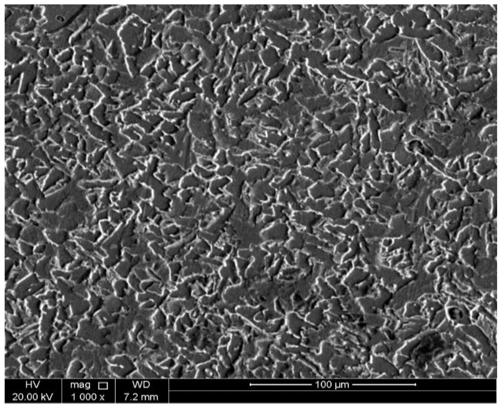
Figure 2.
Schematic diagram of the corrosion test set-up employed to study the corrosion behavior of API X100 steel at room temperature.
Figure 2.
Schematic diagram of the corrosion test set-up employed to study the corrosion behavior of API X100 steel at room temperature.
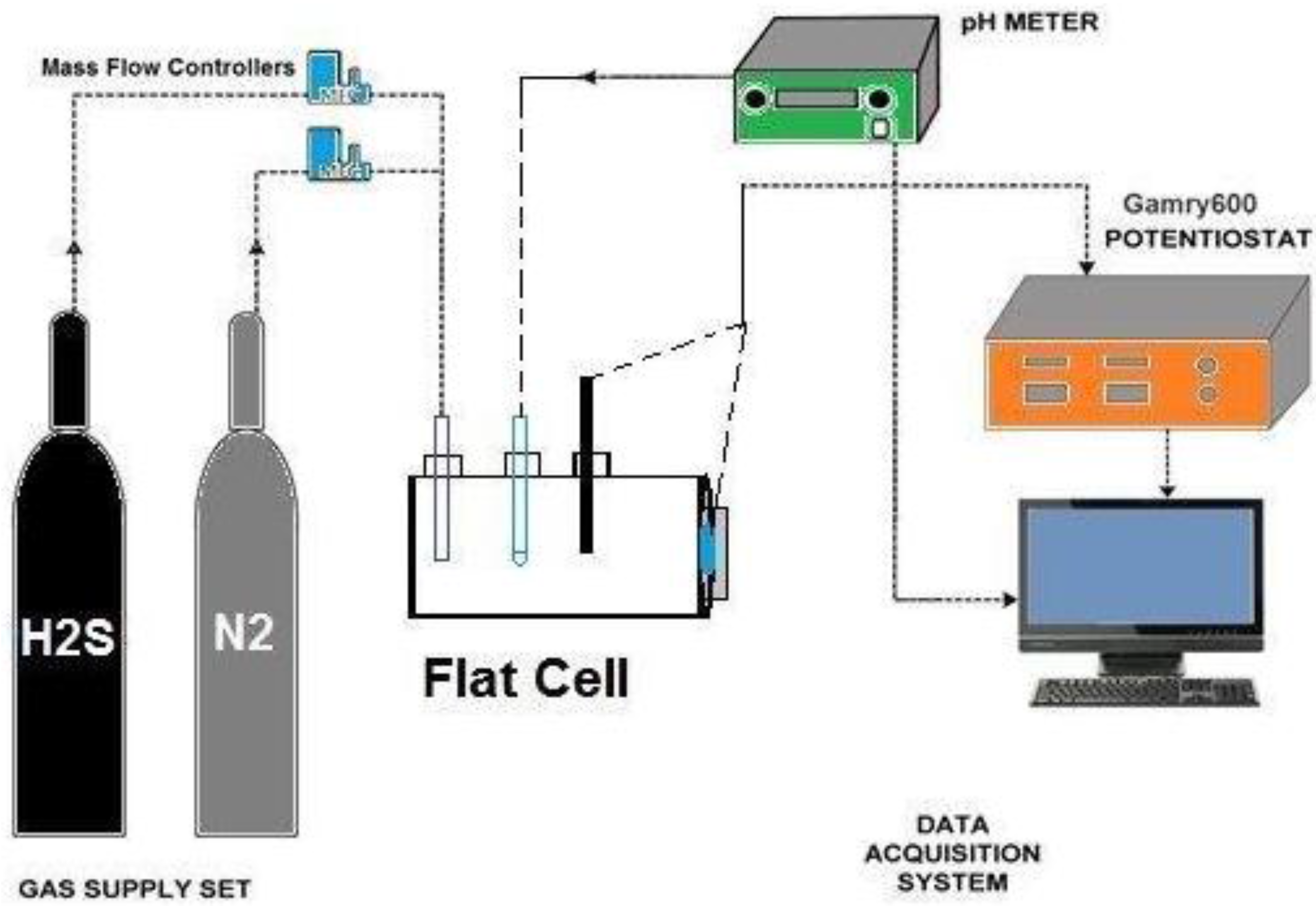
Figure 3.
Potentiodynamic polarization curves of API X100 steels.

Figure 4.
Measured Electrochemical Impedance Spectroscopy (EIS) data represented in (a) Nyquist and (b) Bode with phase angle represented in a dotted line format for API X100 steel at different durations in 3.5% NaCl solutions with hydrogen sulfide within a frequency range of 0.1 to 100 KHz.
Figure 4.
Measured Electrochemical Impedance Spectroscopy (EIS) data represented in (a) Nyquist and (b) Bode with phase angle represented in a dotted line format for API X100 steel at different durations in 3.5% NaCl solutions with hydrogen sulfide within a frequency range of 0.1 to 100 KHz.

Figure 5.
The equivalent electrical circuit model used to analysis the EIS data. CPE: constant phase element.
Figure 5.
The equivalent electrical circuit model used to analysis the EIS data. CPE: constant phase element.
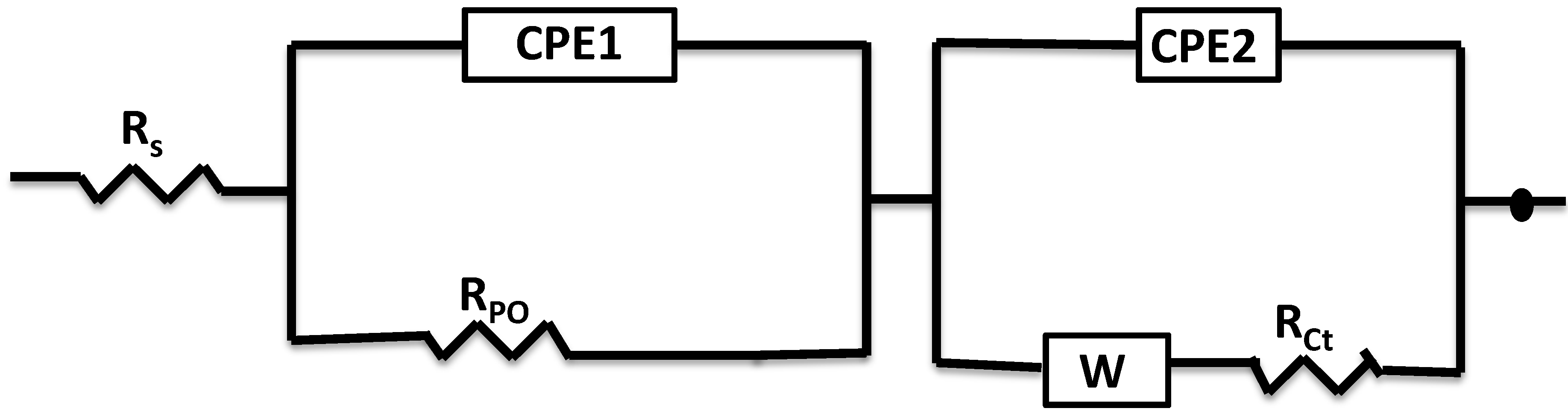
Figure 6.
3D atomic force microscopy (AFM) images of API X100 steel exposed to a sour environment at different H2S concentrations of (a) 0 ppm; (b) 7 ppm; (c) 14 ppm; (d) 21 ppm.
Figure 6.
3D atomic force microscopy (AFM) images of API X100 steel exposed to a sour environment at different H2S concentrations of (a) 0 ppm; (b) 7 ppm; (c) 14 ppm; (d) 21 ppm.
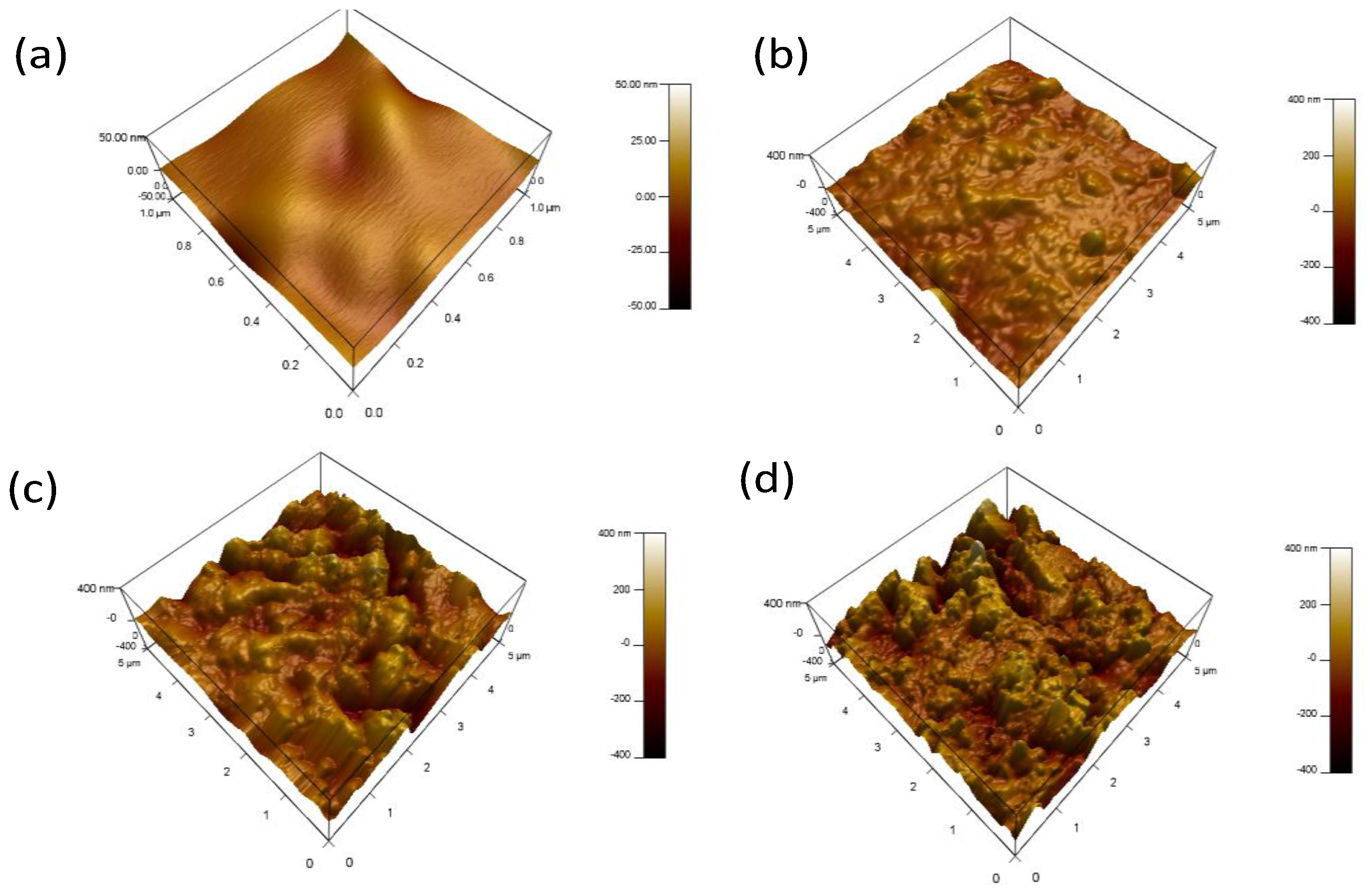
Figure 7.
SEM images of API X100 steel material for tests conducted in 3.5% NaCl (a) without H2S, (b) with 7 ppm of H2S, (c) with 14 ppm H2S, and (d) with 21 ppm H2S.
Figure 7.
SEM images of API X100 steel material for tests conducted in 3.5% NaCl (a) without H2S, (b) with 7 ppm of H2S, (c) with 14 ppm H2S, and (d) with 21 ppm H2S.
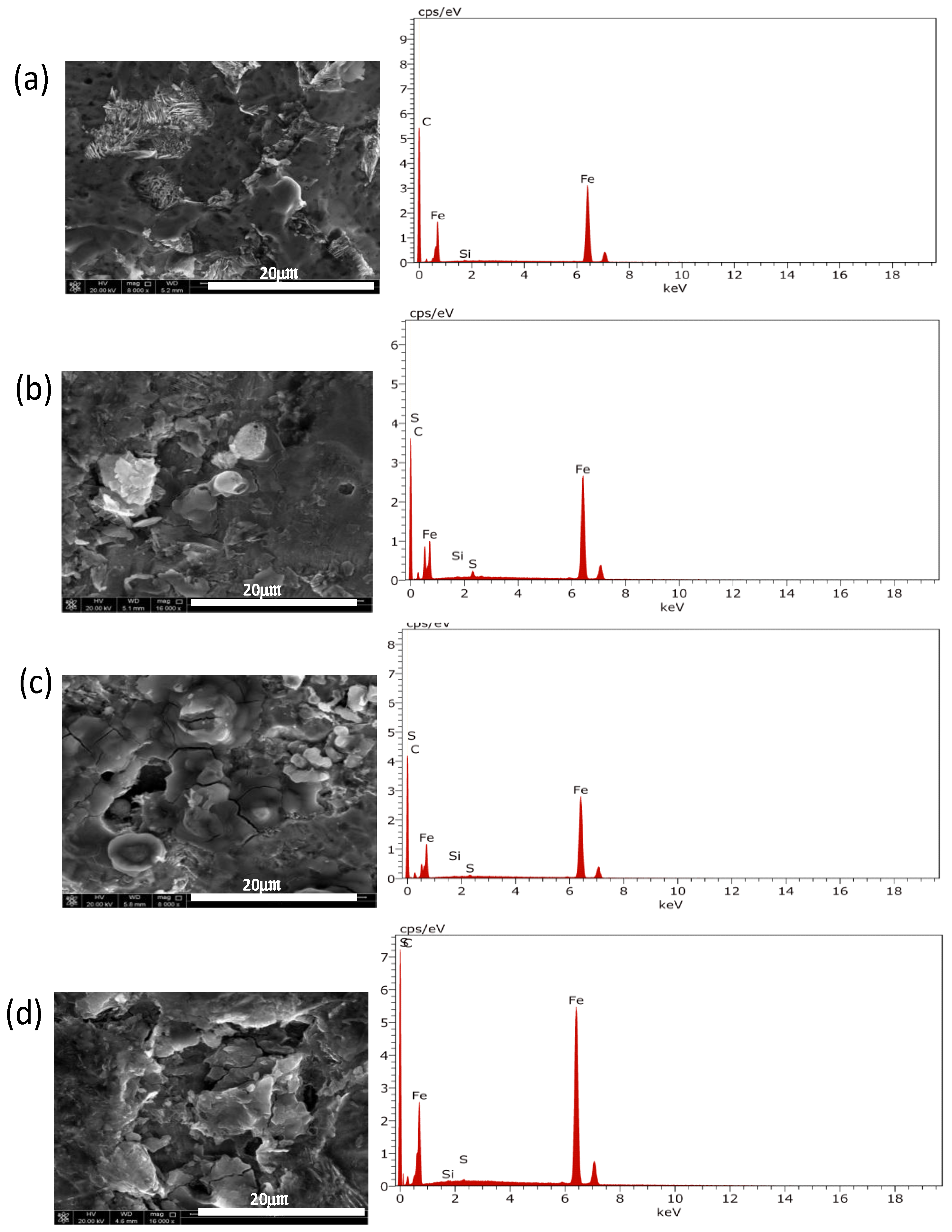
Figure 8.
X-ray photoelectron spectroscopy (XPS) fitting spectra obtained from (a) the survey and (b) the sulfur spectra with a fitted line of corroded API X100 steel at 21 ppm of H2S.
Figure 8.
X-ray photoelectron spectroscopy (XPS) fitting spectra obtained from (a) the survey and (b) the sulfur spectra with a fitted line of corroded API X100 steel at 21 ppm of H2S.
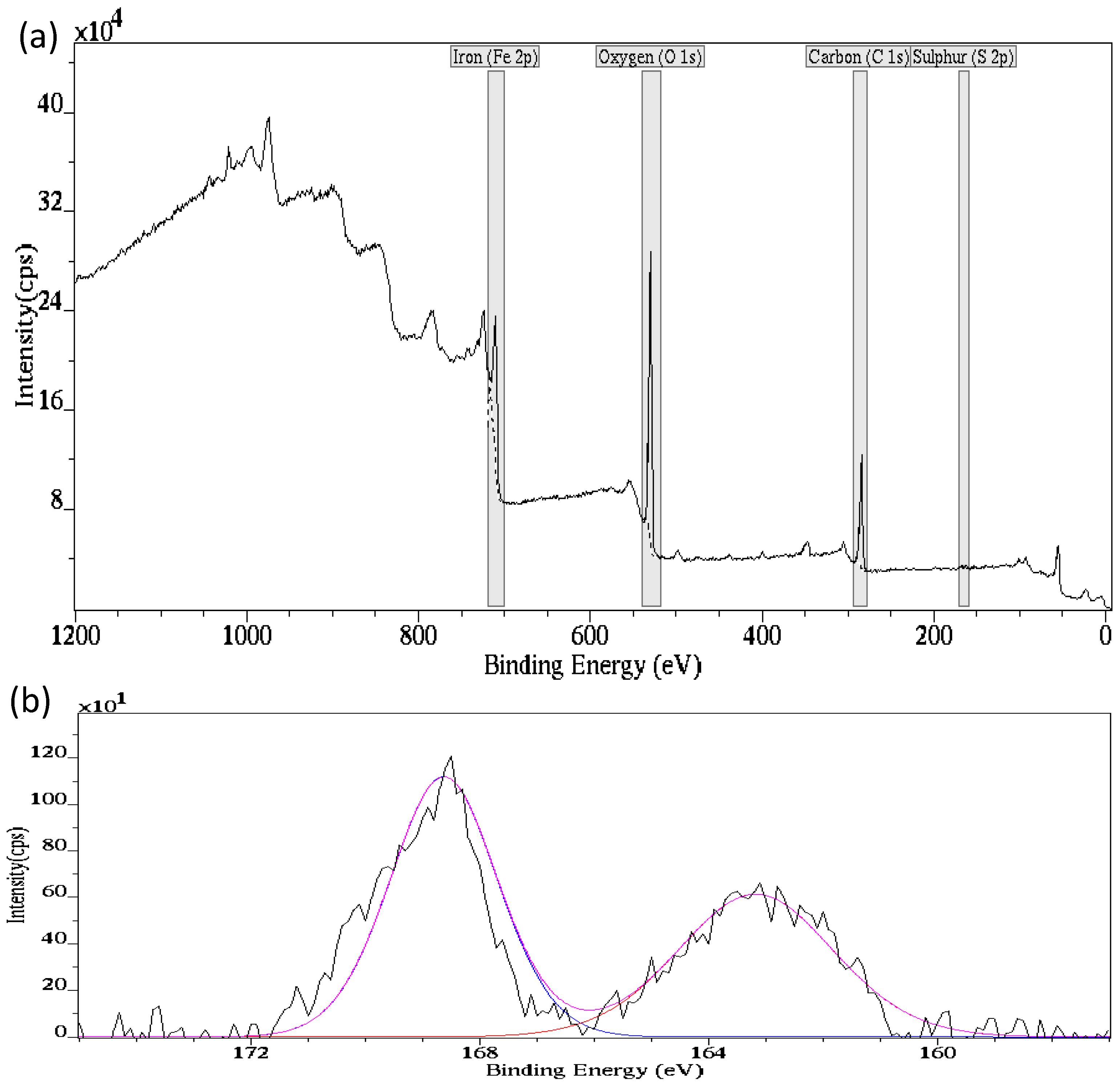
Figure 9.
The XRD spectra of API X100 with the corrosion product films at different H2S concentrations. Scanning was at 2°S−1.
Figure 9.
The XRD spectra of API X100 with the corrosion product films at different H2S concentrations. Scanning was at 2°S−1.

Table 1.
The pH and H2S concentration used in the tests.
| H2S Gas Bubbling Duration (h) | H2S Concentration (ppm) | PH |
|---|---|---|
| 0 | 0 | 7.13 |
| 1 | 7 | 6.58 |
| 3 | 14 | 6.02 |
| 6 | 21 | 4.91 |
Table 2.
The Tafel analysis parameters derived from the Tafel measurement shown in Figure 3.
Table 2.
The Tafel analysis parameters derived from the Tafel measurement shown in Figure 3.
| H2S Concentration (ppm) | Ecorr (V) | Icorr (µA·cm−2) | βc (V·decade−1) | βa (V·decade−1) × 10−3 |
|---|---|---|---|---|
| 0 | −0.633 ± 0.011 | 52.29 ± 0.091 | 1.011 ± 0.012 | 98.92 ± 0.007 |
| 7 | −0.667 ± 0.020 | 28.52 ± 0.054 | 1.018 ± 0.013 | 112.1 ± 0.013 |
| 14 | −0.679 ± 0.015 | 22.15 ± 0.013 | 1.012 ± 0.006 | 116.7 ± 0.008 |
| 21 | −0.748 ± 0.012 | 6.89 ± 0.017 | 535.8 ± 0.014 | 103.8 ± 0.015 |
Table 3.
Influence of hydrogen sulfide concentration on the corrosion of API X100 steel—data exported from fitted circuits.
Table 3.
Influence of hydrogen sulfide concentration on the corrosion of API X100 steel—data exported from fitted circuits.
| H2S Concentration (ppm) | Rs (ohm·cm2) | Rpo (ohm·cm2) | CPE1 (Ssncm−2) × 10−3 | n1 | Rct (ohm·cm2) | CPE2 (Ssncm−2) × 10−4 | n2 |
|---|---|---|---|---|---|---|---|
| 0 | 12.73 | 52.95 | 4.52 | 0.735 | 840 | 5.17 | 0.869 |
| 7 | 19.05 | 67.13 | 3.31 | 0.718 | 1095 | 4.82 | 0.785 |
| 14 | 70.99 | 98.22 | 2.78 | 0.632 | 1440 | 3.09 | 0.807 |
| 21 | 98.19 | 106.10 | 1.52 | 0.640 | 1747 | 2.17 | 0.676 |
© 2017 by the authors. Licensee MDPI, Basel, Switzerland. This article is an open access article distributed under the terms and conditions of the Creative Commons Attribution (CC BY) license (http://creativecommons.org/licenses/by/4.0/).
Share and Cite
MDPI and ACS Style
Okonkwo, P.C.; Shakoor, R.A.; Benamor, A.; Amer Mohamed, A.M.; Al-Marri, M.J.F.A. Corrosion Behavior of API X100 Steel Material in a Hydrogen Sulfide Environment. Metals 2017, 7, 109. https://doi.org/10.3390/met7040109
AMA Style
Okonkwo PC, Shakoor RA, Benamor A, Amer Mohamed AM, Al-Marri MJFA. Corrosion Behavior of API X100 Steel Material in a Hydrogen Sulfide Environment. Metals. 2017; 7(4):109. https://doi.org/10.3390/met7040109
Chicago/Turabian StyleOkonkwo, Paul C., Rana Abdul Shakoor, Abdelbaki Benamor, Adel Mohamed Amer Mohamed, and Mohammed Jaber F A Al-Marri. 2017. "Corrosion Behavior of API X100 Steel Material in a Hydrogen Sulfide Environment" Metals 7, no. 4: 109. https://doi.org/10.3390/met7040109
Note that from the first issue of 2016, this journal uses article numbers instead of page numbers. See further details here.