Heating System for Riser Size Minimizing in Sand Casting Process and Its Experimental Verification


1
School of Mechanical Engineering, Kyungnam University, 7 Kyungnamdaehak-ro, Masanhappo-gu, Changwon-si, Gyeongsangnam-do, 51767, Korea
2
Global Core Research Center for Ship and Offshore Plants (GCRE-SOP), San 30 Chang Jun-dong, Geum Jung-Gu, Busan 46241, Korea
3
School of Mechanical Engineering, Pusan National University, San 30 Chang Jun-dong, Geum Jung-Gu, Busan 46241, Korea
*
Author to whom correspondence should be addressed.
Metals 2017, 7(4), 130; https://doi.org/10.3390/met7040130
Submission received: 28 February 2017
/
Revised: 26 March 2017
/
Accepted: 4 April 2017
/
Published: 8 April 2017
Abstract
:In the conventional sand casting process, the size of the riser is made larger than that of the cavity (product part) in order for the molten metal in the riser to solidify at a later stage than the molten metal in the cavity. In this study, a continuous heating method is developed and applied to the riser, using a cylindrical heater, to minimize the size of the riser. A mold having four cavities is designed for casting turbine housings. The height and diameter of the riser are chosen to be 80 mm and 20 mm, respectively. Solidification analysis results, using the analysis program MAGMA soft for casting simulation, showed that when the heater is implemented, the riser is the last to solidify. However, without the heater, the riser solidifies before the cavity, thus causing the riser to function improperly. Moreover, misruns are generated in the casted product if the heater is not implemented, as opposed to the case of a solid product without any defects, with the heater attached in the riser.
1. Introduction
Generally, the sand casting process comprises a gating system that sends molten metal into the mold cavity wherein the molten metal is converted into a solid product. Molten metal is poured into the mold through the gate system and flows through the cavity, finally reaching the riser. Once it is confirmed that molten metal has reached the riser, the pouring of the molten metal is stopped. Owing to the riser being positioned higher than the cavity, its potential energy is higher than that of the molten metal in the cavity. With this arrangement, the molten metal inside the riser compensates for volume reduction due to shrinkage during the solidification of the molten metal when it is solidified inside the mold. Therefore, the molten metal inside the riser must be solidified at a later stage than the molten metal inside the cavity. If the size of the riser is adequately designed, the shrinkage cavity that is generated inside the mold is reduced, and a dense structure can be obtained in the casting product, which produces a high quality casting. However, if the size of the riser is not correctly designed (the riser is too large), productivity is affected because of high material costs, low recovery rate, longer solidification time, and long post-processing for the removal of the riser. On the other hand, if the size of the riser is too small, a defective casting is produced. As casting defects are the biggest issues occurring in the process, casting companies use risers larger than the product size for the casting process [1,2,3,4].
Moreover, because the objective of the sand cast is to reduce the defects of the casting products as much as possible, there is no special idea concerning the design of the riser. The present situation is that the workers at the site select the volume of the riser according to the dimensions of the cavity. They also select the location of the riser by detecting the point where freeze shrinkage would occur [5,6].
Furthermore, the volume of the riser is made large so that the molten metal located inside the riser can solidify at a later stage than the molten metal inside the cavity. Moreover, riser insulation is used to reduce the heat transfer rate. In this study, a cylindrical heating method is suggested instead of a riser insulation method to reduce the volume of the riser [2,5,6,7].
The casting parts used in this study are the turbine housings in turbocharger systems. The turbocharger is powered by a turbine driven by the engine’s exhaust gas. The turbocharger system consists of a turbine and a compressor. Turbocharger systems are used to improve the efficiency of internal combustion engines in automobiles. This improvement over a naturally aspirated engine’s power output is due to the fact that the compressor can force more air and proportionately more fuel into the combustion chamber than atmospheric pressure alone [8,9]. The temperature of the exhaust gas in a diesel engine is around 800–900 °C. Consequently, if the housing cannot withstand such a high temperature, not only is the turbocharger damaged, but also the entire engine as well. Therefore, turbine housings of diesel engines are being manufactured with spheroidal graphite (GCD) cast iron, since it offers better properties at high temperature than other families of cast alloys [10]. Turbine housing is considerably complicated and extremely difficult to manufacture with machining or metal forming processes. Consequently, it is manufactured using the sand casting process [10,11]. However, the turbine housing is a thin-walled product with a tube thickness lesser than 10 mm. This difficulty of shape leads to the generation of many defects, thus adding challenges to its manufacturing process [10,11,12,13,14]. The housings of the compressor are normally manufactured by using titling casting of aluminum.
This study focuses on the improvement of the recovery rate by minimizing the size of the riser, using a cylindrical heater, for the casting of the turbine housing. The size of the riser was then altered accordingly, and test results with and without the heater, on risers having the same size, were compared. The gate system for the casting of the turbine housing was designed using two models, and these models were verified through casting analysis, using the casting analysis program, MAGMA. Analyses were performed for observing the flow behavior of the molten metal in the mold and solidification of the molten metal. A tensile test, Brinell hardness test, impact test, and X-ray inspection were performed as part of the analysis of physical properties, for the casted product. The microstructure of the casting was also examined.
2. Methods Simulation and Experimental
2.1. Design of the Product and Mold
Figure 1 shows a drawing of the designed turbine housing. It has the shape of a cochlea with a height of 110 mm, width of 130 mm, and a thickness of 54 mm. The turbine housing has a tube shape with a hollow inner part where the wheel is installed. Therefore, the thinnest portion of the tube is 6.2 mm thick. The volume of the turbine housing is 218,896 mm3 and its mass is 1.72 kg.
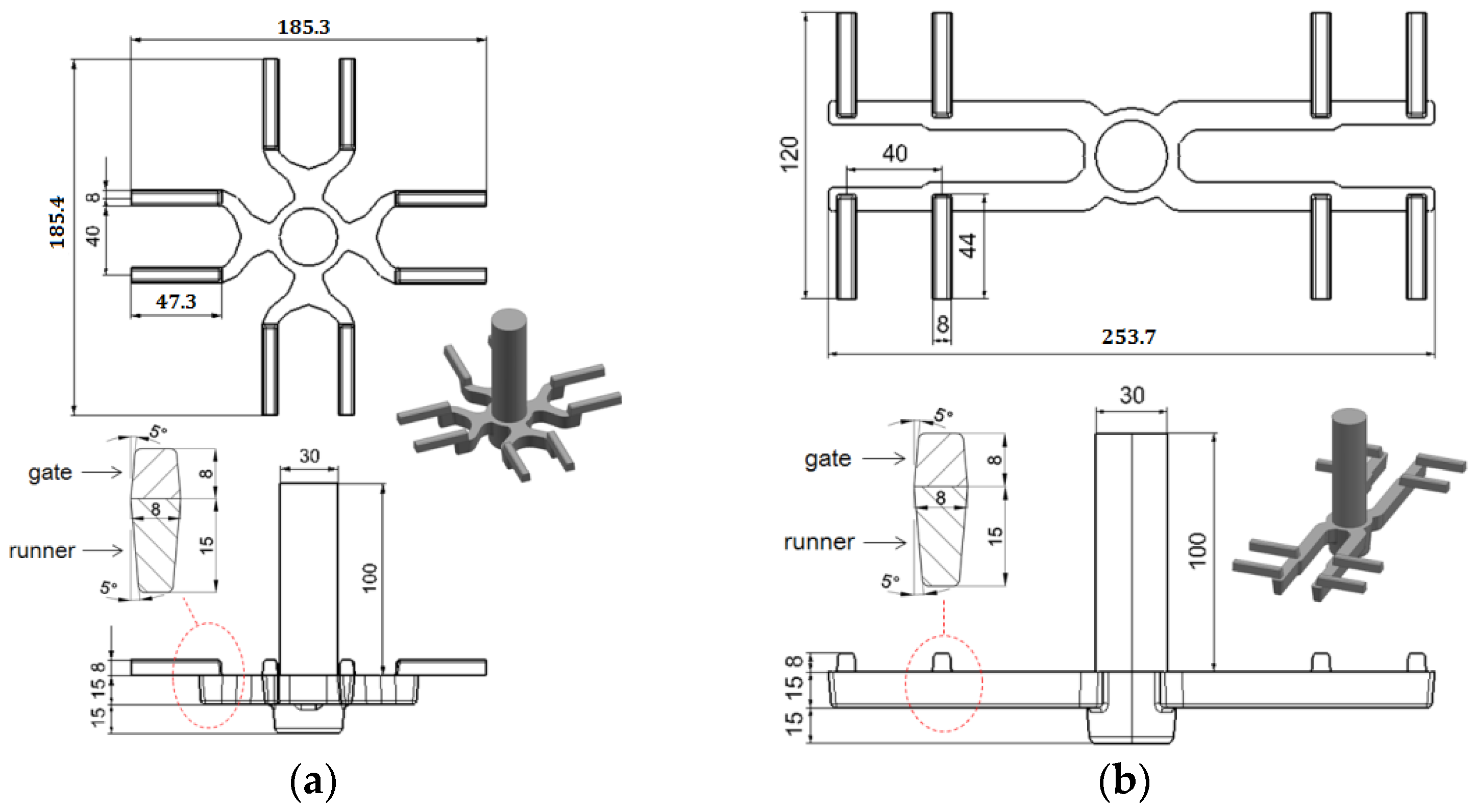
Figure 2 shows a drawing of the gate system. The gate system was designed using two models. The filling analysis results for the molten metal that is filled into the mold was conducted using MAGMA (V5, MAGMA, Aachen, Germany, 1988) and analysis results for both models were compared. The model has four turbine housings attached to the gate system; therefore, when molten metal is filled once, four turbine housings are produced. There are eight gates and two gates are connected to one turbine housing. The diameter and height of the sprue is 30 mm and 100 mm, respectively. The thickness and width of the runner is 15 mm and 8 mm, respectively and the thickness and width of the gate is both 8 mm for each gate. Therefore, SRG ratio (Sprue:Runner:Gate) is 1:1.2:0.65. Figure 2a shows a model wherein the runner and gate are arranged as a +shape and the mass of the gate system is 1.28 kg. Figure 2b shows a model wherein the gate is arranged as the number 11 and the gate is bent at a 90° angle from the runner. The mass of the gate system is 1.51 kg.
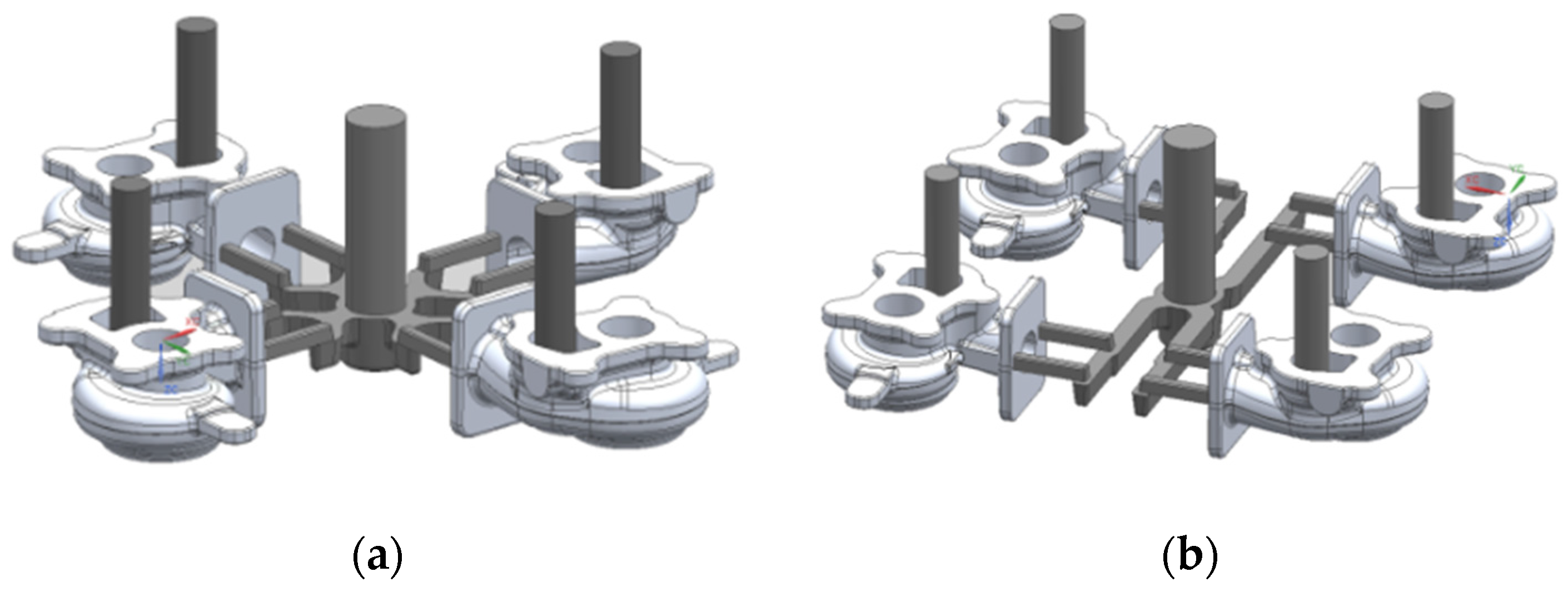
Figure 3 shows the shape of the inside of the mold. The turbine housing is attached to the gate system and the riser is attached onto the turbine housing. As the riser is connected to each turbine housing, there are totally four risers. The height of each riser is 80 mm. The diameters of the risers were designed to be 20 mm and 10 mm and their performances were compared using analyses and experiments. The mass of the riser having a diameter of 20 mm is 0.21 kg; thus, the combined mass of the first four risers is 0.84 kg. Moreover, the mass of the riser having a 10 mm diameter is 0.0525 kg, which makes the combined mass of the other four risers 0.21 kg.
When the riser having a 10 mm diameter is attached as shown in the casting model in Figure 3a, the recovery rate is 77%. However, if the riser having a 20 mm diameter is attached using the same casting model, the recovery rate is 82%. Moreover, if the riser having a 10 mm diameter is attached as in the casting model in Figure 3b, the recovery rate is 75%. If the riser having a 20 mm diameter is attached using the same casting model, the recovery rate is 80%. These values are reported in Table 1. Furthermore, because the mass of the gate system in the casting model in Figure 3a is 0.23 kg lighter than that of the model in Figure 3b, the recovery rate is higher by approximately 2%. The recovery rate was calculated using Equation (1).
where is the weight of the product and is weight of the gate system and riser.
2.2. Conditions of Simulation
The initial temperature and the boundary conditions used in the finite elements analysis were set as close as possible to the experimental conditions [15]. The raw material was cast iron 500 (GCD 500), and the pouring temperature for the molten metal was set at 1400 °C. Table 2 shows the chemical compositions of GCD 500 [15]. Table 3 shows the condition of sand casting simulation of MAGMA soft. The temperature of the mold (sand) was set at 20 °C. The heat transfer coefficient between casting and sand mold by the temperature difference method. The medium value is about 300 W/m2K. A cylindrical heater was modeled to provide a constant temperature to the riser and attached on the riser as shown in Figure 4. The temperature of the cylindrical heater was set at 650 °C. Analysis was then carried out for the case of the riser being heated using the cylindrical heater as well as the case using the insulation material.
2.3. Conditions of Experiment
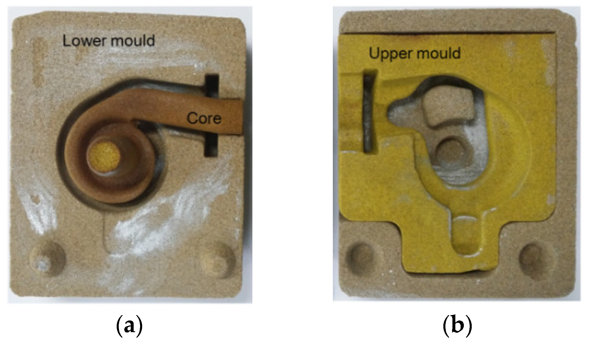
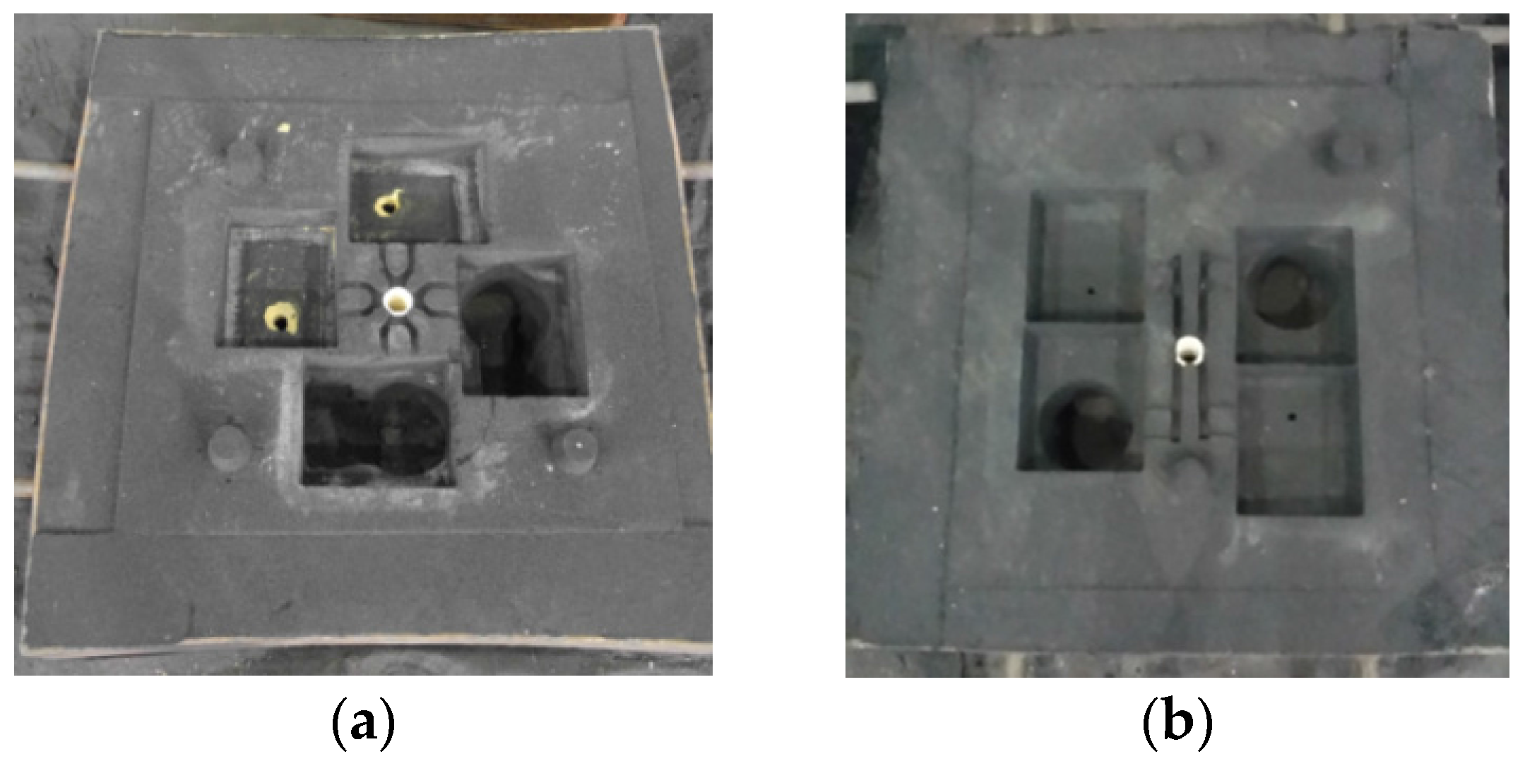
Figure 5 shows the mold used for casting the turbine housing. Figure 6 shows the fixed type mold with a rectangular cavity, which is the part connecting the gate system and the mold, for casting the turbine housing. Therefore, four turbine housings are combined into the empty rectangular space. Figure 7a shows the mold for the gate system where the runner and gate are arranged in a rectangular pattern, while Figure 6b shows the mold for the gate system where the runner is arranged as the number 11. Figure 7 is an image showing the turbine housing mold combined with the fixed mold. To investigate the effects of the cylindrical heater that uses the heat source, heaters were provided for two of the four turbine housing models to provide heat to the riser. Moreover, insulation materials were provided for the remaining two models. The schematic showing the experimental process is presented in Figure 8. The diameters of the risers were set at 10 mm and 20 mm. The experimental sequence is given in Table 1. The inner diameter of the cylindrical heater is 75 mm, and sand was stacked on the inner side of the heater and riser hole.
The molten metal was prepared by mixing and melting pig iron at 40%, recycled cast iron at 30%, and scrap at 30%. When the temperature of the molten metal was around 1400 °C, it was spheroidized using the sandwich method.
The riser was preheated by setting the heater temperature to 650 °C before pouring molten metal into the mold. When the temperature of the riser reached 650 °C, the molten metal was poured into the cast mold. Figure 9 is an image showing the riser being heated using the heater, while the molten metal is poured into the mold.
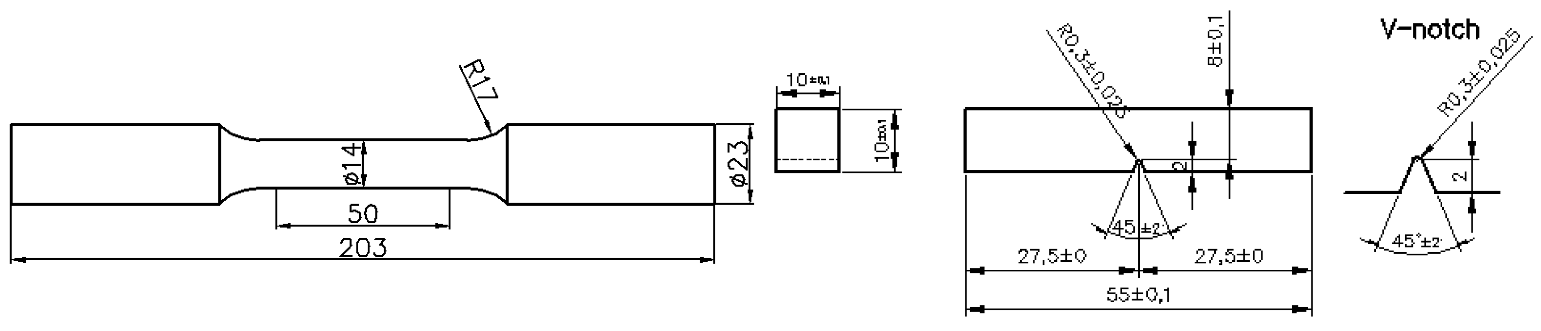
To analyze the mechanical properties of the turbine housing, the molten metal was poured into the mold as well as into a Y-block mold to prepare a Y-block. Figure 10 shows the shape of Y-block and position of specimens for tensile and impact test. Heat treatments were applied to the prepared Y-block to analyze the mechanical properties. For two hours, austenitizing treatments were applied to the samples at 950 °C. Moreover, austempering treatment was applied at 550 °C for two hours. The samples applied were cooled by opening the furnace door until the temperature normalized to room temperature. Samples were prepared from the Y-block, and the tensile test, Brinell hardness test, and impact test were conducted along with the observation of the sample microstructures. Figure 11 shows dimensions of specimen for tensile and impact test that follow ASTM A370. The tensile test was performed twice on the samples: prior to heat treatment and after the heat treatment conditions were applied. Moreover, the impact test was performed thrice, and the mean values were presented. The Brinell hardness was measured five times, and the average values were recorded, after the largest and the smallest values were discarded.
3. Results of Simulation and Experimental
3.1. Casting Simulation Results
The filling analysis results for the molten metal that was filled into the mold are presented in Figure 12. As the filling analysis involved a comparison between the filling behavior of the two gate systems, the heater was not set in the riser as part of the analysis conditions. For the filling analysis results, the amount of molten metal that was filled into the mold was expressed in three stages (37%, 70%, and 100%). The filling behaviors under the two heating conditions did not differ significantly. The molten metal flowed past the gate and the runner, right through the gate, finally reaching the housing. It filled the round portion of the turbine housing and finally filled the riser. After the molten metal filled the round portion of the housing, a vortex was generated. Moreover, the mold filling process was smooth because of the continuous filling of the molten metal into the riser. After the mold was completely filled, the temperature at the end was the lowest at around 1280 °C for both the heating conditions.
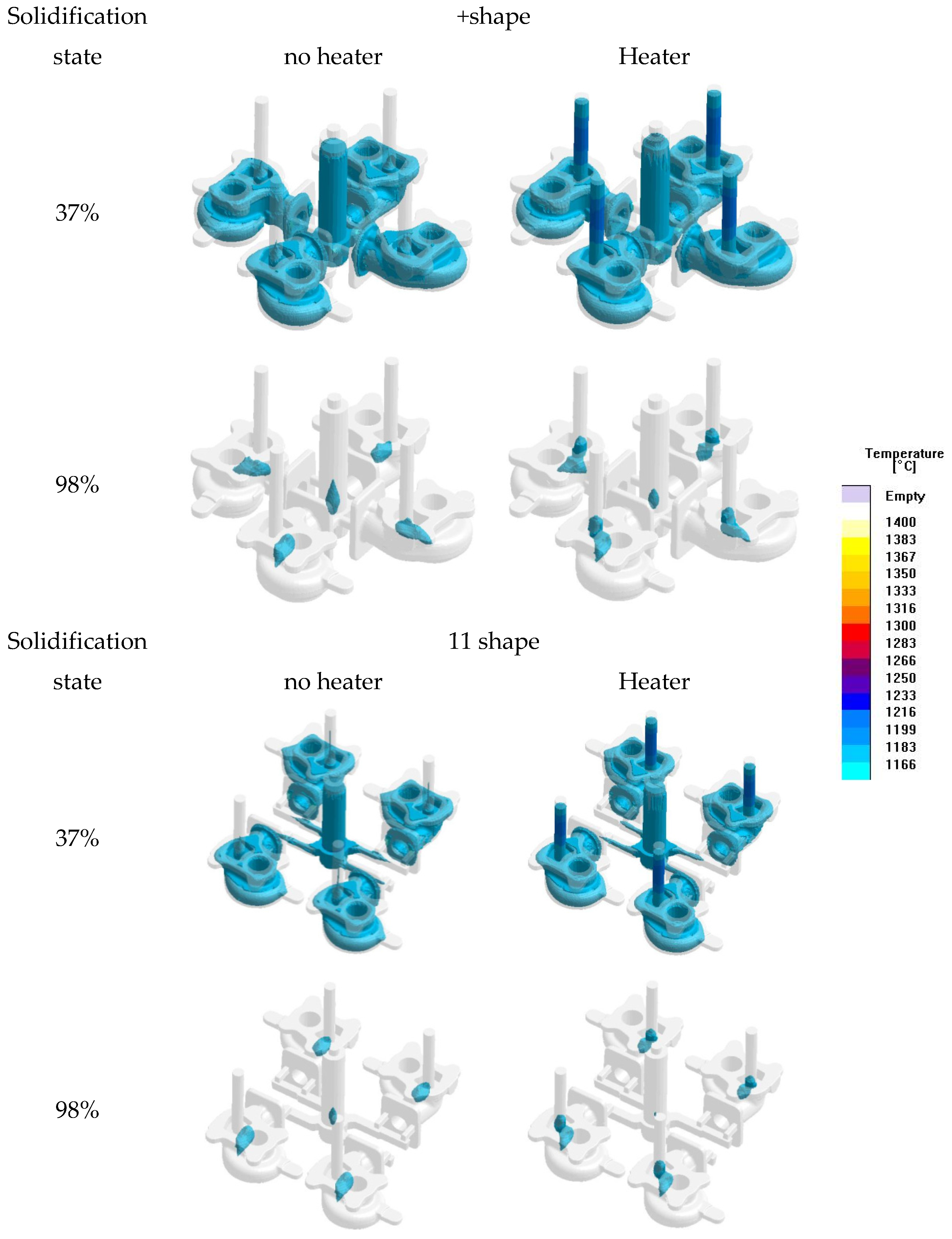
The solidification analysis results for the case of the heater attached onto the riser and the case involving the use of insulation material were compared. The solidification analysis results represent the amount of molten metal which has dropped lower than solidus line, and a higher solid fraction indicates the presence of a large amount of solidified molten metal. Figure 13 shows the solidification analysis results for the two types of gate systems: the left side shows condition in which heaters are applied to all the four; the right side shows the case where insulation material as used in all the risers. The same solidification behaviors were observed in both the gate systems. According to the solidification analysis result of the stage at 37%, without the heater, the riser solidified faster than the turbine housing. However, when a heater was implemented, the temperature in the riser was the highest. The diameter used in the analysis was 20 mm, indicating that the diameter of the riser has to be significantly large. The analysis results for 98% solidification showed that the portion where the turbine housing was thickest (the bolt connection part) solidified last if the heater was not implemented. Moreover, when the heater was implemented, the portion between the riser and bolt connection part of the turbine housing was the last to solidify. These results imply that the molten metal inside the riser continuously compensates for the shrinkage of the turbine housing while solidification progressed.
3.2. Casting Experiment Results
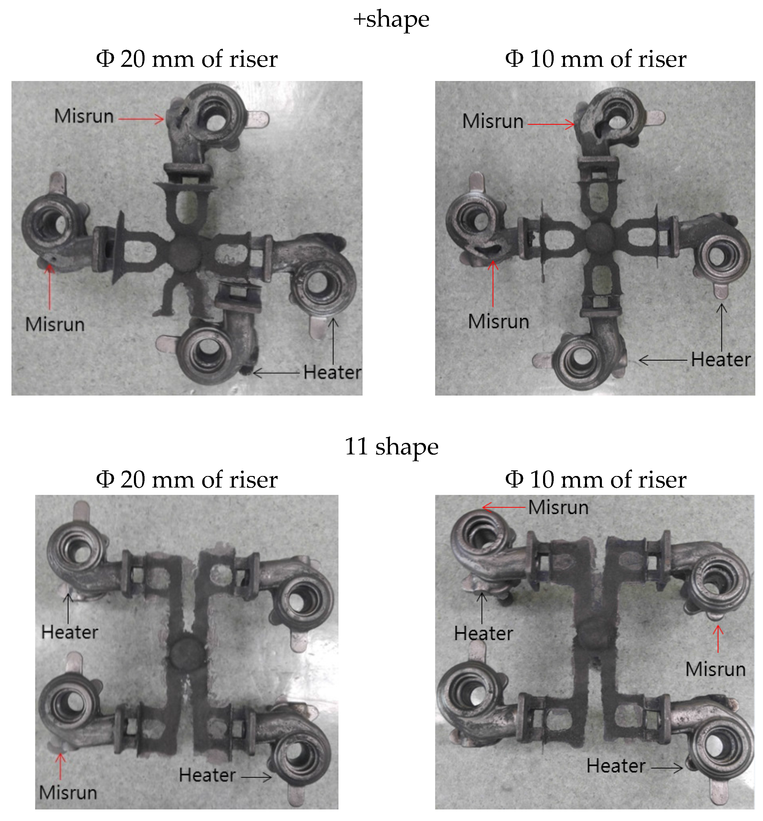
Figure 14 shows the casting products of the turbine housing, manufactured using the method shown in Table 1. As can be seen in the image, the heaters were implemented in two of the four turbine housings, while the other two had insulation material instead of heaters. There was a substantial difference between the results relating to both conditions. When the heater was implemented, complete products were manufactured regardless of the diameter of the gate system and riser. When the insulation material was used, significant misruns were generated near the round portion. The case of +shape gate system was comparable with that of 11 shape gate system, as misruns were far greater in the case where the heater was not used.
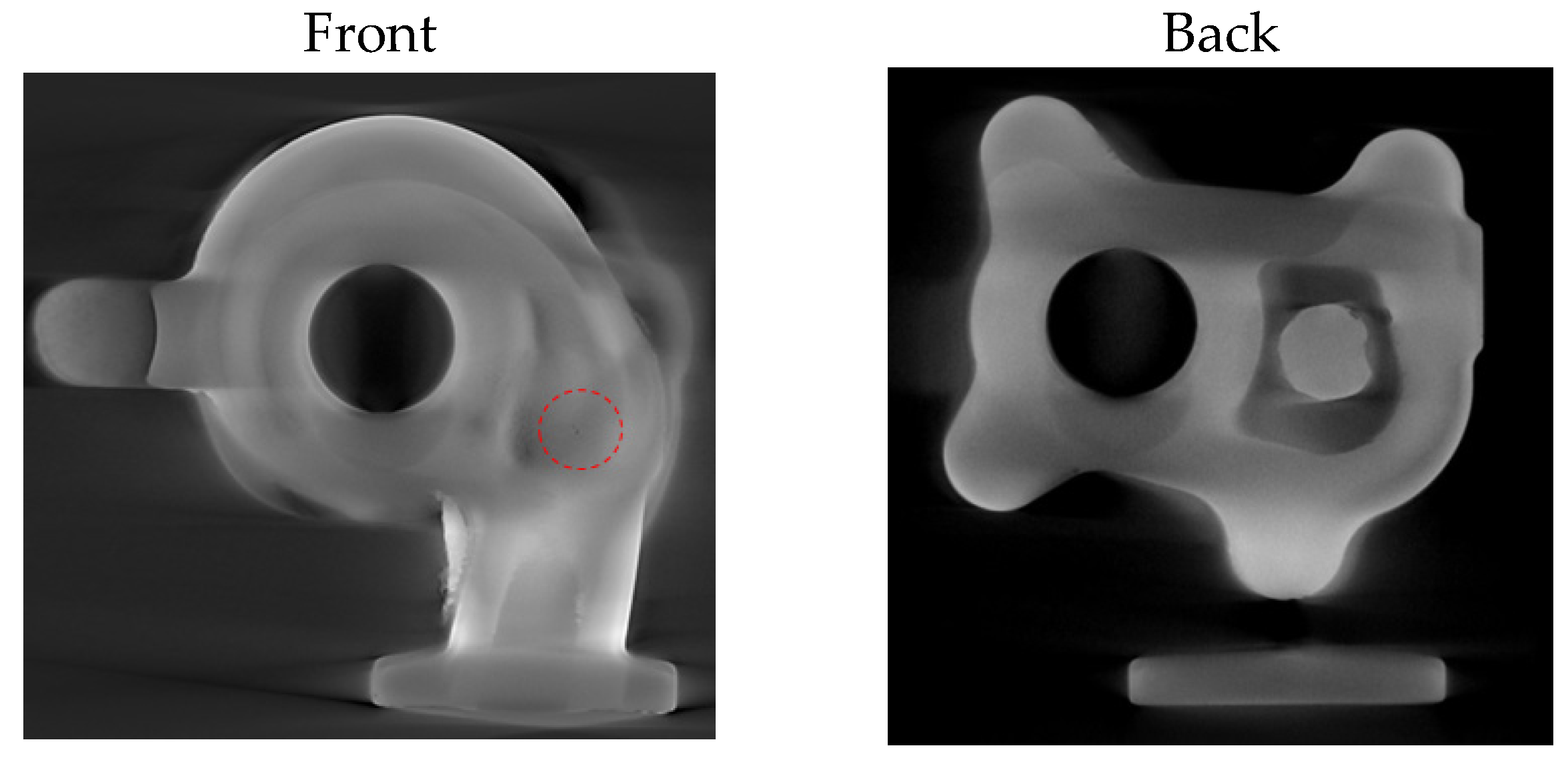
Figure 15 shows the X-ray inspection for the casted turbine housing with the heater applied. The shrinkage cavity generated was small (diameter 0.5 mm), and was situated at the round portion. It can be attributed to the continuous heating by the heater. Moreover, the riser was the last to solidify, sufficiently compensating for the shrinkage inside the turbine housing.
Table 4 shows the recovery rates of the cast turbine housings. The mass measurement values of the risers have diameters 10 mm and 20 mm, respectively. In case of the +shape gate system, where the diameter was set at 10 mm, the recovery rate was 75.6%; while for the riser having a diameter of 20 mm, the recovery rate was 68.7%. In the case of 11 shape gate system, with the riser having a diameter of 10 mm, a recovery rate of 75.7% is produced; while for the riser having a diameter 20 mm, the recovery rate was 67.2%. The primary reason for the differences between the recovery rates of the casting products and the ones calculated from the modeling file is the height of the gate. In the actual casting experiment, when the molten metal was poured into the mold, because the poured amount could not be accurately adjusted, the heights of the sprue in the castings were set differently. Therefore, the recovery rate in the actual casting was measured as a lower value, in comparison to that calculated from the modeling file.
Table 5 presents the mechanical properties prior to the heat treatment and after heat treatments are applied. The tensile strength and elongation of the cast Y-block were 545 MPa and 7.0%, respectively, the Brinell hardness was 173 HB, while the impact energy level was 4.3 J. According to the heat treatment conditions, the physical properties of the castings differed greatly. The castings had 620 MPa of tensile strength, 4.5% of elongation, 220 HB of Brinell hardness and 1.6 J of impact resistance, respectively. The tensile strength and Brinell hardness were increased compared with the castings before heat treatment, while elongation and impact energy were decreased.
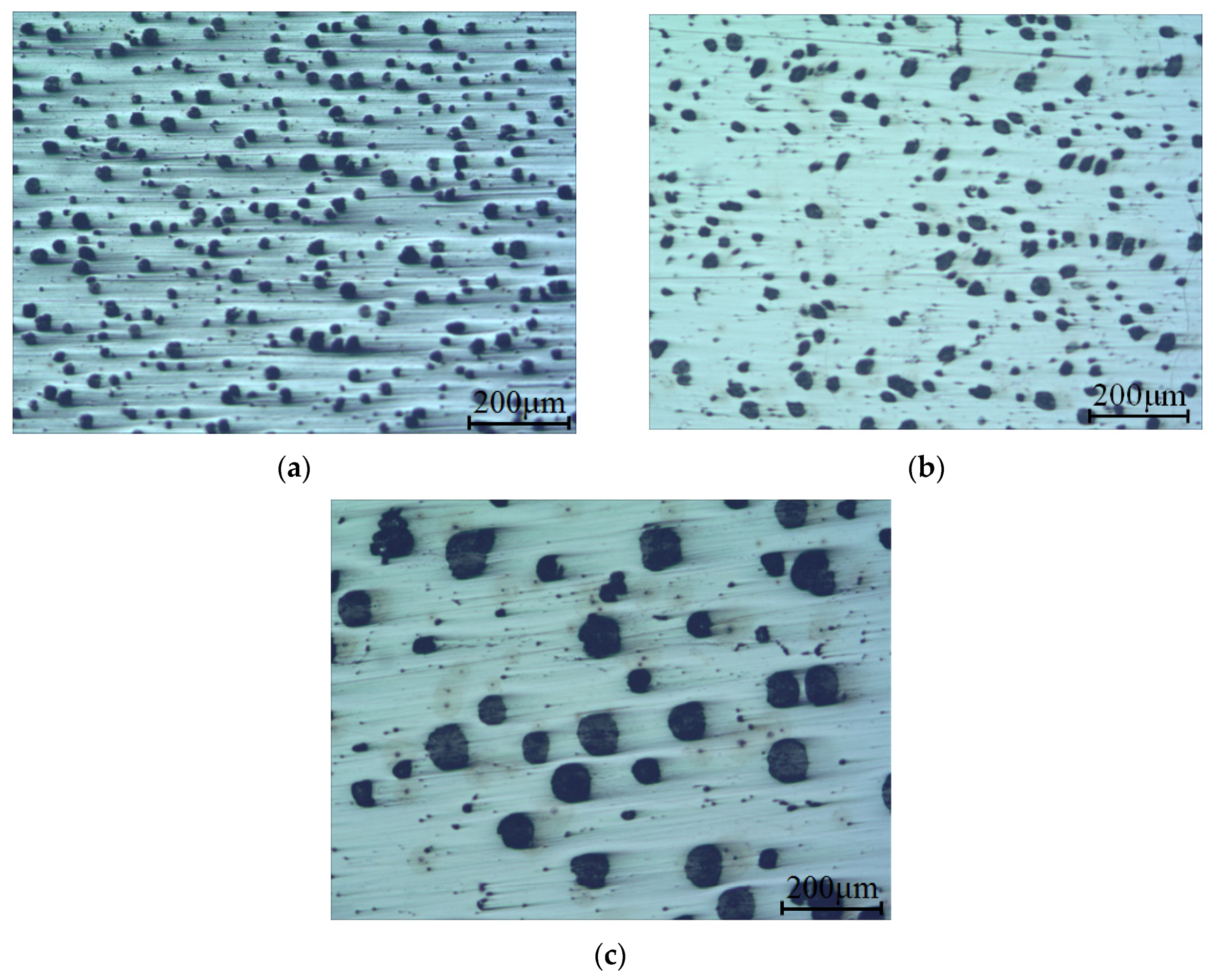
Figure 16 shows the microstructures of the turbine housing castings and Y-block casting. As shown in Figure 16a,b heated turbine housing has more carbon particles than non-heated turbine housing. Also, carbon particles of heated turbine housing exhibits that more spheroid in shape than that of non-heated turbine housing. Heated turbine housing had Brinell hardness values of 186 HB and non-heated turbine housing had 175 HB. This was presumed to be because the carbon particles were more densely distributed. The dimensions of the carbon particles differed greatly in comparison with turbine housing and Y-block casting. Considerably smaller carbon particles were found in the turbine housing than in the Y-block, with a greater number of particles. The turbine housing was considerably thinner when compared with the Y-block, and had many curved portions. In case of the Y-block, carbon particles could grow freely. However, the growth of the carbon particles in the turbine housing was restricted, due to the thinner turbine housing, resulting in a slower growth of carbon particles, which further explains the number of carbon particles. The Y-block had 170 HB that was lower than turbine housing because of the large carbon particles which used to be the liquid phase.
4. Conclusions
In this study, heat was provided in the riser using a cylindrical heater for the casting of the turbine housing. The results obtained are as follows:
- (1)
- The casting simulation showed that with the heater implemented in the riser, the molten metal was the last to solidify, resulting in continuous compensation for the shrinkage that occurred during the solidification of the product. Moreover, the implementation of insulation material quickened the solidification of the molten metal in the riser more than in the turbine housing; therefore, the function of the riser could not be achieved. The experimental results suggested that when the insulation material is implemented in the riser for the casting of the turbo housing, the diameter of the riser has to be significantly greater than 20 mm.
- (2)
- A mold was designed with one-time casting of the four turbine housings. For the two risers in the casting experiment of the turbine housing, heaters were implemented, while the insulation material was provided for the other two risers. With the insulation material, defects were generated significantly when compared with the case of the heater implementation, which produced no defects. The X-ray inspection results showed that just one micro cavity with a diameter 0.5 mm was found in the turbine housing casting, with the heater implemented in the riser. It was therefore verified that the implementation of a cylindrical heater could drastically minimize the size of the riser.
- (3)
- Molten metal was poured into the mold for turbine housings as well as into a Y-block mold for test of tensile and impact. The mechanical properties were investigated; the tensile strength and elongation rate were 545 MPa and 7.0%, respectively. The Brinell hardness was 173 HB, and the impact energy was 4.3 J. Austenitizing treatment, applied at 950 °C for two hours, followed by another austempering applied at 550 °C for two hours, could improve the cast strength when compared with the cast strength before the heat treatment is applied.
Acknowledgments
This work was supported by a National Research Foundation of Korea (NRF) grant funded by the Korea government (MSIP) through GCRC-SOP and this work also was supported by the Industry Convergence Fundamental Technology Development Program (10054771, Technology development of gravity casting without riser for cast iron turbocharger housing) funded by the Ministry of Trade, Industry and Energy (MOTIE).
Author Contributions
Chul Kyu Jin designed mold of casting by performing the simulation. Chul Kyu Jin and Hyung Yoon Seo conducted casting experiment and analysed the results. Chung Gil Kang managed and examined the results of simulation and experiment. All authors have contributed to discussing and revising.
Conflicts of Interest
The authors declare no conflict of interest.
References
- Casting Design Handbook; American Society for Metals: Metals Park, OH, USA, 1962; pp. 269–299.
- Metals handbook. Forging and Casting, 8th ed.; American Society for Metals: Metals Park, OH, USA, 1970; pp. 335–374.
- DeGarmo, E.P.; Black, J.P.; Kohser, R.A. Materials and Process in Manufacturing. In Solutons Manual to Accompany, 9th ed.; John Wiley and Sons Ltd.: New York, NY, USA, 2003; pp. 107–115. [Google Scholar]
- Casting-Wikipedia. Available online: https://en.wikipedia.org/wiki/Casting (accessed on 7 February 2017).
- Tavakoli, R.; Davami, P. Feeder growth: A new method for automatic optimal feeder design in gravity casting processes. Str. Multidisc Optim 2009, 39, 519–530. [Google Scholar] [CrossRef]
- Campbell, C. Casting; Butterworth-Heinemann Ltd.: Oxford, UK, 1991. [Google Scholar]
- Guleyupoglu, S. Casting process design guidelines. AFS Trans. 1997, 105, 869–876. [Google Scholar]
- Turbocharger-Wikipedia. Available online: https://en.wikipedia.org/wiki/Turbocharger (accessed on 12 March 2017).
- Lagad, P.P. Air entrapment analysis of casting (turbine housing) for shell moulding process using simulation technique. Inter. J. Eng. Res. Gen. Sci. 2014, 2, 143–149. [Google Scholar]
- Fragassa, C.; Radović, N.; Pavlovic, A.; Minak, G. Comparison of mechanical properties in compacted and spheroidal graphite irons. Tribol. Ind. 2016, 38, 45–56. [Google Scholar]
- Fragassa, C.; Minak, G.; Pavlovic, A. Tribological aspects of cast iron investigated via fracture toughness. Tribol. Ind. 2016, 38, 1–10. [Google Scholar]
- Fragassa, C.; Zigulic, R.; Pavlovic, A. Push-pull fatigue test on ductile and vermicular cast irons. Eng. Rev. 2016, 36, 269–280. [Google Scholar]
- Radović, N.; Morri, A.; Fragassa, C. A study on the tensile behaviour of spheroidal and compacted graphite cast irons based on microstructural analysis. In Proceedings of the 11th IMEKO TC15 Youth Symposium on Experimental Solid Mechanics, Brasov, Romania, 2 June 2012; pp. 185–190. [Google Scholar]
- Li, P.; Wang, J.J.; Ge, D.C.; Sui, G.H.; Chen, G.H.; Wang, G.W.; Wang, G.W.; Tang, B.; Tang, W.M. Microstructures and mechanical properties of grey irons by adding high-content steel scrap. Int. J. Cast Met. Res. 2016, 29, 369–375. [Google Scholar] [CrossRef]
- Sturm, J.C.; Busch, G. Cast iron-a predictable material. In Proceedings of the World Foundry Congress 2010, Hangzhou, China, 16–20 October 2010; pp. 1–9. [Google Scholar]
Figure 1.
Schematic of turbine housing (unit: mm).
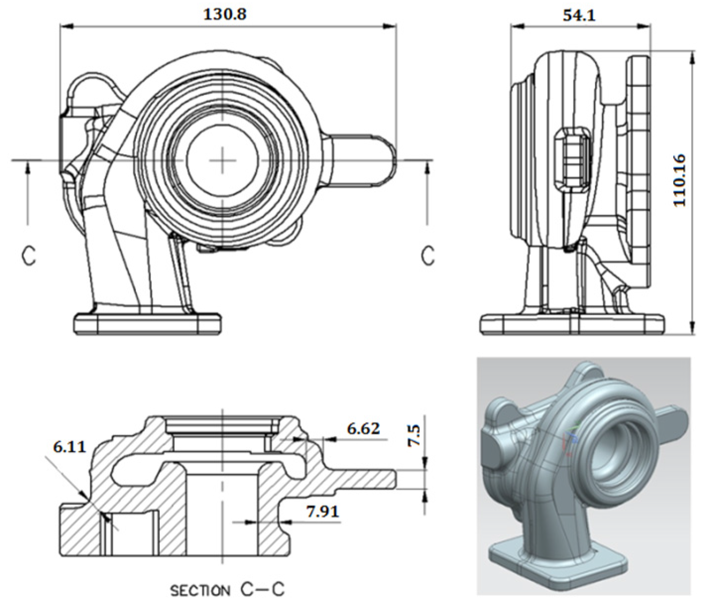
Figure 2.
Gate systems for turbine housings (unit: mm): (a) +shape and (b) number 11 shape.

Figure 3.
Cavity shape of mold: (a) +shape and (b) letter 11 shape.

Figure 4.
Design of cylindrical heater for casting simulation: (a) +shape and (b) number 11 shape.
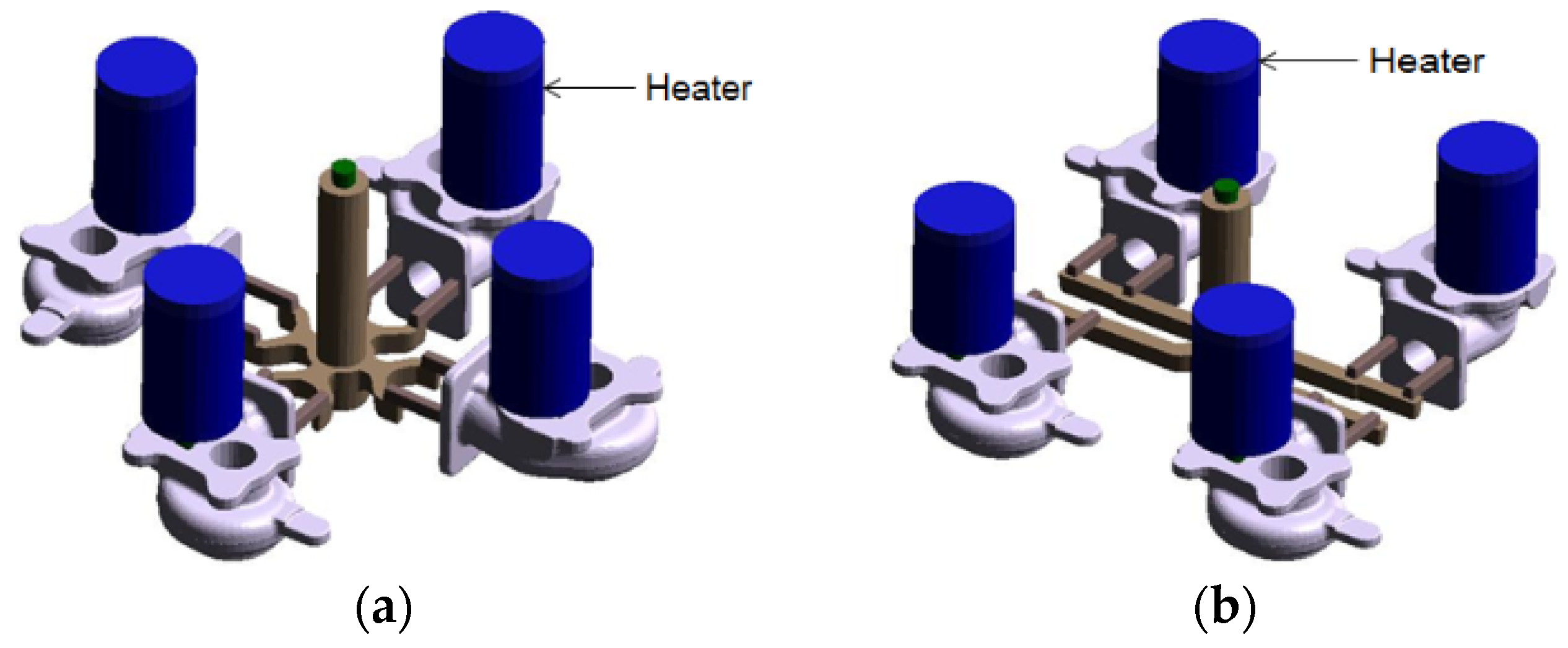
Figure 5.
Mold of turbine housing: (a) upper mold and (b) lower mold.

Figure 6.
Fixed mold: (a) +shape and (b) number 11 shape.

Figure 7.
Fixed mold assembled with turbine housing mold: (a) +shape and (b) number 11 shape.
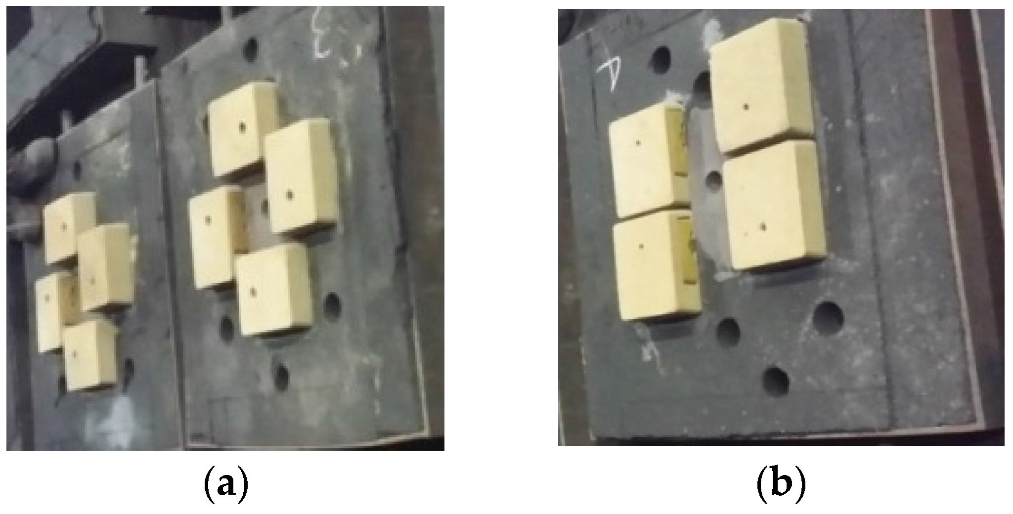
Figure 8.
Experimental method for cylindrical heater: (a) +shape and (b) number 11 shape.
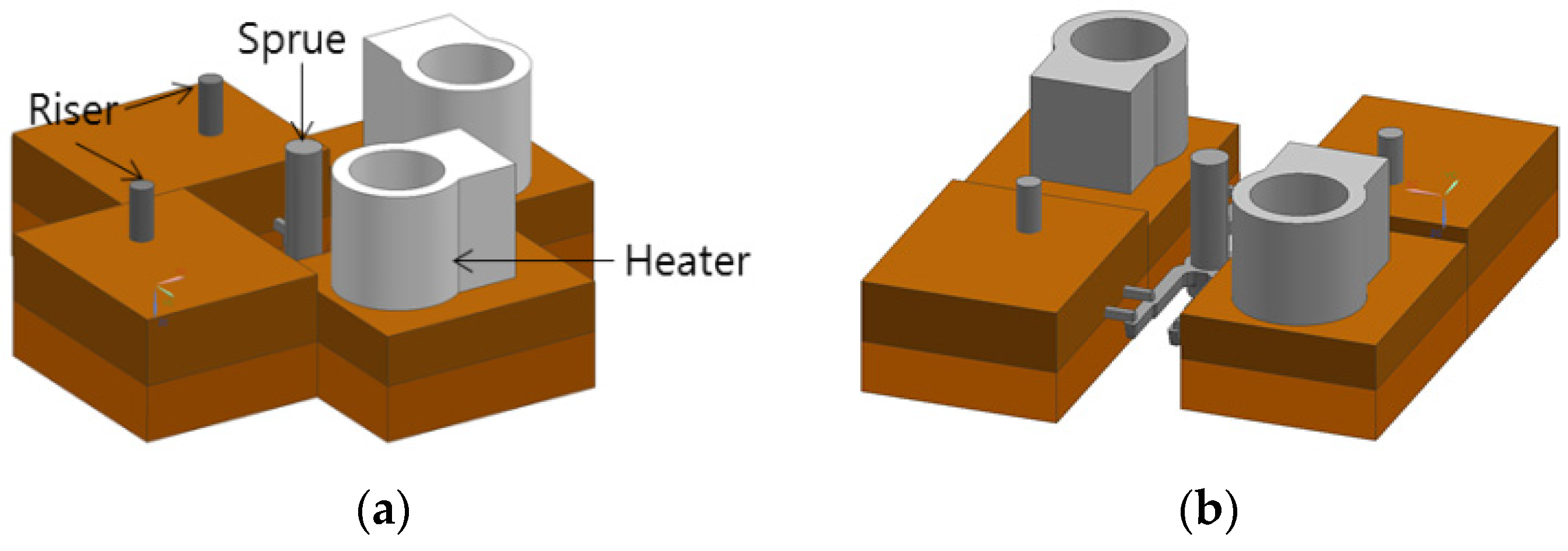
Figure 9.
Heating risers used for cylindrical heaters.
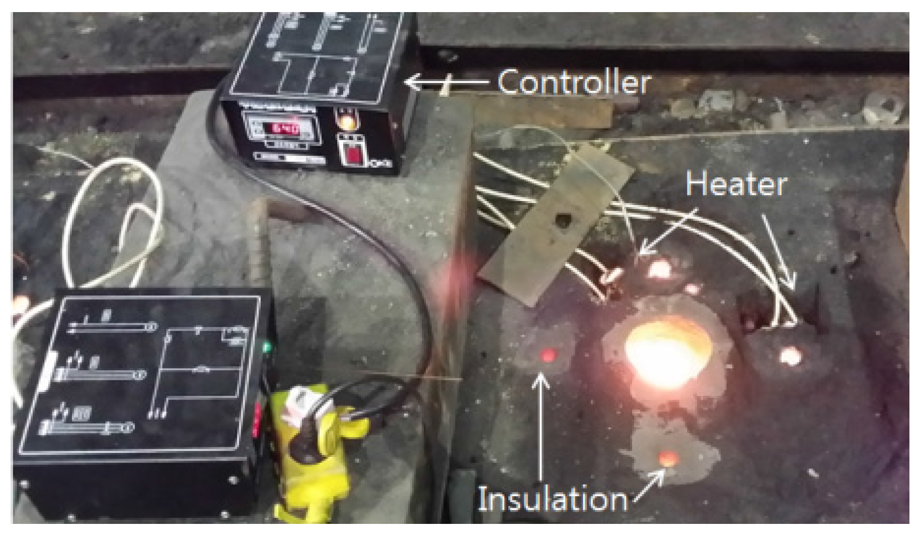
Figure 10.
Dimensions of Y-block and position of specimens for tensile and impact test.
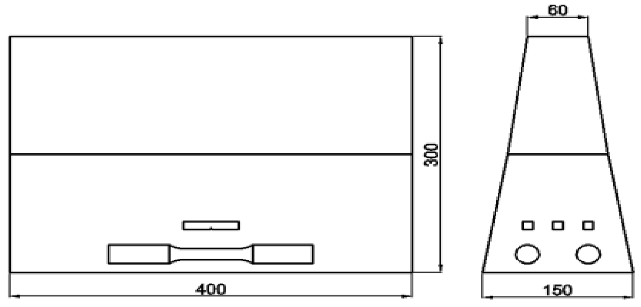
Figure 11.
Dimensions of tensile and impact specimen.

Figure 12.
The comparison of filling behavior between two gate systems.
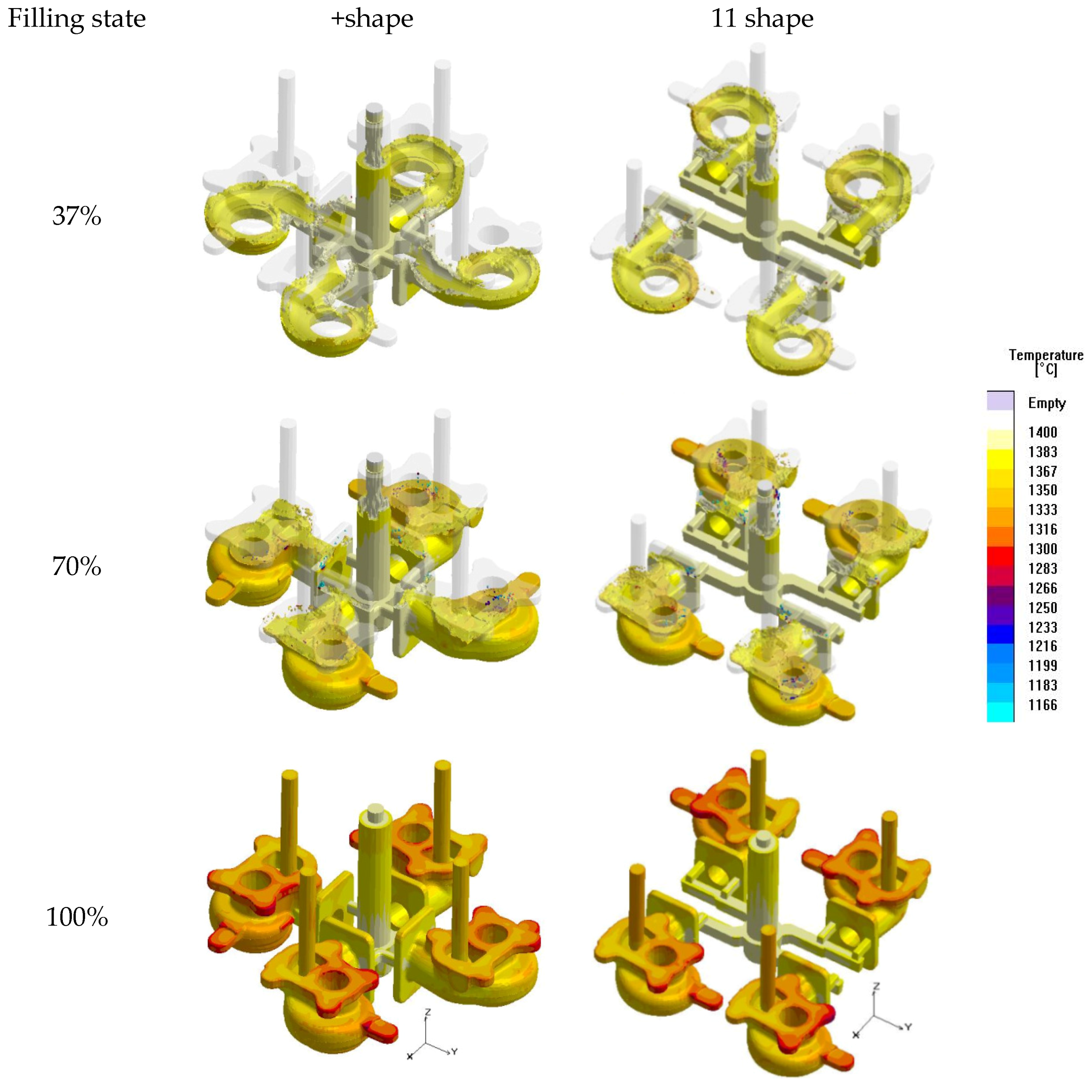
Figure 13.
The comparison of solidification behavior between two gate systems.

Figure 14.
Casted turbine housings.

Figure 15.
Casted turbine housings.

Figure 16.
Microstructures of (a) turbine housing with heater; (b) turbine housing without heater and (c) Y-block.
Figure 16.
Microstructures of (a) turbine housing with heater; (b) turbine housing without heater and (c) Y-block.


Table 1.
The size of riser and recovery rate.
| Classification | +Shape Gate System | +Shape Gate System | 11 Shape Gate System | 11 Shape Gate System |
|---|---|---|---|---|
| Diameter of Riser | Φ 10 mm | Φ 20 mm | Φ 10 mm | Φ 20 mm |
| Weight of Riser | 0.21 kg | 0.84 kg | 0.21 kg | 0.84 kg |
| Recovery Rate | 82% | 77% | 80% | 75% |
Table 2.
Chemical compositions of spheroidal graphite cast iron (GCD) 500 (wt %).
| C | Si | Mn | Cu | Mg | P | S |
|---|---|---|---|---|---|---|
| 3.46 | 2.25 | 0.29 | 0.25 | 0.06 | 0.014 | 0.011 |
Table 3.
Conditions of sand casting simulation.
| Classification | Value | Classification | Value |
|---|---|---|---|
| Pouring temperature | 1400 °C | Solidus of melt | 1166 °C |
| Sand temperature | 20 °C | Liquidus of melt | 1169 °C |
| Heater temperature | 650 °C | Latent heat | 257 kJ/kg |
| Heat transfer coefficient (between casting and sand mold) | 300 W/m2K | ||
Table 4.
Recovery rate of cast turbine housing.
| Classification | +Shape Gate System | +Shape Gate System | 11 Shape Gate System | 11 Shape Gate System |
|---|---|---|---|---|
| Diameter of Riser | Φ 10 mm | Φ 20 mm | Φ 10 mm | Φ 20 mm |
| Weight of Riser | 0.19 kg | 1.20 kg | 0.19 kg | 1.19 kg |
| Weight of Turbine Housing | 6.53 kg | 6.52 kg | 6.51 | 6.52 |
| Weight of Gate System | 1.88 kg | 1.76 kg | 1.89 | 1.99 |
| Recovery Rate | 75.6% | 68.7% | 75.7% | 67.2% |
Table 5.
Mechanical properties of the Y-block before and after heat treatment.
| classification | Ultimate Tensile Stress (MPa) | Elongation (%) | Impact Energy (J, 20 °C) | Brinell Hardness (HB) |
|---|---|---|---|---|
| As Cast | 545 | 7.0 | 4.3 | 173 |
| Heat Treatment | 620 | 4.5 | 1.6 | 220 |
© 2017 by the authors. Licensee MDPI, Basel, Switzerland. This article is an open access article distributed under the terms and conditions of the Creative Commons Attribution (CC BY) license (http://creativecommons.org/licenses/by/4.0/).
Share and Cite
MDPI and ACS Style
Jin, C.K.; Seo, H.Y.; Kang, C.G. Heating System for Riser Size Minimizing in Sand Casting Process and Its Experimental Verification. Metals 2017, 7, 130. https://doi.org/10.3390/met7040130
AMA Style
Jin CK, Seo HY, Kang CG. Heating System for Riser Size Minimizing in Sand Casting Process and Its Experimental Verification. Metals. 2017; 7(4):130. https://doi.org/10.3390/met7040130
Chicago/Turabian StyleJin, Chul Kyu, Hyung Yoon Seo, and Chung Gil Kang. 2017. "Heating System for Riser Size Minimizing in Sand Casting Process and Its Experimental Verification" Metals 7, no. 4: 130. https://doi.org/10.3390/met7040130
Note that from the first issue of 2016, this journal uses article numbers instead of page numbers. See further details here.