Effect of Parameters on Internal Crack Healing in 30Cr2Ni4MoV Steel for 600-Ton Ultra-Super Ingots

1
Department of Mechanical Engineering, Tsinghua University, Beijing 100084, China
2
Key Laboratory for Advanced Materials Processing Technology of Ministry of Education, Tsinghua University, Beijing 100084, China
3
HBIS Group Technology Research Institute, Shijiazhuang 050023, China
*
Author to whom correspondence should be addressed.
Metals 2017, 7(4), 149; https://doi.org/10.3390/met7040149
Submission received: 21 March 2017
/
Revised: 15 April 2017
/
Accepted: 19 April 2017
/
Published: 21 April 2017
Abstract
:The effect of parameters on internal crack healing in 30Cr2Ni4MoV steel for 600-ton ultra-super ingots was systematically investigated. The results show that the degree of crack healing increases with increasing healing temperature, holding time, reduction ratio, and hot pressure, and with decreasing strain rate. Internal crack healing in 30Cr2Ni4MoV steel should be conducted at less than 1200 °C to avoid grain coarsening. Hot pressure, in the high-temperature elastic zone and perpendicular to the crack faces, not only promotes the rapid crack healing, but also prevents grain coarsening of the matrix.
1. Introduction
Heavy forgings are key parts of electric power, metallurgy, petrochemical, shipbuilding, nuclear energy, and other industries. However, cavity-type defects, such as cracks and voids, are inevitable during the manufacturing process of large heavy forgings [1]. Attributing to solidification characteristics of heavy ingots [2], especially ultra-super ingots, internal cavity-type defects, such as shrinkage cavities and porosity, which can be considered as voids or cracks, often occur during the inhomogeneous solidification. Though most of the cavity-type defects can be closed and eliminated by a proper forging process, some cavity-type defects still remain in the heavy forgings. Furthermore, cracks and other cavity-type defects may be induced by inhomogeneous deformation during the forging and subsequent processes. These cavity-type defects will severely deteriorate the mechanical properties of the heavy forgings and be the primary cause of rejects [3,4]. In addition, as steel ingots increase in size and weight, these problems will become more prominent. Therefore, healing cracks and eliminating cavity-type defects in the heavy forgings will not only reduce rejection rates, but also improve their mechanical properties and service life. This will save large amounts of energy and greatly benefit economy and ecology.
It is well-known that crack propagation and healing in metallic materials are two contrary processes. Griffith [5] proposed that cracking was not reversible, but a very narrow crack could be healed by a heat treatment method if the temperature was sufficient to bring the atoms on either side of the crack within mutual range by thermal agitation. Compared with crack propagation, crack healing in metallic materials [6,7,8,9] have been studied for only two decades. This kind of investigation is still in the early stage. Influencing factors of crack healing in metallic materials are very complex. Based on the controllability, the influencing factors can be divided into the external and internal. The internal factors include chemical composition, grain size, crack type, crack orientation, residual stress, and so on, and the external factors consist of healing temperature, holding time, cooling mode, reduction, strain rate, deformation pass, load, and environmental atmosphere.
In existing research works, the emphasis of crack healing has been placed on the external factors. Yu et al. [10] systematically analyzed crack healing in a low-carbon steel under hot plastic deformation and pointed out that the degree of crack healing increased with increasing heating temperature, reduction ratio, and holding time, and with decreasing numbers of deformation passes and strain rate. Li et al. [11] investigated crack healing behavior of 12% Cr ultra-super-critical rotor steel, and found that the heating temperature was a decisive factor of crack healing, and the crack started healing at the temperature of 900–950 °C. Dong et al. [12] studied hydrogen-induced crack healing in a carbon steel by heat treatment, and the results indicated that a hydrogen-induced crack can be completely healed by cyclic heat treatment between room temperature and 1000 °C. Investigation of crack healing behavior of 45 steel has been performed using a normalizing treatment by Xiao et al. [13], and the experimental results showed that crack healing mainly depended on the normalizing temperature rather than the holding time, and the healing band in the crack zone consisted of fine recrystallized ferrite grains. Until now, the effect of different healing parameters on crack healing in metallic materials, especially in ultra-super forgings, is still unclear. There is still a lack of reliable applications to heal cracks in large ingots and heavy forgings.
In the present study, a series of tests on crack healing in 30Cr2Ni4MoV steel were carried out using a Gleeble 1500D thermomechanical simulator The effect of parameters including healing temperature, holding time, reduction ratio and strain rate on crack healing were studied. Considering that heavy forgings or workpieces cannot be further deformed after forming, the effect of hot pressure in the high-temperature elastic zone on crack healing in 30Cr2Ni4MoV steel was emphatically investigated.
2. Experimental Procedure
The material used in this study was as-forged 30Cr2Ni4MoV steel deprived from a 600-ton ultra-super ingot used for the integral solid low-pressure turbine rotor in a conventional island of an AP1000 nuclear power plant. The chemical composition of the steel (wt %) was measured as shown in Table 1. The microstructure of internal crack zone before and after healing treatment was examined using an OLYMPUS-BX51M optical microscope (OM) and a JSM-7100F field emission scanning electron microscope (FEG-SEM).
2.1. Pre-Crack Method
Artificial cracks are generally used to investigate the influence of parameters on crack healing. Internal cracks were introduced into the samples via a drilling and compression method. Firstly, cylindrical samples of 8 mm in diameter and 12 mm in height were machined using a wire-cut electrical discharge machine. A through hole 2 mm in diameter was subsequently drilled in the middle of the cylindrical sample side face. The scraps and oil in the holes were cleaned using acetone and ethanol, and then the holes were sealed with Φ2 × 2 mm sample pieces of the same material, then the gaps between the pieces and the samples were laser welded. Finally, the cylindrical samples were subjected to a 45% height reduction at 800 °C with a nominal strain rate of 0.1 s−1 using a Gleeble 1500D thermomechanical simulator With these steps, linear internal cracks were obtained in the samples, as shown in Figure 1.
2.2. Crack Healing Tests
In order to investigate the effect of healing temperature and holding time, the samples with the pre-cracks were heated at a heating rate of 10 °C/s from 800 °C to the desired healing temperatures, and a series of crack healing tests were performed in the temperature ranges of 900–1200 °C (in steps of 100 °C) for 5, 10, 15, 30 and 60 min, respectively.
To investigate the effect of reduction ratio on crack healing, the pre-cracked samples were further subjected to 5%, 10%, 15%, 20% and 30% height reduction at 1000 °C with a nominal strain rate of 0.1 s−1.
Considering that some heavy forgings and workpieces are not allowed to be further deformed after forming, the effect of hot pressure in the high-temperature elastic zone on crack healing in the experimental steel was studied, the tests were conducted at 900–1200 °C for 30 min under 2–6 MPa (in steps of 2 MPa) (16.32–48.96 kgf).
After healing treatment, these samples were rapidly quenched in water to freeze the microstructure of the crack healing zone. The samples were cut along their longitudinal axis and perpendicular to the longitudinal axis of the original through holes. The sections were ground and polished using progressively finer grades of silicon carbide paper and diamond suspension, then ultrasonically cleaned, and finally etched using a 4% nital and picric acid-saturated water solution.
In order to systematically investigate the effect of healing parameters, the microstructure of the matrix under various healing conditions were observed, and grain sizes of the matrix were measured by the line intercept method based on Standard GB/T6394-2002.
3. Results and Discussion
3.1. Pre-Crack Morphology
Figure 1 shows the typical morphology of the artificial pre-crack. The pre-crack width varied along the length. The dashed region was the central area of the pre-crack with the width of approximately 3 μm. However, in either end area, the pre-crack width ranged from 5 to 15 μm. The pre-crack variation in width was primarily attributed to the non-uniform plastic deformation of the cylindrical samples during hot compression. In order to investigate and compare the effect of parameters on crack healing, this paper only aimed at crack healing around the central area.
3.2. Influence of the Healing Temperature
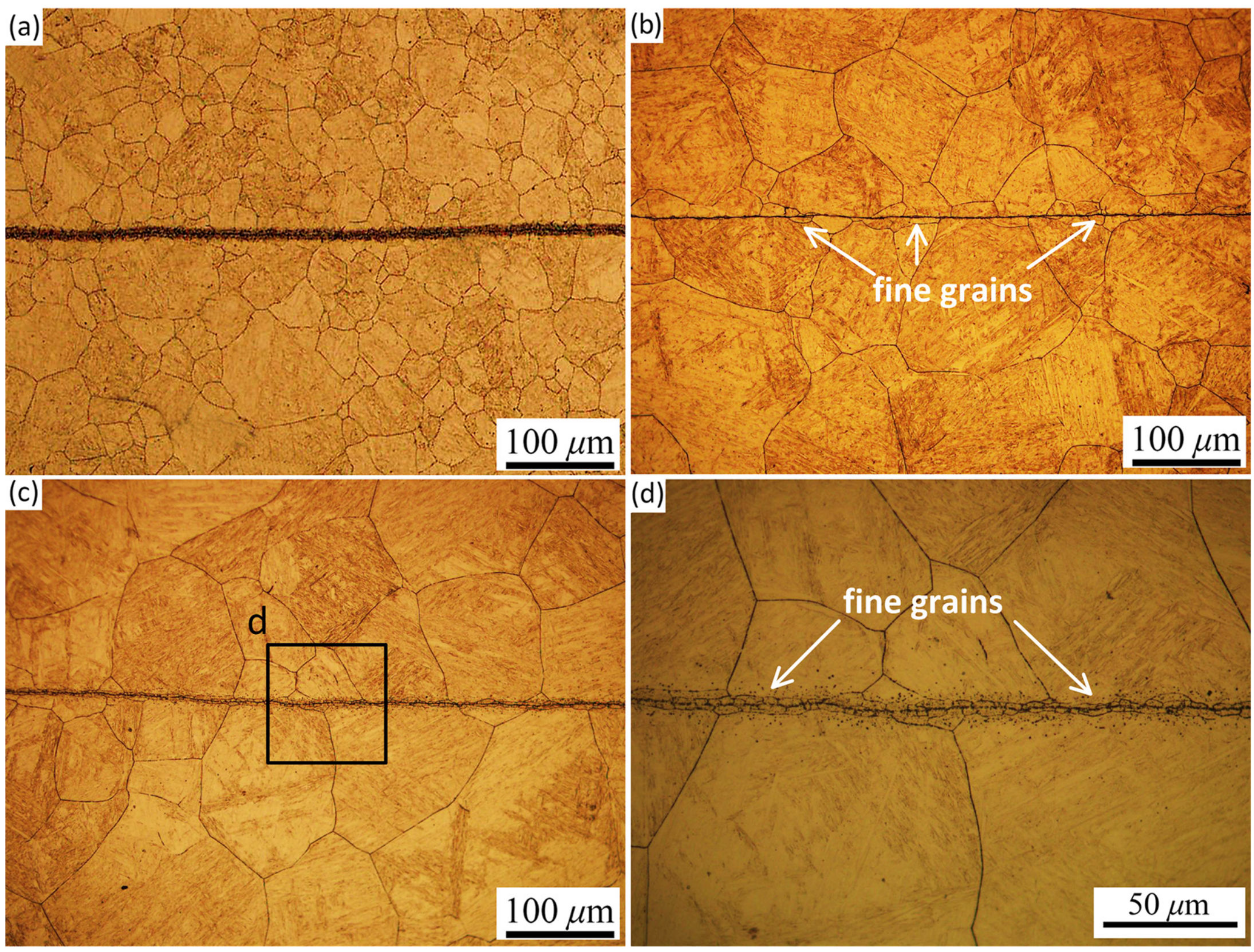
Figure 2 shows SEM micrographs of the crack healing zone at different healing temperatures for 60 min and Figure 3 shows OM micrographs of the crack healing zone at different healing times for 60 min. As shown in Figure 2a,b, at a healing temperature of 1000 °C, the crack gap was fully filled by massive fine grains, as indicated by the black arrow. The microstructure of the crack healing zone was obviously distinct from that of the matrix, and the width of the fine grain band was about 8 μm, which was larger than that of the pre-crack. The formation of the fine grains indicated that recrystallization had occurred in the crack healing zone. The difference in width and the occurrence of recrystallization were mainly due to a large amount of strain energy and crack surface energy in the crack zone composed of crack surfaces and the matrix near the crack, which provide sufficient energy for recrystallization. As a result, these new fine grains not only formed in the matrix close to the pre-crack but also filled the pre-crack gaps, and the width of fine grain band was larger than that of the pre-crack.
In addition, a very interesting phenomenon was found that there were three clear dividing lines in the crack healing zone, as shown in Figure 2b. The two dividing lines, indicated by white arrows, were interfaces between the newly-formed fine grains in the crack healing zone and the coarse grains in the matrix. The middle line, indicated by yellow arrows, represented the meeting interface of the newly-formed fine grains which grew from both sides of the crack. The similar phenomena were also discovered during electro-healing cracks in nickel [14,15]. This implied that the newly-formed fine grains had grown at a nearly identical growth rate from both sides towards the center of the pre-crack. Additionally, there were some micro-voids in the region of the center line. After healing at 1100 °C, the width of crack zone decreased, as shown in Figure 2c, while the three dividing lines still remained in the crack healing zone. The crack healing zone narrowed due to the growth of fine grains at 1100 °C. The narrower the crack healing zone became, the higher the degree of crack healing. Previous studies [4,16] on crack healing in metallic materials have also confirmed that recrystallization and grain growth occurred during the crack healing. It was clearly seen in Figure 3c,d that massive fine grains formed and recrystallization occurred in the crack healing zone. When the healing temperature raised up to 1200 °C, the crack healing zone completely disappeared, and only the meeting line still remained in the center of the original pre-crack. Some parts of the center line began to curve and become grain-boundary triple junctions, as shown in Figure 2d.
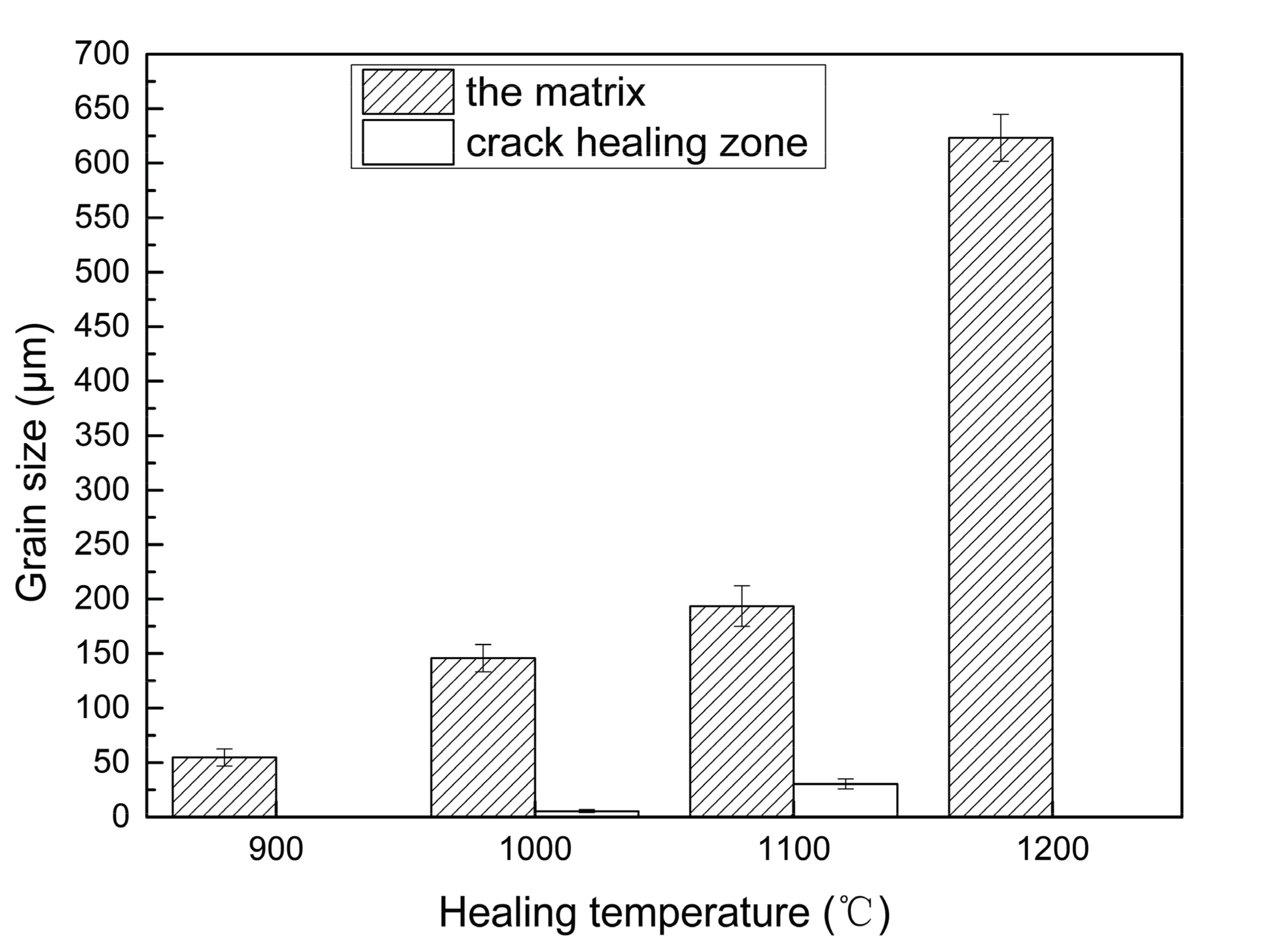
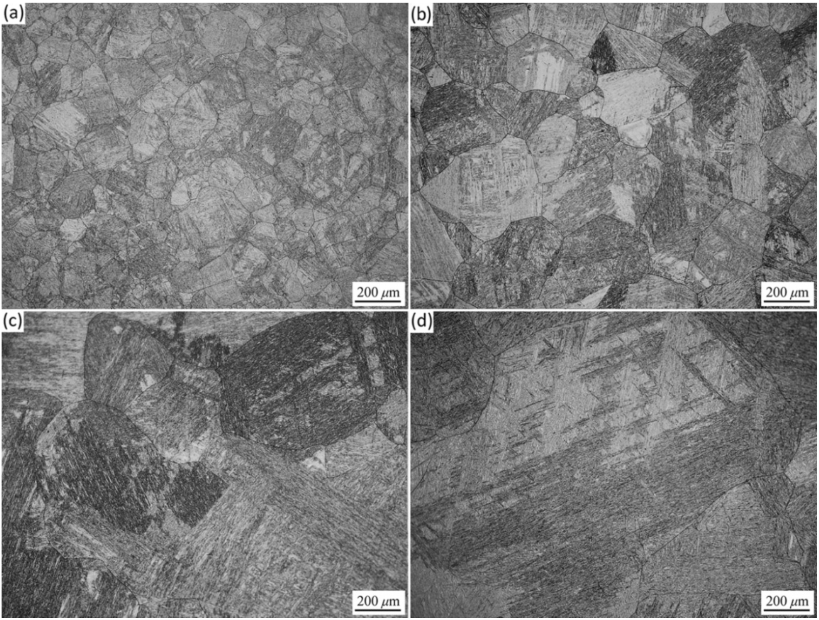
Microstructures of the matrix at different healing temperatures for 60 min are shown in Figure 4, and the corresponding grain sizes are presented in Figure 5. Obviously, the grain sizes increased markedly with increasing healing temperatures, as shown in Figure 4 and Figure 5. After healing at 900 °C for 60 min, the grain size of the matrix was about 54.57 μm, similar to the ingot material as received. When healing temperatures were 1000 °C and 1100 °C, the grains of the matrix grew to 145.69 μm and 193.48 μm, respectively. Additionally, the sizes of fine grains formed in the crack healing zone at 1000 °C and 1100 °C were also measured, and the values were 5.41 μm and 30.4 μm, respectively, both of which were smaller than that of the matrix at 900 °C for 60 min. When the healing temperature was further raised to 1200 °C, the grains of the matrix grew sharply and coarsened up to a size of 623.2 μm. Meanwhile, the fine grains in the crack healing zone completely disappeared.
3.3. Influence of the Holding Time
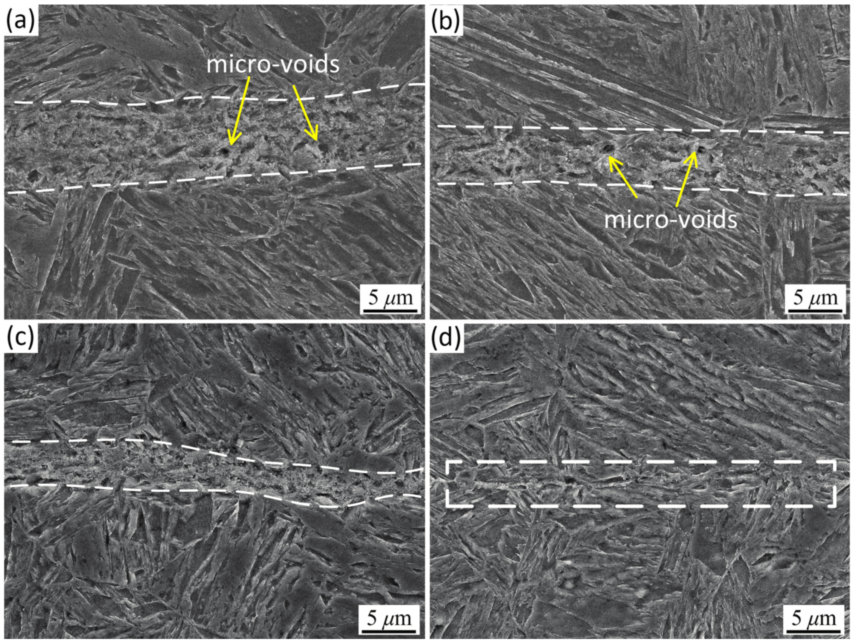
Figure 6 presents the representative SEM micrographs of crack healing zone at 1200 °C for different holding times. Figure 6a exhibits that the microstructure of crack healing zone for 5 min of holding time, with blurred dividing lines, has not yet homogenized. In addition, some micro-voids formed along the middle dividing line of the crack healing zone. Holding for 15 min, the degree of crack healing improved significantly, as shown in Figure 6b. Meanwhile, the microstructure markedly homogenized and the micro-voids also decreased in number and size. However, the meeting line in the center of the pre-crack zone mentioned above still existed. It was noted that the healing degree at 1200 °C for 5 min, as shown in Figure 6a, was apparently higher than that at 1100 °C for 60 min, as shown in Figure 2c. It suggested that healing temperatures played a more significant role in crack healing treatment. As shown in Figure 6c, when the holding time further increased to 30 min, the microstructure closely homogenized and the micro-voids were not observed, while the meeting line still remained in the center of the pre-crack. Holding for 60 min, the straight meeting line became curved and the grain-boundary triple junctions formed. This implied that the straight meeting line might transform into the grain boundary owned by the grains of the both sides and atoms in the meeting line might lay in the crystal structures of both sides.
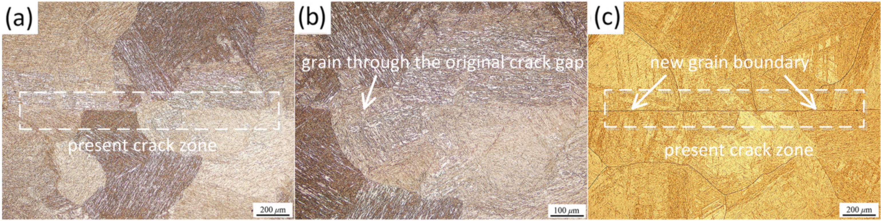
The center meeting line of the crack healing zone at 1200 °C for 60 min was observed under an OLYMPUS-BX51M optical microscope and the optical micrographs are shown in Figure 7. The microstructure of the present crack healing zone was indistinct from the matrix, as shown in Figure 7a,b. This suggests that the pre-crack had been healed completely. Figure 7b also reveals that some newly-formed grains grew through the original pre-crack gap. Figure 7c presents the grain boundaries etched by picric acid-saturated water solution. It is clearly seen that the etch depth of the center meeting line was almost identical to the grain boundary depth of the matrix.
Based on the above analysis, it can be concluded that the center meeting line is the new grain boundary. With increasing holding time, parts of the new grain boundary curved into grain-boundary triple junctions so as to balance the grain boundary energy at the triple points, indicating that the healing degree progressively increased.
Figure 8 and Figure 9 show the microstructural evolution and grain sizes of the matrix, respectively, at 1200 °C for different holding times. At 1200 °C, the grains of the matrix rapidly grew and coarsened with the increase of the holding time. As shown in Figure 9, for holding time of 5 min, the average grain size of the matrix was 176.64 μm, closely approximate to that of the sample healed at 1100 °C for 60 min (Figure 5). When the holding time increased to 30 min, the grain size dramatically increased to approximately 550 μm. Such grain coarsening severely deteriorates the mechanical properties of the material. It is well-known that the heating and cooling of large, heavy forgings are extremely slow. Healing at 1200 °C will lead to serious grain coarsening and associated mechanical property deterioration. Therefore, the internal crack healing for large, heavy forgings should be conducted at less than 1200 °C.
3.4. Influence of the Reduction Ratio
Figure 10 shows SEM micrographs of crack healing zone at 1000 °C under various reduction ratios with the strain rate of 0.1 s−1. With increasing reduction ratio, the width of the crack healing zone considerably decreased, as shown in Figure 10. The fine grain microstructures were found in the crack healing zones, indicating that recrystallized grains formed at high nucleation rates in the crack healing zones during the hot plastic deformation. Under the reduction ratios of 5% and 10%, respectively, there were still some micro-voids in the crack healing zones, as shown in Figure 10a,b. When the reduction ratio further increased up to 20%, the grains in the crack healing zone were finer. However, when the sample was subjected to a 30% height reduction, the microstructure of the crack healing zone was still inhomogeneous.
3.5. Influence of the Strain Rate
Figure 11 shows SEM micrographs of the crack healing zones at 1000 °C under 10% reduction ratio with various strain rates. It was clearly seen that the microstructural difference between the crack healing zone and the matrix still existed at the strain rates of 1 s−1 and 0.01 s−1. At the strain rate of 1 s−1, the crack healing zone was uneven, small grains produced in the crack healing zone and some micro-voids formed as well. When strain rate was decreased to 0.01 s−1, the grain size in the healing zone increased and the crack healing zone widened, the width of crack healing zone increased, as shown in Figure 11b. It is easily understood that, at high temperature where thermally-activated restoration process occurred during deformation, the microstructure depended on the strain rate, in addition to the strain. At a high strain rate, the strain energy can be stored for a short time, leading to a high driving force for recrystallization. As a result, the fine grains formed. When the strain rate decreased, it took a relatively long time to reach the intended strain. During the slow hot plastic deformation, dynamic recovery occurred, reducing the stored energy remaining to be used for the recrystallization. As a result, nucleation of the recrystallization lowered and the large grains formed. Meanwhile, slow hot plastic deformation allowed more time for grain growth and elimination of micro-voids via diffusion, consequently, widening and homogenizing the crack healing zone.
Based on the above analysis, the microstructural difference between the crack healing zone and the matrix always existed under any healing parameters after hot plastic deformation. Consequently, when internal crack healing is conducted using a hot deformation method, workpieces should continue to be heated at higher temperature for a period of time after hot deformation to promote microstructure homogenization.
3.6. Influence of Hot Pressure
A previous study [17] obtained that the yield strength of 30Cr2Ni4MoV steel at 1200 °C is approximate 40 MPa. Therefore, the samples, loaded up to 6 MPa, are still in the high-temperature elastic zone of the experimental steel. Figure 11 shows typical SEM micrographs of the crack healing zones at 1000 °C under two pressures of 2 and 6 MPa for 30 min. Compared to the healing zone obtained at 1000 °C for 60 min without the pressure, as shown in Figure 2a, the degree of the pre-crack healing in the samples at 1000 °C for 30 min under the pressures of 2 and 6 MPa significantly increased, as indicated in Figure 12. As may be seen in Figure 12a, under the pressure of 2 MPa, the width of the crack healing zone considerably decreased and the micro-voids were eliminated. This suggests that the hot pressure in the high-temperature elastic zone promoted the rapid crack healing, shortened the crack healing time, and played a more significant role in internal crack healing than the holding time. When the pressure increased to 6 MPa, the crack healing zone was homogenized and the healed interface (the central dividing line) turned into a new grain boundary, as shown in Figure 12b. Therefore, for formed heavy forgings and workpieces, hot pressure, in the high-temperature elastic zone and perpendicular to the internal crack faces, can be used to promote rapid crack healing.
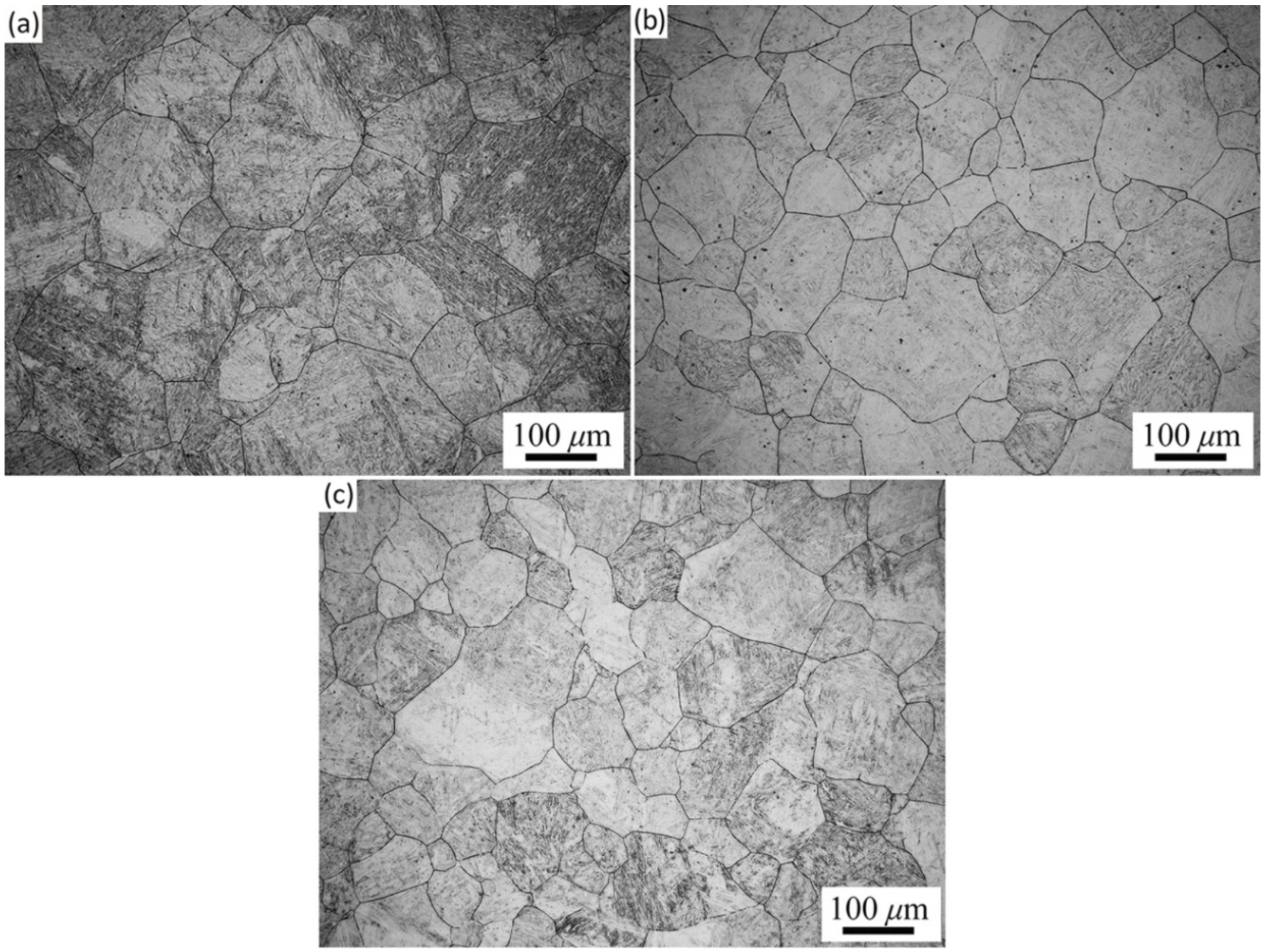
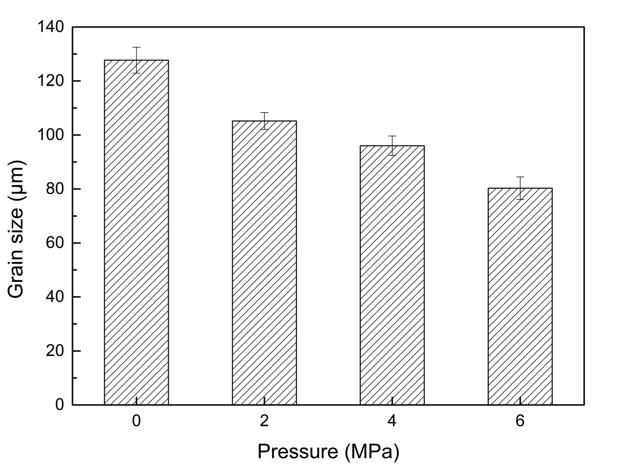
Figure 13 and Figure 14 show the microstructures and grain sizes of the matrix at 1000 °C under various hot pressures for 30 min. It is noted that the grain size of the matrix gradually decreased with the increase in pressure. Though the pressure was in the high-temperature elastic zone and relatively smaller, it still effectively prevented the grains of the matrix from coarsening during crack healing at elevated temperatures.
4. Conclusions
The conclusions which can be drawn from this study are as follows:
- The crack healing degree increased with increasing healing temperature, holding time, reduction ratio, and hot pressure, and with decreasing strain rate. To avoid grain coarsening of the matrix, the internal crack healing in large, heavy forgings of 30Cr2Ni4MoV steel should be conducted at less than 1200 °C.
- During the microstructure homogenization, an interesting phenomenon was discovered: a new grain boundary generated at the center of the crack healing zone along the direction of the pre-crack. With increasing holding time, some parts of the new grain boundary became curved and turned into grain-boundary triple junctions, and several grains grew up across the original pre-crack gap.
- When the internal crack healing was conducted using the hot deformation method, workpieces should continue to be heated at higher temperatures for a period of time after hot deformation to promote the microstructure homogenization.
- Hot pressure in the high-temperature elastic zone of the materials not only promoted the rapid crack filling but also prevented the grains of the matrix from coarsening during the crack healing at elevated temperatures. The new method of hot pressure in the high-temperature elastic zone can be used for internal crack healing, and the compressive loads should be applied normal to the internal crack faces.
Acknowledgments
The authors gratefully acknowledge financial support from the National Basic Research Program of China (2011CB012903).
Author Contributions
Ruishan Xin conceived, deigned, and performed the experiments. Ruishan Xin analyzed the data and wrote the paper. Jianbin Luo and Qingxian Ma contributed with advice on the method of analysis.
Conflicts of Interest
The authors declare no conflict of interest.
References
- Chen, M.L.; Lin, Y.C.; Chen, K.H. Evolution of elliptic-cylindrical and circular-cylindrical voids inside power viscous solids. Int. J. Plast. 2014, 53, 206–227. [Google Scholar] [CrossRef]
- Smith, W.F.; Hashemi, J. Foundations of Material Science and Engineering, 5th ed.; McGraw-Hill: New York, NY, USA, 2009. [Google Scholar]
- Xin, R.S.; Ma, Q.X.; Guo, D.D.; Li, W.Q. Restoration of impact properties of internal crack healing in a low carbon steel. Mater. Sci. Eng. A 2017, 682, 433–440. [Google Scholar] [CrossRef]
- Xin, R.S.; Ma, Q.X.; Li, W.Q. Microstructure and mechanical properties of internal crack healing in a low carbon steel. Mater. Sci. Eng. A 2016, 662, 65–71. [Google Scholar] [CrossRef]
- Griffith, A.A. The phenomena of rupture and flow in solids. Philos. Trans. R. Soc. Lond. Ser. A 1920, 221, 163–198. [Google Scholar] [CrossRef]
- Tang, Y.P.; Hosoi, A.; Morita, Y.; Ju, Y. Restoration of fatigue damage in stainless steel by high-density electric current. Int. J. Fatigue 2013, 56, 69–74. [Google Scholar] [CrossRef]
- Zhang, H.L.; Sun, J. Diffusive healing of intergranular fatigue microcracks in iron during annealing. Mater. Sci. Eng. A 2004, 382, 171–180. [Google Scholar] [CrossRef]
- Yu, H.L.; Tieu, A.K.; Lu, C.; Godbole, A. Investigation of closure of internal cracks during rolling by FE model considering crack surface roughness. Int. J. Adv. Manuf. Technol. 2014, 75, 1633–1640. [Google Scholar] [CrossRef]
- Xu, G.Q.; Demkowicz, M.J. Healing of nanocrakcs by disclinations. Phys. Rev. Lett. 2013, 111, 145501. [Google Scholar] [CrossRef] [PubMed]
- Yu, H.L.; Liu, X.H.; Li, X.W. Crack healing in a low-carbon steel under hot plastic deformation. Metall. Mater. Trans. A 2014, 45, 1001–1009. [Google Scholar] [CrossRef]
- Li, Y.; Han, J.T.; Zhang, Y.J. Crack healing behavior of 12% Cr ultra-super-critical rotor steel. Adv. Mater. Res. 2011, 152–153, 248–253. [Google Scholar] [CrossRef]
- Dong, C.F.; Li, X.G.; Shen, Z.S. Study on crack healing of hydrogen attack in carbon steel by heat treatment. Corrosion 2003, 59, 401–406. [Google Scholar] [CrossRef]
- Xiao, Y.H.; Fu, M.S.; Yuan, S. Research on the inner crack healing of 45 steel by heat treatment. Heat Treat. Met. 2005, 30, 83–85. [Google Scholar]
- Zheng, X.G.; Shi, Y.N.; Lu, K. Electro-healing cracks in nickel. Mater. Sci. Eng. A 2013, 561, 52–59. [Google Scholar] [CrossRef]
- Zheng, X.G.; Shi, Y.N.; Lou, L.H. Healing process of casting pores in a Ni-based superalloy by hot isostatic pressing. J. Mater. Sci. Technol. 2015, 31, 1151–1157. [Google Scholar] [CrossRef]
- Han, J.T.; Zhao, G.; Cao, Q.X. Discovery of inner crack recovery and its structure change in 20MnMo steel. Acta Metall. Sin. 1996, 32, 723–729. [Google Scholar]
- Li, W.Q.; Ma, Q.X. Constitutive modeling for investigating the effects of friction on rheological behavior during hot deformation. Mater. Des. 2016, 97, 64–72. [Google Scholar] [CrossRef]
Figure 1.
SEM morphology of the pre-crack.
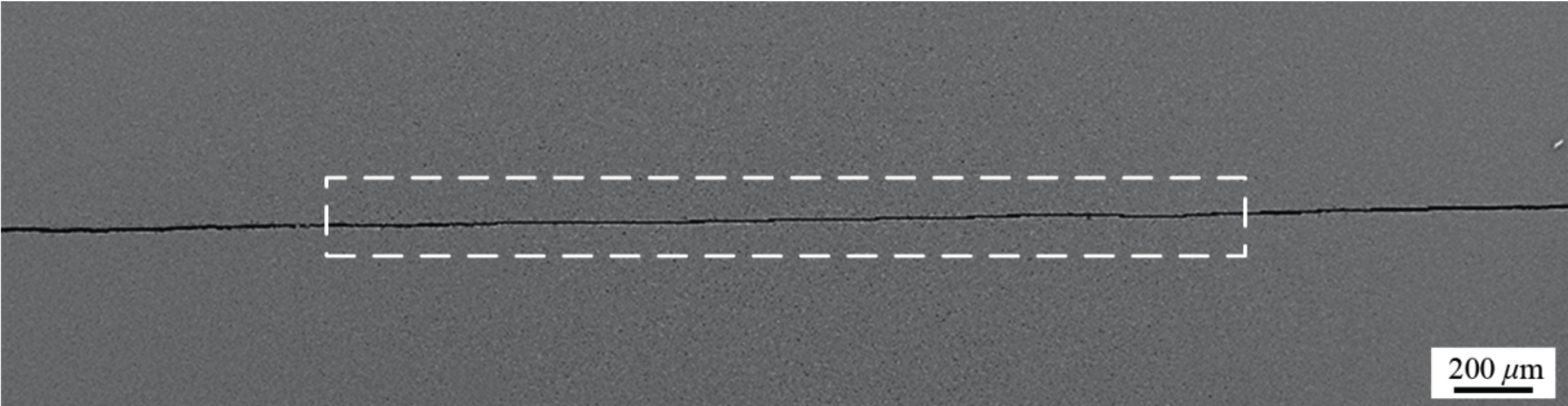
Figure 2.
SEM micrographs of crack healing zone at different healing times for 60 min: (a,b) 1000 °C; (b) magnified image of the selected region in Figure 2a showing dividing lines (yellow arrow) and recrystallized grains (black arrow); (c) 1100 °C; (d) 1200 °C.
Figure 2.
SEM micrographs of crack healing zone at different healing times for 60 min: (a,b) 1000 °C; (b) magnified image of the selected region in Figure 2a showing dividing lines (yellow arrow) and recrystallized grains (black arrow); (c) 1100 °C; (d) 1200 °C.
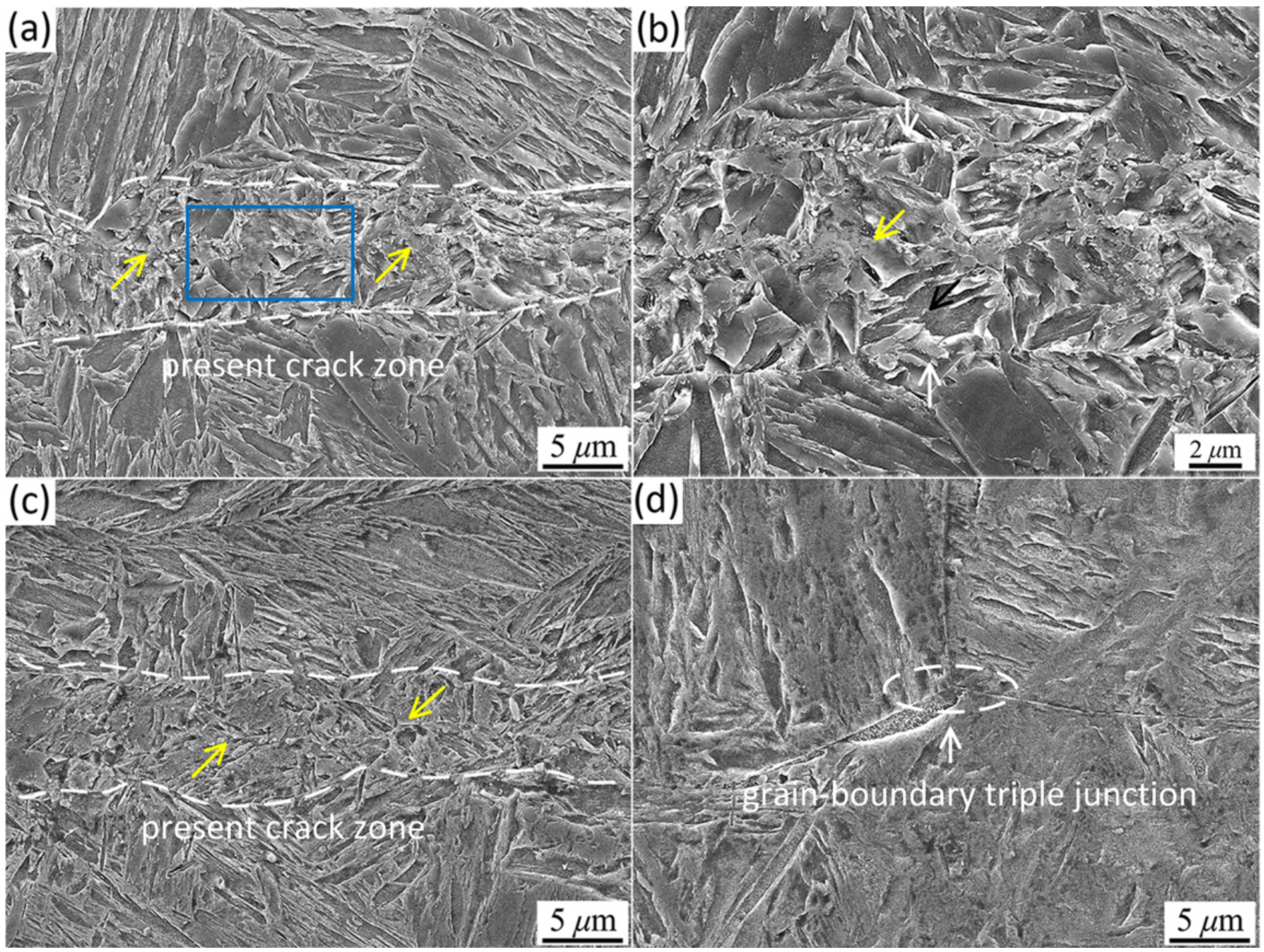
Figure 3.
OM micrographs of the crack healing zone at different healing times for 60 min: (a) 900 °C; (b) 1000 °C; (c,d) 1100 °C; and (d) the magnified image of Figure 3c showing fine recrystallized grains in the crack healing zone.
Figure 3.
OM micrographs of the crack healing zone at different healing times for 60 min: (a) 900 °C; (b) 1000 °C; (c,d) 1100 °C; and (d) the magnified image of Figure 3c showing fine recrystallized grains in the crack healing zone.

Figure 4.
Microstructural evolution of the matrix at different healing times for 60 min: (a) 900 °C; (b) 1000 °C; (c) 1100 °C; and (d) 1200 °C.
Figure 4.
Microstructural evolution of the matrix at different healing times for 60 min: (a) 900 °C; (b) 1000 °C; (c) 1100 °C; and (d) 1200 °C.
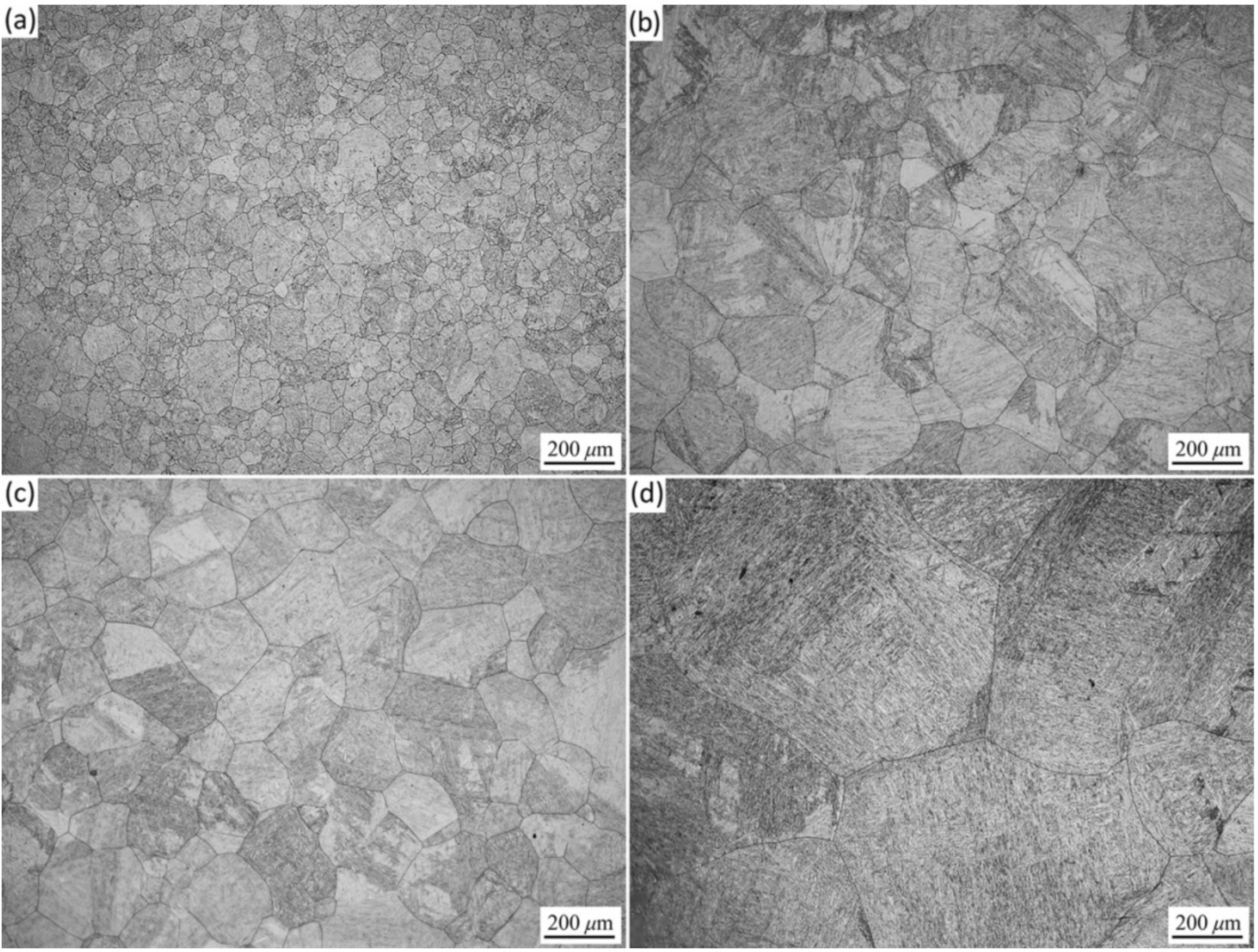
Figure 5.
Grain sizes of the matrix and crack healing zone at different healing times for 60 min.

Figure 6.
SEM micrographs of the crack healing zone at 1200 °C for different holding times: (a) 5 min; (b) 15 min; (c) 30 min; and (d) 60 min.
Figure 6.
SEM micrographs of the crack healing zone at 1200 °C for different holding times: (a) 5 min; (b) 15 min; (c) 30 min; and (d) 60 min.
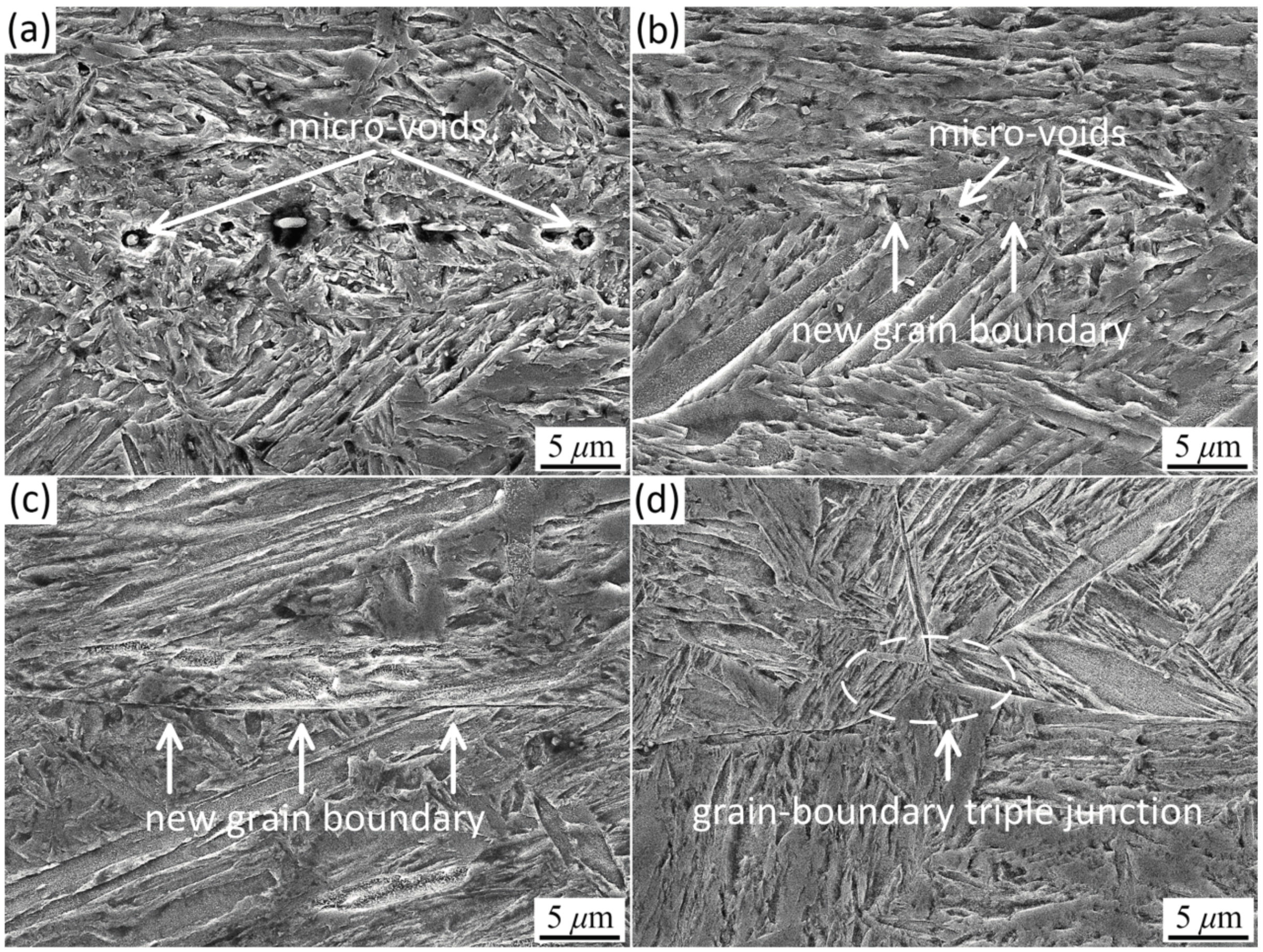
Figure 7.
Optical micrographs of the crack healing zone at 1200 °C for 60 min: (a) microstructural morphology etched in 4% nital showing the present crack zone; (b) magnified image of Figure 7a showing mutual grain; and (c) grain boundaries etched in a picric acid-saturated water solution showing the new linear mutual grain boundary.

Figure 8.
Microstructural evolution of the matrix at 1200 °C for different holding times: (a) 5 min; (b) 15 min; (c) 30 min; and (d) 60 min.
Figure 8.
Microstructural evolution of the matrix at 1200 °C for different holding times: (a) 5 min; (b) 15 min; (c) 30 min; and (d) 60 min.

Figure 9.
Grain sizes of the matrix at 1200 °C for different holding times.
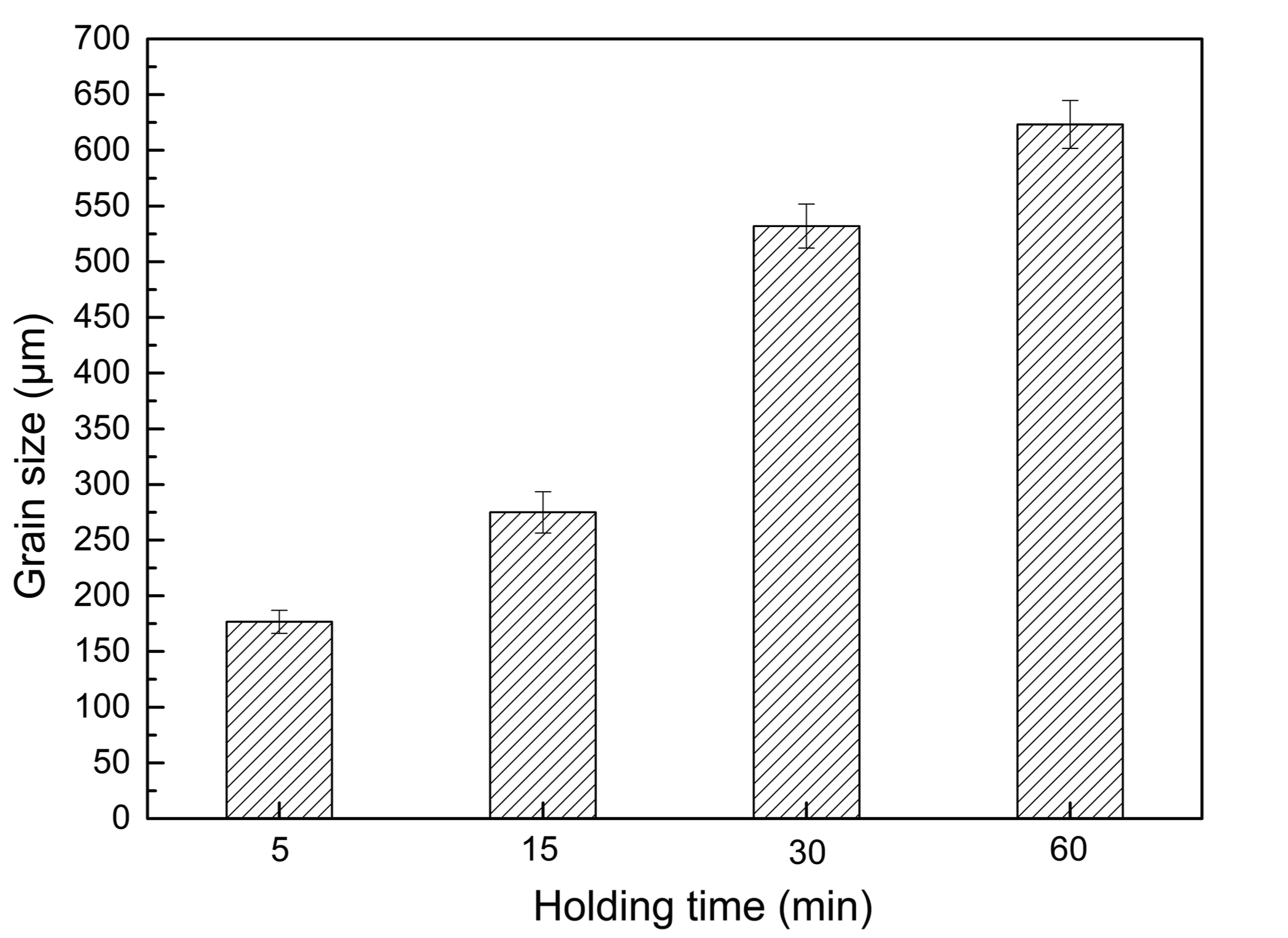
Figure 10.
SEM micrographs of crack healing zone at 1000 °C under various reduction ratios with a strain rate of 0.1 s−1: (a) 5%; (b) 10%; (c) 20%; and (d) 30%.
Figure 10.
SEM micrographs of crack healing zone at 1000 °C under various reduction ratios with a strain rate of 0.1 s−1: (a) 5%; (b) 10%; (c) 20%; and (d) 30%.

Figure 11.
SEM micrographs of crack healing zone under 10% reduction ratio at 1000 °C with different strain rates: (a) 1 s−1; and (b) 0.01 s−1.
Figure 11.
SEM micrographs of crack healing zone under 10% reduction ratio at 1000 °C with different strain rates: (a) 1 s−1; and (b) 0.01 s−1.
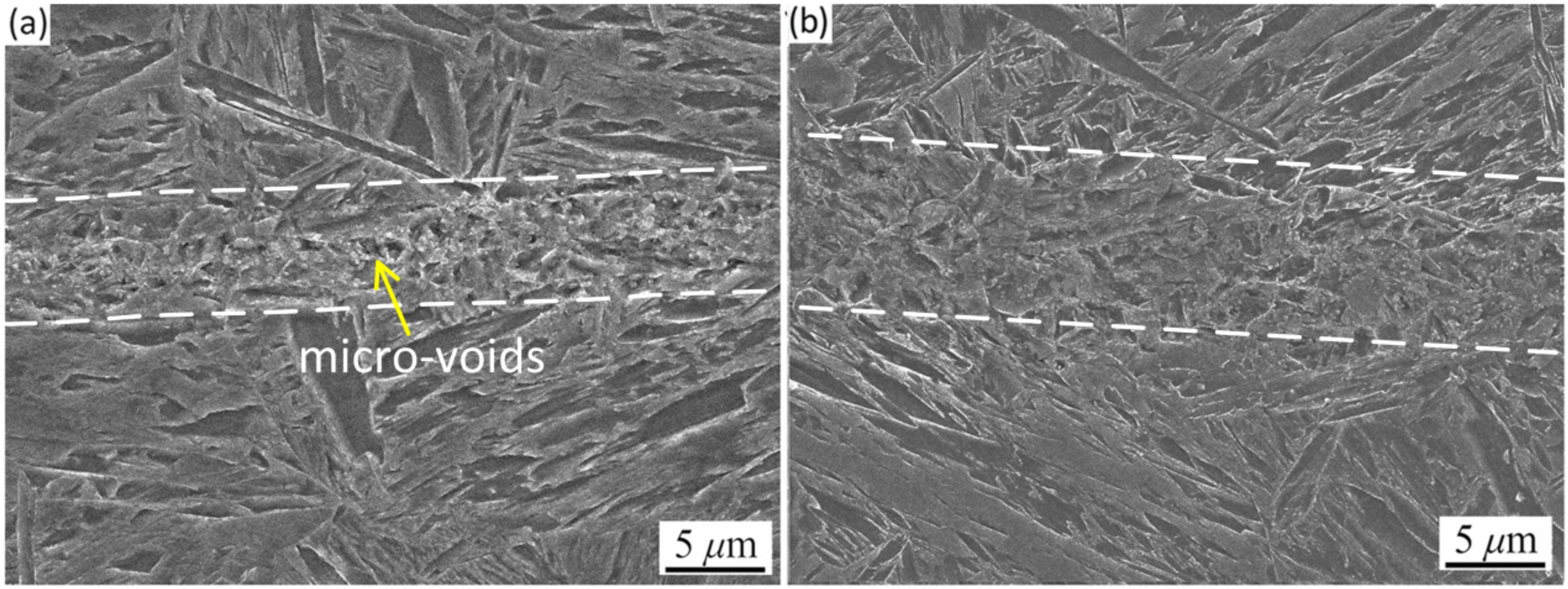
Figure 12.
SEM micrographs of crack healing zone at 1000 °C under various hot pressures for 30 min: (a) 2 MPa; and (b) 6 MPa.
Figure 12.
SEM micrographs of crack healing zone at 1000 °C under various hot pressures for 30 min: (a) 2 MPa; and (b) 6 MPa.
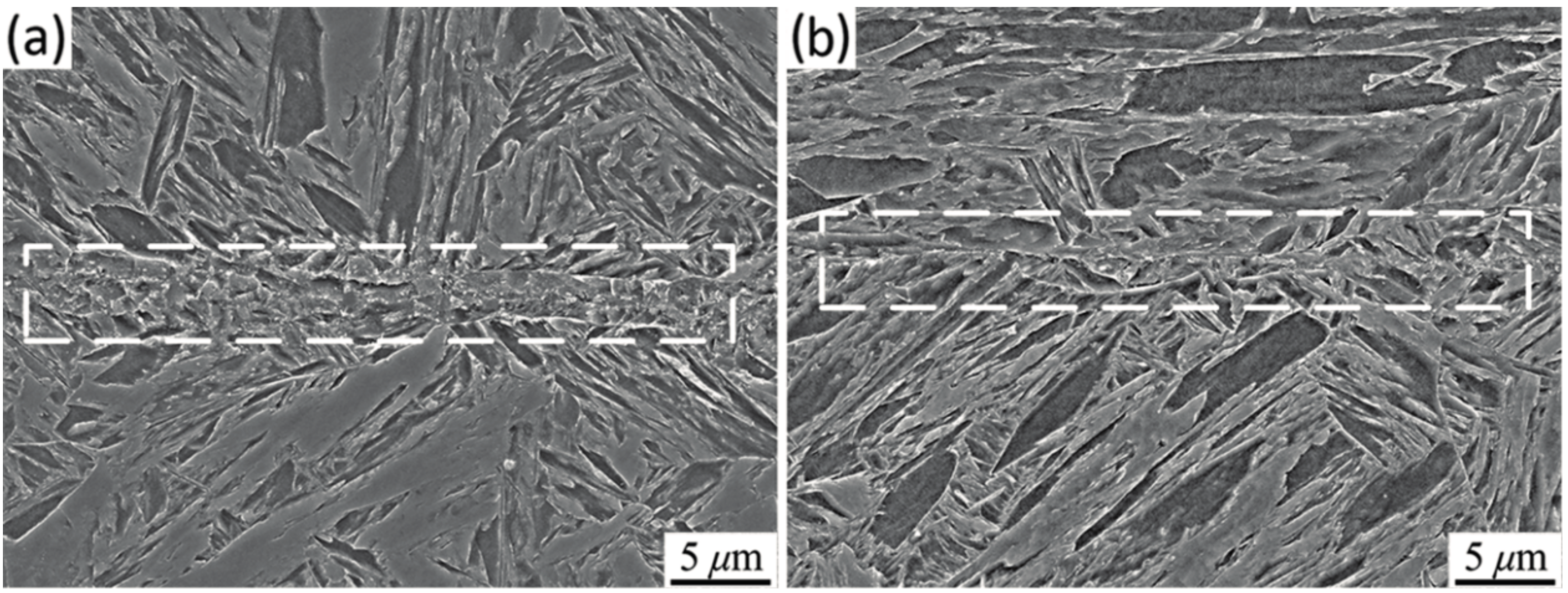
Figure 13.
Microstructural evolution of the matrix at 1000 °C under various hot pressures for 30 min: (a) 0 MPa; (b) 2 MPa; and (c) 6 MPa.
Figure 13.
Microstructural evolution of the matrix at 1000 °C under various hot pressures for 30 min: (a) 0 MPa; (b) 2 MPa; and (c) 6 MPa.

Figure 14.
Grain sizes of the matrix at 1000 °C under various hot pressures for 30 min.


Table 1.
The chemical composition of the 30Cr2Ni4MoV steel (wt %).
| C | Cr | Ni | Mo | V | Mn | Si | S | P |
|---|---|---|---|---|---|---|---|---|
| 0.24 | 1.72 | 3.65 | 0.40 | 0.093 | 0.28 | 0.03 | 0.03 | 0.005 |
© 2017 by the authors. Licensee MDPI, Basel, Switzerland. This article is an open access article distributed under the terms and conditions of the Creative Commons Attribution (CC BY) license (http://creativecommons.org/licenses/by/4.0/).
Share and Cite
MDPI and ACS Style
Xin, R.; Luo, J.; Ma, Q. Effect of Parameters on Internal Crack Healing in 30Cr2Ni4MoV Steel for 600-Ton Ultra-Super Ingots. Metals 2017, 7, 149. https://doi.org/10.3390/met7040149
AMA Style
Xin R, Luo J, Ma Q. Effect of Parameters on Internal Crack Healing in 30Cr2Ni4MoV Steel for 600-Ton Ultra-Super Ingots. Metals. 2017; 7(4):149. https://doi.org/10.3390/met7040149
Chicago/Turabian StyleXin, Ruishan, Jianbin Luo, and Qingxian Ma. 2017. "Effect of Parameters on Internal Crack Healing in 30Cr2Ni4MoV Steel for 600-Ton Ultra-Super Ingots" Metals 7, no. 4: 149. https://doi.org/10.3390/met7040149
Note that from the first issue of 2016, this journal uses article numbers instead of page numbers. See further details here.