Article

Aluminium Wires Have the Free Air Balls (FABs): Electronic Flame-Off, Fracture Strength, Electrical Properties, and Bonding Characteristics of Nano Zn Film Al–Si Bonding Wires

Department of Materials Science and Engineering, National Cheng Kung University, Tainan 701, Taiwan
*
Author to whom correspondence should be addressed.
Metals 2017, 7(5), 152; https://doi.org/10.3390/met7050152
Submission received: 18 November 2016 / Revised: 21 March 2017 / Accepted: 20 April 2017 / Published: 25 April 2017

Abstract

:
Aluminum wire is a common material for wire bonding due to its resistance to oxidation and low price. It does not melt when becoming a free air ball (FAB) during the electronic flame-off (EFO) process with wettability and is applied by wedge bonding. This study used 20 μm Zn-coated Al–0.5 wt % Si (ZAS) wires to improve the FAB shape after the EFO process, while maintaining the stability of the mechanical properties, including the interface bonding strength and hardness. In order to test circuit stability after ball bonding, the current-tensile test was performed. During the experiment, it was found that 80 nm ZAS with wire bonding had lower resistance and its fusing current was higher. For the bias tensile test, the thicker Zn film diffused into the Al–Si matrix easily, after which the strength was reduced. The ball-bond interfaces had no change in their condition before and after the bias. Accordingly, the ZAS wire could be a promising candidate for ball bonding in the future.

1. Introduction

Al wire has been used in the wire-bonding process for decades; however, the percentage is relatively low compared to gold and copper wires because of its poor FAB shape and structure [1,2,3,4]. In addition, high or low wire resistance does not affect the functioning of an integrated circuit (IC) chip when the internal resistance of the whole IC chip (on-chip) is high. In other words, regardless of whether gold wire (low resistance) or gold alloy wire (high resistance) is used, similar resistance with the same IC chip results. Every bonding wire has its resistivity [5] (Au: 2.44 × 10⁻⁸, Cu: 1.68 × 10⁻⁸, and Al: 2.82 × 10⁻⁸ Ω·m). However, after bonding, the resistances of the on-chip interconnect have almost identical resistivity. The reason is that the resistances of the bonding interfaces in the chip are high. For example, the resistance of the intermetallic compounds (IMCs) between the solder and copper pad is much higher than the resistance of the wires [6,7]. High purity Al wire has low resistance, and by adding 0.5 wt % Si, the mechanical properties can be improved without enhancing the resistance of the Al wire [8]. Melted Al oxidizes easily and results in poor ball morphology (i.e., cannot form a FAB). In this study, we coated a Zn nano-film on the surface of the Al–0.5Si wire to improve the EFO process. The reason we chose Zn is that its melting point and boiling temperature are both lower than those of Al metal, the latter of which is about 907 °C. Due to these differences, a stable Al–Si–Zn FAB matrix can be obtained because Zn can protect Al from oxidation during the EFO process [9]. Accordingly, to better characterize this material, the mechanical and electrical properties following Zn nano-film coated Al wire (ZAS) wire bonding are discussed in the present paper. Results indicate that the ZAS wire is suitable for ball bonding and that the presented EFO process could be used as a reference for packaging applications.

2. Experiment

In this study, the diameter of the employed fine Al–0.5Si wire was 20 µm, and was coated with a Zn nano film by a chemical plating method, called electroless plating. The chemical plating solution included ZnO, NaOH, KNaC4H4O6·4H2O, and water. Two coating thicknesses of the Zn thin film were obtained, namely 80 nm (ZAS80) and 250 nm (ZAS250), as shown in Figure 1. In comparison, the ZAS wire did not show any significant change on the surface.
A free air ball (FAB) was formed by the electronic flame-off (EFO) process with a wire-bonding machine (55 mA, 15 ms), the first FAB bond of which was on 800 nm aluminum pads [10,11]. To prevent oxidation, a 95% nitrogen–5% hydrogen gas mixture was used during the EFO process. Morphology and cross-section analyses were performed by FIB-SEM (FEI Nova-200, Hillsboro, OR, USA). An electron probe X-ray micro-analyzer (EPMA, JEOL JXA-8900R, Peabody, MA, USA) was used to observe the element distribution in the Al–0.5Si wire. The hardness from the FAB to the wire was investigated by micro-hardness (HK) tester (Mitutoyo HM-220A, Aurora, IL, USA), for which the loading force and holding time were 98 mN and 10 s, respectively. The pull test of the first bond was performed with a test length of 50 mm, yielding a strain rate of 5 × 10⁻³ s−1. Moreover, to better understand the differences between the Al–0.5Si and ZAS wires, current tests of the first bond (FAB) were compared [12,13,14,15,16], and a bias tensile test of the wires with different currents was performed. The schematic diagram in Figure 2 shows that, for the current test, the effective wire length was 30 mm, and the applied DC voltage increased at 0.05 V/s from 0 V until the wire fused. In addition, the second bond specimens were compared before and after 48 h of aging in a vacuum. All data are the average of 10–12 experimental repetitions.

3. Results and Discussion

After the EFO process, the Al–0.5Si wire had serious oxidation, while the ZAS wire had better FABs. Figure 3 shows the FIB-SEM images of the FABs from the two ZAS wires, including surface morphology and the cross section. As can be seen, different Zn film thicknesses apparently affected the FAB morphology, the degree of surface roughness, and the cross-sectional structure.
The FAB surface and cross-section images of the ZAS80, which were cut vertically, are shown in Figure 3a,b, respectively. The image shows that the morphology of ZAS80 FAB is a circle, and that Zn apparently improves the shape of the Al–0.5Si FAB. Due to the lower Gibb’s free energy of ZnO, the formation of Al2O3 is hindered, resulting in a better FAB shape (Figure 3a) [9]. The dark spots on the surface of the FAB are pollutants. After the EFO process, observations of the FAB surface were performed immediately before more pollutants (induced air sulfide) had time to form on the surface. Further, micro-pores formed randomly due to the strong oxidation–reduction reaction and are visible in the FAB cross section (Figure 3b). This means that gas in the melting Al–0.5Si FAB could not be fully exhausted with the 80 nm Zn coating on the surface [17]. Notably, previous research regarding powder sintering also found that zinc particles easily formed pores in liquid pools [18], as with our results. In order to improve this, we increased the thickness of the Zn film to 250 nm (ZAS250), the morphology of which is shown in Figure 3c. As seen, although the ZAS250 FAB surface was rough due to the strong oxidation–reduction reaction, there were no pores visible in the cross-section image (Figure 3d). This suggests that, although a sufficient zinc content had an exhaust effect for the FAB, the thicker zinc coating caused a rougher ball surface. The main reason is that Zn can protect Al from oxidation and lower the melting point during the EFO process. If the thickness is less than 80 nm, we cannot obtain the FAB of wire. When the thickness is more than 250 nm, the surface of the FAB is rougher.
The element distribution of ZAS250 after the EFO process is shown in Figure 4. During EPMA analysis, the long scanning time on the ball zone caused some deformation in the ball portion. In fact, the as-received wire was an aluminum wire containing 0.5 wt % Si, so there were some Si signals in the wire. A trace Zn signal was detected from the FAB to the heat-affected zone (HAZ: un-melted and solid-state surface reaction only); however, the signal became clear 100 μm away from the FAB. The boiling point of Zn is 907 °C, but the temperature of the EFO process is much higher; accordingly, Zn in the FAB and the heat-affected zone (HAZ) volatilized easily during the EFO process. In addition, adding Zn into the Al matrix can lower the alloy’s melting point. As such, the gas in the ZAS250 FAB readily exhausted and caused a rougher FAB surface morphology. After the EFO process, we found that (1) Al wire without a Zn coating cannot form a FAB; (2) with an 80 nm Zn coating, the ball surface was smooth but had pores inside the ball; (3) with a 250 nm Zn coating, the surface was rough, but the ball had no pores.
The micro-hardness and tensile properties of the ZAS80 wire after the EFO process are shown in Figure 5, which reveals that the neck of the FAB was the weakest. The hardness of the FAB center and the wire were about the same (Figure 5a). This phenomenon can be attributed to the coarse grains (heat energy from EFO process) in the neck of the FAB (HAZ area), which caused the low hardness [19,20]. After bonding on the Al pads, the breaking load of the ZAS80 and ZAS250 wires were found to both be about the same at 35.38–35.67 mN, as presented in Figure 5b (an image of the first bond is shown). This implies that neither the thickness of the Zn film nor the pores in the ZAS80 FAB had any effect on the bonding strength of the wires. Notably, the coated Zn film of Al–0.5Si wire for EFO did cause some effects in the FAB and HAZ: (1) the FAB had a lower melting point (re-melting and then solidification), increased wettability (reduction reaction and form a ball), and easy gas exhaustion; (2) the HAZ (near the neck zone) featured un-melted solid-state surface reactions only. The coated Zn film vaporized, so no Zn signal was detected on the wire’s surface.
ZAS wires used in wire bonding with ball bonding is an important innovation in packaging; consequently, investigating the electrical properties after wire bonding is necessary. The original wire (AS) without the coated Zn film could not achieve a good shape, so the current test with the wedge-bonding process was necessary. The experimental data for the fusing currents of the Al–0.5Si, ZAS80, and ZAS250 wires are shown in Figure 6. As can be seen, the I–V curves indicate that the three wires were all linear under 0.20 A (Zone I); however, resistances of the Zn-coated wires were reduced due to the oxidation prevention of the Zn film on the surface. When the current exceeded 0.20 A (Zone II), the wires’ resistances greatly increased due to the Joule effect of thermoelectricity (the resistance increases as the temperature increases). The resistances increased rapidly in tandem with the increasing current until fusing. The Al–0.5Si wire (not Zn coated) with wedge bonding had the highest fusing current of almost 0.3 A, while the fusing currents of the ZAS80 and ZAS250 were 0.28 A and 0.26 A, respectively. With the thinner Zn film (high purity), the ZAS80 wire had a lower resistance than the ZAS250; however, the latter had a lower fusing current due to the melting point being reduced by the higher Zn content. Notably, the pores in the ZAS80 FAB did not apparently influence the resistivity. Al metal has a high ductile property, but its FAB is a rapidly solidified structure with lower toughness. It was noted that the porous FAB of the ZAS80 wire had good ductility and toughness (sponge-like) for wire bonding [21,22]. After bonding, the ZAS80 FABs processed a uniform deformation behavior. Accordingly, it is clear that a porous ball bond did not influence the stress concentration to reduce the interface strength.
Figure 7 shows the bias tensile properties of the three wires with different currents. The AS wire and ZAS80 wire featured bias tensile strength of more than 88.2 mN (9 gf) in 0.15 A, but that of the ZAS250 wire was lower. The elongation of three wires was reduced after the bias tensile test (For example: As-received wire: AS = 2.24%; AS wire for the 0.15 A test: AS 0.15 A = 1.72%; AS wire for the 0.20 A test: AS 0.20 A = 1.45%). The current effect caused the strength and elongation of the wires to decrease. The main reason is that the thicker Zn film easily diffused into the Al–Si matrix under the Joule effect (from the surface into the core, thereby affecting the dispersion strengthening of Si), which reduced the strength. When increasing the current to more than 0.2 A, the strength of the wires was decreased under the bias-tensile test.
In Figure 8 and Figure 9, the bonding interfaces of the ZAS80 were observed before and after bias (60% fusing current for 24 h). As shown, their interfaces are flat and no IMC formed. Consequently, it is clear that the interface resistance of ZAS80 is stable, and that the Al wire ball bonds on the Al pad possess good reliability.
After 48 h vacuum aging, the second bonds of the AS and ZAS80 wire were compared. This study used the nozzle of a gold-wire machine to perform the second bonding, for which all specimens used the same bonding conditions. There are two reasons for this direct comparison: (1) to investigate whether the Zn coating can improve the bond-strength before heat aging, and (2) to check if the bond-interface peeled after heat aging. Due to the Al pad being a sputtered film and processes an obvious indentation. It was found that the appearance of the AS wire was similar before and after aging (Figure 10). Notably, the second bonds of the ZAS80 wire not only had good aging resistance (Figure 11), but also higher average pull-strength (the second bond strength, ZAS80 = 52.136 mN (5.32 gf), AS = 49.784 mN (5.08 gf)). Figure 10 and Figure 11 present images of the second bond of the ball-bonding machine for the Al wire. In addition, the annealed Al pad is softer and causes a deeper indentation. Without pressing deeper, the ball-bond nozzle cannot smoothly cut off the Al wire. The ZAS80 wire has an excellent second bonding characteristic. After 48 h vacuum aging, there is no significant degradation on the surface of second bonds.
In this system (Figure 12), the ZAS80 wire is found to be highly reliable for wire bonding. With a Zn coating, the ball surface is smooth and contains some pores inside the ball. By the pull test and the current test, the interface strength and interface resistance of ZAS wire is stable. In future studies, the bonding interface and aging characteristics for Al wire application will be investigated.

4. Discussion

(1)
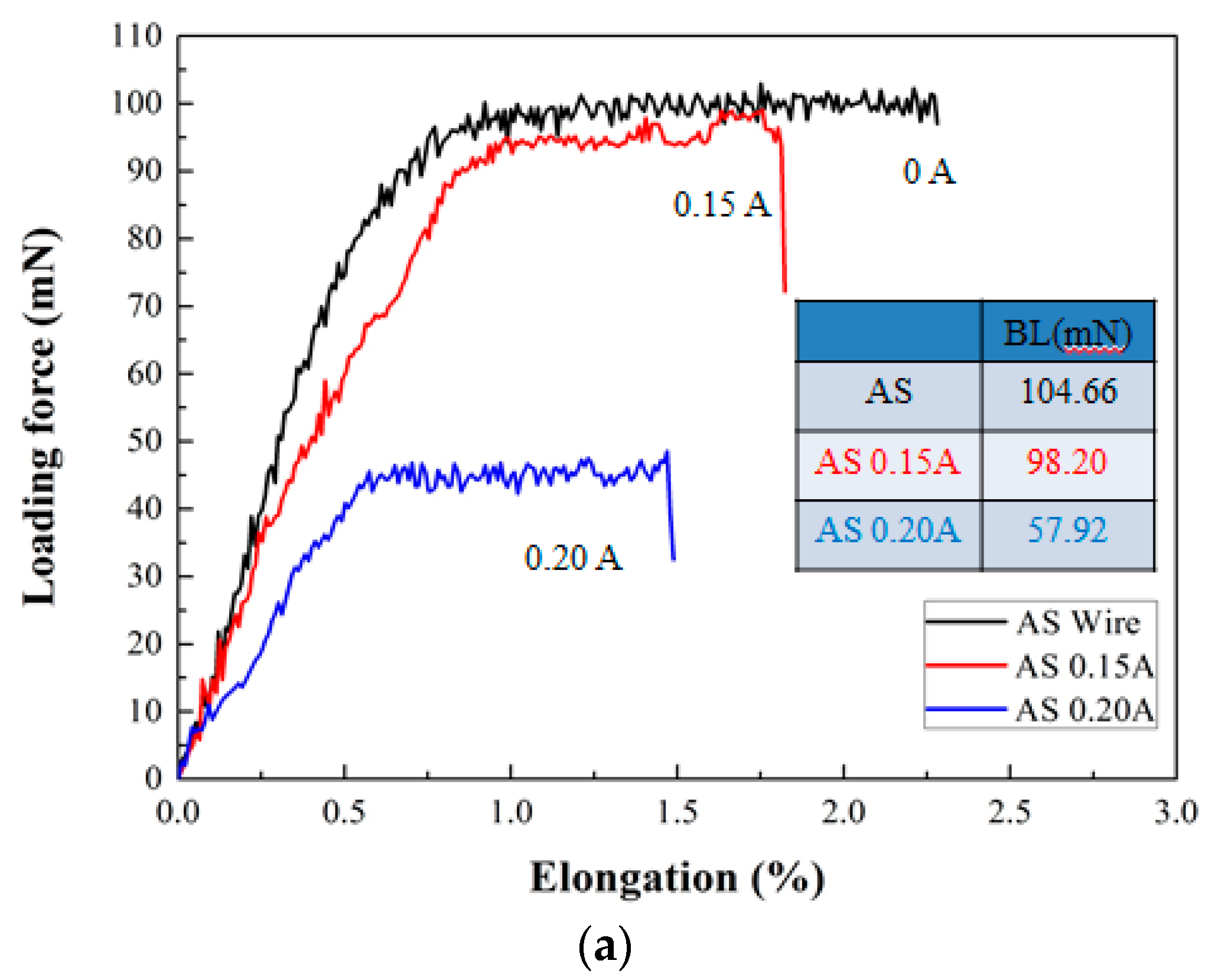
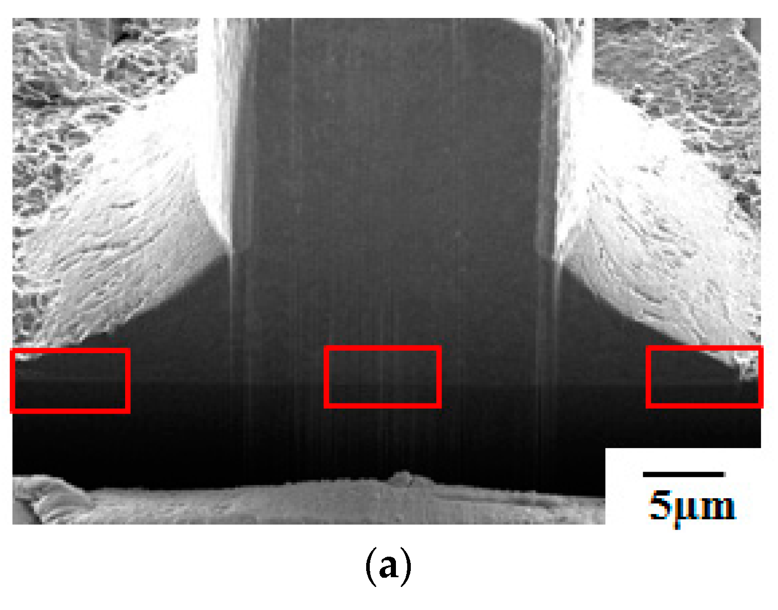
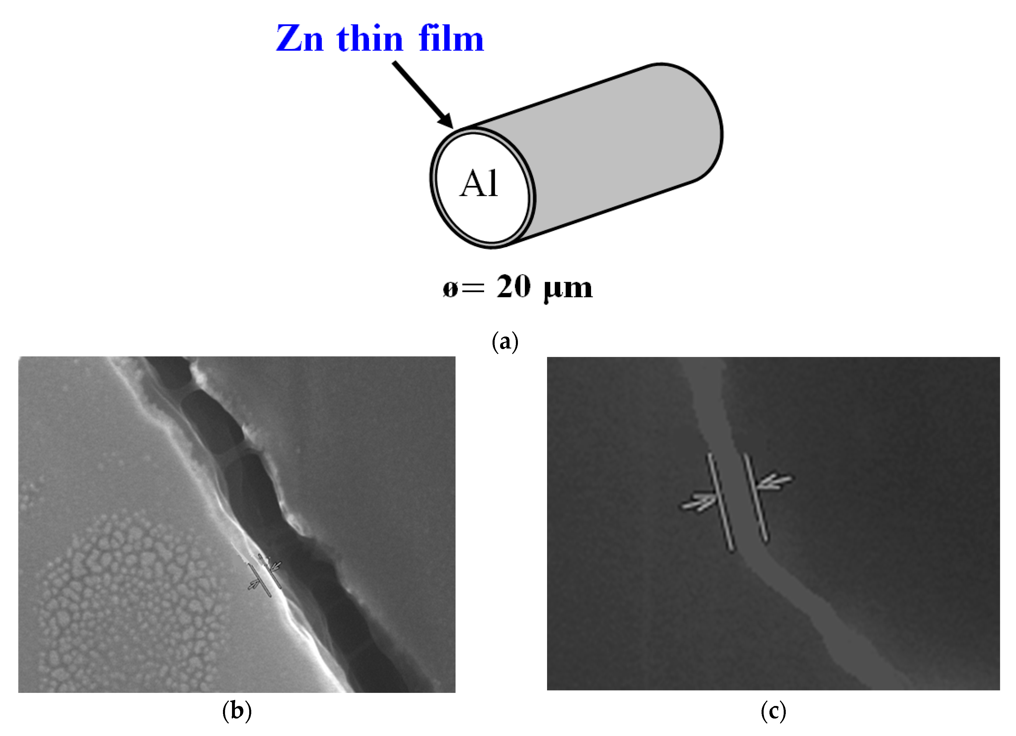
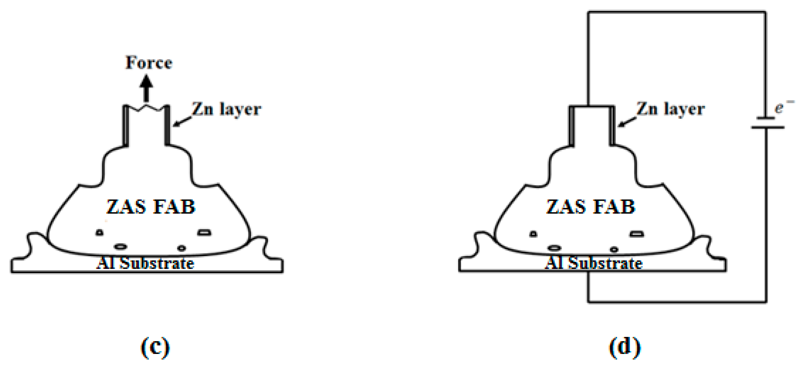
Currently, Al wires cannot be used in wire bonding with ball bonding; however, coating Al–0.5 wt % Si wire with a Zn film with 80–250 nm can improve this problem. Further, the mechanical properties, bonding strengths and bias tensile strength of the 20 μm Zn-coated Al–0.5 wt % Si (ZAS) wires are stable.
(2)
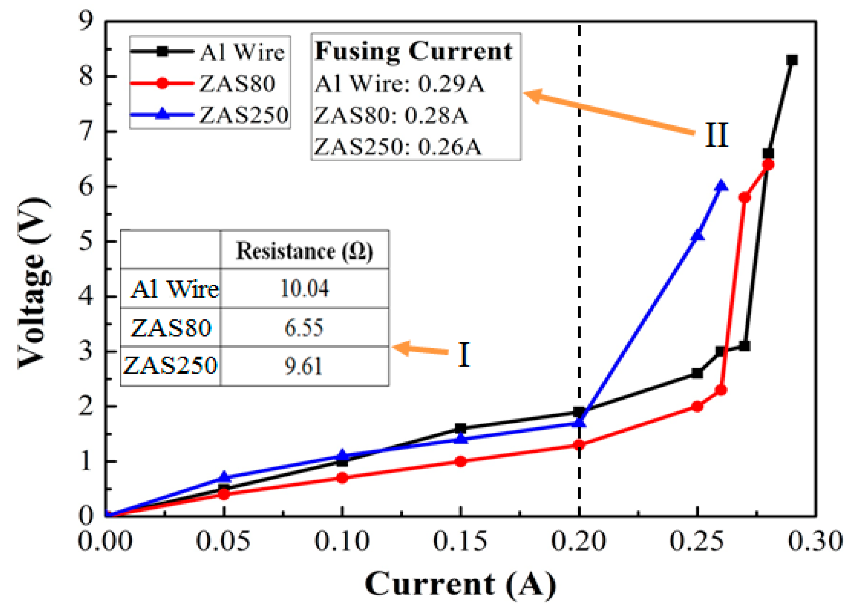
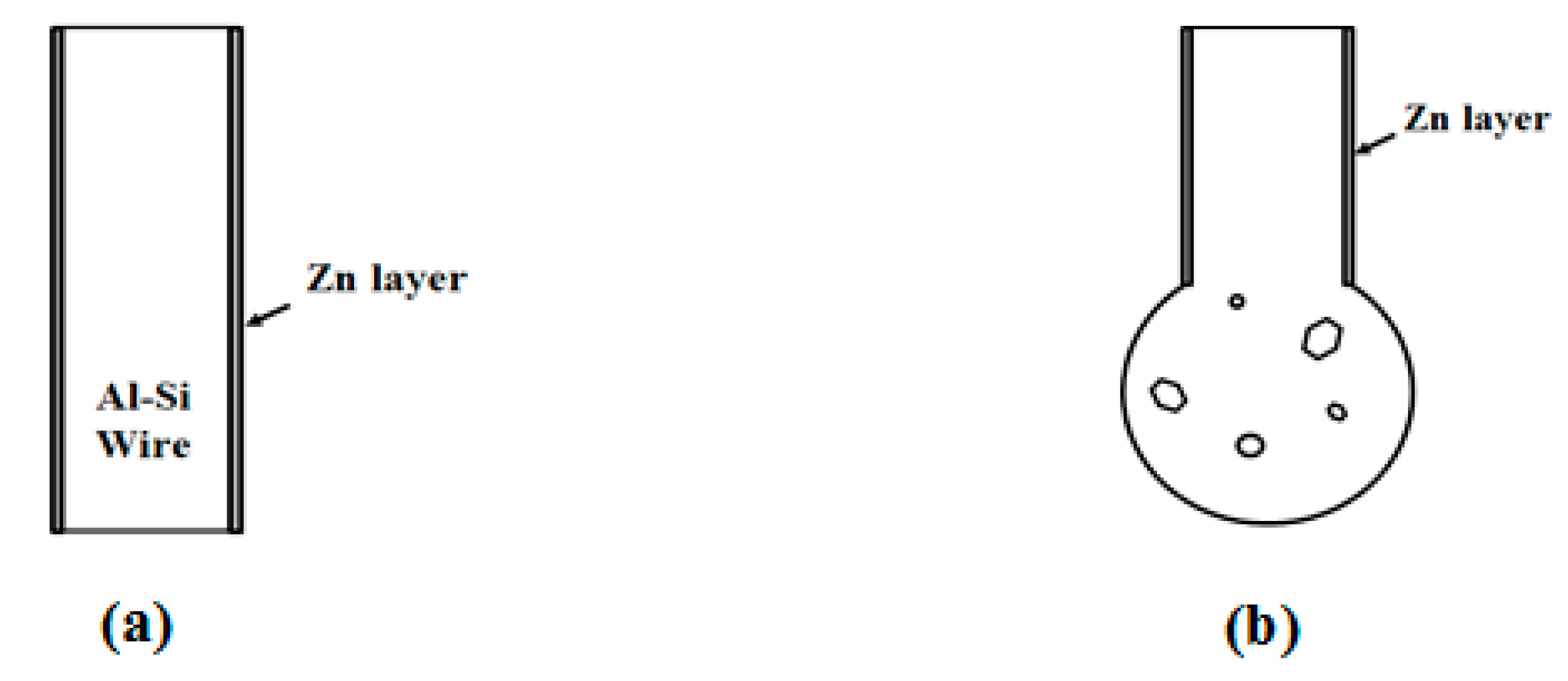
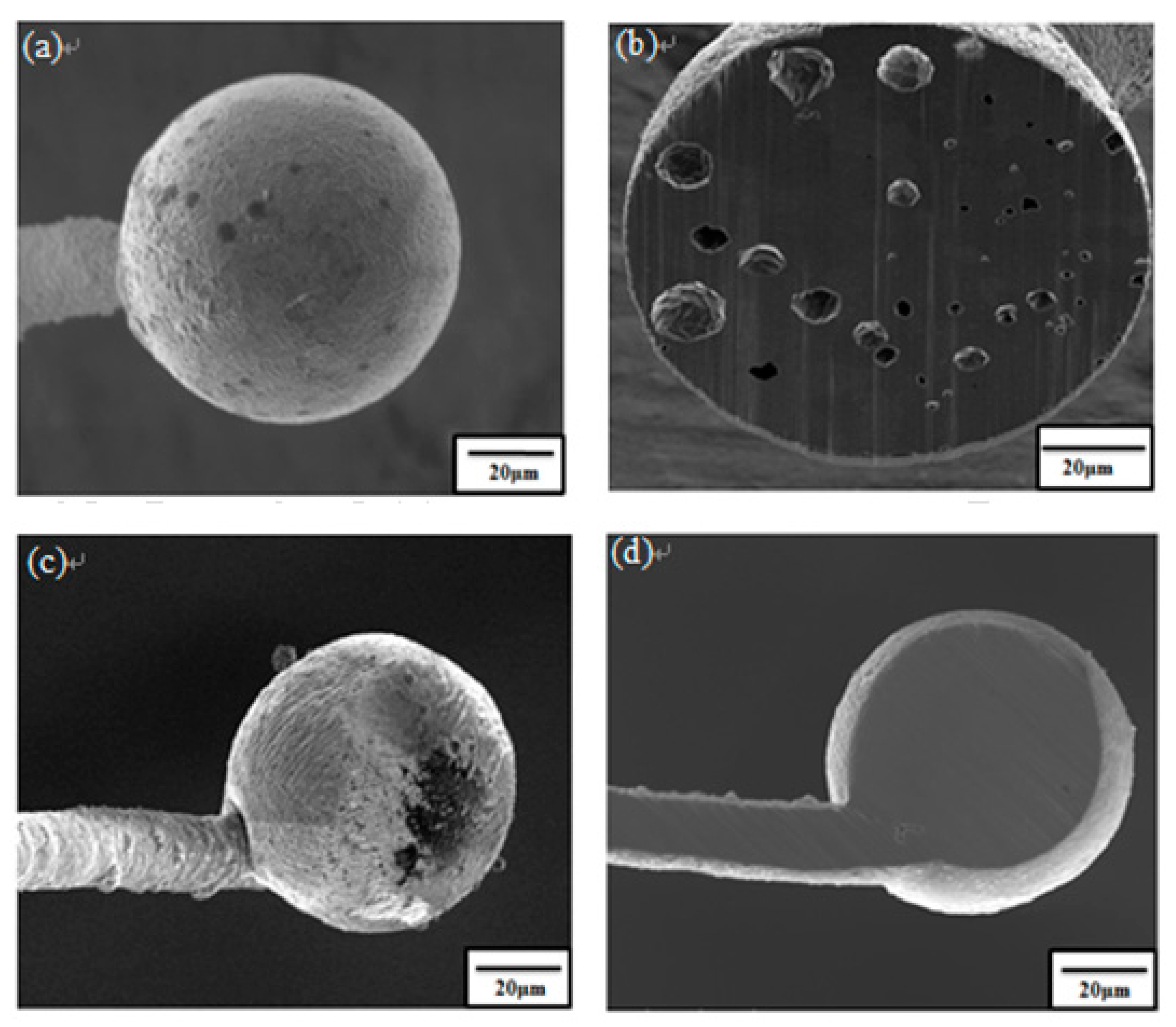
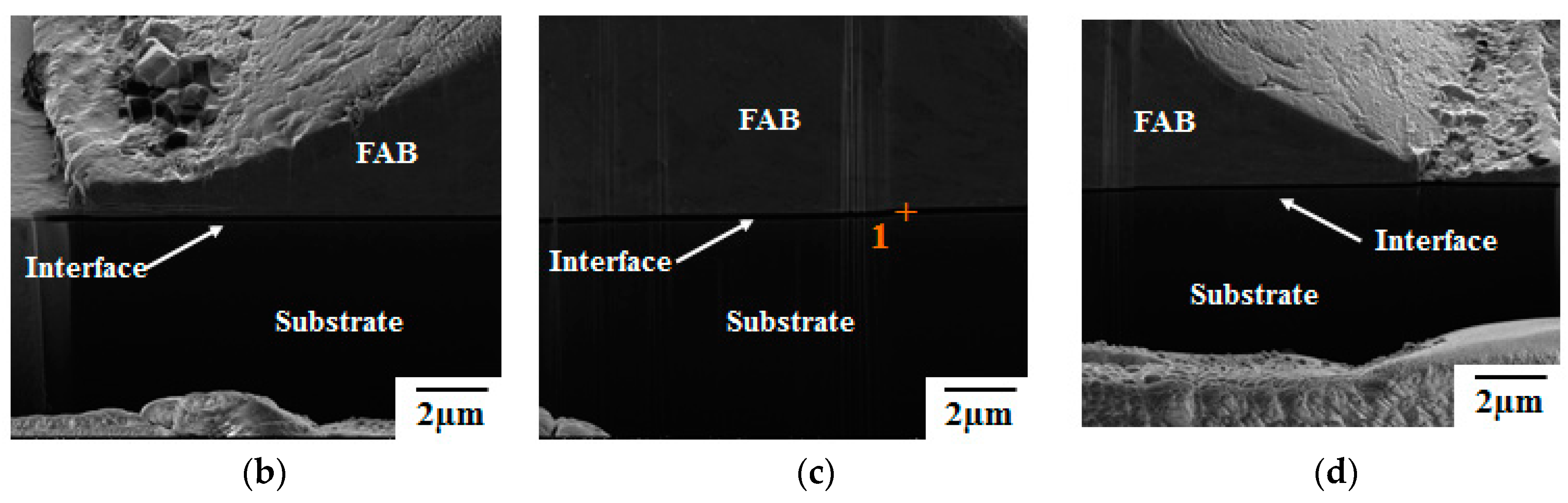
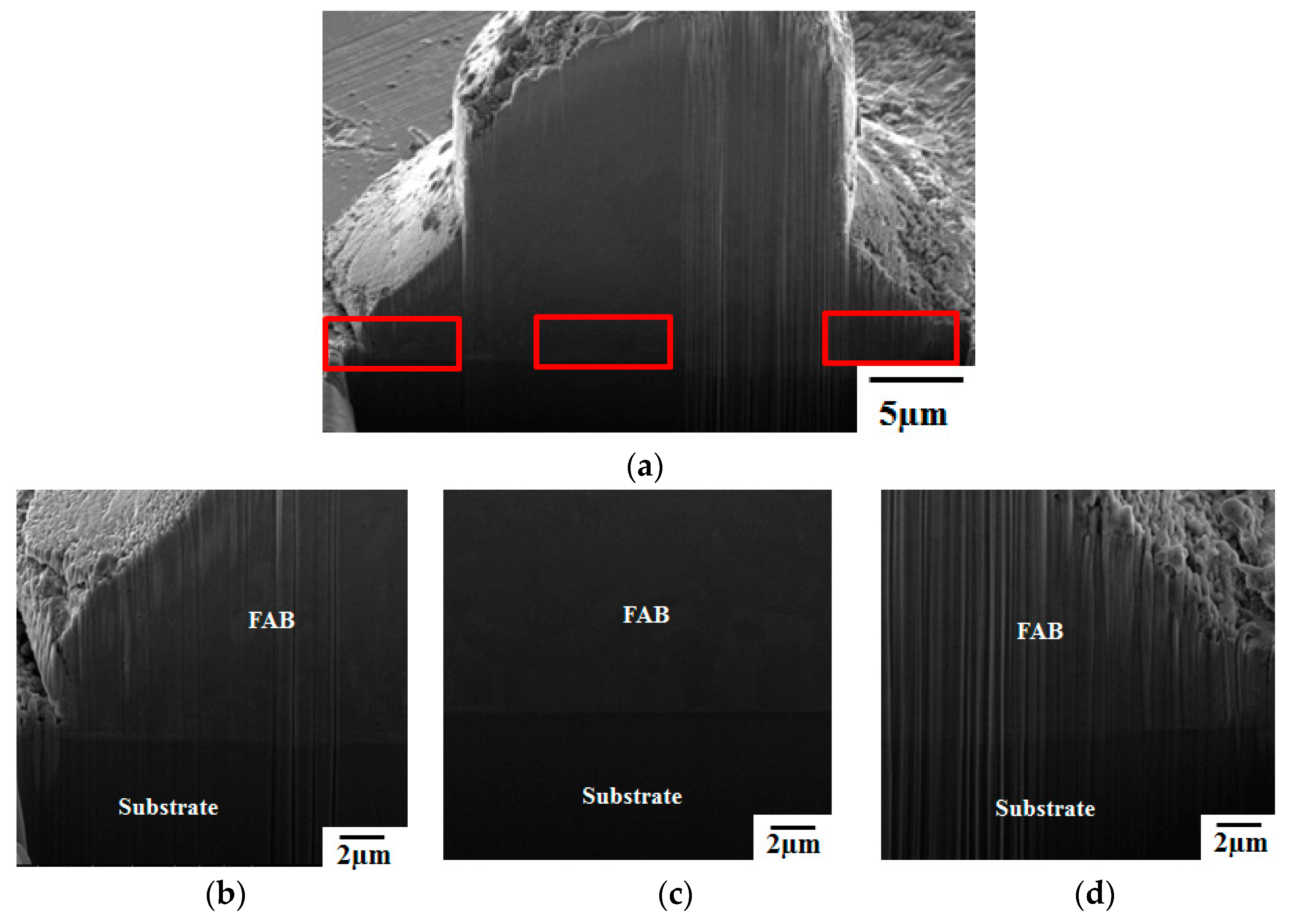
Pores in the 80 nm ZAS wire FAB have no influence on bonding characteristics. Moreover, the low interface resistance, high fusing current, and excellent aging surface of the 80 nm ZAS wire hold potential for application in IC packaging.

Acknowledgments

The authors are grateful to the Instrument Center of National Cheng Kung University and the National Science Council of Taiwan (MOST 105-2628-E-006-001-MY2) for their financial support.

Author Contributions

Fei-Yi Hung is to study the design and writing article. Truan-Sheng Lui assists the preparation of materials. Kuan-Ming Chu and Yi-Wei Tseng are performing the experiments. We together complete the first research paper of aluminum wire ball-bonding in the world.

Conflicts of Interest

The authors declare no conflict of interest.

References

  1. Broll, M.S.; Geissler, U.; Höfer, J.; Schmitz, S.; Wittler, O.; Lang, K.D. Microstructural evolution of ultrasonic-bonded aluminum wires. Microelectron. Reliab. 2015, 55, 961–968. [Google Scholar] [CrossRef]
  2. Park, S.; Nagao, S.; Sugahara, T.; Suganuma, K. Mechanical stabilities of ultrasonic Al ribbon bonding on electroless nickel immersion gold finished Cu substrates. Jpn. J. Appl. Phys. 2014, 55, 069201. [Google Scholar] [CrossRef]
  3. So, H.; Senesky, D.G. Rapid fabrication and packaging of AlGaN/GaN high-Temperature ultraviolet photodetectors using direct wire bond in Rapid fabrication and packaging of AlGaN/GaN high-Temperature ultraviolet photodetectors using direct wire bonding. J. Phys. D Appl. Phys. 2016, 49, 285109. [Google Scholar] [CrossRef]
  4. Lum, I.; Marey, M.; Zhou, Y. Footprint Study of Ultrasonic Wedge-Bonding with Aluminum Wire on Copper Substrate. J. Electron. Mater. 2006, 35, 433–442. [Google Scholar] [CrossRef]
  5. Table of Electrical Resistivity and Conductivity. Available online: http://chemistry.about.com/od/moleculescompounds/a/Table-Of-Electrical-Resistivity-And-Conductivity.htm (accessed on 23 April 2017).
  6. Salleh, M.A.A.M.; McDonald, S.D.; Yasuda, H.; Sugiyama, A.; Nogita, K. Rapid Cu6Sn5 growth at liquid Sn/solid Cu interfaces. Scr. Mater. 2015, 100, 17–20. [Google Scholar] [CrossRef]
  7. Chen, K.J.; Hung, F.Y.; Lui, T.S.; Chen, L.H.; Qiu, D.W.; Chou, T.L. Microstructure and electrical mechanism of Sn–xAg–Cu PV-Ribbon for solar cells. Microelectron. Eng. 2014, 116, 33–39. [Google Scholar] [CrossRef]
  8. Alemdag, Y.; Beder, M. Microstructural, mechanical and tribological properties of Al–7Si–(0–5)Zn alloys. Mater. Des. 2014, 63, 159–167. [Google Scholar] [CrossRef]
  9. Gencer, Y.; EmreGulec, A. The effect of Zn on the microarc oxidation coating behavior of synthetic Al–Zn binary alloys. J. Alloys Compd. 2012, 525, 159–165. [Google Scholar] [CrossRef]
  10. Hsueh, H.W.; Hung, F.Y.; Lui, T.S.; Chen, L.H.; Chen, K.J. Intermetallic phase on the interface of Ag–Au–Pd/Al Structure. Adv. Mater. Sci. Eng. 2014, 2014, 925768. [Google Scholar] [CrossRef]
  11. Tseng, Y.W.; Hung, F.Y.; Lui, T.S. Microstructure, tensile and electrical properties of gold-coated silver bonding wire. Microelectron. Reliab. 2015, 55, 608–612. [Google Scholar] [CrossRef]
  12. Tseng, Y.W.; Hung, F.Y.; Lui, T.S. Effect of annealing on the microstructure and bonding interface properties of Ag–2Pd alloy wire. Microelectron. Reliab. 2015, 55, 1256–1261. [Google Scholar] [CrossRef]
  13. Chen, K.J.; Hung, F.Y.; Lui, T.S.; Chang, S.J.; Hu, Z.S. The low-temperature crystallization and interface characteristics of ZnInSnO/In films using a bias-crystallization mechanism. J. Nanomater. 2012, 2012, 272387. [Google Scholar] [CrossRef]
  14. Hsueh, H.W.; Hung, F.Y.; Lui, T.S.; Chen, L.H. Effect of the direct current on microstructure, tensile property and bonding strength of pure silver wires. Microelectron. Reliab. 2013, 51, 1159–1163. [Google Scholar] [CrossRef]
  15. Hsueh, H.W.; Hung, F.Y.; Lui, T.S. A Study on electromigration inducing intergranular fracture of fine silver alloy wires. Appl. Phys. Lett. 2017, 110. [Google Scholar] [CrossRef]
  16. Tseng, Y.W.; Hung, F.Y.; Lui, T.S. Thermoelectric mechanism and interface characteristics of cyanide-free nano gold-coated silver wire. J. Electron. Mater. (JEM) 2016, 45, 624–630. [Google Scholar]
  17. Olivia, W.S.; Liang, X.; George, P.; Orkid, C.; BiolInorg, J. Structures and Free Energy Landscapes of Aqueous Zinc(II)-Bound Amyloid-β(1-40) and Zinc(II)-Bound Amyloid-β(1-42) With Dynamics. Chemistry 2012, 17, 927–938. [Google Scholar]
  18. Lumley, R.N.; Schaffer, G.B. Anomalous pore morphologies in liquid-phase-sintered Al–Zn alloys. Metall. Mater. Trans. 1999, 30, 1682–1685. [Google Scholar] [CrossRef]
  19. Hung, F.Y.; Wang, Y.T.; Chen, L.H.; Lui, T.S. Recrystallization Effect and Electric Flame-Off Characteristic of Thin Copper Wire. Mater. Trans. 2006, 47, 1776–1781. [Google Scholar] [CrossRef]
  20. Huang, I.T.; Hung, F.Y.; Lui, T.S.; Chen, L.H.; Hsueh, H.W. A Study on the Tensile Fracture Mechanism of 15 μm Copper Wire after EFO Process. Microelectron. Reliab. 2011, 51, 25–29. [Google Scholar] [CrossRef]
  21. Zhang, K.S.; Bai, J.B.; Francžois, D. Ductile fracture of materials with high void volumefraction. Int. J. Solids Struct. 1999, 36, 3407–3425. [Google Scholar] [CrossRef]
  22. Hung, F.Y.; Chen, L.H.; Lui, T.S. A study on the particle erosion of upper bainitic ADI. Wear 2002, 252, 985–991. [Google Scholar] [CrossRef]
Figure 1. (a) Schematic diagram of Zn-coated Al–0.5 wt % Si (ZAS) wire; cross sections of (b) ZAS80 and (c) ZAS250 wire.
Metals 07 00152 g001
Figure 2. Schematic diagram of the bias test system.
Metals 07 00152 g002
Figure 3. Surface and cross-sectional images of the FABs: (a,b) ZAS80 wire; (c,d) ZAS250 wire.
Metals 07 00152 g003
Figure 4. Electron probe X-ray micro-analyzer (EPMA) images of the ZAS250-FAB.
Metals 07 00152 g004
Figure 5. (a) Hardness of the ZAS80 wire. (b) FAB pull strength for ZAS80 and ZAS250 wires.
Metals 07 00152 g005
Figure 6. I–V curve and electrical properties of the three tested wires. Bare Al wire: wedge bonding. Coated Zn film (ZAS80, ZAS250) wire: ball bonding.
Metals 07 00152 g006
Figure 7. Bias tensile curves of ZAS wires with different currents: (a) un-coated Al–Si (AS); (b) ZAS80; (c) ZAS250 wires.
Metals 07 00152 g007aMetals 07 00152 g007b
Figure 8. Bonding interface of ZAS80 wire: (a) interface characteristic, with (bd) being zoomed-in images of the red rectangles in (a).
Metals 07 00152 g008aMetals 07 00152 g008b
Figure 9. Bonding interface of ZAS80 wire with 60% fusing current for 24 h: (a) interface characteristic; with (bd) being zoomed-in images of the red rectangles in (a).
Metals 07 00152 g009
Figure 10. Surface of second bonding of un-coated Al–Si (AS) wire in vacuum: (a) before aging; (b) after 48 h of aging.
Metals 07 00152 g010
Figure 11. Surface of second bonding of ZAS80 wire in vacuum: (a) before aging; (b) after 48 h of aging.
Metals 07 00152 g011
Figure 12. Mechanism of EFO and bonding: (a) ZAS wire; (b) ZAS FAB with micro voids; (c) bonding of FAB and fracture on neck zone after pull test; (d) electrical properties test of the bonding structure.
Metals 07 00152 g012aMetals 07 00152 g012b

