
Characteristics of Cold and Hot Pressed Iron Aluminum Powder Metallurgical Alloys


1
Department of Production Engineering & Mechanical Design, Faculty of Engineering, Port-Said University, Port Fouad 42523, Egypt
2
Mechanical Engineering Department, Unaizah College of Engineering, Qassim University, Unaizah 51911, Saudi Arabia
3
Mechanical Engineering Department, Faculty of Engineering, Suez Canal University, Ismailia 41522, Egypt
*
Author to whom correspondence should be addressed.
Metals 2017, 7(5), 170; https://doi.org/10.3390/met7050170
Submission received: 4 March 2017
/
Revised: 29 April 2017
/
Accepted: 3 May 2017
/
Published: 12 May 2017
(This article belongs to the Special Issue Metal Matrix Composites)
Abstract
:Iron powders having average particle sizes of ~40 µm are mechanically mixed thoroughly with aluminum powders ranging from 1 to 10 in wt. %, with an average particle size of ~10 µm. Two different powder metallurgy (PM) techniques, cold and hot pressing, are used to study the effect of the additive element powder on the mechanical properties, wear properties, and the microstructure of the iron based alloys. The hot pressing technique was performed at a temperature reaching up to 500 °C at 445.6 MPa. The cold pressing technique was performed at 909 MPa at room temperature. By increasing the Al content to 10 wt. % in the base Fe-based matrix, the Brinell hardness number was decreased from 780 to 690 and the radial strength from 380 to 228 MPa with reductions of 11.5% and 40%, respectively. Improvement of the wear resistance with the increase addition of the Al powder to the Fe matrix up to five times was achieved, compared to the alloy without Al addition for different wear parameters: wear time and sliding speed.

1. Introduction
Some of the advantages of powder metallurgy (PM) alloys include minimum cost, high flexibility, ability to be shaped into complicated products, use metastable structures, and wide-ranging reinforcement levels [1,2]. Powder metallurgy technique can be used to reach homogeneity in the matrix distribution of the reinforcement without extreme reaction of matrix–reinforcement, which causes a problem in some techniques, such as stir casting or squeeze infiltration of the reinforcement in the molten matrix, under a dry and protective atmosphere. This is a result of the development of transient liquid phase throughout the sintering process. The liquid phase penetrates between the matrix grain boundaries, in the case of satisfactory wetting of the matrix by the melt.
Metal matrix composites (MMCs) containing nonmetallic particulates tend to ameliorate the wear and mechanical properties, through the creation of constraints to the distortion of the material during the mechanical working [3,4]. Perhaps the greatest advantage of PM techniques falls in the development of special material structures and the possibility of combining different components, widening the field of application of the PM materials [5,6]. Iron (Fe) is renowned for its strength and low price but it is very heavy in weight. To make use of it in scenarios that demand lightweight without resorting to buying expensive stronger materials such as titanium (Ti), it is often alloyed with aluminum (Al) which is light and cheap. The mixture of iron and aluminum usually includes a sprinkling of manganese to make it less brittle. Brittle intermetallic compounds can form poor ductility alloys at room temperature, which would limit their usage, as they are difficult to process into useful shapes, such as plates and tubes [7]. Using strengthening second phase control, Fe–Al alloys can be effectively hardened by controlling aluminum morphology and dispersion, in the iron based alloy [7]. Phase identification for Fe–Al alloys was initiated by the early effort of Koster and Tonn in 1933 [8] on the equilibrium phases. James [9] showed that subjected to the temperature and chemistry, there are three stated equilibrium phases for Fe–Al alloys: γ-austenite, α-ferrite, and β-Mn. The compound Fe–Al is present in a variety of compositions, mostly on the iron rich side of stoichiometry. It is characterized by its ordered body centered cubic (BCC) structure [10]. It has been an important subject of interest, commercially, due to its outstanding oxidation resistance, acceptable strength at high temperatures reaching ≈530 °C, and minimum density (5.76–6.32 g/cm3 depending on Fe/Al ratio) when related to other iron based alloys utilized in market [11]. Iron aluminide intermetallic of Fe3Al and FeAl possesses attractive properties for application, such as structural materials at high temperatures in aggressive environments [12,13]. Tanaka et al. [14] investigated Fe–Al superalloys with an 11.5% Al content; they have a relatively high solvus temperature with high hardness when aged at 600 °C. Although the agreement with the experimental results was not optimum, Carbon and Al contents had a positive influence on the constituent phase for the stability of the κ carbide phase; however, the experimental results were not in an optimum agreement with this finding [15].
Since the early 2000s, the interest in the Fe–Al alloys for automotive applications has been aggravated in Europe and Japan [16], as the demand arose in the light of producing durable automobiles. Due to the wide difference between the melting temperatures of iron (~1540 °C) and aluminum (~660 °C), the sintering of Fe–Al was, in fact, liquid phase sintering. As the sintering treatment is carried out above the melting point of the aluminum, the liquid phase may be stable or transient at the usual sintering temperatures, approximately 30 wt. % Al being soluble in α–Fe [16]. Although lightweight steel has an apparent shape of simplicity, it is very complex in its underlying metallurgical issues, which is associated to its potential to have structures, such as austenitic, ferritic, or even multiphase. TRIPLEX is a multiphase steel described in the literature by Frommeyer and Brux [17], which is a Fe–Al–Mn–C lightweight alloy characterized by having high ductility, strength, and a multiphase structure. The three major phases of TRIPLEX steel have a matrix phase composition of austenite with volume percentages of ferrite lying from 5 to 15; moreover, finely dispersed nano size κ-carbides all over the austenite with volume percentages less than 10 wt. %. Frommeyer and Brux [17] added Al up to 12 wt. % and reported a 1.5% linear relationship with the decrease in density per adding 1 wt. % of Al. Their distinctive of Fe–28Mn–12Al–1C alloy was tested mechanically in a uniaxial tensile test, which was accomplished at strain rate of 10−4 s−1 and room temperature. The results showed that ultimate tensile strength reached 1000 MPa, yield strength of 730 MPa, and total elongation of 55%. Sutou et al. [18] lately stated that by Al addition for more than 11 wt. %, the Fe–Al alloy cold workability has been depreciated to ~10%.
Material’s wear resistance is vital for designers as it is linked to surfaces’ interactions; particularly, mechanical action of the opposite surface leading to material’s elimination and deformation. The wear analysis of Fe–Al alloys, with Fe being the base matrix, is deficient in the literature [19,20]. Perhaps one of the inimitable studies on the worn surfaces for Fe–Al alloys was reported by Xu et al. [21], where the Fe–Al alloys were found to exhibit high wear resistance. They found that with augmenting the load, a slight reduction in friction takes place, as a result of increased friction contact temperature and the bigger areas on the worn surface of the oxidized film, which act as a solid lubricant. At the deeper position below the surface, augmenting the load increases the shear stress; thus, aggravating the wear as aluminum affects the flexibility of the alloy [21]. Kim et al. [22] stated that the increase in wear rate of the iron-aluminides containing 25, 28 and 30 wt. % aluminum is associated with the increase of wear sliding speed and applied normal load; moreover, wear resistance of the aluminides decreased with augmenting the aluminum contents, where a ductile material’s wear behavior linked to plastic deformation was discovered under SEM observations at worn surfaces of the iron-aluminides [22].
Mechanical alloying using two PM processing techniques, hot and cold pressed, were used for the production of strengthened Fe-based alloys, having additives of Al ranging within 1, 2, 3, 5 and 10 in wt. %. The procedure is based on a blending process in a hot and cold pressed attrition for elemental powders along with master alloy, which are ball milled in a protective and dry atmosphere. The present work aims to control and optimize the production of processing parameters, through suitable compaction die design to get dense PM parts, and study the influence of the production methods on the structure density, hardness and wear properties of the iron alloys containing aluminum as a dispersed.
2. Experimental Procedures
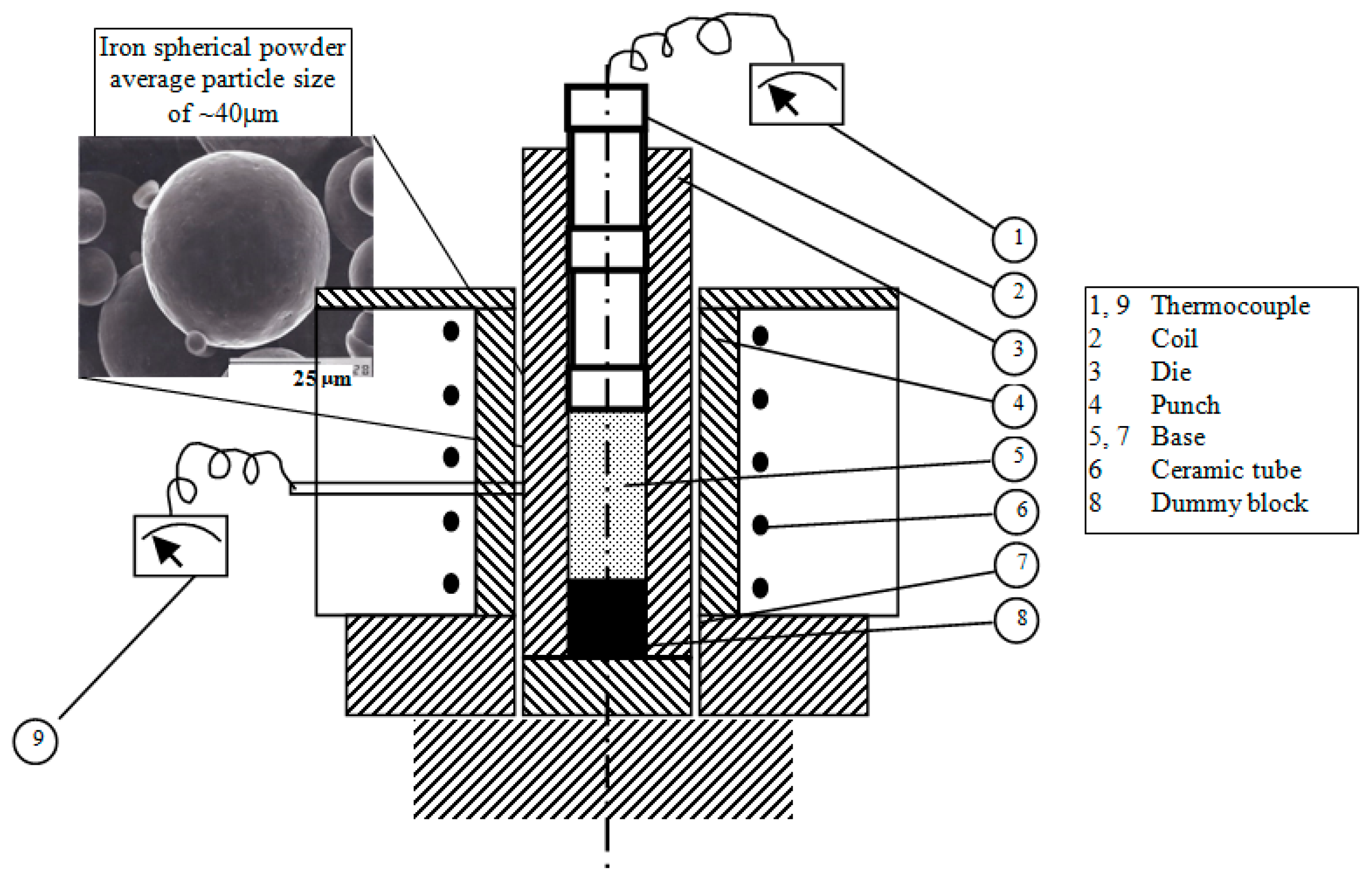
A commercial pure iron powder reduced by hydrogen, with 99.1% purity, average particle size of ~40 μm, molecular weight of 55.845 g/mol, and a density of 7.845 g/cm3, was mechanically mixed thoroughly with aluminum powders as reinforcement, with 99.9% purity, average particle size of ~10 μm, mesh No. 80, molecular weight of 26.98 g/mol, and a density of 2.9 g/cm3. The iron metallic powder was obtained from CNPC powder (Charlottetown, PE, Canada), whereas the aluminum metallic powder was obtained from ALDRICH (Darmstadt, Germany). The two metallic powders were mechanically mixed to study the effect of the aluminum addition on the mechanical and the wear properties of the iron based alloys. The weights of powders were calculated, to manufacture specimens of iron based alloys with Al additives ranging within 1, 2, 3, 5 and 10 in wt. %.
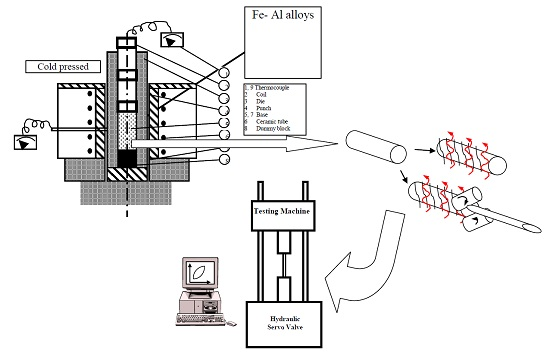
An arrangement of single acting piston cylinder, at room temperature, was adopted to perform the compaction process, as shown in Figure 1. The arrangement aimed obtaining dimensions of the green compact of 30 mm in diameter and 50 mm in height. The temperature was maintained at the desired level with a tolerance of ±5 °C. A pressing pressure of 909 MPa with cold pressing was calculated, with the assumption that the cross section area of the compact is equal to the cross section area of the die [8];
where P is the pressing pressure (MPa), F is the load (N) and D is the die diameter (mm). Various temperatures of molds were experienced with a maximum of 500 °C, while maintaining a pressure of 445.6 MPa with hot pressing and fixed cross head velocity of 2 mm/min. The setup was; consequently, heated then maintained for half an hour at the chosen temperature, for the sake of reaching temperature homogeneity all over the powder alloy. Afterwards, a reduction of the forming pressure was taken place for all tested hot components. Consequently after the compact operation, samples were enclosed using foils of aluminum surrounded with a graphite powder to shield its surface from the atmosphere during the sintering process, avoiding any potential reaction with oxygen and nitrogen. The cold and hot compacts were then sintered at 800 °C for one hour before being, finally, furnace cooled. The radial strength of the sintered pressed samples was determined using ASTM B939-15 standards [23,24], whereby annular compacts are crushed; the radial strength was calculated as:
where RS is the radial strength (MPa), Lc is the crushing load at failure (N), T is the compact wall thickness (mm), D is the outer compact diameter (mm), and h (mm)is the height of the compact mass of specimen and its cross section were constant. The final compact height hc was calculated as follow [25]:
where ho is the initial compact height after 1 ton pressing, (RD)i is the initial relative density, the (RD)c is the compact relative density after sintering. The initial relative density can be calculated as follow:
where ρc is the compact density (g/cm3). The compact relative density after sintering can be calculated from Equation (5), and the compact relative density is calculated according to Equation (6);
where ρm is the measured compact density, wi % is the weight fraction of element i, ρi is the density of element i, and n is the element’s number. The compressibility factor Cf of the metal powder was calculated using Equation (7) [26,27];
where ρo is the apparent density of the powder (g/cm3), and P is the applied pressure. The porosity was calculated after the sintering process for each specimen according to θ = 1 − (RD)c. Metallographic specimens were then prepared by polishing and etching done mechanically in a solution of 20 mL HNO3 + 10 mL H2SO4 + 20 mL H2O then cleaned by a solution of 10 mL NaOH + 100 mL H2O. Brinell hardness was measured using a 5 mm in diameter hardened ball, at 750 Kg load for 15 s.
3. Results and Discussion
3.1. Microstrautral Optical Investigations
The microstructure investigation on the Fe-based alloys was conducted using a Jeol 5400 scanning electron microscope (SEM) unit. It is connected to an EDS detector attachment used to detect various particle properties after the manufacture process. Particle size, morphology, shape, and agglomeration are obtained. The aluminum contents ranging within 1, 2, 3, 5 and 10 in wt. % were added to the iron powder and then produced using cold and hot pressing techniques. The measurements were carried out three times under the same conditions, to ensure repeatability. The achieved theoretical density after the sintering of the cold pressing samples was found to be 95% from the solid density.
3.1.1. Cold Pressed
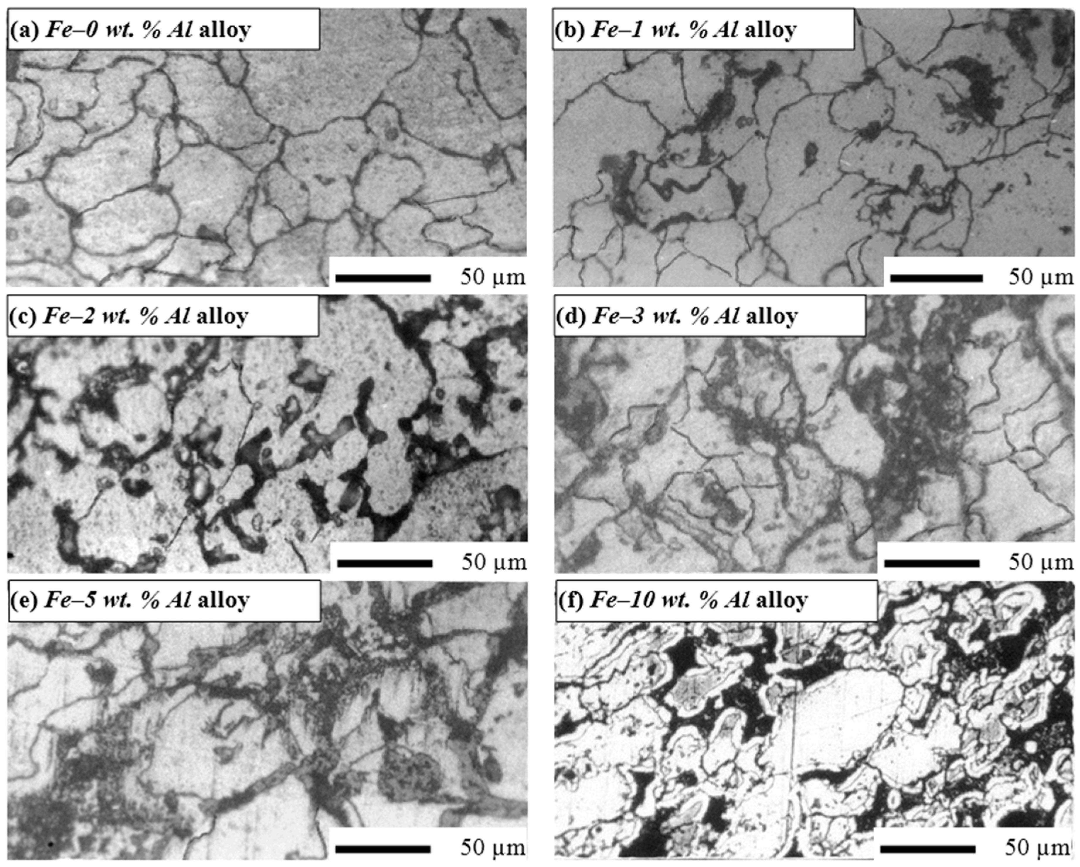
Figure 2 shows the optical micrographs of the cold pressed (CP) Fe-based alloys with aluminum contents ranging within 1, 2, 3, 5 and 10 in wt. % at a pressing pressure of P = 909 MPa followed by a sintering process at 800 °C for one hour followed by furnace cooling process. The pure iron specimens were sintered at higher temperature up to 900 °C for one hour followed by furnace cooling process. The sintering process resulted in reducing the specimen’s porosity due to coalescence processes between powders and eliminating the specimen’s pores. It creates new distinctive solid–solid interface, and reduces the free energy occurring during sintering on the 1 μm particles to a 1 cal/g decrease. On a microscopic scale, varying pressure and free energy across the curved surface affect obviously the material transfer. In other words, the increase of small particle size with high curvature results in augmenting the differences in free energy across the curved surface [28,29,30,31,32].
It is noticed in Figure 2c,d that a fine dispersion of precipitates occurs at the grain surface. The uniform distribution of the Fe and Al in the homogenous structures was noticed in alloys with Al additions of 2 or 3 wt. % compared to the rest of the Fe-based matrix alloys. Fast growth of the iron grains during sintering was observed as one of the limitations of the cold pressed PM method. In addition, it should be reported that surface cracks in the Fe–10 wt. % Al alloy were encountered.
3.1.2. Hot Pressed
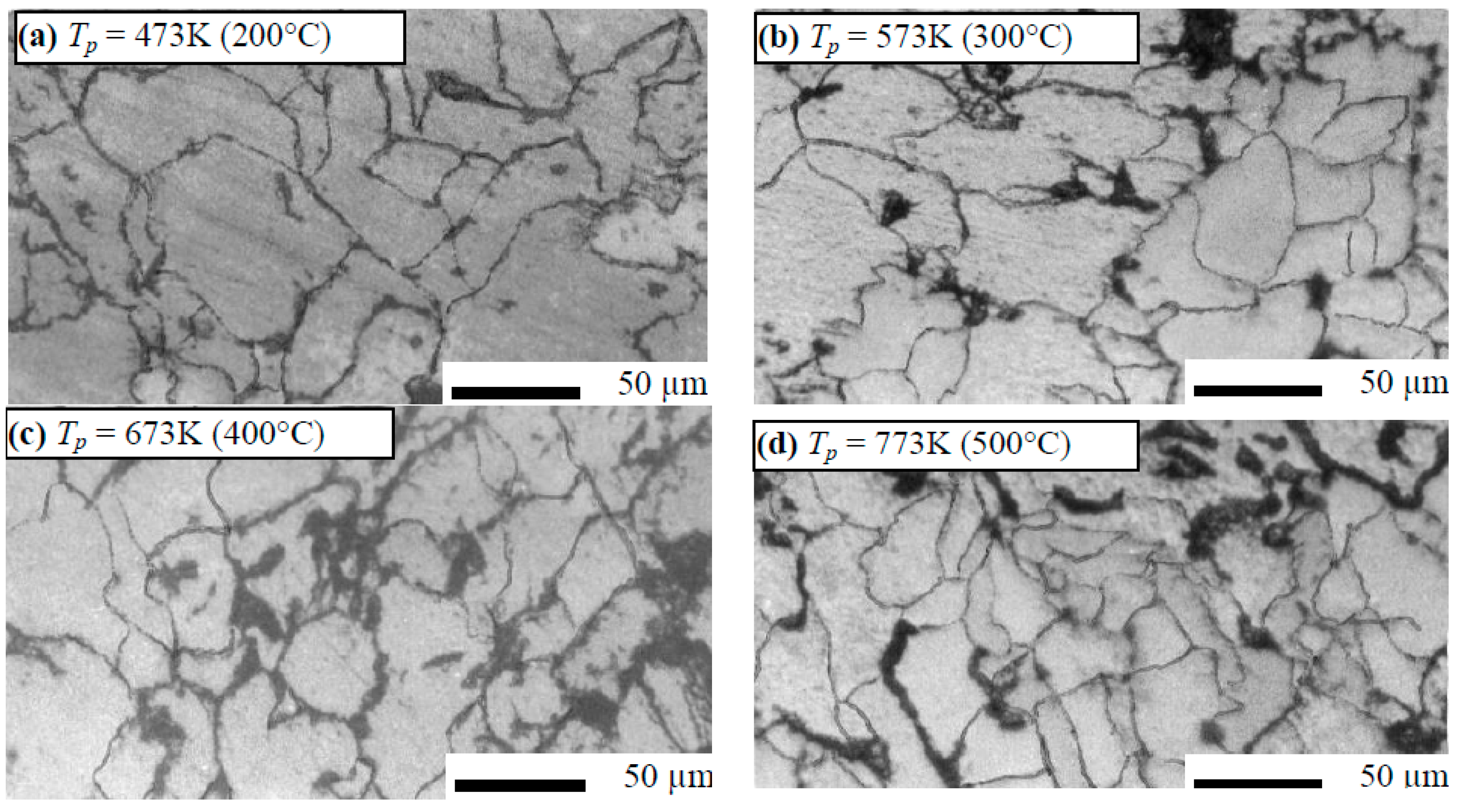
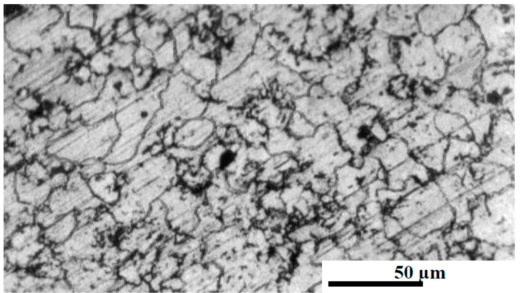
Hot pressing (HP) technique followed by heat treatment was performed to avoid the limitations observed under the cold compaction technique. The Fe–5 wt. % Al and Fe–10 wt. % Al alloys were selected to conduct the hot pressing process. The specimens were pressed at 445.6 MPa, under a pressing temperature ranging from 200 to 500 °C, followed by a heat treatment for one hour duration, at a temperature of 800 °C, going to furnace cooling conditions of 1 °C/min [6]. The temperature was then held at the same level with a tolerance range of ±5 °C. Figure 3 shows the microstructure of the hot pressed Fe–5 wt. % Al alloys samples with various pressing temperatures (TP).
The hot pressed samples followed by heat treatment showed very fine and uniformly dispersed Fe–5 wt. % Al alloys, precipitated around the grain boundaries, with an average particle size of ~5 µm in the Fe-based matrix. Figure 4 shows a homogenous structure of Fe–10 wt. % Al alloy, which was obtained with heat treatment at 800 °C for one hour and furnace cooling as the cracks after the sintering process had disappeared.
3.2. Hardness and Radial Crushing Strength
A minimum of ten readings were taken for the different cases to guarantee consistency of the Brinell hardness values crosswise the surface of material; the average of the readings is presented in Table 1. Radial strength tests were performed using an Instron 8562 universal mechanical tester under quasi static loading and a strain rate of 8 × 10⁻⁵ ± 5% s−1, at laboratory temperature. Specific dimensions of cylindrical specimens were set at a 30 mm diameter and a height of 50 mm. The samples went through deformation until crashed. Three similar samples were arranged for every test situation and subjected to the same loading conditions, to guarantee homogeneity and consistency. The average test value of all the three samples of the radial crushing strength was reported in Table 1. By increasing the Al content to 10 wt. % in the base Fe-based matrix, the Brinell hardness number was reduced from 780 to 690 and the radial strength from 380 to 228 MPa, as shown in Table 1. The hardness and radial strength of Fe–10 wt. % Al alloy was considerably lower than that of the Fe–0 wt. % Al alloy with a reduction of 11.5% and 40%, respectively. This reduction was due to a combined effect of the Fe-base matrix with the Al powder, which causes strengthening of the alloy matrix.
The Al phase was dispersed in many pools or lakes, present in the cylindrical crashed Fe-base alloy samples. The cold pressed Fe–based alloys with the addition of Al were detected to go through fine crystallization, as presented in the SEM in Figure 5a for Fe–5 wt. % Al and Figure 5b for Fe–10 wt. % Al alloys. Fine crystal precipitation in the Fe–Al alloys was detected within vein protrusions, on the surface of compression fracture, and all along the paths of the rough crack propagation; additionally, within shear bands resulting from bending [33].
The effect of the pressing temperature on the density, relative density, and compressibility factor of the Fe–5 wt. % Al alloy is shown in Figure 6a. The compact density and porosity are affected by the pressing temperature, as shown in Figure 6b; in other words, the density increases by increasing the temperature, which leads to porosity minimization. Higher relative density (RD) was reached for hot pressing Fe–5 wt. % Al alloy samples to ~95% from the solid density. Compressibility was used to indicate that the density of the powder had increased by a given pressure. By increasing the pressing temperature, the compressibility factor of the Fe–5 wt. % Al alloy was increased, as shown in Figure 6b, where augmented relative density and porosity reduction of the compact were detected. The porosity has already been presented in the green compacts. The pores formed during the sintering process were causing a different type of porosity, due to the formation of transient liquid phase during sintering, where the liquid phase penetrates into the matrix grain boundaries. Due to satisfactory wetting of the matrix by the melt, the alloying element particles replaced the pores and the homogenization leads to an overall expansion of the material during sintering.
The hot pressed compact quality was identified by the correlation with the three process parameters: time, pressure, and temperature. These variables had a major effect on the microstructure, physical properties, dimensional accuracy, and surface condition of the product. For the powders heated to low temperatures, pressure had the same effect as in cold pressing. Particles were brought closer together and were rotated and deformed, sheared, or fractured. At elevated temperatures, plastic deformation becomes the dominant mechanism. The liquid phase was formed at the hot pressing temperature and consolidation was further enhanced, by the isostatic action of the compressive stresses on the compact inside the dies [26,34,35]. Additionally, diffusion rates were increased through enhancing the liquid phase and densification, by good wetting between liquid and solid components of the alloy system.
3.3. Wear Resitance
Dry sliding wear tests were done using pin-on-disc apparatus for the Fe-based alloys with aluminum contents of 1, 2, 3, 5 and 10 in wt. % compared to stainless steel. Cylindrical specimens with 30 mm in diameter and height of 50 mm were slid against a rotating steel disc at various sliding speeds as follow: 0.33, 0.51, and 0.82 m/s. The severities of the harder material surface of the stainless steel using a pin-on-disc device was a turn over act on the surface of the Fe-based alloys. The applied wear pressure ranging from 2.2 to 3.56 MPa and duration tests from 15 to 60 min were used. The wear rate was calculated using mass losses divided by the product of the density and the sliding distance. Mass loss was measured using a precise digital balance of 170 g capacity with an accuracy of ±0.05 g. Figure 7 shows the effect of wear parameters on the wear rate (WR) for cold and hot pressing Fe-Al alloys using abrasive wear tester [21,22,36,37,38], the wear rate (WR) was calculated using the following equation:
where Wl is the weight of the different alloy, ρ is the production density of compact alloy, SS is the sliding speed, and t is the wear time.
The wear rate of Fe-base alloys with Al powder addition was much lower than the one without addition of Al element to the iron base matrix, at various wear parameters. The wear rate at higher speed was much lower than the one at lower sliding speed as shown in Figure 7b. Comparison of the wear behavior for the alloys produced, using different powder metallurgy techniques, is shown in Figure 7a,b. A significant reduction in wear rate was obtained using Fe-Al alloys in comparison with the Fe–0 wt. % Al alloy. While the addition of Al element powder to the Fe-base matrix causes a reduction in the wear rate, which increased the wear resistance up to five times compared with the alloy without Al addition, as shown in Figure 7a,b.
Figure 8 shows the wear behavior of Fe–2 wt. % Al alloy (cold pressing) under different wear pressures. It is clear that increasing the wear pressure resulted in increasing the materials loss, which is a regular known behavior for many metals and all alloys, regarding wear reactions. Hardness plays the predominant role at light wear process, while plasticity has big role at heavy operating conditions [39]. Heat generated due to the friction at high speed affects the microstructure, reduces hardness, and causes thermal stresses in the alloy matrix. As a result, a change in the wear mechanism takes place from abrasive to adhesive wear. Therefore, the worn surface layer is removed and the friction surface is protected from more wear and motion is facilitated, due to the relatively low value of shear strength [40,41].
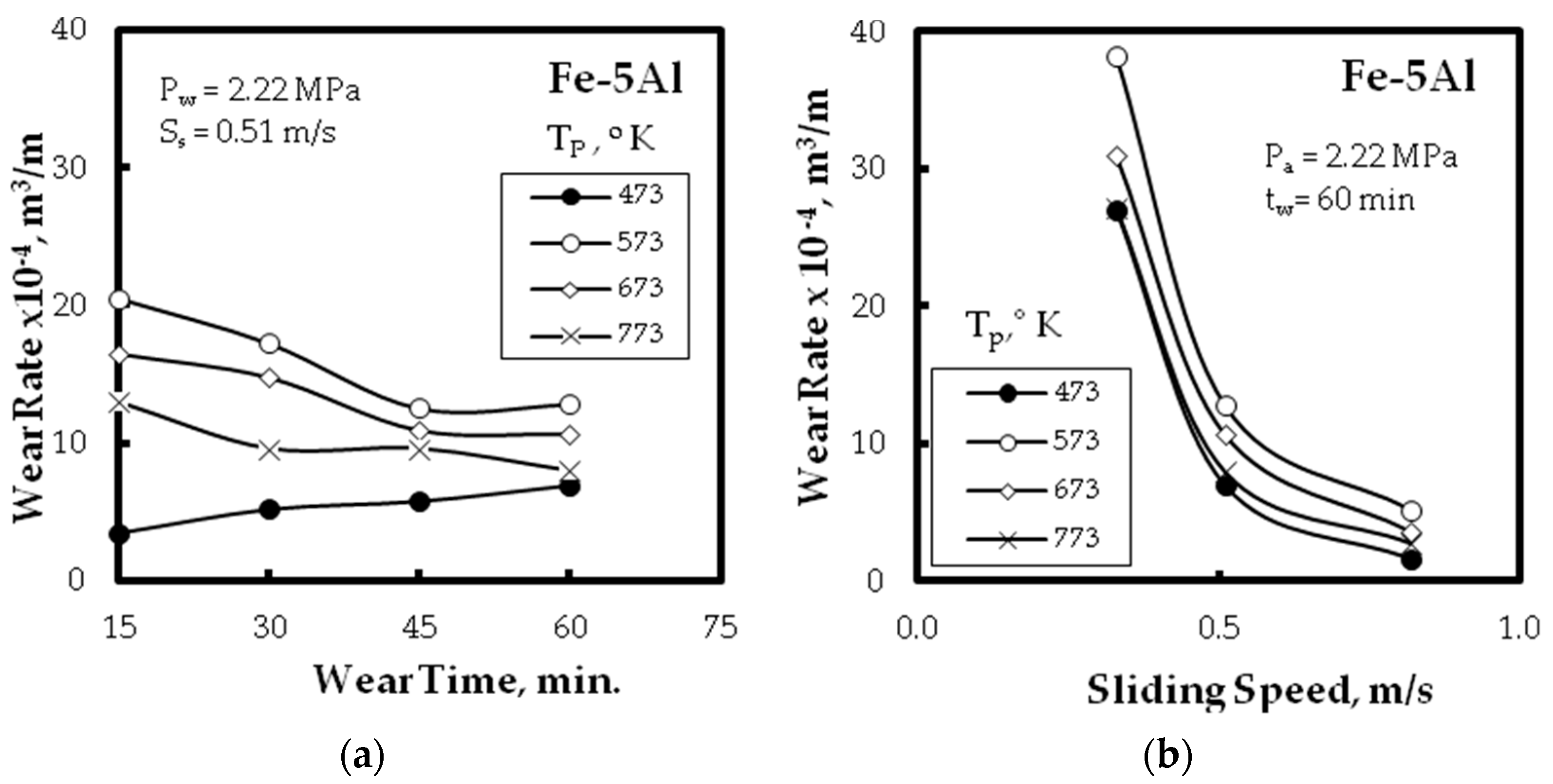
The relation between the wear rate and wear time of the Fe–5 wt. % Al alloy pressed at different pressing temperatures is shown in Figure 9a, while Figure 9b shows the relation between the wear rate and the sliding speed of the Fe–5 wt. % Al alloy pressed at the same pressing temperatures. The highest wear rate of hot pressed specimen (300 °C) was due to its coarsening structure and the pressing temperature, which was not enough to precipitate the Fe-Al alloys hard phase around the grain boundaries. The lower wear rate of hot pressed specimens at 400 or 500 °C could be attributed to its finer grain structure and spheroidization of the pores after the sintering process. In general, there was a decrease in the wear rate for the hot pressed Fe-Al alloy sampled at 200 °C and an increase in the wear rate with increasing the hot pressing temperature, under the same wear parameters, as presented in Figure 9a,b. This finding could be attributed to the decrease of the residual porosity by increasing the pressing temperature.
4. Conclusions
Based on the findings of this study, the following conclusions could be summarized:
- Under laboratory conditions and without the use of lubricant or binder, it was possible to produce Fe-Al with Al additives ranging within 1, 2, 3, 5 and 10 in wt. % alloys, using two powder metallurgy techniques, namely, cold and hot pressed, having comparable theoretical density and properties of the solid metals. Uniform distribution of dispersed phase inside the alloy structure was obtained.
- By augmenting the Al content to 10 wt. % in the base Fe-based matrix, the Brinell hardness number was reduced from 780 to 690 MPa and the radial strength from 380 to 228 MPa, with a reduction of 11.5%, and 40%, respectively. The reduction of the compressibility factor of hot pressed powder alloys was detected with increasing the hot pressing temperature up to 500 °C.
- Improvement of the wear resistance was observed, with augmenting the Al powder to the Fe matrix up to five times compared with the alloy without Al additions for different wear parameters: wear time, and sliding speed. This was also detected for the different PM technique.
- The hot compact of Fe-Al alloys of about 95% theoretical density can be obtained from the metal powders, by employing a pressure of about 445.6 MPa and temperature of 500 °C. These alloys had higher density, better wear resistance, and homogenous structure than the parts produced by separate compaction and sintering obtained after elemental powders were added.
Author Contributions
All authors contributed equally in designing and manufacturing of the studied alloys, conceiving, designing and performing the experiments, collecting and analyzing the data, and finally discussion association of the results. I would like to also indicate that the corresponding author was responsible for addressing all reviewers’ remarks and journal correspondence.
Conflicts of Interest
The authors also declare no conflict of interest.
References
- Caballero, E.S.; Cintas, J.; Cuevas, F.G.; Montes, J.M.; Ternero, F. Influence of Milling Atmosphere on the Controlled Formation of Ultrafine Dispersoids in Al-Based MMCs. Metals 2016, 6, 224. [Google Scholar] [CrossRef]
- Luka, F.; Vilemova, M.; Nevrla, B.; Klecka, J.; Chraska, T. Properties of Mechanically Alloyed W-Ti Materials with Dual Phase Particle Dispersion. Metals 2017, 7, 3. [Google Scholar] [CrossRef]
- Chen, C.L.; Lin, C.H. A Study on the Aging Behavior of Al6061 Composites Reinforced with Y2O3 and TiC. Metals 2017, 7, 11. [Google Scholar] [CrossRef]
- El-Hadek, M.A. Numerical simulation of the inertia friction welding process of dissimilar materials. Metall. Trans. B 2014, 45, 2346–2356. [Google Scholar] [CrossRef]
- Nassef, A.; El-Hadek, M. Mechanics of hot pressed aluminum composites. Int. J. Adv. Manuf. Technol. 2015, 76, 1905–1912. [Google Scholar] [CrossRef]
- Nassef, A.; El-Hadek, M. Microstructure and Mechanical Behavior of Hot Pressed Cu-Sn Powder Alloys. Adv. Mater. Sci. Eng. 2016, 2016, 9796169. [Google Scholar] [CrossRef]
- Kim, S.H.; Kim, H.; Kim, N.J. Brittle intermetallic compound makes ultrastrong low-density steel with large ductility. Nature 2015, 518, 77–79. [Google Scholar] [CrossRef] [PubMed]
- Köster, W.; Tonn, W. The Iron Corner of the Iron-Manganese-Aluminium System. Arch. Eisenhuettenwes 1933, 7, 365–366. [Google Scholar]
- James, P.J. Precipitation of the Carbide-FEMN-3 ALC IN AN Iron-Aluminium Alloy. J. Iron Steel Inst. 1969, 207, 54–57. [Google Scholar]
- Furushima, R.; Katou, K.; Shimojima, K.; Hosokawa, H.; Mikami, M.; Matsumoto, A. Effect of η-phase and FeAl composition on the mechanical properties of WC–FeAl composites. Intermetallics 2015, 66, 120–126. [Google Scholar] [CrossRef]
- Amaya, M.; Romero, J.M.; Martinez, L.; Pérez, R. Mechanical Properties of Spray-Atomized FeAl40 at. % Al Alloys. In Materials Characterization; Springer International Publishing: Cham, Switzerland, 2015; Volume 5, pp. 199–207. [Google Scholar]
- Trotter, G.; Baker, I. The effect of aging on the microstructure and mechanical behavior of the alumina-forming austenitic stainless steel Fe–20Cr–30Ni–2Nb–5Al. Mater. Sci. Eng. A 2015, 627, 270–276. [Google Scholar] [CrossRef]
- Zamanzade, M.; Barnoush, A.; Motz, C. A Review on the Properties of Iron Aluminide Intermetallics. Crystals 2016, 6, 10. [Google Scholar] [CrossRef]
- Tanaka, Y.; Kainuma, R.; Omori, T.; Ishida, K. Alloy Design for Fe-Ni-Co-Al-based Superelastic Alloys. Mater. Today Proc. 2015, 2, S485–S492. [Google Scholar] [CrossRef]
- Ikeda, O.; Ohnuma, I.; Kainuma, R.; Ishida, K. Phase equilibria and stability of ordered BCC phases in the Fe-rich portion of the Fe–Al system. Intermetallics 2001, 9, 755–761. [Google Scholar] [CrossRef]
- Kim, H.; Suh, D.W.; Kim, N.J. Fe–Al–Mn–C lightweight structural alloys: A review on the microstructures and mechanical properties. Sci. Technol. Adv. Mater. 2013, 14, 014205. [Google Scholar] [CrossRef] [PubMed]
- Frommeyer, G.; Bruex, U. Microstructures and mechanical properties of high-strength Fe-Mn-Al-C light-weight TRIPLEX steels. Steel Res. Int. 2006, 77, 627–633. [Google Scholar] [CrossRef]
- Sutou, Y.; Kamiya, N.; Umino, R.; Ohnuma, I.; Ishida, K. High-strength Fe-20Mn-Al-C-based alloys with low density. ISIJ Int. 2010, 50, 893–899. [Google Scholar] [CrossRef]
- Greer, A.L.; Rutherford, K.L.; Hutchings, I.M. Wear resistance of amorphous alloys and related materials. Int. Mater. Rev. 2002, 47, 87–112. [Google Scholar] [CrossRef]
- Maupin, H.E.; Wilson, R.D.; Hawk, J.A. Wear deformation of ordered Fe-Al intermetallic alloys. Wear 1993, 162, 432–440. [Google Scholar] [CrossRef]
- Xu, B.; Zhu, Z.; Ma, S.; Zhang, W.; Liu, W. Sliding wear behavior of Fe–Al and Fe–Al/WC coatings prepared by high velocity arc spraying. Wear 2004, 257, 1089–1095. [Google Scholar] [CrossRef]
- Kim, Y.S.; Kim, Y.H. Sliding wear behavior of Fe 3 Al-based alloys. Mater. Sci. Eng. A 1998, 258, 319–324. [Google Scholar] [CrossRef]
- Chonglin, W. Discussion on radial crushing strength testing. Powder Metall. Technol. 1996, 8, 206–211. [Google Scholar]
- Candela, N.; Plaza, R.; Rosso, M.; Velasco, F.; Torralba, J.M. Radial crushing strength and microstructure of molybdenum alloyed sintered steels. J. Mater. Process. Technol. 2001, 119, 7–13. [Google Scholar] [CrossRef]
- Larker, H.T.; Larker, R. Hot isostatic pressing. Mater. Sci. Technol. 1991. [Google Scholar] [CrossRef]
- Leuenberger, H.; Rohera, B.D. Fundamentals of powder compression. I. The compactibility and compressibility of pharmaceutical powders. Pharm. Res. 1986, 3, 12–22. [Google Scholar] [CrossRef] [PubMed]
- Hryha, E.; Dudrova, E.; Bengtsson, S. Influence of powder properties on compressibility of prealloyed atomised powders. Powder Metall. 2008, 51, 340–342. [Google Scholar] [CrossRef]
- El-Hadek, M.A.; Kaytbay, S.H. Fracture properties of SPS tungsten copper powder composites. Metall. Trans. A 2013, 44, 544–551. [Google Scholar] [CrossRef]
- Kaytbay, S.; El-Hadek, M. Wear resistance and fracture mechanics of WC–Co composites. Int. J. Mater. Res. 2014, 105, 557–565. [Google Scholar] [CrossRef]
- El-Hadek, M.A.; Kassem, M. Failure behavior of Cu–Ti–Zr-based bulk metallic glass alloys. J. Mater. Sci. 2009, 44, 1127–1136. [Google Scholar] [CrossRef]
- El-Hadek, M.; Kaytbay, S. Characterization of copper carbon composites manufactured using the electroless precipitation process. Mater. Manuf. Process. 2013, 28, 1003–1008. [Google Scholar]
- El-Katatny, S.M.; Nassef, A.E.; El-Domiaty, A.; El-Garaihy, W.H. Fundamental Analysis of Cold Die Compaction of Reinforced Aluminum Powder. Int. J. Eng. Tech. Res. 2015, 3, 180–184. [Google Scholar]
- Ahari, F. Flexible High Radial Strength Stent. U.S. Patent 6,264,685, 24 July 2001. [Google Scholar]
- Chtourou, H.; Guillot, M.; Gakwaya, A. Modeling of the metal powder compaction process using the cap model. Part I. Experimental material characterization and validation. Int. J. Solids Struct. 2002, 39, 1059–1075. [Google Scholar] [CrossRef]
- Bocchini, G.F. Warm compaction of metal powders: Why it works, why it requires a sophisticated engineering approach. Powder Metall. 2013, 42, 171–180. [Google Scholar] [CrossRef]
- Wang, J.; Xing, J.; Cao, L.; Su, W.; Gao, Y. Dry sliding wear behavior of Fe3Al alloys prepared by mechanical alloying and plasma activated sintering. Wear 2010, 268, 473–480. [Google Scholar] [CrossRef]
- Sharma, G.; Limaye, P.K.; Ramanujan, R.V.; Sundararaman, M.; Prabhu, N. Dry-sliding wear studies of Fe3Al-ordered intermetallic alloy. Mater. Sci. Eng. A 2004, 386, 408–414. [Google Scholar] [CrossRef]
- Dhokey, N.B.; Rane, K.K. Wear behavior and its correlation with mechanical properties of TiB2 reinforced aluminium-based composites. Adv. Tribol. 2011, 2011, 837469. [Google Scholar] [CrossRef]
- Tong, C.J.; Chen, M.R.; Yeh, J.W.; Lin, S.J.; Chen, S.K.; Shun, T.T.; Chang, S.Y. Mechanical performance of the Al x CoCrCuFeNi high-entropy alloy system with multiprincipal elements. Metall. Trans. A 2005, 36, 1263–1271. [Google Scholar] [CrossRef]
- Hsu, C.Y.; Yeh, J.W.; Chen, S.K.; Shun, T.T. Wear resistance and high-temperature compression strength of Fcc CuCoNiCrAl0. 5Fe alloy with boron addition. Metall. Trans. A 2004, 35, 1465–1469. [Google Scholar] [CrossRef]
- Chen, M.R.; Lin, S.J.; Yeh, J.W.; Chuang, M.H.; Chen, S.K.; Huang, Y.S. Effect of vanadium addition on the microstructure, hardness, and wear resistance of Al0.5CoCrCuFeNi high-entropy alloy. Metall. Trans. A 2006, 37, 1363–1369. [Google Scholar] [CrossRef]
Figure 1.
The setup of die of PM pressing technique.

Figure 2.
Optical micrographs of (a) Fe-0 wt. % Al, (b) Fe-1 wt. % Al, (c) Fe-2 wt. % Al, (d) Fe-3 wt. % Al, (e) Fe-5 wt. % Al, (f) Fe-10 wt. % Al alloys cold pressed at pressure of 909 MPa followed by sintering process of at 800 °C per one hour at constant furnace cooling conditions.
Figure 2.
Optical micrographs of (a) Fe-0 wt. % Al, (b) Fe-1 wt. % Al, (c) Fe-2 wt. % Al, (d) Fe-3 wt. % Al, (e) Fe-5 wt. % Al, (f) Fe-10 wt. % Al alloys cold pressed at pressure of 909 MPa followed by sintering process of at 800 °C per one hour at constant furnace cooling conditions.

Figure 3.
Microstructure of Fe–5 wt. % Al alloys hot pressed at (a) 200 °C, (b) 300 °C, (c) 400 °C, (d) 500 °C.
Figure 3.
Microstructure of Fe–5 wt. % Al alloys hot pressed at (a) 200 °C, (b) 300 °C, (c) 400 °C, (d) 500 °C.

Figure 4.
Microstructure of hot pressed Fe–10 wt. % Al alloy with heat treatment at 800 °C for one hour and furnace cooling conditions.
Figure 4.
Microstructure of hot pressed Fe–10 wt. % Al alloy with heat treatment at 800 °C for one hour and furnace cooling conditions.

Figure 5.
SEM micrographs of the rough fracture surface morphology of the CP Fe-based alloys: (a) Fe–5wt. % Al; and (b) Fe–10 wt. % Al.
Figure 5.
SEM micrographs of the rough fracture surface morphology of the CP Fe-based alloys: (a) Fe–5wt. % Al; and (b) Fe–10 wt. % Al.
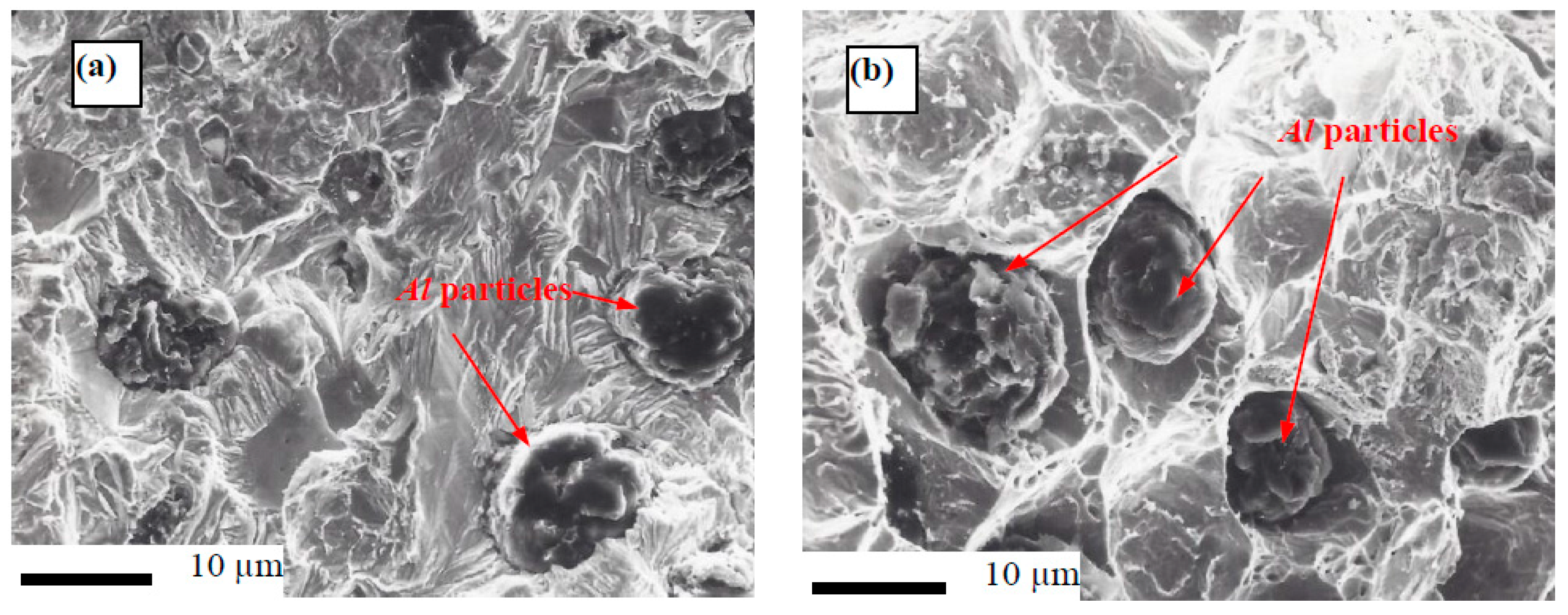
Figure 6.
(a) The effect of pressing temperature on the compact relative density (RD) and compressibility factor (Cf); and, (b) the effect of the pressing temperature on the compact density and porosity, for Fe–5 wt. % Al alloys.
Figure 6.
(a) The effect of pressing temperature on the compact relative density (RD) and compressibility factor (Cf); and, (b) the effect of the pressing temperature on the compact density and porosity, for Fe–5 wt. % Al alloys.
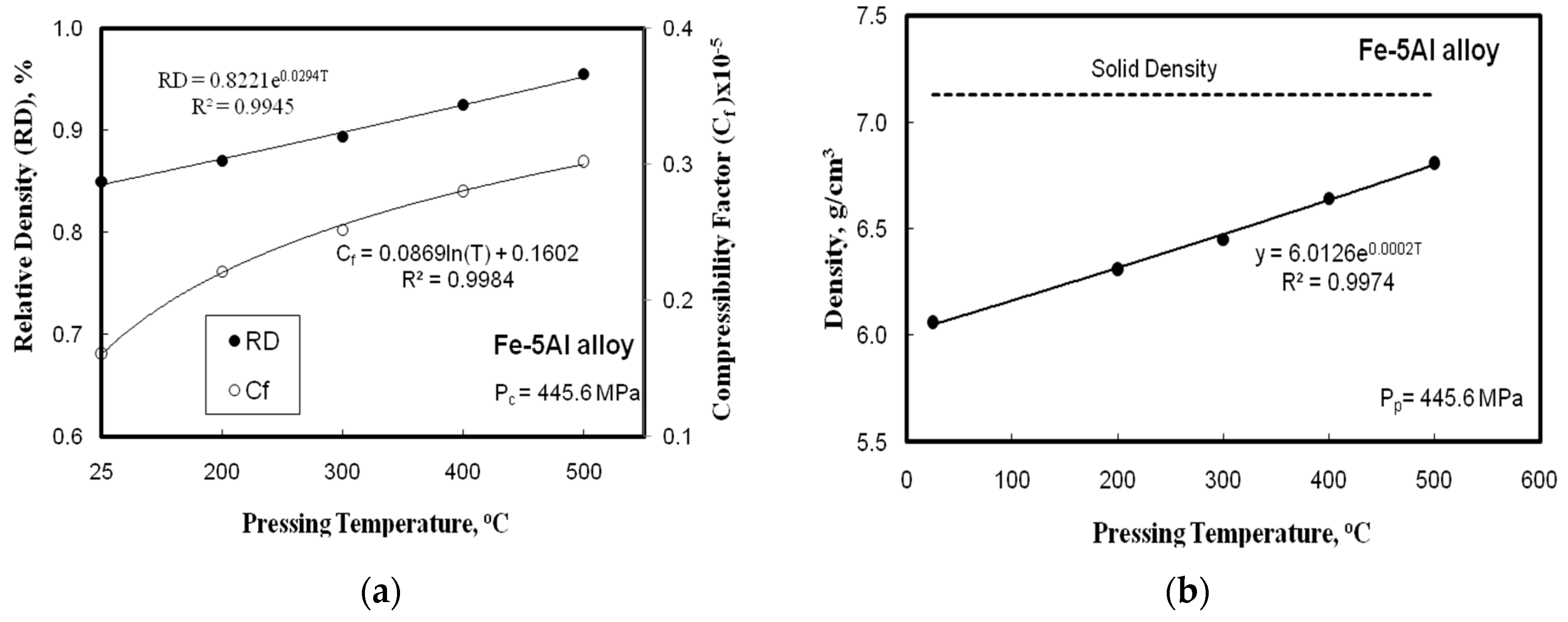
Figure 7.
The effect of wear parameter for Fe-base alloys different PM technique on: (a) wear time; and (b) sliding speed for Fe–0 wt. % Al (CP), Fe–2 wt. % Al (CP), and Fe–5 wt. % Al (HP at 200 °C) alloys, respectively.
Figure 7.
The effect of wear parameter for Fe-base alloys different PM technique on: (a) wear time; and (b) sliding speed for Fe–0 wt. % Al (CP), Fe–2 wt. % Al (CP), and Fe–5 wt. % Al (HP at 200 °C) alloys, respectively.
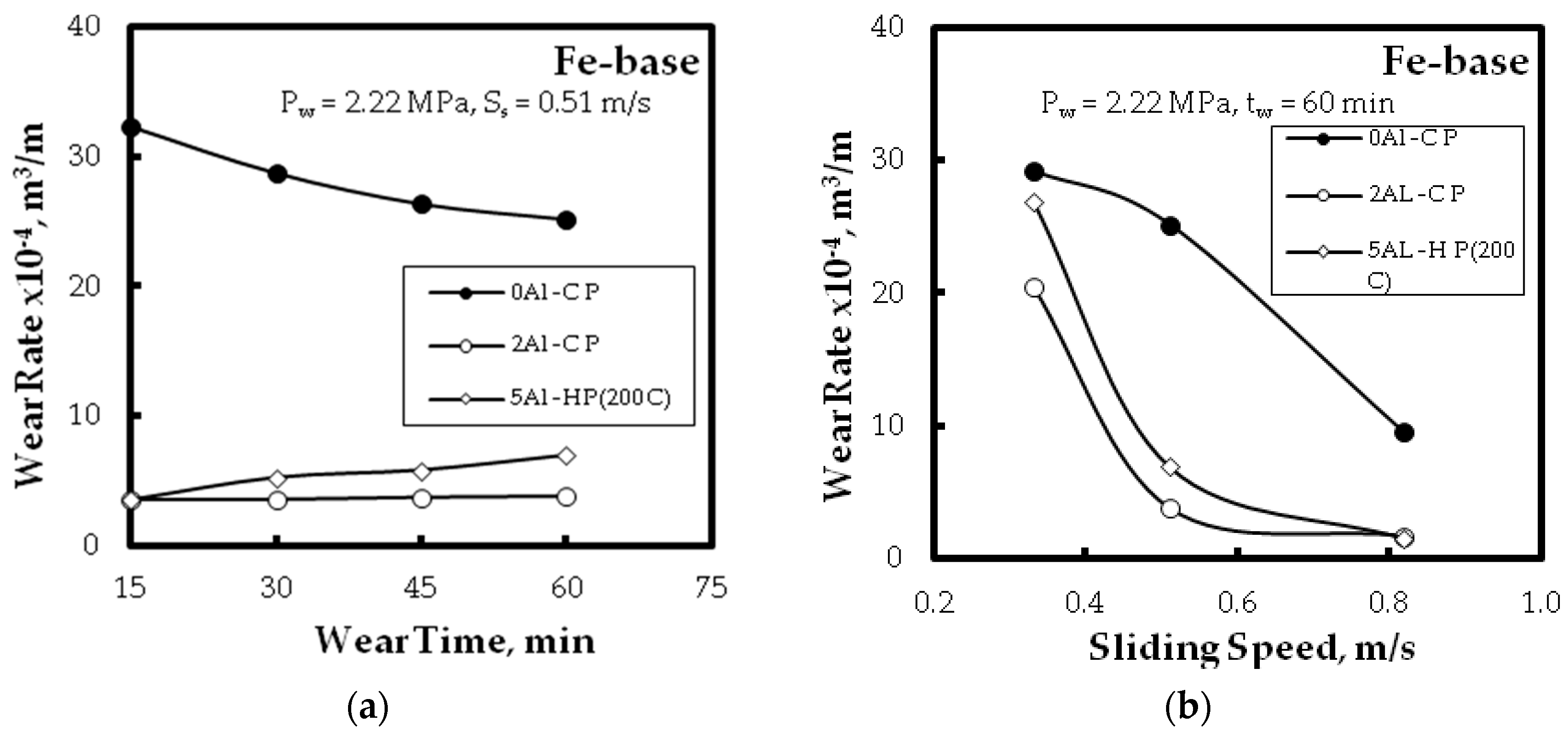
Figure 8.
The effect of wear pressure for Fe–2 wt. % Al alloy (CP) on the wear rate.
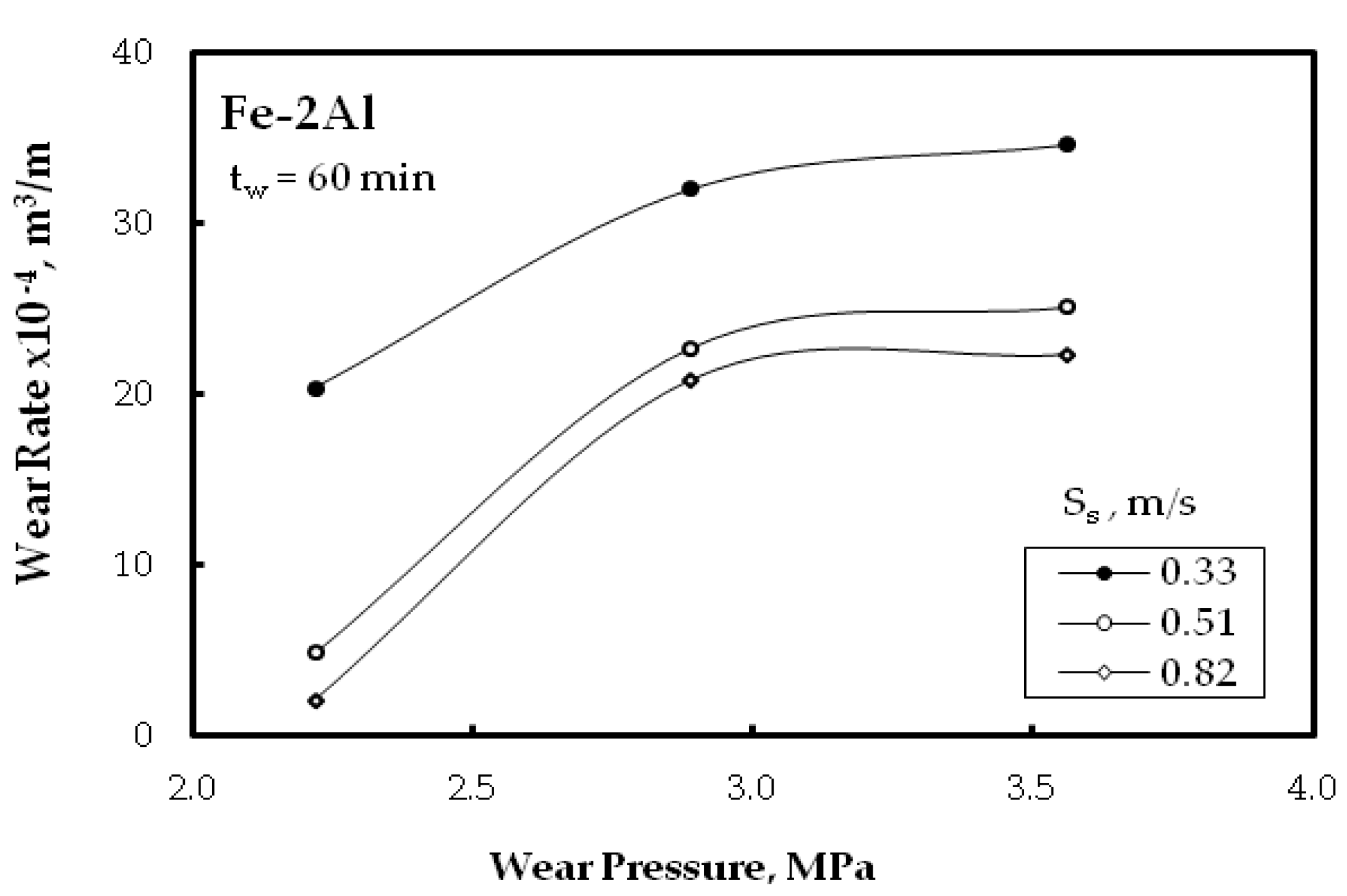
Figure 9.
The effect of wear parameters for Fe–5 wt. % Al alloy at different pressing temperature on: (a) wear time; and (b) sliding speed.
Figure 9.
The effect of wear parameters for Fe–5 wt. % Al alloy at different pressing temperature on: (a) wear time; and (b) sliding speed.


Table 1.
Brinell hardness number and the radial strength for Fe-based alloys with various Al additions.
Table 1.
Brinell hardness number and the radial strength for Fe-based alloys with various Al additions.
| Radial Strength MPa | Brinell Hardness Number | Al Content in Fe-Based Alloys wt. % |
|---|---|---|
| 380.44 | 780 | 0 |
| 369.78 | 751 | 1 |
| 344.67 | 735 | 1.5 |
| 310.11 | 722 | 2 |
| 270.23 | 714 | 2.5 |
| 245.11 | 705 | 3 |
| 235.14 | 698 | 5 |
| 230.21 | 691 | 7.5 |
| 228.43 | 690 | 10 |
© 2017 by the authors. Licensee MDPI, Basel, Switzerland. This article is an open access article distributed under the terms and conditions of the Creative Commons Attribution (CC BY) license (http://creativecommons.org/licenses/by/4.0/).
Share and Cite
MDPI and ACS Style
Nassef, A.; El-Garaihy, W.H.; El-Hadek, M. Characteristics of Cold and Hot Pressed Iron Aluminum Powder Metallurgical Alloys. Metals 2017, 7, 170. https://doi.org/10.3390/met7050170
AMA Style
Nassef A, El-Garaihy WH, El-Hadek M. Characteristics of Cold and Hot Pressed Iron Aluminum Powder Metallurgical Alloys. Metals. 2017; 7(5):170. https://doi.org/10.3390/met7050170
Chicago/Turabian StyleNassef, Ahmed, Waleed H. El-Garaihy, and Medhat El-Hadek. 2017. "Characteristics of Cold and Hot Pressed Iron Aluminum Powder Metallurgical Alloys" Metals 7, no. 5: 170. https://doi.org/10.3390/met7050170
Note that from the first issue of 2016, this journal uses article numbers instead of page numbers. See further details here.