
Mechanical Behavior and Sliding Wear Studies on Iron Aluminide Coatings Reinforced with Titanium Carbide
by
Mahdi Amiriyan
1,2, 
Carl Blais
1,2,
Sylvio Savoie
3,
Robert Schulz
3,
Mario Gariépy
4 and
Houshang D. Alamdari
1,2,* 1
Département de génie des mines, de la métallurgie et des matériaux, Université Laval, Québec, QC G1V 0A6, Canada
2
Aluminium Research Centre-REGAL, Québec, QC G1V 0A6, Canada
3
Hydro-Quebec Research Institute, Varennes, QC J3X 1S1, Canada
4
Wärtsilä Canada Incorporated, LaSalle, QC H8N 1V1, Canada
*
Author to whom correspondence should be addressed.
Metals 2017, 7(5), 177; https://doi.org/10.3390/met7050177
Submission received: 11 April 2017
/
Revised: 5 May 2017
/
Accepted: 8 May 2017
/
Published: 16 May 2017
Abstract
:Wear-resistant iron aluminide-based composites were coated on steel substrates with the High-Velocity Oxy-Fuel (HVOF) technique using ball milled Fe3Al and TiC powders as feedstock. The phase composition, microstructure, microhardness, elastic modulus and dry sliding wear performance of unreinforced Fe3Al and Fe3Al–TiC composite coatings (reinforced with 30 and 50 vol. % TiC particles) were evaluated in order to reveal the relationship between the mechanical and tribological behaviors. Compared to the unreinforced coatings, the composite coating with 30 vol. % TiC particles exhibited much greater hardness and higher elastic modulus. The increase of the elastic modulus of the composite coatings did not result in deterioration of sliding wear behavior. The addition of 50 vol. % TiC resulted in a further increase in hardness, however, both composite coatings showed the same elastic modulus. The fractured cross sectional surface of the unreinforced coating showed a weakly bonded microstructure promoting delamination in wear tests, whereas the composite fractured surface showed strong mechanical bonding between the matrix and carbide particles, leading to better cohesion. The Fe3Al–TiC coatings showed almost three orders of magnitude higher wear resistance under the dry sliding wear test compared to the unreinforced coatings.
Keywords:
thermal spray; iron aluminide coating; titanium carbide; hardness; elastic modulus; fracture; wear1. Introduction
Since the introduction of the Fe–Al intermetallics as corrosion, oxidation and sulfidation resistant candidates for many applications, FeAl and Fe3Al intermetallics have become a subject of great interest [1,2]. Fe3Al has also been suggested to be a promising binder phase for ceramic particles, such as hard carbides, for achieving higher wear resistance and better oxidation resistance [3]. Despite having competitive properties over many intermetallics and metals, iron aluminides suffer from limited ductility at room temperature (less than 5%) and poor wear resistance [4]. Basically the mediocre room temperature ductility and consequently, poor formability, has limited their utilization as bulk components. On the other hand, studies have shown that coating could be a suitable approach to overcome this drawback, taking advantage of the substrate formability and the properties of iron aluminide on the surface.
Incorporation of hard ceramic particles in iron aluminide matrix has been reported to improve the mechanical properties [5] and consequently to improve the wear resistance of Fe–Al intermetallic coatings [6]. The ceramic particles form a sub-structure throughout the coating, and are effective in supporting the external applied load during tribological actions, such as sliding wear [7,8]. Zhang et al. [9] reported that dry sliding wear resistance of hot-pressed Fe3Al/TiC bulk composites is increased by increasing the amount of TiC. The authors attributed the wear improvement to the higher hardness of the TiC-containing composites. More recently, Amiriyan et al. [7] confirmed the supporting role of in-situ TiC nanoparticles in sliding wear resistance of Fe3Al coatings. They reported that while the unreinforced Fe3Al coatings exhibited a relatively high wear rate, the Fe3Al–TiC composite coatings showed higher hardness and wear resistance as the TiC content increased. In a very recent study, Pougoum et al. [10] confirmed the beneficial effects of titanium nitride (TiN) and titanium diboride (TiB2) ceramics on the tribomechanical behavior of High-Velocity Oxy-Fuel (HVOF) deposited Fe3Al coatings.
Although hardness is an important factor determining the wear resistance of coatings, it is not the only mechanical property that governs the tribological behavior. For instance, elastic modulus is an important mechanical property among those affecting the wear resistance [8,11]. The main objective of this paper is therefore to reveal the effect of TiC reinforcement on the hardness and elastic modulus of iron aluminide coatings, aiming at correlating mechanical properties and matrix-reinforcing particle adhesion with the sliding wear behavior of the coatings. The coatings were made by the HVOF technique, using ball milled Fe3Al and pre-formed TiC particles as feedstock.
2. Materials and Methods
Starting materials in powder form (Fe3Al (<100 µm); Ametek Ltd., Eighty Four, PA, USA and TiC (<5 µm); Alfa Aesar, Ward Hill, MA, USA) were milled together for 3 h, using a high-energy ball mill (Zoz GmbH, Wenden, Germany). Two of the contents of retained TiC were chosen: 30 and 50 vol. %. The weight ratio of ball-to-powder was chosen to be 10:1 and the milling process was carried out in an argon atmosphere in order to prevent oxidation.
Mild steel plates were chosen as the substrate. Prior to deposition, the substrate plates were sand-blasted to roughen the surface and then washed with acetone. The feedstock powder was sprayed on the substrate using a Praxair JP-8000 HVOF (Concord, NH, USA) spray system. Table 1 indicates the basic projection parameters.
An X-ray diffractometer (XRD, SIEMENS, D5000, Karlsruhe, Germany) was used to identify phase composition of the starting powders and the sprayed coatings. The analysis was done with CuKα (λ = 1.54056 Å) using a scan speed and steps of 1°/min. and 0.02°, respectively. A 2θ range of 20–90 was chosen in which all major reflections of Fe3Al and TiC are covered. Microstructural studies and chemical analysis were carried out using a scanning electron microscope equipped with energy dispersive X-ray spectroscopy (EDX, PGT Avalon, Princeton Gamma Tech Instruments, Princeton, NJ, USA). Electron probe microanalysis (EPMA) was performed for elemental mapping. A high resolution SEM (Hitachi High-Technologies, SU–8230, Rexdale, ON, Canada) was utilized for microscopic analyses of the fracture surface.
In order to evaluate the mechanical properties of the coatings, microindentation was carried out on a polished cross-section of the coatings, using a CSM instrument (CSM, Peseux, Switzerland) equipped with a Vickers tip. Maximum load of indentation was 500 mN with a loading time of 30 s. The load-displacement curves, according to the most widely used standard Oliver-Pharr [12] procedure, were recorded and the mechanical properties of the coatings (hardness, elastic modulus) were evaluated. An average value of 50 indentations is reported for each specimen. The average mechanical properties reported for each specimen should not depend on local imperfections of the microstructure (such as indentation on pores or undesired phases), an example of which is shown in Figure 1 (indentation on a pore). Such uncertain hardness and elastic modulus values have been deleted before reporting the average value. A three-point bending test at room temperature was used to break the coating and study the fracture surface. Using Instron-Satec press (T20000, Grove City, PA, USA), the force was applied with a 2 mm/min speed on the opposite side of the coated surface of the sample. The sample was thus bent until large cracks appeared on the surface. The fractured surfaces of the cracks were then examined using the high-resolution scanning electron microscope.
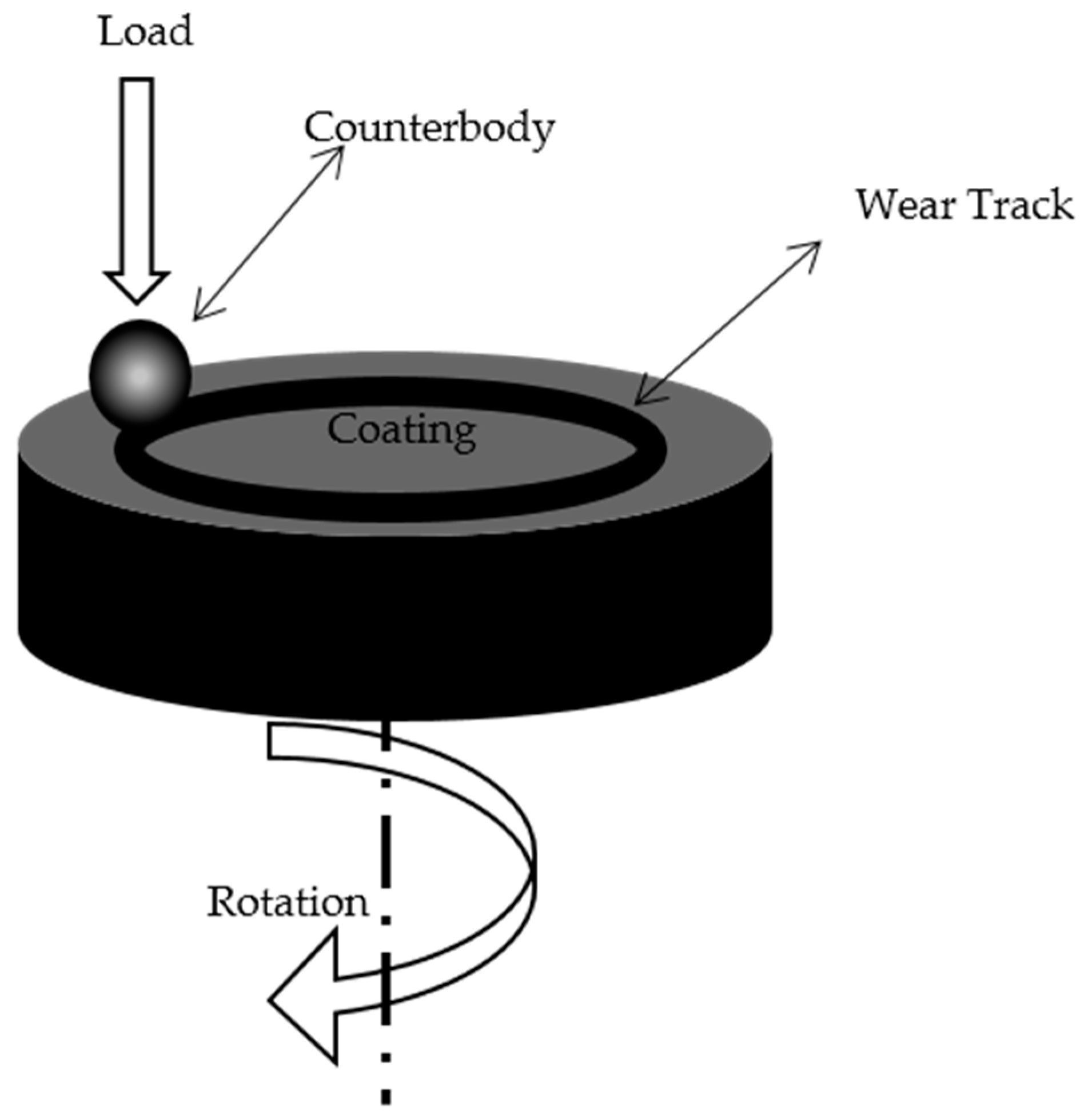
Prior to the sliding tests, the specimens were mounted in an epoxy resin and then polished to obtain a surface roughness (Ra) of about 0.8. Dry sliding wear tests (ball-on-disc) were carried in air at room temperature according to ASTM G99–05. The ball-on-disk tribometer is schematically shown in Figure 2. A 6.33 mm diameter alumina ball was used as the counterpart sliding against the coating surface. In ball-on-disk tests, it is preferable to use a harder ball than the coating in order to induce more wear on the coating rather than on the ball. Al2O3 balls with a Vickers hardness of 1700 were used in this study. Each test was conducted with a new ball in order to retain uniform test conditions. A constant load of 5 N, a sliding speed of 0.1 m·s−1 and a sliding distance of 1000 m were used during the tests. The cross-sectional worn area of the wear tracks was measured with a Dektak–150 surface profilometer (Bruker Corporation, San Jose, CA, USA) in order to calculate the worn volume. Finally, the wear rate was calculated as:
where V is the worn volume, W (N) is the applied load, and s (m) is the total sliding distance.
K = V/(W × s),
3. Results and Discussion
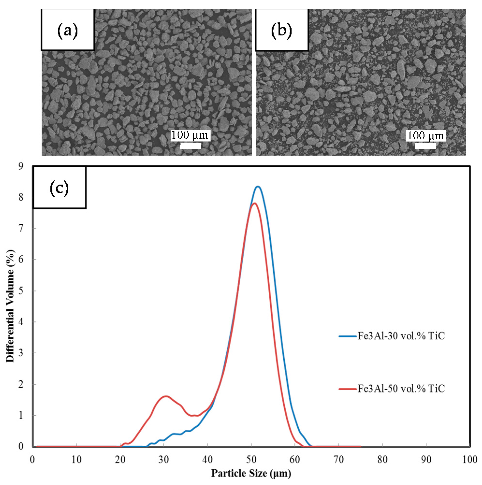
Figure 3 shows the SEM images of the Fe3Al–TiC milled composite powders. The particles have irregular shape, which is common for powders processed with high-energy ball milling. The particle size distribution profile of the milled powders (Figure 3c) shows a bimodal particle size distribution with two peaks at around 30 and 55 μm. The sample with 50 vol. % TiC shows a more pronounced peak at small sizes, which is due to the higher ceramic volume fraction, making the composite more fragile. Despite having a bimodal size distribution and irregular shape feedstock powder, this morphology and size enabled easy supply and good flow of the feedstock powder to the HVOF gun during the spraying process.
XRD patterns of the Fe3Al and TiC starting powders as well as those for the HVOF deposited composite coatings are presented in Figure 4. It is clear that the phases of the as-sprayed coatings did not significantly differ from that of the starting powders. The slight peak broadening observed in the coatings could be associated with the residual stress due to the high level of plastic deformation and the subsequent elevated cooling rate. It is shown that the samples mostly consist of two major phases, namely iron aluminide and titanium carbide, with no other detectable phases, e.g., oxide or complex decomposed carbides. In fact, the HVOF flame temperature and the particle residential time in the flame are not high enough to trigger a reaction. Similar results were reported by Isalgue et al. [13], who compared the phase composition of TiC-reinforced cermets deposited by HVOF and Plasma Spray techniques. These authors observed less decomposition of TiC during HVOF deposition.
Figure 5a shows the typical microstructure from the polished surface of a coating obtained by Fe3Al–50 vol. % TiC feedstock. The coating consists of relatively dense (porosity <5%, measured by image analyzing method) and homogenous lamellar microstructure which seems to be well-bonded to the steel substrate. The thickness is around 80 µm. Figure 5b,c show the elemental distribution of titanium and carbon, respectively, in the coating. The images reveal that the reinforcing TiC particles are fairly well distributed throughout the microstructure of the coatings. The size of the TiC particles are less than 5 µm, as expected from the initial size of the TiC particles in the milled powder.
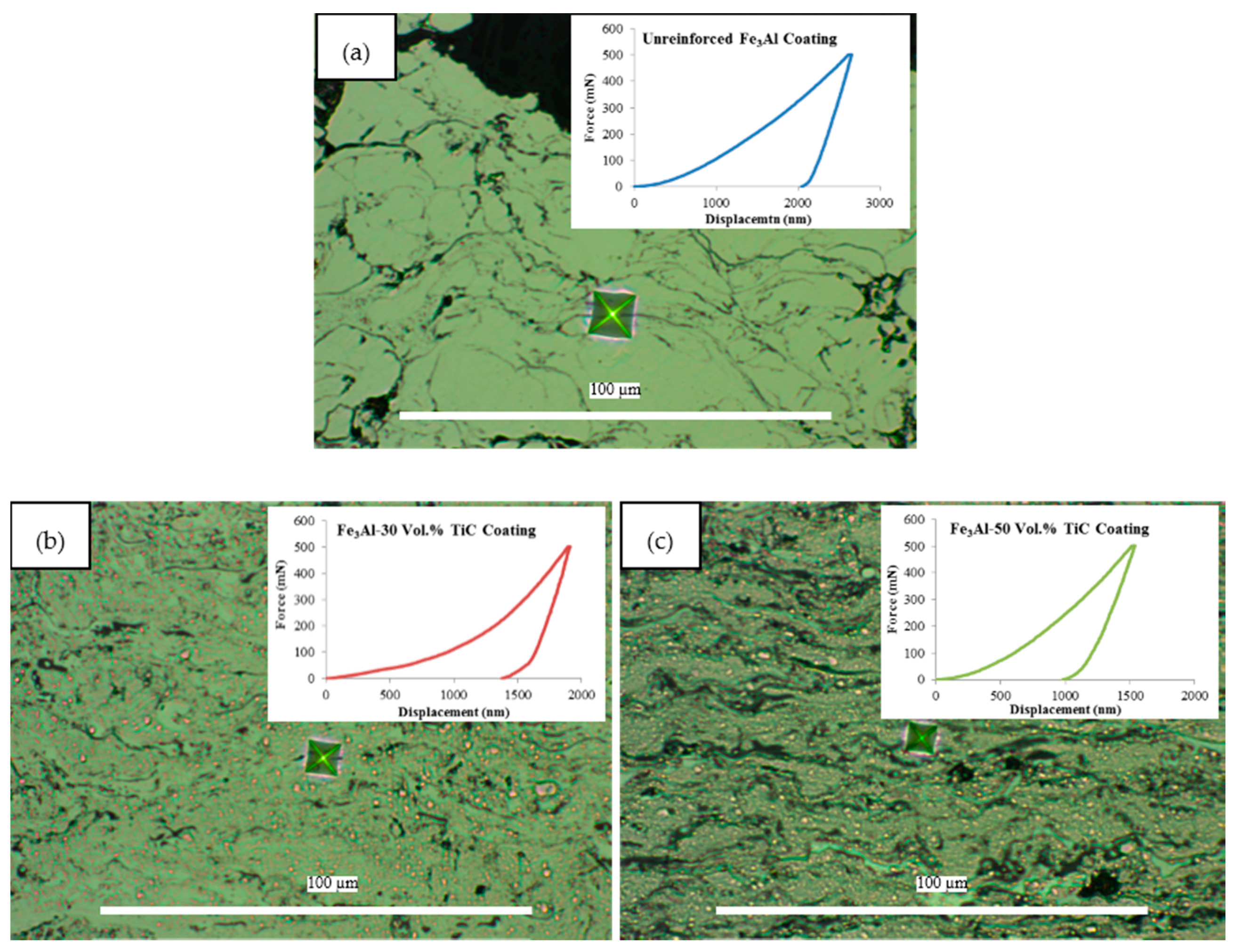
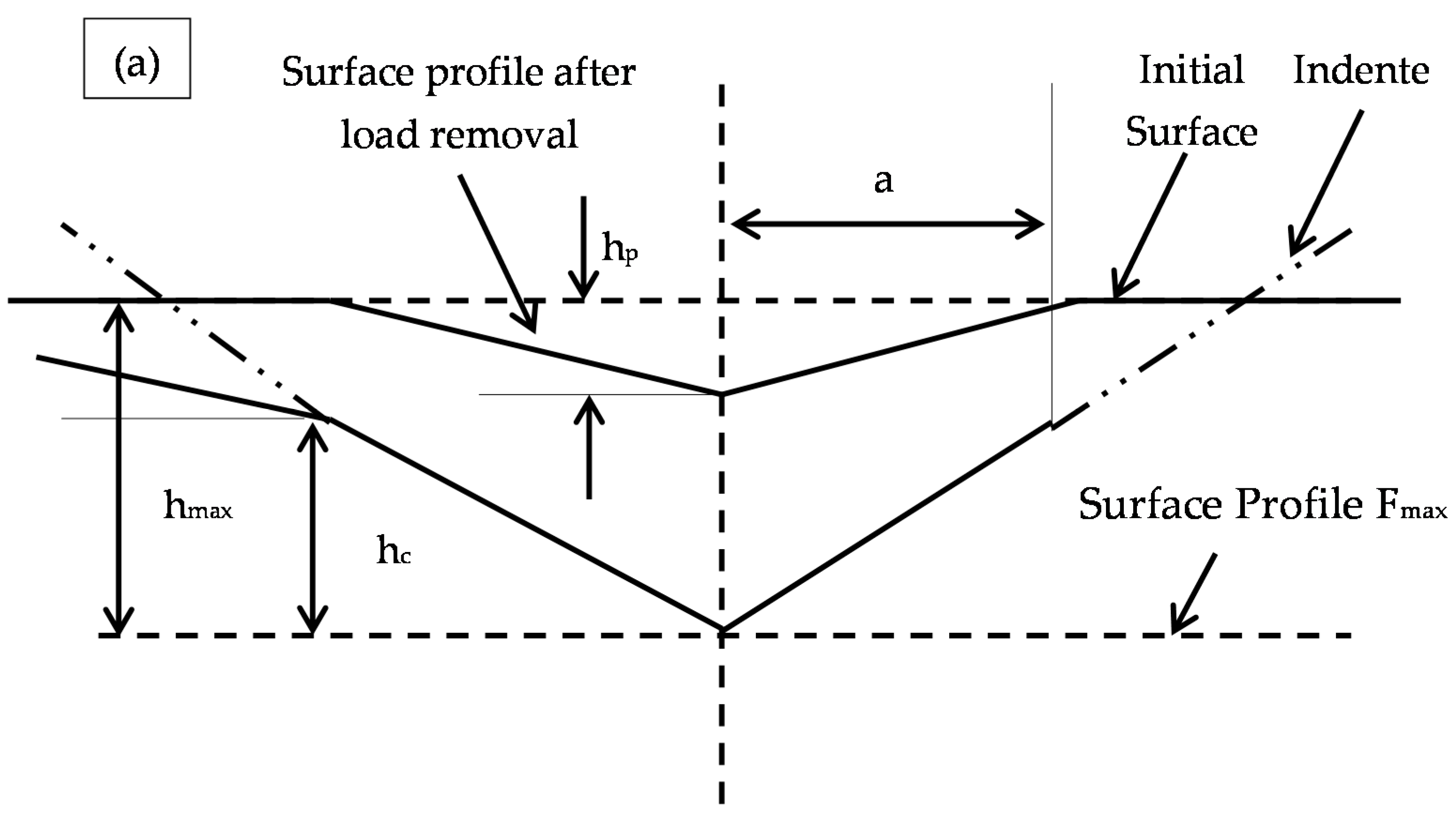
Figure 6 shows microindentation traces for each sample as well as their corresponding force-displacement curves. The size of the indentation trace is getting smaller as the TiC fraction increases. The force-displacement curves also show a smaller displacement for the samples with higher TiC loadings. A schematic representation of indenter-sample contact cross section is illustrated in Figure 7a. A graphical view of load-displacement data is also presented in Figure 7b, which defines experimental quantities involved in the hardness and elastic modulus measurements using the microindentation method.
With the addition of TiC particles into the coating microstructure, maximum indentation depth (hmax) drops, indicating a considerable raise in the hardness of the samples. On the other hand, the results showed that the composite coatings have higher elastic modulus than the unreinforced Fe3Al coatings. The hardness (H) and effective elastic modulus (Eeff) can be calculated from the load-displacement data, as follows,
and
where Fmax is the maximum load, A is the contact area after the indentation and β is a constant which depends on the geometry of the indenter (1.012 for a square shape trace [11]). The effective modulus, which accounts for the fact that during the indentation, elastic deformation occurs in both the indenter and the specimen, is given by Equation (4),
where Ei and νi are the Young’s modulus and Poisson’s ratio for the indenter (for diamond indenter, Ei = 1141 GPa and νi = 0.07 [14]), and E and ν are the same quantities for the sample. According to Equation 3, contact area and E have an inverse relationship.
H = Fmax/A,
Eeff = (√π × S)/(2 × β × √A),
Table 2 shows the resulting microhardness and elastic modulus of the coatings obtained from the force-displacement curves. Thus, it is obvious that the incorporation of TiC particles not only increases the hardness but also has a significant effect on increasing the elastic modulus of the sample. Similar results on the effect of titanium diboride particles on properties of the Fe–Al system have been reported [8,15].
The coefficient of friction (CoF) and dry sliding wear rates of the coatings were both measured in this study. However, CoF of the samples were between 0.8–1.0 and this does not seem to follow the trend of hardness or wear rates. Table 2 also presents the sliding wear rates of the coatings. It is seen that the wear resistance of the coatings increases with increasing TiC content most likely because of the high hardness of TiC particles (2900–3200 HV). Unreinforced iron aluminide coating exhibits the highest wear rate (1.5 × 10⁻³ mm3·N−1·m−1), while with 30 vol. % of TiC addition, the wear rate of the composite is significantly reduced to approximately 4 × 10⁻⁶ mm3·N−1·m−1. The wear rate decreases a little more when the volume fraction of TiC particles increases from 30 to 50 vol. %. For the coatings made from unreinforced Fe3Al, the alumina counterpart can easily penetrate the coating during sliding, resulting in significant material losses from the surface. In the Fe3Al–TiC composite coatings, the material removal is reduced due to the presence of TiC particles, which protect the matrix during sliding. It seems that this protection is very efficient with 30 vol. % of reinforcing particles but a further increase to 50 vol. % does not improve wear resistance significantly.
Researchers have discussed the relationship between wear rate and elastic modulus (E) in sliding wear [16]. This is not surprising since higher elastic modulus results in a smaller contact area between the counterpart and the coating. At the same time, materials with high elastic modulus often exhibit high harnesses as well [11]. Therefore, the consideration of both hardness and elastic modulus is important in order to explain the tribological behavior of a coating.
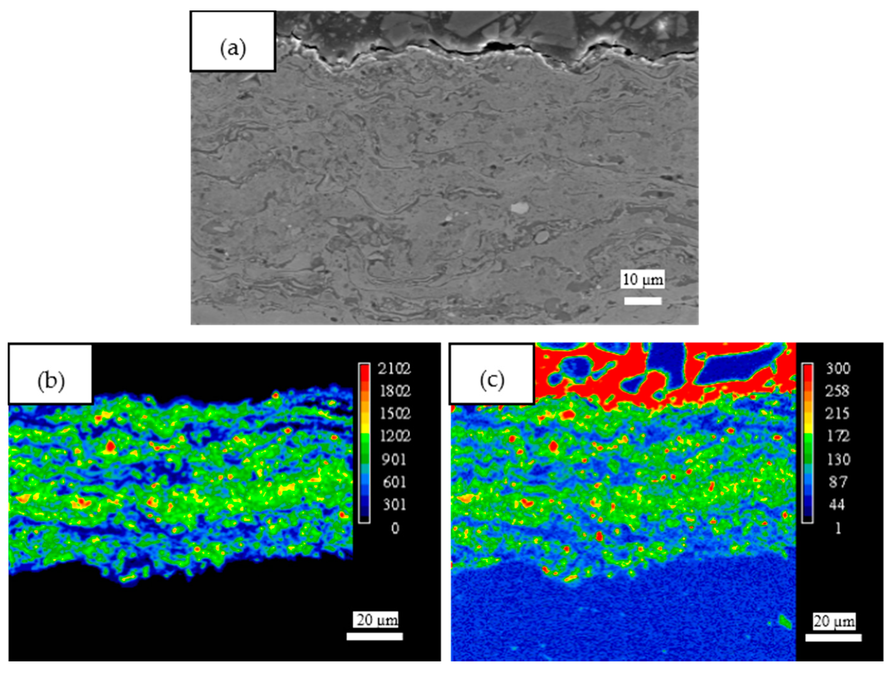
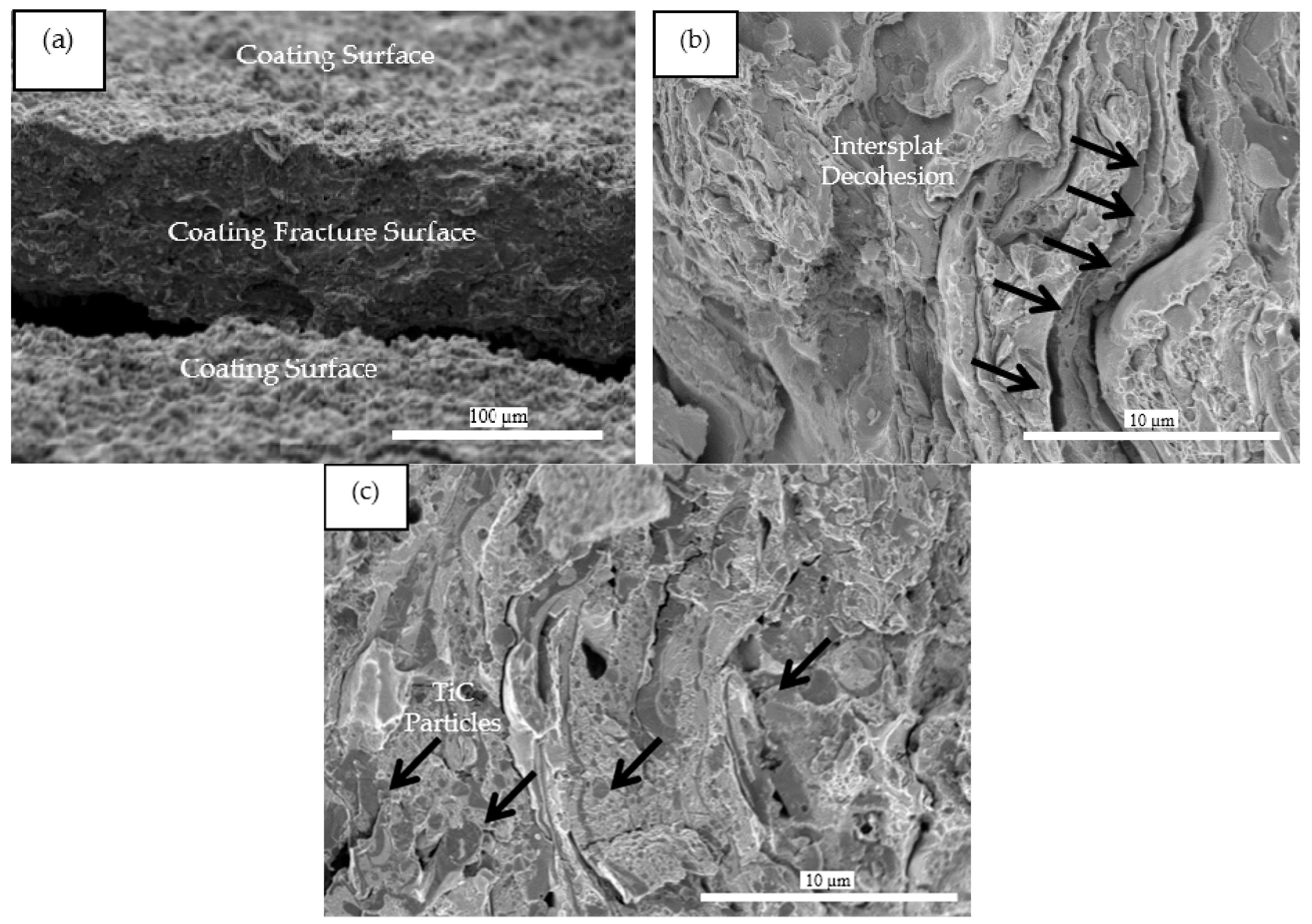
To further investigate the behavior of TiC particles within the composite coatings and their possible contribution to the wear resistance, the coated samples were fractured at room temperature (along with the substrate) using a bending setup. The SEM images of the fractured surface of the unreinforced and 50 vol. % TiC composite coating are shown in Figure 8. Figure 8a shows a low magnification image of a fractured coating, generated by the bending test. Figure 8b,c show the fracture surfaces at higher magnification for unreinforced and composite samples. A lamellar structure, which is characteristic of thermally sprayed coatings [7,8], is found in both samples. TiC grains, surrounded by the matrix, are clearly observed in the composite coating (see arrows in Figure 8c). However, it was found that there were distinct differences in the microstructural features of the two fractured coatings. Figure 8b shows that the unreinforced coating is more plastically deformed, has numerous cracks and to some extent, has a porous structure, which could affect crack propagation during the wear tests [17]. In this case, material removal occurs largely by the delamination of splats in combination with the plastic deformation, as evidenced by the fracture surface profile of the coating [18]. Significantly fewer cracks are observed in the fractured surface of the TiC-reinforced coating (Figure 8c). The reinforced coating shows a more uniform fractured surface with the TiC particles fully integrated within the matrix. Arrows in Figure 8c show examples of interfaces between Fe3Al and TiC. This is also evidenced in Figure 9, which suggests that the TiC particles are very well bonded to the matrix. It should be mentioned that matrix-particle detachment may or may not be revealed at higher resolution studies such as TEM analyses. In Figure 9, some TiC particles remain bonded to the matrix even after the fracture. As the projection conditions were the same for all samples, it seems that in addition to providing higher hardness and rigidity, the presence of cohesive TiC particles reduces the delamination of the coating by limiting crack propagation within the structure during wear tests. In Figure 9 one might also observe a mixed ductile (presence of dimples) and cleavage fracture in the presence of TiC particles in the composite coating. The superior properties of the Fe3Al–TiC coatings are thus a result of this strengthening phenomenon.
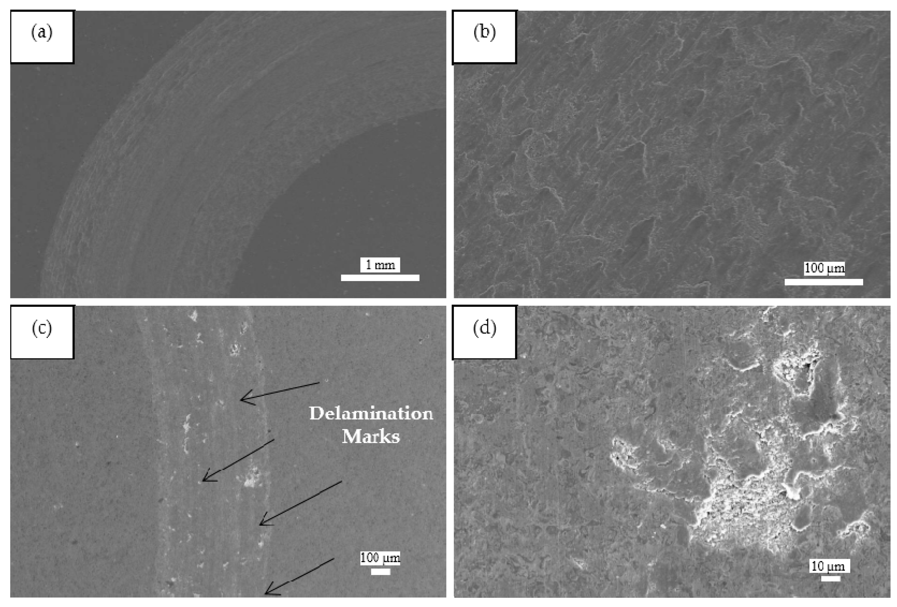
Figure 10 shows microscopic images of the surface of coatings with wear tracks. A much wider and deeper wear track profile is observed for the unreinforced iron aluminide coating. In other words, it is observed that the wear track of the composite coatings has a remarkably smaller width with considerably less depth. Different magnifications in Figure 10a,c were selected to reveal details in the wear tracks. Figure 10 also presents the worn surfaces of the coatings at higher magnification (Figure 10b,d). The worn surface topographies indicate that the dominant wear mechanism for the unreinforced Fe3Al coatings is different from that for the composite Fe3Al–TiC coatings. This is in agreement with the findings that have been reported for other thermal spray composite coatings [19,20]. Since the hardness of the alumina ball (2000 HV) is much higher than that of the Fe3Al matrix (≈300 HV), the wear marks on the unreinforced sample have been created by the plowing action of the alumina counterpart during the wear test, leading to significant delamination. Conversely, it can be seen from Figure 10d that only a few delamination marks appear on the worn surfaces of Fe3Al–TiC composite coating. The reinforcing particles are detectable on the top surface of the coating after sliding, indicating that they are well bonded to the matrix. When the retained TiC particles are well anchored into the matrix, they prevent the removal of the soft matrix by micro-cutting mechanisms, as observed in other composite materials [21]. It is thus evident that the TiC particles effectively protect the aluminide matrix and limit the material removal by the Al2O3 counterpart.
4. Conclusions
Wear-resistant iron aluminide composite coatings were fabricated by HVOF projection of milled Fe3Al–TiC powder particles. There were no undesired phases (e.g., oxide or complex decomposed carbides), confirming the fact that the HVOF parameters had been well chosen and no chemical reaction had occurred during deposition. The coatings have a dense microstructure consisting of well-bonded TiC particles within a Fe3Al matrix. Compared with the unreinforced Fe3Al coating, the Fe3Al–TiC composites have a much superior hardness and wear resistance. Incorporation of TiC particles resulted in hardness increase of about three times and consequently the wear resistance increased by three orders of magnitude. A volume fraction of 30% of TiC was found to be sufficient to obtain good wear resistance properties. Increasing the TiC volume fraction from 30% to 50% had marginal effects on tribological properties. Microscopic examination of the fractured surfaces revealed that the TiC particles are well bounded to the matrix and do not detach from the matrix. The improvement in wear resistance is believed to be related to the high hardness and elastic modulus, which in turn is due to the presence of well-bonded TiC particles in the Fe3Al matrix.
Acknowledgments
The authors wish to acknowledge the kind contribution of the technicians of the Department of Mining, Metallurgical and Materials Engineering of Laval University and Hydro-Quebec Research Institute. The financial support of this project was provided by Hydro-Quebec, Weir Canada and the Natural Sciences and Engineering Research Council of Canada (NSERC).
Author Contributions
Mahdi Amiriyan conducted the research under the supervision of Houshang Alamdari and Robert Schulz. Carl Blais and Mario Gariépy made comments during the research activities. Sylvio Savoie helped with thermal spray deposition and some the experiments.
Conflicts of Interest
The authors declare no conflict of interest.
References
- Stoloff, N.S. Iron aluminides: Present status and future prospects. Mater. Sci. Eng. A 1998, 258, 1–14. [Google Scholar] [CrossRef]
- Stoloff, N.S.; Liu, C.T. Environmental embrittlement of iron aluminides. Intermetallics 1994, 2, 75–87. [Google Scholar] [CrossRef]
- Liu, Y.; Cheng, J.; Yin, B.; Zhu, S.; Qiao, Z.; Yang, J. Study of the tribological behaviors and wear mechanisms of WC-Co and WC-Fe3Al hard materials under dry sliding condition. Tribol. Int. 2017, 109, 19–25. [Google Scholar] [CrossRef]
- Xu, B.; Zhu, Z.; Ma, S.; Zhang, W.; Liu, W. Sliding wear behavior of Fe-Al and Fe-Al/WC coatings prepared by high velocity arc spraying. Wear 2004, 257, 1089–1095. [Google Scholar] [CrossRef]
- Subramanian, R.; Schneibel, J.H.; Alexander, K.B.; Plucknett, K.P. Iron aluminide-titanium carbide composites by pressureless melt infiltration-Microstructure and mechanical properties. Scr. Mater. 1996, 35, 583–588. [Google Scholar] [CrossRef]
- Zhu, Z.X.; Du, Z.Y.; Xu, B.S.; Ma, S.N.; Zhang, W. Influence of heat treatment on microstructure and sliding wear behavior of Fe-Al/WC composite coatings. Trans. Tianjin Univ. 2003, 9, 93–97. [Google Scholar]
- Amiriyan, M.; Alamdari, H.D.; Blais, C.; Savoie, S.; Schulz, R.; Gariépy, M. Dry sliding wear behavior of Fe3Al and Fe3Al/TiC coatings prepared by HVOF. Wear 2015, 342–343, 154–162. [Google Scholar] [CrossRef]
- Amiriyan, M.; Blais, C.; Savoie, S.; Schulz, R.; Gariépy, M.; Alamdari, H. Tribo-Mechanical Properties of HVOF Deposited Fe3Al Coatings Reinforced with TiB2 Particles for Wear-Resistant Applications. Materials 2016, 9, 117. [Google Scholar] [CrossRef]
- Zhang, X.; Ma, J.; Yang, J.; Bi, Q.; Liu, W. Dry-sliding tribological behavior of Fe–28Al–5Cr/TiC composites. Wear 2011, 271, 881–888. [Google Scholar] [CrossRef]
- Pougoum, F.; Schmitt, T.; Martinu, L.; Klemberg-Sapieha, J.E.; Savoie, S.; Schulz, R. Wear behavior of Fe3Al-TiN-TiB2 HVOF coatings: A comparative study between in situ and ex situ powder processing routes. Ceram. Int. 2017, 43, 8040–8050. [Google Scholar] [CrossRef]
- Leyland, A.; Matthews, A. On the significance of the H/E ratio in wear control: A nanocomposite coating approach to optimised tribological behaviour. Wear 2000, 246, 1–11. [Google Scholar] [CrossRef]
- Oliver, W.C.; Pharr, G.M. An improved technique for determining hardness and elastic modulus using load and displacement sensing indentation experiments. J. Mater. Res. 1992, 7, 1564–1583. [Google Scholar] [CrossRef]
- Isalgue, A.; Fernandez, J.; Cinca, N.; Villa, M.; Guilemany, J. Mechanical and nanoindentation behavior of TiC–NiTi thermal spray coatings. J. Alloys Compd. 2013, 577, S277–S281. [Google Scholar] [CrossRef]
- Pharr, G.M. Measurement of mechanical properties by ultra-low load indentation. Mater. Sci. Eng. A 1998, 253, 151–159. [Google Scholar] [CrossRef]
- Xu, J.; Liu, W. Wear characteristic of in situ synthetic TiB2 particulate-reinforced Al matrix composite formed by laser cladding. Wear 2006, 260, 486–492. [Google Scholar] [CrossRef]
- Lancaster, J. The relationship between the wear of carbon brush materials and their elastic moduli. Br. J. Appl. Phys. 1963, 14. [Google Scholar] [CrossRef]
- Kim, Y.S.; Kim, Y.H. Sliding wear behavior of Fe3Al-based alloys. Mater. Sci. Eng. A 1998, 258, 319–324. [Google Scholar] [CrossRef]
- Pitchuka, S.B.; Boesl, B.; Zhang, C.; Lahiri, D.; Nieto, A.; Sundararajan, G.; Agarwal, A. Dry sliding wear behavior of cold sprayed aluminum amorphous/nanocrystalline alloy coatings. Surf. Coat. Technol. 2014, 238, 118–125. [Google Scholar] [CrossRef]
- Guan, X.; Iwasaki, K.; Kishi, K.; Yamamoto, M.; Tanaka, R. Dry sliding wear behavior of Fe–28Al and Fe–28Al–10Ti alloys. Mater. Sci. Eng. A 2004, 366, 127–134. [Google Scholar] [CrossRef]
- Yang, J.; La, P.; Liu, W.; Xue, Q. Tribological properties of FeAl intermetallics under dry sliding. Wear 2004, 257, 104–109. [Google Scholar] [CrossRef]
- Alamdari, H.; Couture, A.; Fiset, M. The effect of nickel, silicon and austenite deep-freezing treatment on the microstructure and wear properties of high chromium white iron containing niobium. Int. J. Cast Met. Res. 1998, 11, 89–95. [Google Scholar] [CrossRef]
Figure 1.
Optical microscopic image of a misplaced microindentation trace on a pore.

Figure 2.
Schematic illustration of ball-on-disk tribotester.

Figure 3.
Scanning Electron Microscopic (SEM) images of the (a,b) milled 30 and 50 vol. % composite powders and (c) particle size distribution of the feedstock.
Figure 3.
Scanning Electron Microscopic (SEM) images of the (a,b) milled 30 and 50 vol. % composite powders and (c) particle size distribution of the feedstock.

Figure 4.
X-ray diffraction (XRD) patterns of the commercial starting powders and as-sprayed Fe3Al–TiC coatings.
Figure 4.
X-ray diffraction (XRD) patterns of the commercial starting powders and as-sprayed Fe3Al–TiC coatings.
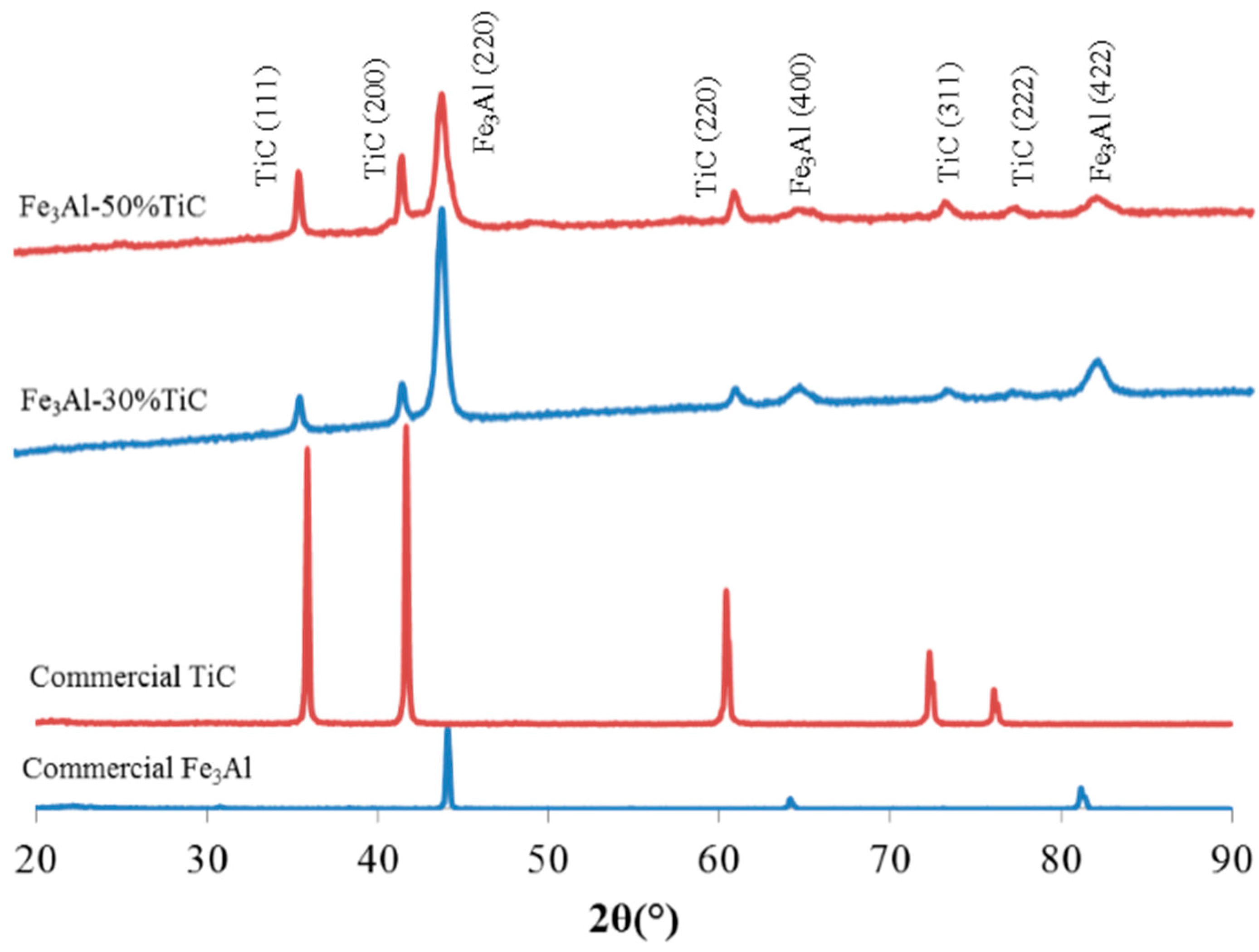
Figure 5.
(a) SEM back-scattered image and (b,c) mapping of titanium and carbon respectively.

Figure 6.
Microindentation images and load-displacement curves of (a) unreinforced Fe3Al, (b) Fe3Al–30 vol. % TiC and (c) Fe3Al–30 vol. % TiC.
Figure 6.
Microindentation images and load-displacement curves of (a) unreinforced Fe3Al, (b) Fe3Al–30 vol. % TiC and (c) Fe3Al–30 vol. % TiC.

Figure 7.
Schematic representation of indenter-sample contact cross section (a) and a graphical view of load-displacement data (b).
Figure 7.
Schematic representation of indenter-sample contact cross section (a) and a graphical view of load-displacement data (b).

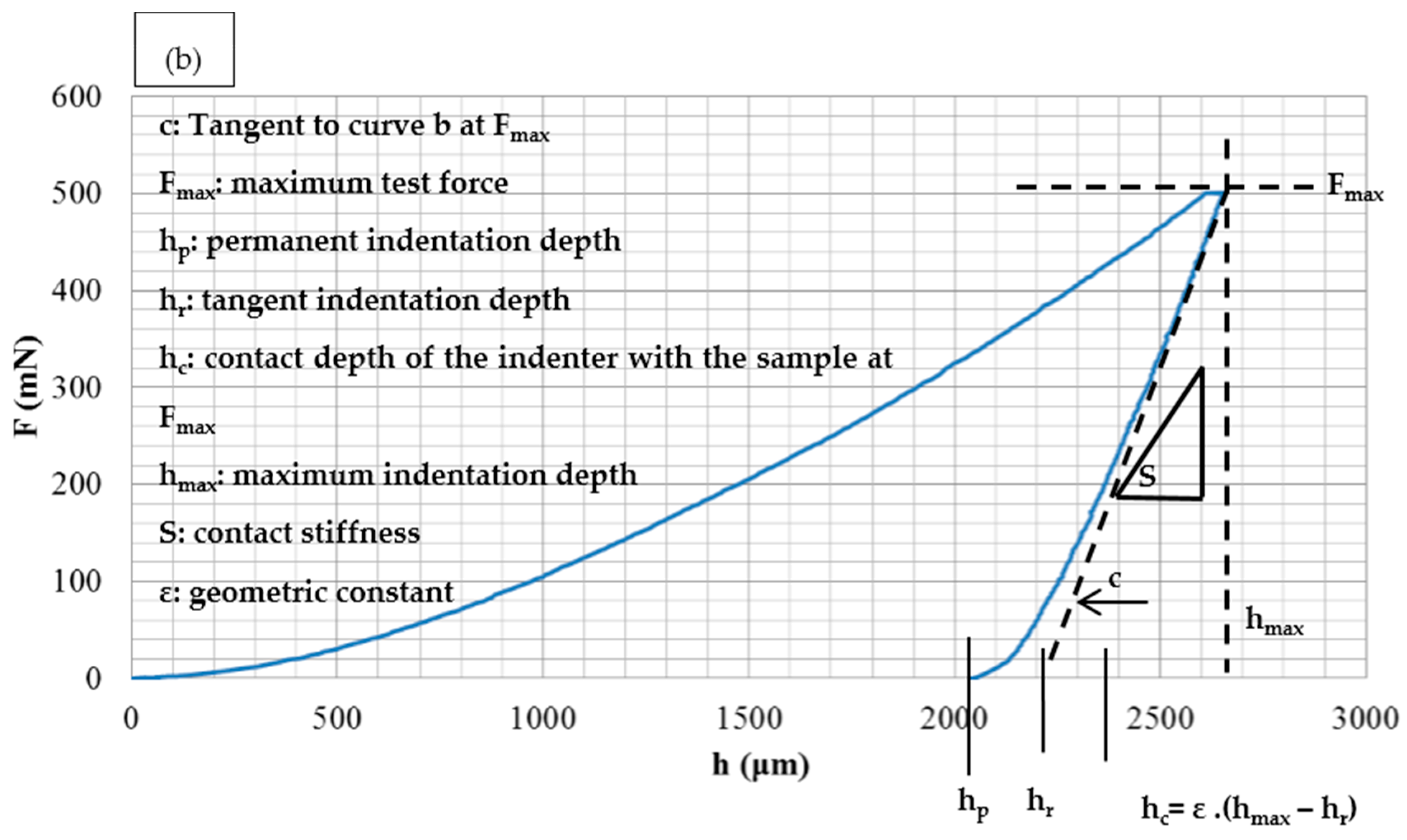
Figure 8.
Fracture surface SEM images of thermally sprayed coatings: (a) a general profile, (b) unreinforced Fe3Al and (c) Fe3Al–50 vol. % TiC sample. Arrows in b show large decohesion at splat interfaces. Arrows in c show well bonded TiC particles in the Fe3Al matrix.
Figure 8.
Fracture surface SEM images of thermally sprayed coatings: (a) a general profile, (b) unreinforced Fe3Al and (c) Fe3Al–50 vol. % TiC sample. Arrows in b show large decohesion at splat interfaces. Arrows in c show well bonded TiC particles in the Fe3Al matrix.

Figure 9.
Fracture surface SEM image of a Fe3Al–TiC coating showing TiC particles embedded in the matrix.
Figure 9.
Fracture surface SEM image of a Fe3Al–TiC coating showing TiC particles embedded in the matrix.
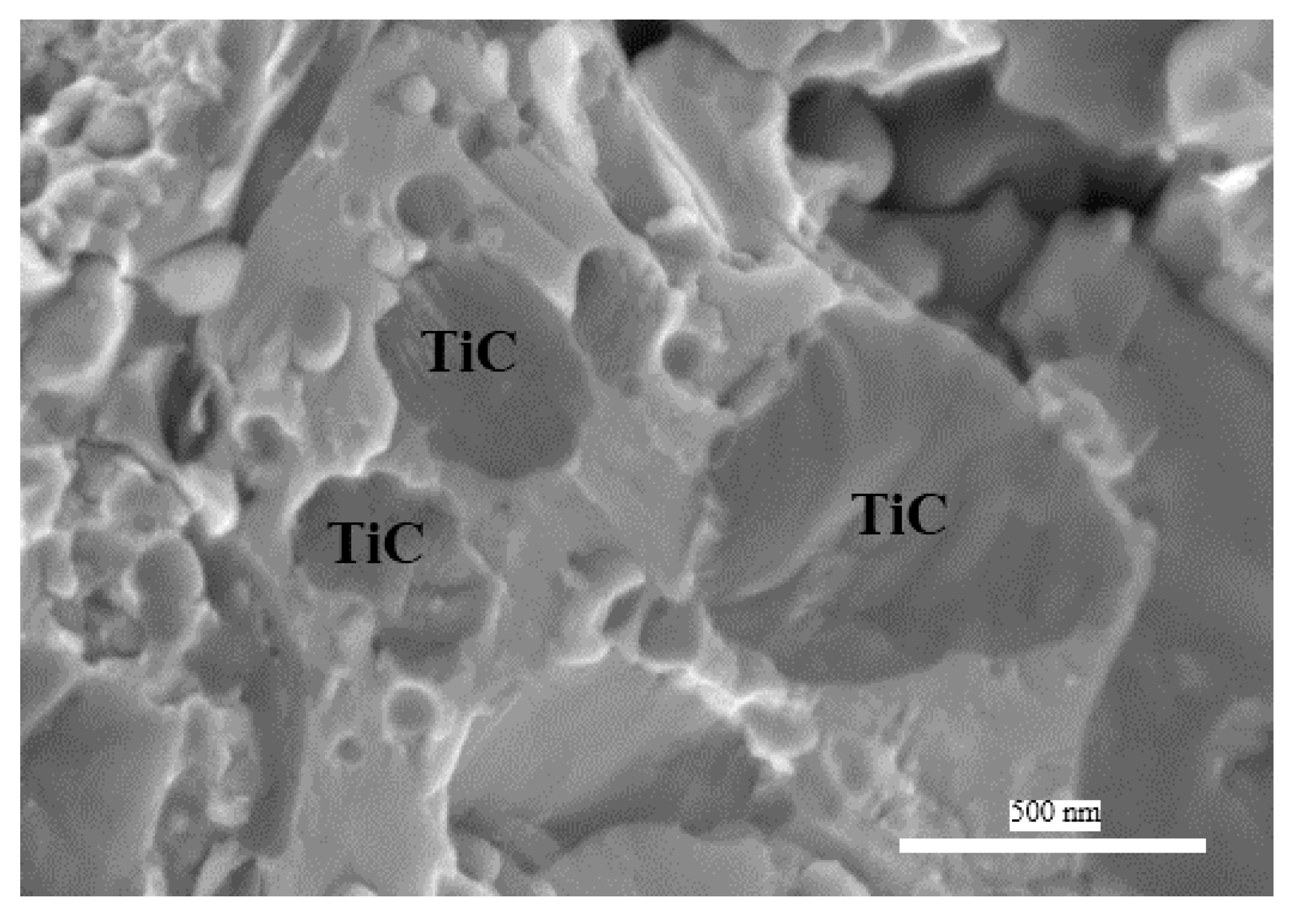
Figure 10.
SEM images of the sliding wear tracks of (a,b) unreinforced Fe3Al and (c,d) Fe3Al–50 vol. % TiC coatings. Arrows on (c) show some delamination marks.
Figure 10.
SEM images of the sliding wear tracks of (a,b) unreinforced Fe3Al and (c,d) Fe3Al–50 vol. % TiC coatings. Arrows on (c) show some delamination marks.


Table 1.
High-Velocity Oxy-Fuel (HVOF) projection parameters.
| Projection Parameters | Values |
|---|---|
| Robot arm velocity (mm/s) | 500 |
| Step size (mm) | 10 |
| Barrel length (mm) | 152.4 |
| Barrel diameter (mm) | 12.7 |
| Spraying distance (mm) | 380 |
| Powder feeder speed (rpm) | 6.6 |
| Oxygen flow rate (l/h) | 42,480 |
| Kerosene flow rate (l/h) | 23.47 |
| Carrier gas flow rate (l/h) | 566.3 |
| Carrying gas | Argon |
| Number of deposition passes | 10 |
Table 2.
Hardness, elastic modulus, and sliding wear rates of the coatings.
| Sample | Vickers Hardness (GPa) | Elastic Modulus (GPa) | Sliding Wear Rate, K (mm3·N−1·m−1) |
|---|---|---|---|
| Fe3Al | 3.1 ± 0.1 | 71.8 ± 1.5 | 1.53 × 10⁻³ ± 0.03 × 10⁻³ |
| Fe3Al/30 vol. % TiC | 8.9 ± 1.0 | 207.4 ± 2.2 | 3.99 × 10⁻⁶ ± 0.1 × 10⁻³ |
| Fe3Al/50 vol. % TiC | 10.7 ± 1.3 | 215.0 ± 3.5 | 3.52 × 10⁻⁶ ± 0.2 × 10⁻³ |
© 2017 by the authors. Licensee MDPI, Basel, Switzerland. This article is an open access article distributed under the terms and conditions of the Creative Commons Attribution (CC BY) license (http://creativecommons.org/licenses/by/4.0/).
Share and Cite
MDPI and ACS Style
Amiriyan, M.; Blais, C.; Savoie, S.; Schulz, R.; Gariépy, M.; Alamdari, H.D. Mechanical Behavior and Sliding Wear Studies on Iron Aluminide Coatings Reinforced with Titanium Carbide. Metals 2017, 7, 177. https://doi.org/10.3390/met7050177
AMA Style
Amiriyan M, Blais C, Savoie S, Schulz R, Gariépy M, Alamdari HD. Mechanical Behavior and Sliding Wear Studies on Iron Aluminide Coatings Reinforced with Titanium Carbide. Metals. 2017; 7(5):177. https://doi.org/10.3390/met7050177
Chicago/Turabian StyleAmiriyan, Mahdi, Carl Blais, Sylvio Savoie, Robert Schulz, Mario Gariépy, and Houshang D. Alamdari. 2017. "Mechanical Behavior and Sliding Wear Studies on Iron Aluminide Coatings Reinforced with Titanium Carbide" Metals 7, no. 5: 177. https://doi.org/10.3390/met7050177
Note that from the first issue of 2016, this journal uses article numbers instead of page numbers. See further details here.