
Laser Beam Welding of a Ti–6Al–4V Support Flange for Buy-to-Fly Reduction
by
 , , ,
, , ,
Fabrizia Caiazzo
1 ,
,
Vittorio Alfieri
1,*,
Gaetano Corrado
1,
Paolo Argenio
1,
Giuseppe Barbieri
2,
Francesco Acerra
3 and
Vincenzo Innaro
3 1
Department of Industrial Engineering, University of Salerno, Via Giovanni Paolo II 132, Fisciano 84084, Italy
2
Department of Sustainability, ENEA Casaccia, Via Anguillarese 131, Santa Maria di Galeria 00123, Italy
3
Department of Aerostructure Technology and Development, Leonardo Company S.p.A., Viale dell’Aeronautica snc, Pomigliano d’Arco 80038, Italy
*
Author to whom correspondence should be addressed.
Metals 2017, 7(5), 183; https://doi.org/10.3390/met7050183
Submission received: 12 April 2017
/
Revised: 5 May 2017
/
Accepted: 16 May 2017
/
Published: 20 May 2017
(This article belongs to the Special Issue Laser Welding)
Abstract
:Titanium and its alloys are increasingly being used in aerospace, although a number of issues must be addressed. Namely, in the framework of welding to produce complex parts, the same mechanical strength and a reduced buy-to-fly ratio are desired in comparison with the same components resulting from machining. To give grounds to actual application of autogenous laser beam welding, Ti–6Al–4V L- and T-joints have been investigated in this paper, as they are a common occurrence in general complex components. Discussions in terms of possible imperfections, microstructure, and microhardness have been conducted. Then, a real part consisting of a support flange for aerospace application has been chosen as a valuable test-article to be compared with its machined counterpart both in terms of strength and buy-to-fly. The feasibility and the effectiveness of the process are shown.

1. Introduction
New materials and methods are being tested for aerospace in order to meet the challenges of innovation and reduce operating costs, but extensive studies are mandatory before introducing any change in industrial environments, as strict standards apply. In this regard, mechanical assembly is generally preferred because a reduction in waste material is achieved compared with its machined counterpart; this trend leads to shorter lead times and lower buy-to-fly ratio (i.e., the weight ratio between the amount of raw material to manufacture a component and the amount of the final part) [1]. Namely, improvements at the design stage are aimed to remove any mechanical fastening, such as screwing and riveting to introduce welded assemblies, thus preventing any increases in thickness.
Laser beam welding (LBW) is regarded as the logical solution to accomplish these different needs, as a number of benefits are provided in comparison with conventional welding technologies [2,3]. For instance, the process can be performed in remote locations and over three-dimensional components from single side access [4], autogenously and generally with no need for post-processing such as mechanical finishing; increased processing speed is achieved, and as a consequence, productivity is improved [5]. Advantages come from the primary feature of narrowly focusing the heat source; deep penetration is achieved when performing the process in key-hole mode, thus focusing the beam energy where required, preventing overheating of the base metal, which would suffer from thermal distortion and degradation of metallurgical properties otherwise [6].
A number of papers are available in the literature dealing with LBW of titanium alloys, which are widely used in aerospace thanks to high strength in combination with low density and good tensile properties; medical and surgical devices are even produced thanks to high biocompatibility [7]. Given these reasons, Ti–6Al–4V accounts for more than half of all titanium tonnage in the world and no other titanium alloy is deemed to threaten such a dominant position [8]: it is normally and extensively employed for turbine disks, compressor blades, airframe and space capsule structural components, rings for jet engines, pressure vessels, rocket engine cases, helicopter rotor hubs, fasteners, and engine exhausts [9]; thick titanium plates of up to 16 mm, for seagoing vessels and submarines, are even welded by means of LBW in the maritime industry [10].
In comparison with traditional technologies, tight laser beams have been proved to be effective in reducing both angular distortion and longitudinal bending on thin sheets [11]. Furthermore, a reduced mean grain size in the fusion zone is achieved; the overall mechanical quality is hence improved, considering that the grain growth is deemed to be one of the reasons for the reduction of tensile strength upon welding [12]. On the other hand, a significant reduction in ductility may occur due to aluminum oxides and micro pores. Provided that inert shielding is accomplished for the purpose of bead protection to produce sound joints and prevent oxidation [13], it has been shown that as few as 2% total porosity implies an 85% decrease in the ultimate tensile strength of the joint with respect to the base metal [12]; moreover, due to the specific evolution of the thermal fluid flow, porosity is found to occur mainly when the fusion zone is only partially penetrating through the thickness of the material [14]. In this way, uniform flow in the welding pool can be driven by the shielding gas, when the diameter of the key-hole is made larger and more stable [15].
A reduction of the mechanical properties may also result from non uniform fusion and geometry imperfections such as undercut and shrinkage groove [16] in the cross-sections, although a reliable predictive model to assess the extent of these as a function of the processing parameters has been proven to be unfeasible [13], as for other metal alloys [17]. Therefore, wire feeding [18] or hybrid welding with an assisting gun [19] are considered the usual practice to prevent imperfections.
Changes in the base microstructure and microhardness are produced as a consequence of welding. The parent metal is a two phase allotropic alloy [9]: the typical annealed microstructure consists of α hexagonal close-packed matrix with a body-centered cubic β phase at grain boundaries. A non–diffusional transformation into a martensitic α’ microstructure is induced upon welding and cooling [8,20], hence the resulting hardness of the fusion zone is increased with respect to the parent metal [21]. Namely, a remarkable increase in the order of even 140 HV normally occurs in the fusion zone, although no clear trends in the mean value are reported as a function of the welding speed [8].
In order to improve ductility and fatigue properties in the fusion zone, post-welding heat treatment is required [22,23]. It has been reported in the literature [24] that full annealing of welds at 700 °C for 2 h results in improved fracture toughness in the operating range from room temperature to 500 °C, with a moderate decrease of hardness (i.e., from 361 to 356 HV on average) in the fusion zone.
To provide further understanding of LBW of Ti–6Al–4V and to provide valuable insight to be used in real parts, a number of tests are discussed in this paper relating to both L-joint (i.e., corner joint, fillet joint ) and T-joint (i.e., right-angled joint), as both of them occur commonly in general complex components. The processing window has been set, then the outcome in terms of deviations from the intended geometry, the microstructure and the microhardness has been discussed. Furthermore, a proper test-article for aerospace application has been chosen, welded and tested to assess the effectiveness of LBW on actual components where multiple welds are required. Namely, welding, destructive and non destructive testing on a support flange have been conducted; a comparison has been drawn with the machined counterpart and the improvement in terms of buy-to-fly ratio has been eventually discussed.
2. Materials and Methods
2.1. Process Set-Up
To set the processing window, L- and T- joints (Figure 1) have been investigated; 3 and 5 mm thick plates have been considered. The welding set-up to access the joints with the laser beam has been chosen to comply with usual customer regulations in aerospace, since uniform complete penetration is mandatory and transparent welding, as investigated before [25], is not allowed. As a consequence, a proper approaching angle α of the laser beam to access the joint from inside must be considered. Furthermore, in view of shifting the results on a real component and given the need for combined, integrated clamping and effective inert shielding of the welding bead (i.e., top- and back-side shielding), autogenous welding has been considered; additional complex and expensive devices for wire feeding or hybrid welding would be required otherwise, whereas proper room for managing the laser head along the welding path on the test-article is crucial.
Although widespread research has been conducted with the same laser source on the same alloy on square butt joints [13,26], a convenient adjustment of the processing window has been required to comply with the current geometry. Irrespective of the joint type, the laser beam nominal power has been taken as a constant, 6 kW in continuous wave operation mode; a focused beam has been delivered to the theoretical interface. As regarding the L-joint, the effect of welding speed has been investigated; the beam angle to approach the joint has been taken as a constant, 25°, with respect to the 5 mm thick plate. In regards to the T-joint, a fully penetrative bead must be obtained by means of two welding passes, one pass at each side of the joint, each pass being partially penetrative (Figure 2); hence the welding speed has been conveniently adjusted (i.e., increased) with respect to the L-joint and the approaching angle α has been investigated for the purpose of uniform fusion along the interface. A recap of the processing conditions to be tested on sample joints is given in Table 1.
Positions of the devices to perform laser beam welding (LBW) on the specimens is a carryover of a patent [27]. With respect to the direction of welding, a leading nozzle and helium supplying has been used for metal plasma blow. A trailing diffuser has been considered for argon shielding of the top surface of the welds instead. Shielding of the root in case of fully penetrative welding on L-joints has been accomplished by means of additional argon supply via a grooved box. Based on preliminary trials, a flow rate of 10 L/min has been set for assisting helium, whereas the argon flow for the surface and root has been set to 50 and 30 L/min, respectively.
Prior to welding, the samples have been manually polished with abrasive grinding paper, then degreased. LBW has been performed using a Yb:YAG fiber laser source (IPG Photonics, Oxford, MI, USA), whose main technical features are given in Table 2; three specimens have been processed for each welding condition. A 735 °C, 120 min heat treatment has been conducted in vacuum on the welding beads (TAV Vacuum Furnaces, Caravaggio, Italy) to the purpose of stress relieving. Inspections in three cross-sections coming from each weld have been conducted upon chemical etching with a solution of hydrofluoric acid (48%, 10 mL), nitric acid (65%, 15 mL), and water (75 mL) at room temperature. Vickers microhardness testing (Zwick Roell, Ulm, Germany) has been performed to investigate the response of the material in terms of microstructure evolution; namely, an indenting load of 0.300 kgf has been used for a dwell period of 10 s; a 150 μm step has been allowed between consecutive indentations, in agreement with the usual international standards on Vickers testing [28].
2.2. The Test-Article
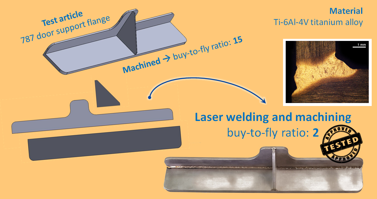
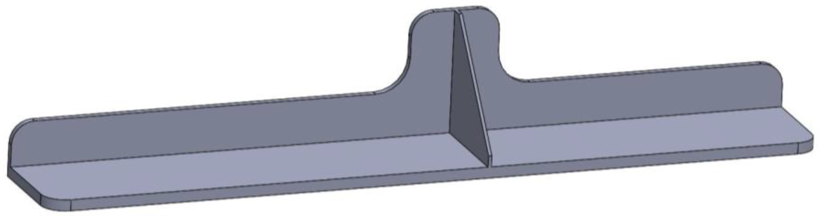
A Ti–6Al–4V support flange test-article (Figure 3) has been processed. The part is designed to be used where metals and composites are in place; to this purpose, titanium alloys are suggested thanks to better corrosion resistance with respect to aluminum. The specimen is composed of three parts, resulting from water-jet cutting (Waterjet Corporation, Monza, Italy) and post-process milling (EMCO GmbH, Hallein, Austria) of the abutting surfaces: a 5 mm thick cap-plate, a 3 mm thick web-plate and a 3 mm thick supporting rib (Figure 4). Both L- and T-joint are involved, the former to weld the cap-plate to the web-plate, the latter to weld the rib, at its sides, with the web- and the cap-plate.
A proper method to prevent any possible deviation from the intended geometry must be taken into account to match specific customer regulations. Wire feeding or hybrid welding with an assisting gun are not fit to LBW of the test-article, as additional devices would be required in the system set-up. Therefore, for the purpose of easier automation and control of the actual process, increased thickness has been considered for the parts to be welded, 8 mm instead of 5 mm for the cap-plate, 5 mm instead of 3 mm for the web-plate and the rib: the driving idea is to perform machining by means of side and face milling upon welding in order to restore the nominal thickness of the test-article, thus removing any undercut and shrinkage groove concurrently. A significant favorable reduction of the buy-to-fly ratio is deemed to be achieved anyway with respect to machining from wrought metal and will be proven in the following.
Therefore, the welding parameters resulting from the experimental campaign (i.e., the process set-up) have been conveniently adjusted, so to effectively weld L- and T-joints of increased thickness (Table 3). Basically, the approaching angle and the power level have been taken, whilst the processing speed has been decreased. Nevertheless, in order to obtain deep penetrative welds, a 1 mm offset of the laser beam with respect to the theoretical welding line and towards the thinner plate has been required for L-joint configuration. Flow rates of assisting helium and argon supply have been taken as constant.
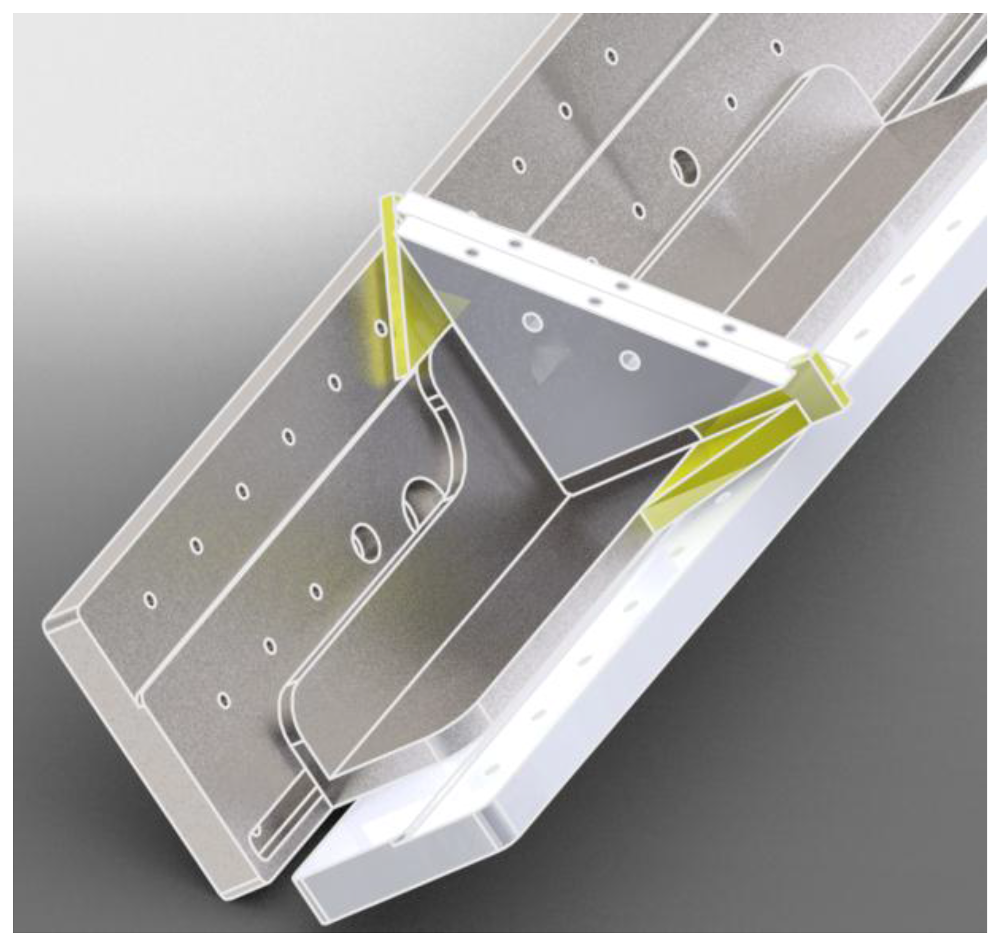
A non-commercial device to clamp the components of the test-article and concurrently provide inert shielding has been developed for the mere purpose of this research, consisting of two right-angled steel supports to accommodate the cap- and the web-plate, providing a hollow duct at their virtual intersection for the purpose of gas supply for back-side shielding. The cap- and the web-plate have been clamped using adjustable plain clamps (Figure 5); upon local spot welding with 100 mm step to better tighten the components to prevent unwanted slippage from the nominal position, LBW in L-joint configuration has been performed in a single pass with the suggested processing parameters and a 1 mm offset of the laser beam towards the web-plate with respect to the theoretical welding line (Figure 6) has been set. Assisting gases have been supplied: argon at back-side via the hollow duct on the clamping system, at top-side via the diffuser moving with the laser head; helium via the leading nozzle for metal plasma blow (Figure 7): a proper time delay has been allowed before welding to prepare inert atmosphere with stable inert flux; additional delay has been required to effectively shield the bead at laser switch-off.
The device to clamp the rib has been placed afterwards. An additional part is used to house, position, and concurrently shield the rib (Figure 8): a movable clamp allows tightening of the rib; shielding is supplied at both sides via separate ducts. Upon local spot welding to prevent unwanted slippage from the nominal position, LBW in T-joint configuration has been performed with two welding passes, one pass at each side of the joint, each pass being partially penetrative, with the suggested processing parameters. Helium has been supplied for top-side shielding; additional flow for metal plasma blow has not been arranged, the purpose being fulfilled by helium itself when leaving; argon has been supplied for back-side shielding against oxidation due to overheating, although full penetration is prevented.
Three test-articles have been welded (Figure 9), then heat treatment has been conducted, as for the samples in the process set-up. Machining by means of side and face milling has been performed to achieve the nominal thickness of the parts upon welding. In addition, ultrasonic non-destructive testing (GE Panametrics, Fairfield, United States, with custom interface developed by ENEA) have been performed to inspect the penetration depth.
3. Results and Discussion
3.1. Geometry
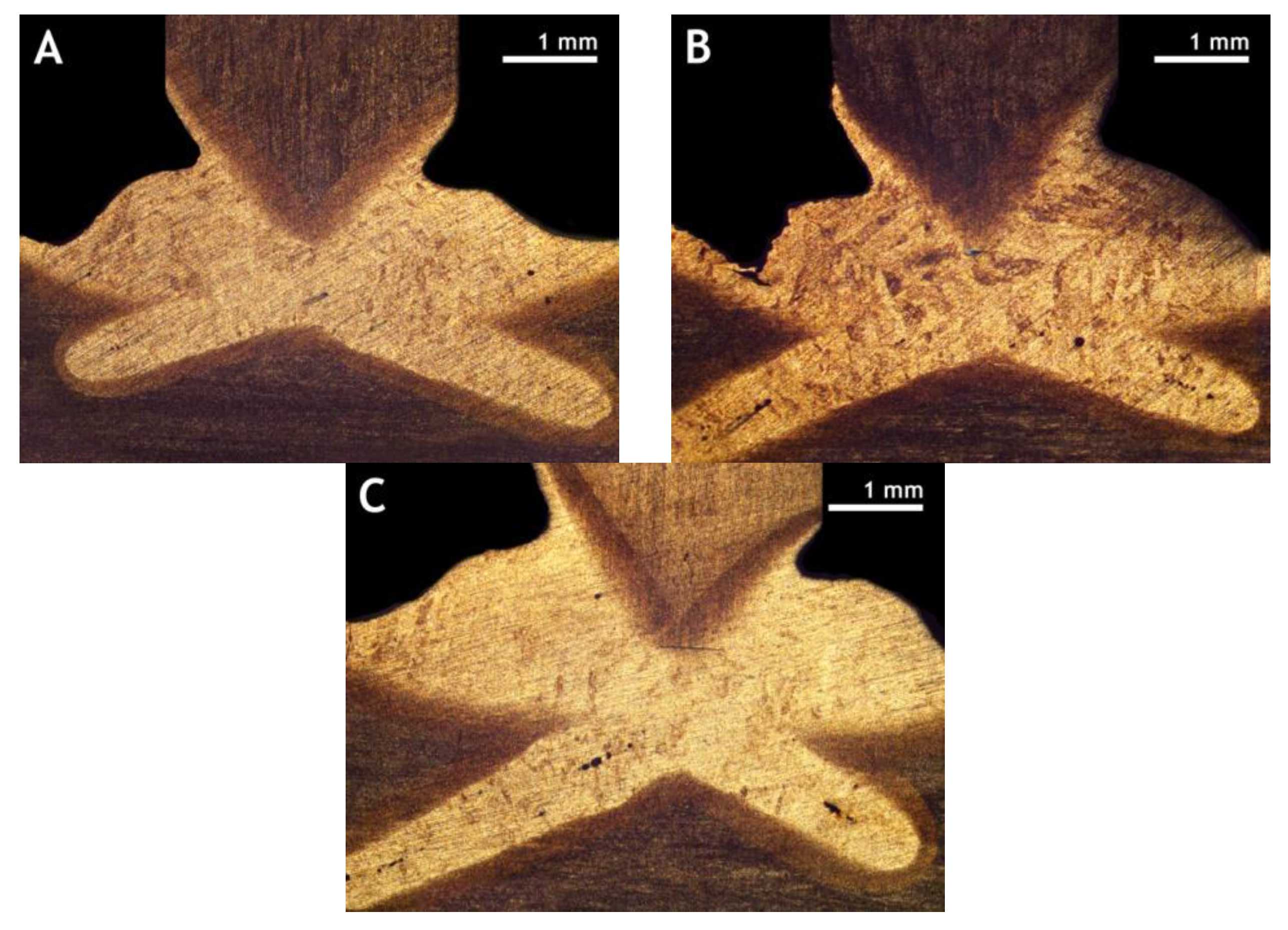
With respect to the L-joints, for a given approach angle of 25°, the effect of the welding speed has been discussed. Weldability is proven, although discontinuous joining at the interface of the abutting plates may occur for increasing welding speed (Figure 10). Therefore, as uniform fusion along the interface is mandatory for aerospace application of LBW, a welding speed of 2400 mm∙min−1 is thought to be adequate to perform the process.
With respect to the T-joints, uniform fusion of the interface between the abutting plates depends on the approach angle of the laser beam (Figure 11). A 20° angle is thought to be adequate to perform the process, irrespective of the thickness of the lower plate. For both the L- and the T-joints, imperfections in the cross-section for the suggested welding conditions have been found to comply with usual standards [29], although stricter customer regulations may not be matched, depending on the application. Hence, to address the issue of possible deviations from the intended geometry, a number of adjustments have been made when setting the experimental procedure for the test-article.
3.2. Microstructure and Microhardness
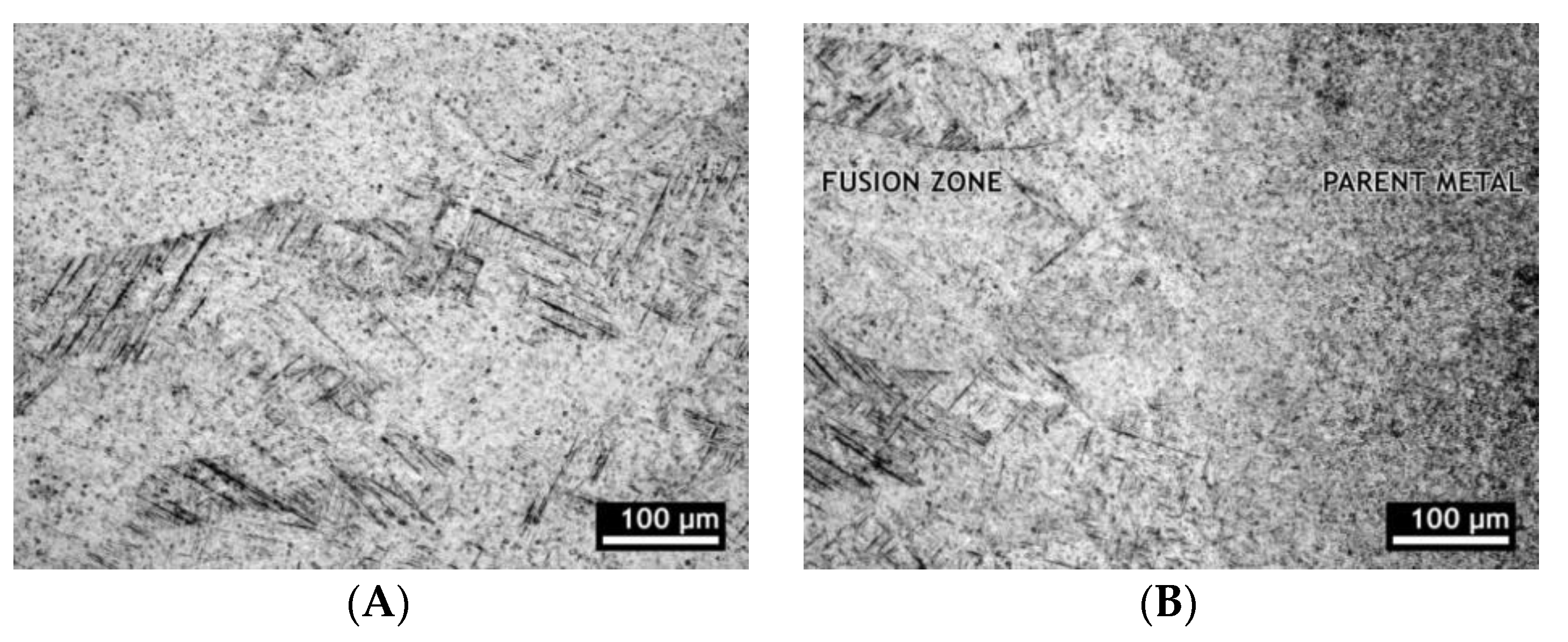
The evolution of the microstructure across the welding bead is worth investigating, as this would provide crucial information to discuss the response to loading. Prior to heat treatment, the original microstructure of the base metal has been lost in the fusion zone, a martensitic α’ microstructure has been induced (Figure 12A). A similar structure results when quenching from the β phase region above the β-transus temperature. The heat-affected zone has been found to be a mixture of α’ and primary α phase instead (Figure 12B), as matching a structure which is quenched from a region below the β-transus temperature. The grain size is affected by the welding speed, as shown via numerical models on the same alloy [13]: namely, any increase in the welding speed yields a decrease in the grain size, since the cooling rate is increased for the given power and defocusing.
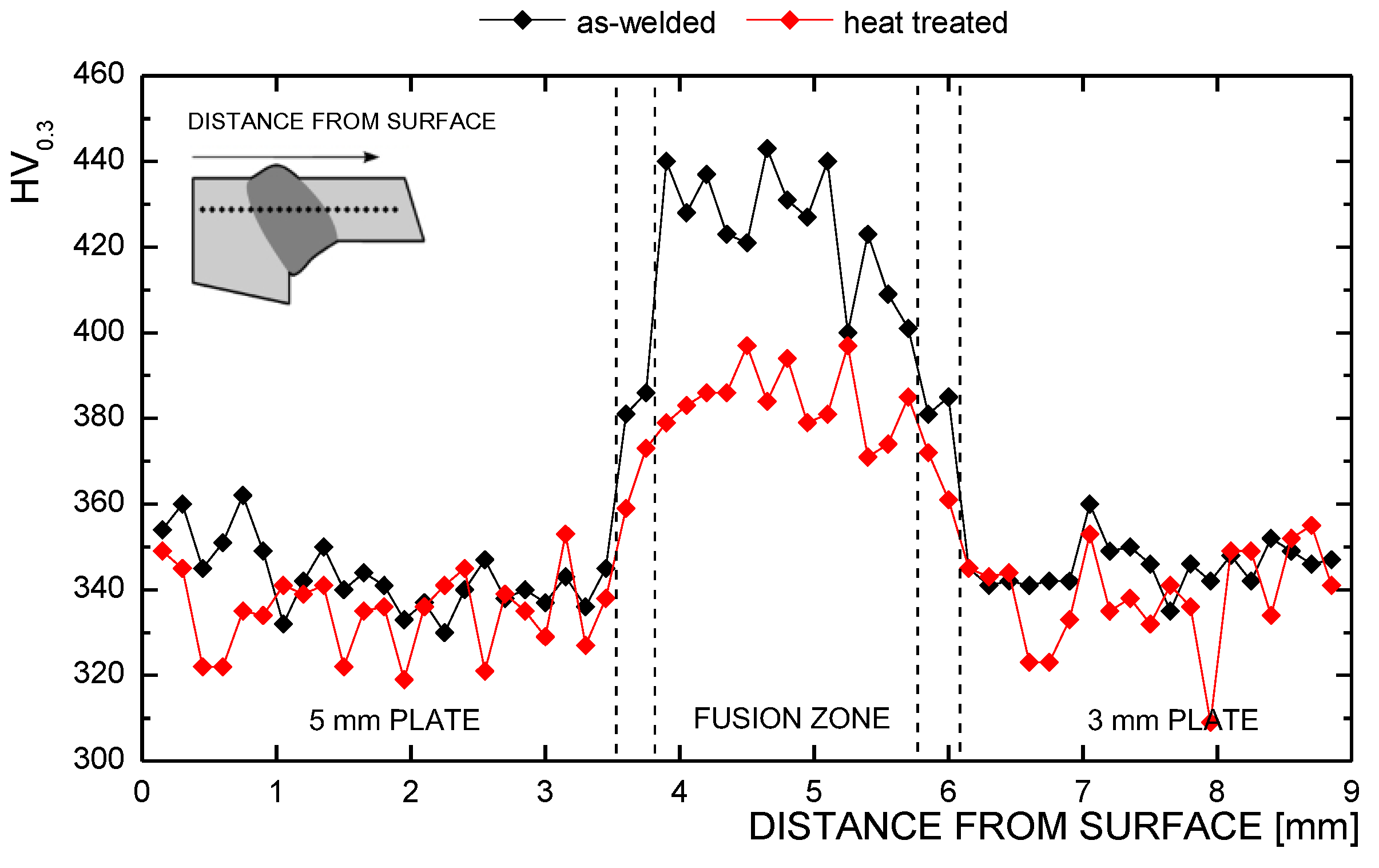
To further discuss the subject, the trend of Vickers microhardness in the cross-section has been investigated, both prior to and upon heat treatment (Figure 13). An increase of hardness resulted in the fusion zone, from 340 HV0.3 in the base metal to average 430 HV0.3 with as high as 443 HV0.3 peak values in the as-welded condition. In agreement with the literature [24], it is worth noting that a decrease of hardness to average 382 HV0.3 in the fusion zone, hence a reduced mismatch with respect to the base metal, has been benefited upon heat treating. Furthermore, based on the step between consecutive indentations (i.e., 150 μm), the extent of the heat-affected zone is deemed to be shorter than 0.3 mm at both sides of the fusion zone and is not considered to be affected by heat treatment. Similar trends have been found, both in L- and T-joint. As regarding the latter, the microstructure in the fusion zone resulting from the first welding pass is unaffected by the second pass [30], as new fusion and cooling are experienced with the same rates. It is worth noting that no clear trends in the mean value have been found as a function of the welding speed, in agreement with the literature [8], irrespective of the grain size, which is expected to affect the mechanical strength instead [12].
3.3. Testing of the Test-Article
Sound beads resulted along the L-joint between the cap- and web-plate; a number of indications to be ascribed to micro-pores have been detected when scanning T-joints instead (Figure 14). Imperfections are mainly located at the tip of the rib, as two welding beads cross; in terms of size and cumulated area, these are not deemed to affect the overall mechanical response.
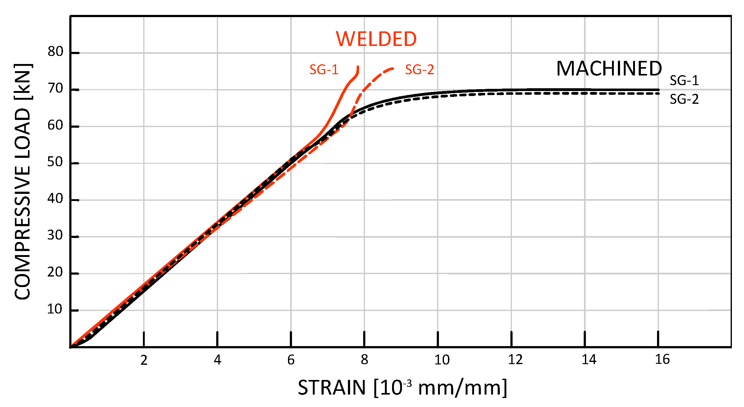
Drilling of the web-plate of the test-article has been performed in order to allow clamping on the static testing device which has been specifically developed and manufactured in order to accurately reproduce the nominal condition of stress of the test-article (Figure 15); the device has then been employed on a conventional tensile testing machine. Two strain gauges (SG–1 and SG–2), one for each side of the supporting rib (Figure 16), have been monitored. Three test-articles resulting from welding and three test-articles resulting from machining of wrought titanium have been tested.
Based on the application of the real component, the threshold to be matched has been set to 15 kN, which is intended to be the limit load; nevertheless, as no evidence of failure were found in the form of cracks for all of the specimens when approaching the threshold, testing has been further progressed until there was contact between the test-article and the device for testing.
The average strain as monitored by SG–1 and SG–2 at 10, 15, and 20 kN are given in (Table 4). The load-strain diagram resulting from testing of welded and machined test-articles have been compared (Figure 17). Interestingly, the same behavior has been found for the test-articles in the operating nominal loading window and up to 50 kN, irrespective of the processing technology; a difference has been found above 60 kN instead, where higher strain is experienced by the samples resulting from machining. Namely, welding is deemed to provide improved strength thanks to microstructural evolution upon processing, as discussed in the process set-up, based on Vickers microhardness testing, although reduced percent elongation resulted.
3.4. Improving the Buy-to-Fly Ratio
The net weight of the test-article as required for the actual application is approximately 1.05 kg. Three methods to produce the component are compared in the following in terms of buy-to-fly: machining from bulk, LBW of plates of increased thickness (i.e., 8 and 5 mm) with eventual machining to nominal size, LBW of plates of nominal thickness (i.e., 5 and 3 mm). Both the theoretical and actual buy-to-fly ratio have been evaluated. Namely, the theoretical buy-to-fly ratio has been measured based on the net weight and the expected allowance at the contour to cut each single part to be welded; the actual buy-to-fly ratio has been measured with additional metal allowance taken into account instead, as a consequence of mutual arranging of the parts on a larger metal sheet to be cut. Both of them are hence larger than 1, the latter being higher. Both the measures have been made for each processing method and are given in Table 5.
Saving of metal in a measure of at least 80% is benefited when considering LBW as an alternative to machining; moreover, a 50% reduction on the overall cost of the component results in the case of LBW with eventual machining to nominal size. Although additional cost saving would be expected from LBW of plates of nominal thickness to prevent machining, wire feeding or assisting gun for hybrid welding should be required to address the issue of geometrical imperfections such as undercut and shrinkage groove: costs have been found to remain the same, with limited actual gain, but proper managing of the welding paths would be prevented due to additional devices. Given this, the solution of LBW and machining to nominal size is deemed to offer a valid method to be shifted to any complex real part where L- and T-joints are usually required.
4. Conclusions
Grounds have been given for the application of LBW for the purpose of joining titanium parts for aerospace. Comparisons among laser beam welding and machining from bulk of a given test-article have been conducted: the same behavior in static testing under compressive loading has been found in the operating nominal loading window; moreover, improved strength resulted from welding. This must be ascribed to a non-diffusional transformation into a harder martensitic α’ microstructure upon processing, as proven by optical microscopy in combination with Vickers microhardness testing. Thermal treating has been required and performed to the purpose of stress relieving: the resulting microhardness in the fusion zone is not deemed to be affected, whereas an improvement in terms of fracture toughness is expected.
Given the thickness of the test-article, the ideal scenario to reduce the buy-to-fly ratio would have been joining 3 mm to 5 mm thick plates; wire feeding or hybrid welding would be required, resulting in critical managing of the laser head along the welding path due to additional devices. This issue is crucial and should be specifically addressed depending on the geometry of the test-article. Therefore, autogenous joining of parts of increased size would be desirable, with final machining upon welding. This approach has been considered with the test-article, and an actual buy-to-fly of 3.5, resulted on average a 50% reduction on the overall cost of the component as a further benefit. These findings are deemed to be reasonable for any complex component where a number of multiple welding passes are required, both on L- and T-joints.
Acknowledgments
The authors gratefully acknowledge the Italian Ministry for University and Research (MIUR) for funding this research activity through PON01_01269 ELIOS, as well as all the people, including students and referee, who contributed to the successful outcome of the research.
Author Contributions
Fabrizia Caiazzo, Giuseppe Barbieri and Francesco Acerra conceived and designed the experiments; Vittorio Alfieri, Gaetano Corrado and Paolo Argenio performed welding; Vincenzo Innaro performed and analyzed the tests on the test-article; all of the authors discussed the data and gave contributions to design the device for clamping and shielding; Vittorio Alfieri wrote the paper.
Conflicts of Interest
The authors declare no conflict of interest.
References and Notes
- Saha, P.K. Aerospace Manufacturing Processes, 2nd ed.; CRC Press: Boca Raton, FL, USA, 2016. [Google Scholar]
- Hong, K.; Shin, Y.C. Prospects of laser welding technology in the automotive industry: A review. J. Mater. Process. Technol. 2017, 245, 46–69. [Google Scholar] [CrossRef]
- Liu, S.; Mi, G.; Yan, F.; Wang, C.; Jiang, P. Correlation of high power laser welding parameters with real weld geometry and microstructure. Opt. Laser Technol. 2017, 94, 59–67. [Google Scholar] [CrossRef]
- Caiazzo, F.; Alfieri, V.; Cardaropoli, F.; Sergi, V. Investigation on edge joints of Inconel 625 sheets processed with laser welding. Opt. Laser Technol. 2017, 93, 180–186. [Google Scholar] [CrossRef]
- Duley, W.W. Laser Welding, 1st ed.; Wiley: New York, NY, USA, 1998. [Google Scholar]
- Steen, W.M.; Mazumder, J. Laser Material Processing; Springer: London, UK, 2010. [Google Scholar]
- Cardaropoli, F.; Alfieri, V.; Caiazzo, F.; Sergi, V. Manufacturing of porous biomaterials for dental implant applications through Selective Laser Melting. Adv. Mater. Res. 2012, 535–537, 1222–1229. [Google Scholar] [CrossRef]
- Cao, X.; Jahazi, M. Effect of welding speed on butt joint quality of Ti–6Al–4V alloy welded using a high-power Nd:YAG laser. Opt. Laser Eng. 2009, 47, 1231–1241. [Google Scholar] [CrossRef]
- Donachie, M.J. Titanium: A Technical Guide, 2nd ed.; ASM International: Materials Park, OH, USA, 2000. [Google Scholar]
- Schneider, A.; Gumenyuk, A.; Lammers, M.; Malletschek, A.; Rethmeier, M. Laser beam welding of thick titanium sheets in the field of marine technology. Phys. Procedia 2014, 56, 582–590. [Google Scholar] [CrossRef]
- Gao, X.; Zhang, L.; Zhang, J. A comparative study of pulsed Nd:YAG laser welding and TIG welding of thin Ti6Al4V titanium alloy plate. Mater. Sci. Eng. A 2013, 559, 14–21. [Google Scholar] [CrossRef]
- Akman, E.; Demir, A.; Canel, T.; Sınmazc, T. Laser welding of Ti6Al4V titanium alloys. J. Mater. Process. Technol. 2009, 209, 3705–3713. [Google Scholar] [CrossRef]
- Caiazzo, F.; Alfieri, V.; Corrado, G.; Cardaropoli, F.; Sergi, V. Investigation and Optimization of Laser Welding of Ti–6Al–4V titanium alloy plates. J. Manuf. Sci. Eng. 2013, 135, 061012. [Google Scholar] [CrossRef]
- Panwisawas, C.; Perumal, B.; Ward, R.M.; Turner, N.; Turner, R.P.; Brooks, J.W.; Basoalto, H.C. Keyhole formation and thermal fluid flow-induced porosity during laser fusion welding in titanium alloys: Experimental and modeling. Acta Mater. 2017, 126, 251–263. [Google Scholar] [CrossRef]
- Li, C.; Li, B.; Wu, Z.; Qi, X.; Ye, B.; Wang, A. Stitch welding of Ti–6Al–4V titanium alloy by fiber laser. Trans. Nonferr. Met. Soc. 2017, 27, 91–101. [Google Scholar] [CrossRef]
- EN ISO 6520-1. Welding and Allied Processes—Classification of Geometric Imperfections in Metallic Materials—Part 1: Fusion Welding; ISO: Geneva, Switzerland, 2005. [Google Scholar]
- Alfieri, V.; Cardaropoli, F.; Caiazzo, F.; Sergi, V. Investigation on porosity content in 2024 aluminum alloy welding by Yb:YAG disk laser. Adv. Mater. Res. 2012, 383–390, 6265–6269. [Google Scholar] [CrossRef]
- Unt, A.; Poutiainen, I.; Salminen, A. Influence of filler wire feed rate in laser-arc hybrid welding of T-butt joint in shipbuilding steel with different optical setups. Phys. Procedia 2015, 78, 45–52. [Google Scholar] [CrossRef]
- Li, C.; Muneharua, K.; Takao, S.; Kouji, H. Fiber laser-GMA hybrid welding of commercially pure titanium. Mater. Des. 2009, 30, 109–114. [Google Scholar] [CrossRef]
- Ahmed, T.; Rack, H.J. Phase transformations during cooling in α + β titanium alloys. Mater. Sci. Eng. A 1998, 243, 206–211. [Google Scholar] [CrossRef]
- Balasubramanian, T.S.; Balakrishnan, M.; Balasubramanian, V.; Muthu Manickam, M.A. Influence of welding processes on microstructure, tensile and impact properties of Ti–6al–4V alloy joints. Trans. Nonferr. Met. Soc. 2011, 21, 1253–1262. [Google Scholar] [CrossRef]
- Sieniawski, J.; Ziaja, W.; Kubiak, K.; Motyka, M. Microstructure and Mechanical Properties of High Strength Two-Phase Titanium Alloys. In Titanium Alloys—Advances in Properties Control; Sieniawski, J., Ziaja, W., Eds.; InTechOpen: Rijeka, Croatia, 2013. [Google Scholar]
- Kabir, A.S.H.; Cao, X.; Gholipour, J.; Wanjara, P.; Cuddy, J.; Birur, A.; Medraj, M. Effect of postweld heat treatment on microstructure, hardness and tensile properties of laser-welded Ti–6Al–4V. Met. Mater. Trans. A 2012, 43, 4171–4184. [Google Scholar] [CrossRef]
- Lu, M.Y.; Tsay, L.W.; Chen, C. Notched Tensile Fracture of Ti6Al4V laser welds at elevated temperature. Mater. Trans. 2012, 6, 1042–1047. [Google Scholar] [CrossRef]
- Caiazzo, F.; Alfieri, V.; Astarita, A.; Squillace, A.; Barbieri, G. Investigation on laser welding of Ti–6Al–4V in corner joint. Adv. Mech. Eng. 2017, 9, 1–9. [Google Scholar] [CrossRef]
- Caiazzo, F.; Alfieri, V.; Fierro, I.; Sergi, V. Investigation and Optimization of Disk-Laser Welding of 1 mm thick Ti–6Al–4V titanium alloy sheets. Adv. Mech. Eng. 2015, 7, 1–8. [Google Scholar] [CrossRef]
- Caiazzo, F.; Sergi, V.; Corrado, G.; Alfieri, V.; Cardaropoli, F. Automated Apparatus of Laser Beam Welding. Patent EP2,931,468(A1) 21 October 2015. [Google Scholar]
- EN ISO 6507-1:2005. Metallic Materials—Vickers Hardness Test—Part 1: Test Method; ISO: Geneva, Switzerland, 2005. [Google Scholar]
- American Welding Society (AWS). D17.1—Specification for Fusion Welding for Aerospace Applications; AWS: Miami, FL, USA, 2001. [Google Scholar]
- Caiazzo, F.; Cardaropoli, F.; Alfieri, V.; Sergi, V.; Argenio, P.; Barbieri, G. Disk-laser welding of Ti–6Al–4V titanium alloy plates in T-joint configuration. Procedia Eng. 2017, 183, 219–226. [Google Scholar] [CrossRef]
Figure 1.
Welding joints to be investigated in the process set-up, (A) L-joint and (B) T-joint.
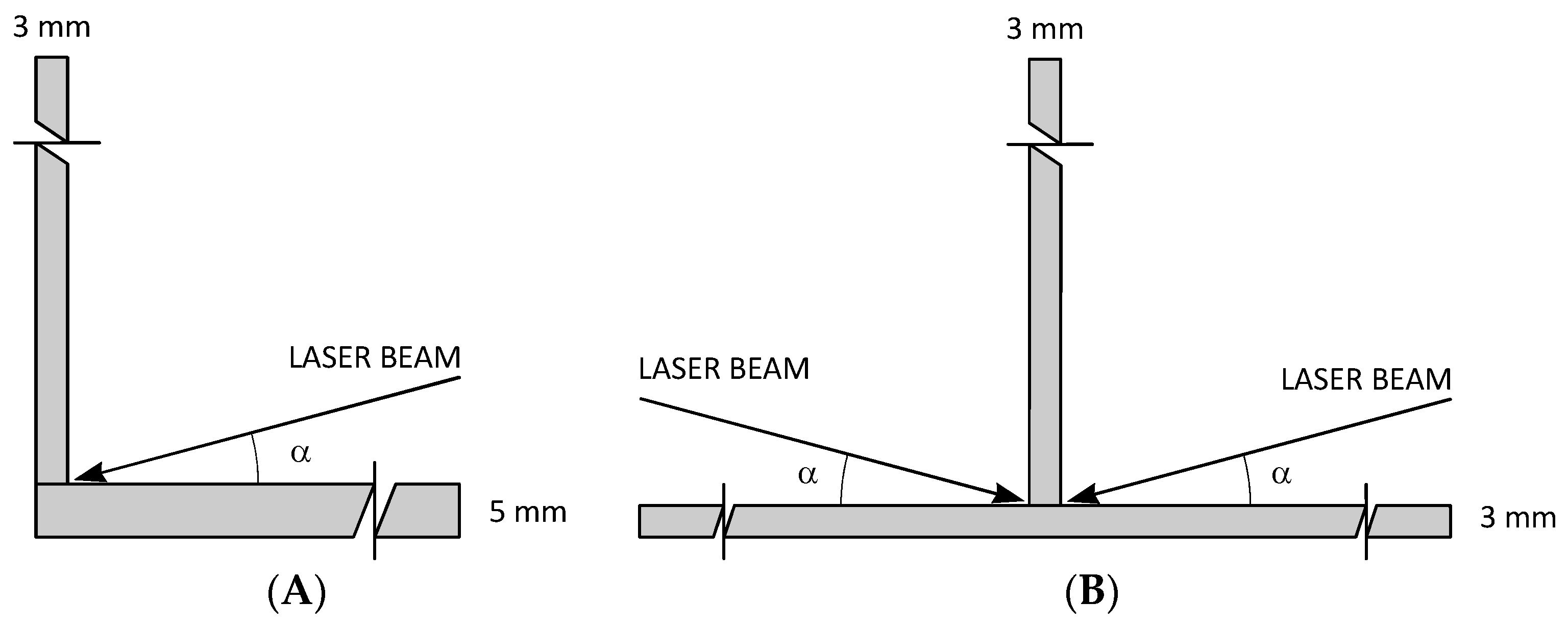
Figure 2.
T-joint, scheme for welding by means of two passes: (A) first pass, (B), second pass, each one being partially penetrative.
Figure 2.
T-joint, scheme for welding by means of two passes: (A) first pass, (B), second pass, each one being partially penetrative.
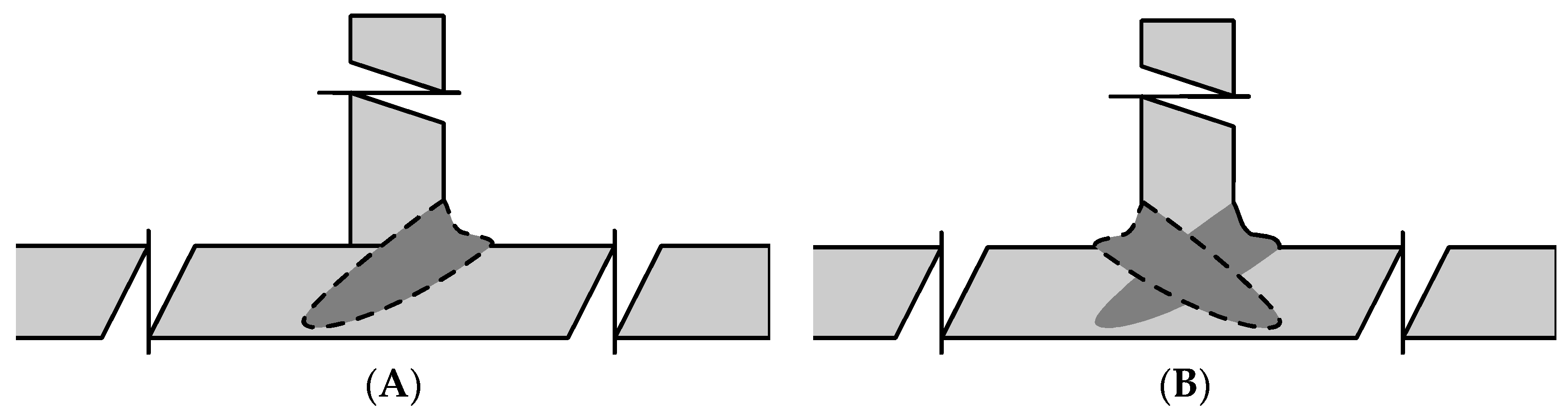
Figure 3.
The test-article for the assessment of laser beam welding (LBW) on titanium alloy.

Figure 4.
Components of the test-article: (A) cap-plate, (B) web-plate and (C) supporting rib; not to scale.
Figure 4.
Components of the test-article: (A) cap-plate, (B) web-plate and (C) supporting rib; not to scale.
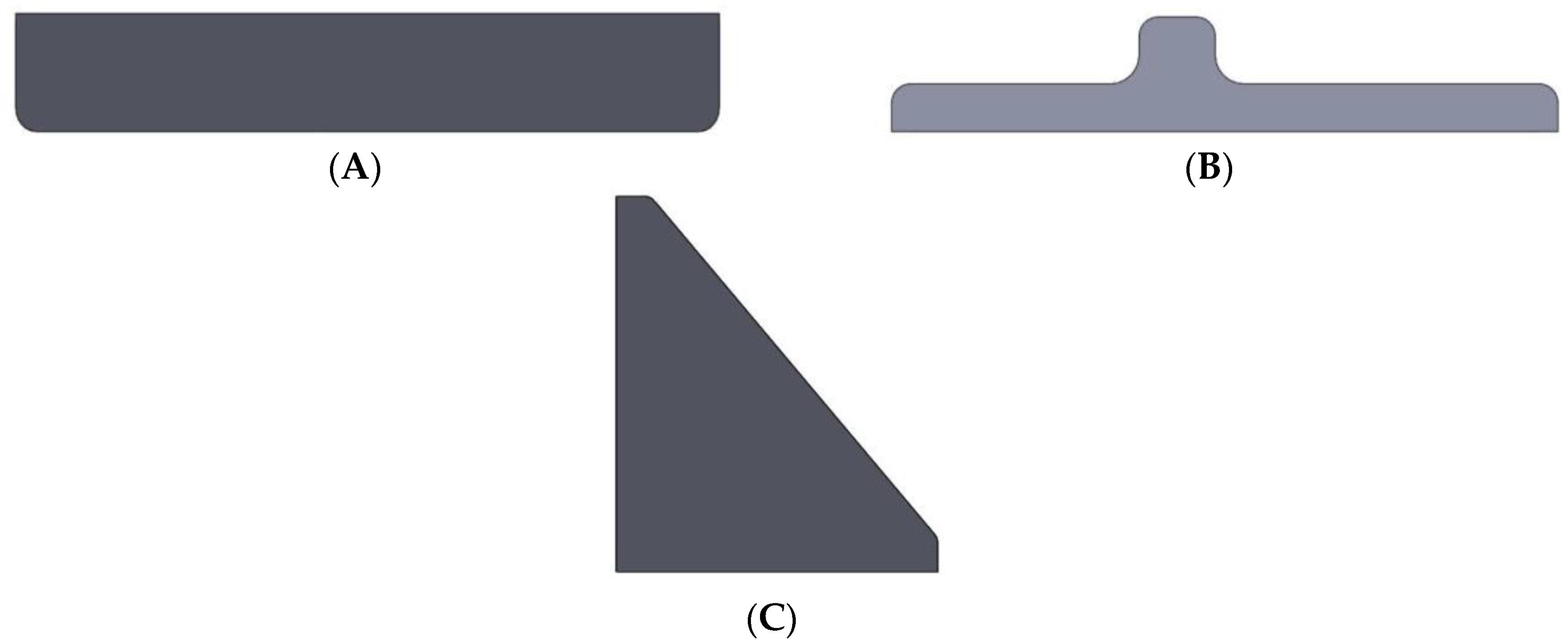
Figure 5.
Adjustable plain clamping of cap- and web-plates.
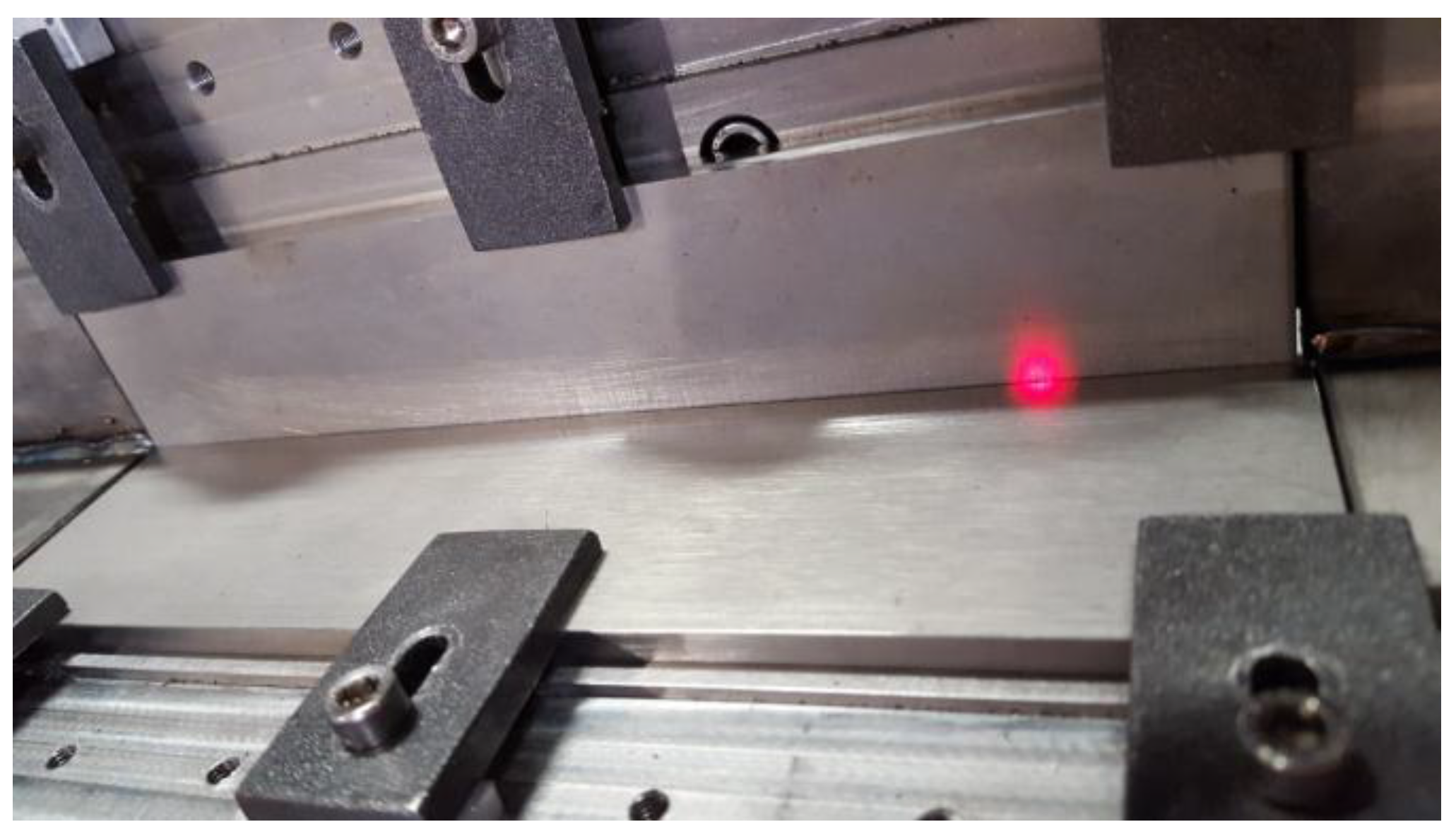
Figure 6.
Beam offset towards the web-plate with respect to the theoretical welding line.
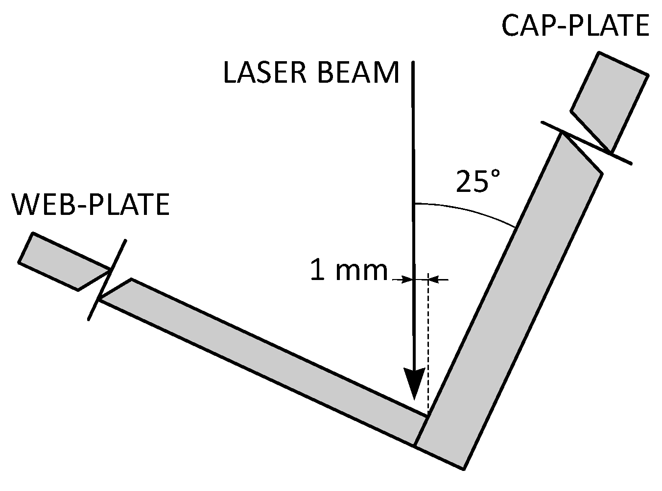
Figure 7.
Positioning of the nozzle for plasma blow and the diffuser for inert shielding supply; back-side view in the inset.
Figure 7.
Positioning of the nozzle for plasma blow and the diffuser for inert shielding supply; back-side view in the inset.

Figure 8.
Detail of the device for housing, positioning and concurrent shielding of the rib.

Figure 9.
Test-articles as resulting from LBW: (A) inner view; (B) outer view.
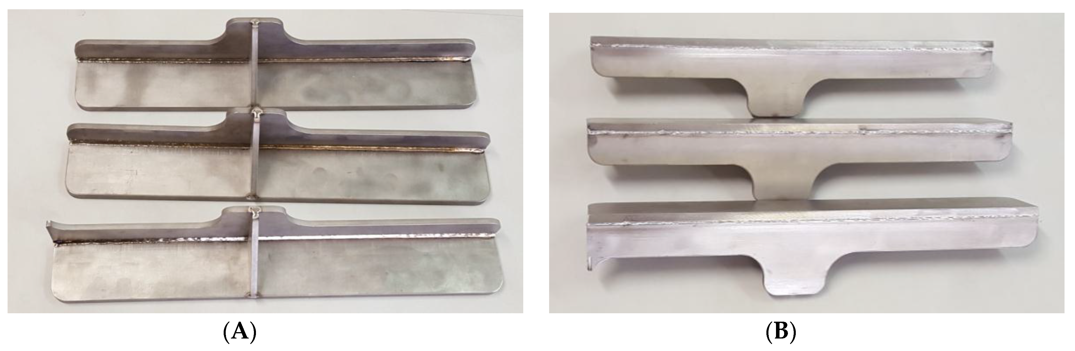
Figure 10.
Welding beads in the cross-sections, L-joints, welding speed of (A) 2400 mm∙min−1, (B) 3000 mm∙min−1, (C) 3600 mm∙min−1.
Figure 10.
Welding beads in the cross-sections, L-joints, welding speed of (A) 2400 mm∙min−1, (B) 3000 mm∙min−1, (C) 3600 mm∙min−1.
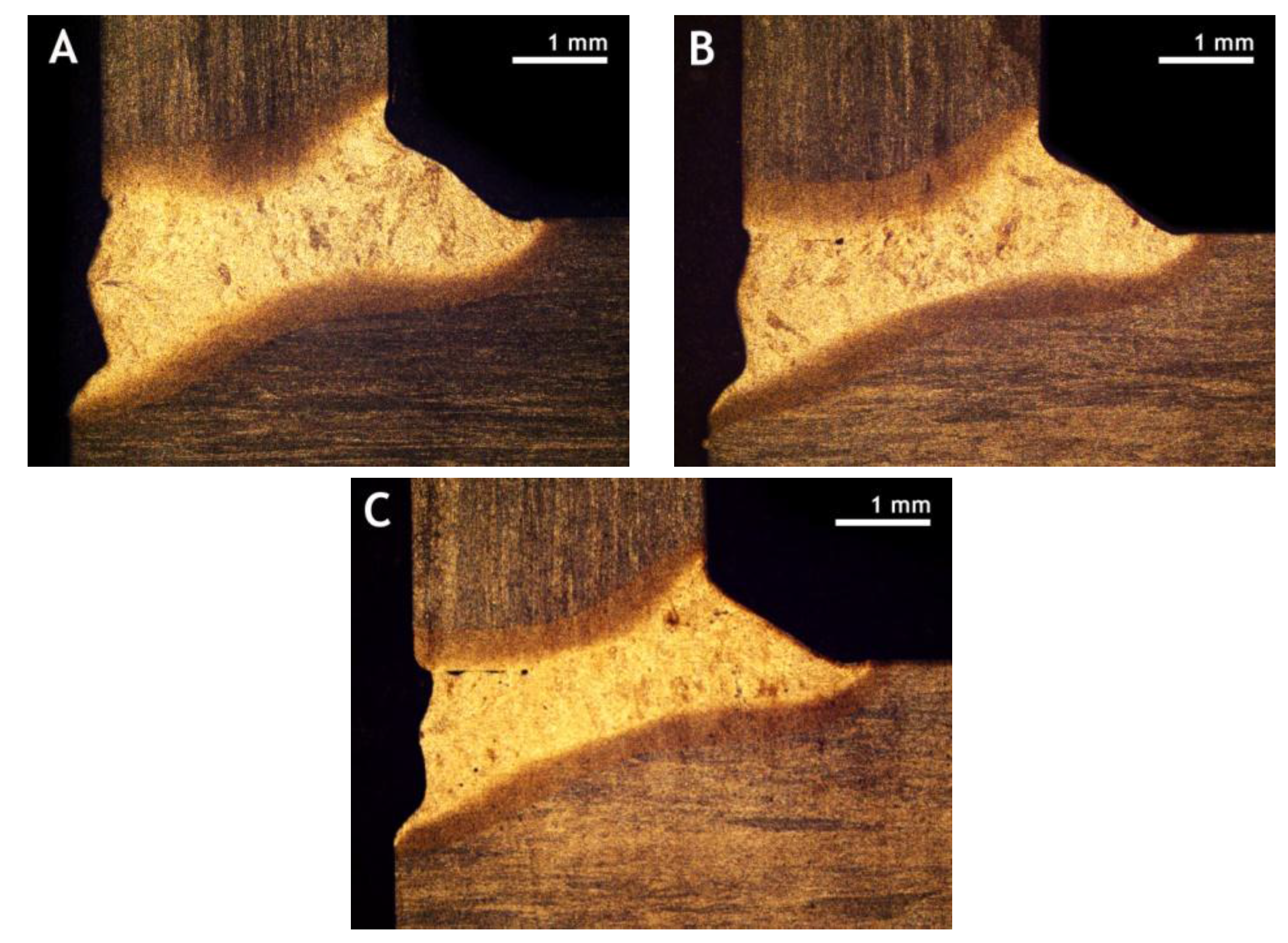
Figure 11.
Welding beads in the cross-sections, T-joints, approaching angle of (A) 20°, (B) 25°, (C) 30°.
Figure 11.
Welding beads in the cross-sections, T-joints, approaching angle of (A) 20°, (B) 25°, (C) 30°.

Figure 12.
L-joint, 2400 mm∙min−1: (A) martensitic α’ in the fusion zone; (B) microstructure of the heat-affected zone at the interface between fusion zone and unaffected parent metal.
Figure 12.
L-joint, 2400 mm∙min−1: (A) martensitic α’ in the fusion zone; (B) microstructure of the heat-affected zone at the interface between fusion zone and unaffected parent metal.

Figure 13.
Vickers microhardness trend at half-thickness of the 3 mm plate; L-joint, 2400 mm∙min−1.

Figure 14.
Ultrasonic non-destructive testing, indications due to micro-pores in scanning the T-joint.
Figure 14.
Ultrasonic non-destructive testing, indications due to micro-pores in scanning the T-joint.
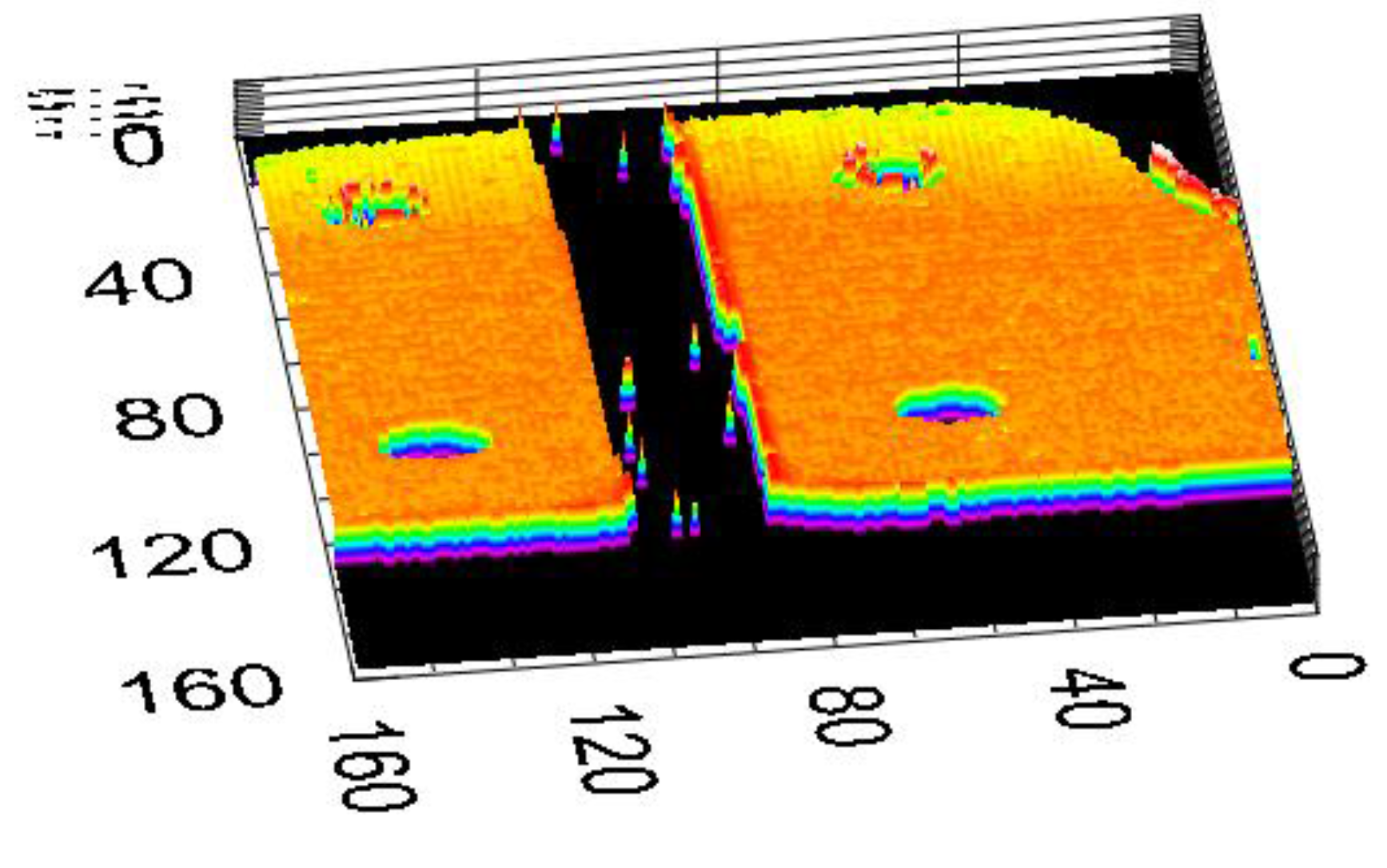
Figure 15.
Testing device for the test-article: (A) scheme, (B) real view.
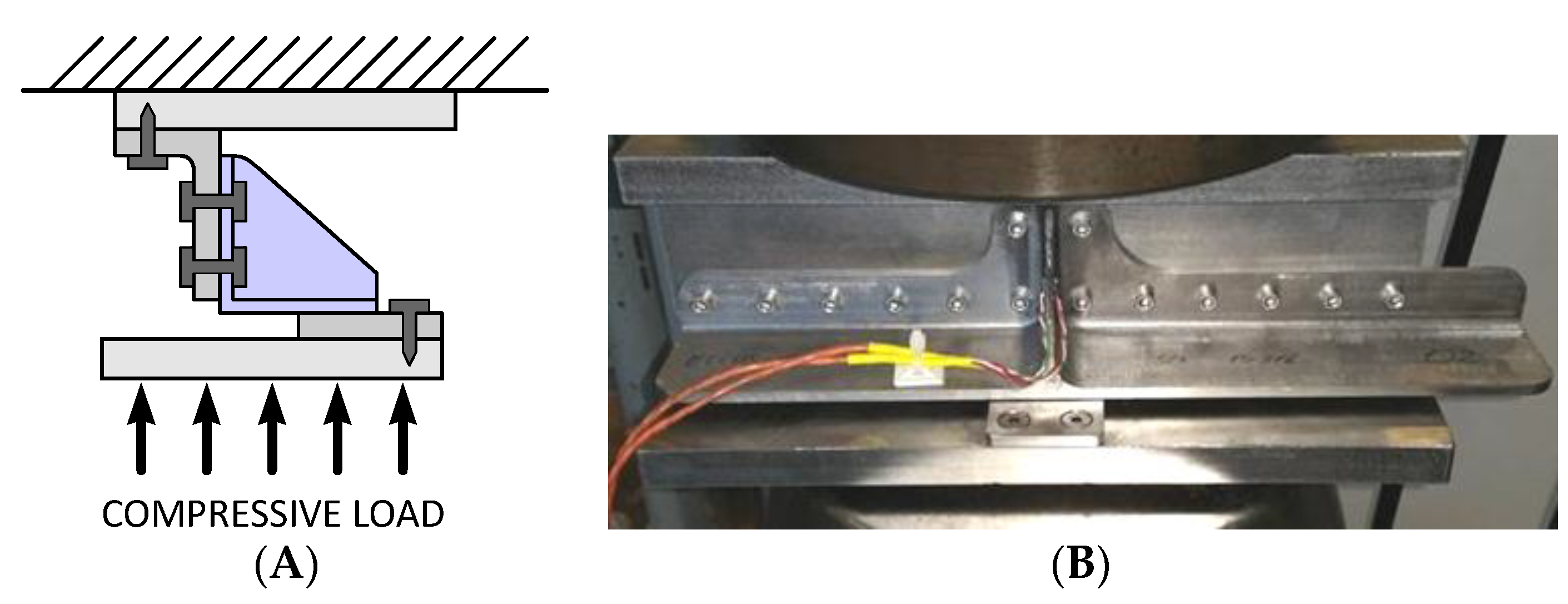
Figure 16.
Positioning of the strain gauges on the supporting rib for static testing.
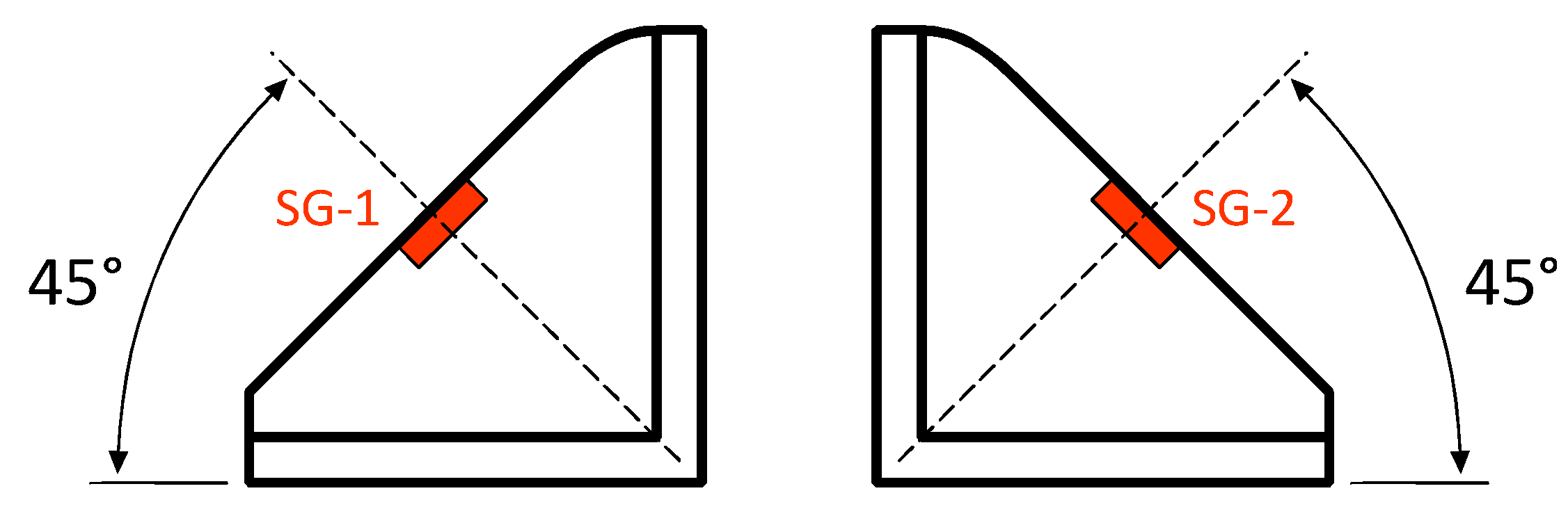
Figure 17.
Load-strain diagram, a comparison among machined and welded test-articles.


Table 1.
Processing conditions for sampling, based on the type of joint; focused beam.
| Joint Type | Power (kW) | Speed (mm∙min−1) | Approaching Angle (°) |
|---|---|---|---|
| L-joint | 6.0 | 2400 | 25 |
| 3000 | |||
| 3600 | |||
| T-joint | 6.0 | 4800 | 20 |
| 25 | |||
| 30 |
Table 2.
Laser welding system, main technical data.
| Parameter | Value |
|---|---|
| Maximum output power (kW) | 10.0 |
| Laser light wavelength (nm) | 1030 |
| Beam parameter product (mm × mrad) | 6.0 |
| Delivering fibre core diameter (μm) | 200 |
| Focus diameter (μm) | 300 |
Table 3.
Processing conditions for laser beam welding (LBW) of the test-article, based on the type of joint; focused beam.
Table 3.
Processing conditions for laser beam welding (LBW) of the test-article, based on the type of joint; focused beam.
| Joint Type | Power (kW) | Speed (mm∙min−1) | Approaching Angle (°) |
|---|---|---|---|
| L-joint (5 mm web-plate to 8 mm cap-plate) | 6.0 | 1650 | 25 |
| T-joint (5 mm rib to 8 mm cap; 5 mm to 5 mm web-plate) | 4.5 | 1650 | 20 |
Table 4.
Average strain as monitored by SG–1 and SG–2 as a function of load for welded and machined test-articles.
Table 4.
Average strain as monitored by SG–1 and SG–2 as a function of load for welded and machined test-articles.
| Testing Condition | Welded Test-Articles | Machined Test-Articles | ||
|---|---|---|---|---|
| Compressive load (kN) | Strain (SG–1) (10−3 mm/mm) | Strain (SG–2) (10−3 mm/mm) | Strain (SG–1) (10−3 mm/mm) | Strain (SG–2) (10−3 mm/mm) |
| 10 | 1.17 | 1.11 | 1.32 | 1.19 |
| 15 | 1.79 | 1.71 | 1.97 | 1.83 |
| 20 | 2.43 | 2.32 | 2.59 | 2.45 |
Table 5.
Theoretical and actual buy-to-fly ratio as resulting for each processing method.
| Technology | Theoretical Buy-to-Fly | Actual Buy-to-Fly |
|---|---|---|
| Machining from bulk | 11.0 | 15.1 |
| LBW and machining | 2.5 | 3.4 |
| LBW | 1.5 | 2.1 |
© 2017 by the authors. Licensee MDPI, Basel, Switzerland. This article is an open access article distributed under the terms and conditions of the Creative Commons Attribution (CC BY) license (http://creativecommons.org/licenses/by/4.0/).
Share and Cite
MDPI and ACS Style
Caiazzo, F.; Alfieri, V.; Corrado, G.; Argenio, P.; Barbieri, G.; Acerra, F.; Innaro, V. Laser Beam Welding of a Ti–6Al–4V Support Flange for Buy-to-Fly Reduction. Metals 2017, 7, 183. https://doi.org/10.3390/met7050183
AMA Style
Caiazzo F, Alfieri V, Corrado G, Argenio P, Barbieri G, Acerra F, Innaro V. Laser Beam Welding of a Ti–6Al–4V Support Flange for Buy-to-Fly Reduction. Metals. 2017; 7(5):183. https://doi.org/10.3390/met7050183
Chicago/Turabian StyleCaiazzo, Fabrizia, Vittorio Alfieri, Gaetano Corrado, Paolo Argenio, Giuseppe Barbieri, Francesco Acerra, and Vincenzo Innaro. 2017. "Laser Beam Welding of a Ti–6Al–4V Support Flange for Buy-to-Fly Reduction" Metals 7, no. 5: 183. https://doi.org/10.3390/met7050183
Note that from the first issue of 2016, this journal uses article numbers instead of page numbers. See further details here.