
Studying Mechanical Properties and Micro Deformation of Ultrafine-Grained Structures in Austenitic Stainless Steel


1
Institute of Engineering Technology, University of Science and Technology Beijing, Beijing 100083, China
2
Collaborative Innovation Center of Steel Technology, University of Science and Technology Beijing, Beijing 100083, China
*
Author to whom correspondence should be addressed.
Metals 2017, 7(6), 188; https://doi.org/10.3390/met7060188
Submission received: 17 April 2017
/
Revised: 14 May 2017
/
Accepted: 19 May 2017
/
Published: 24 May 2017
(This article belongs to the Special Issue Alloy Steels)
Abstract
:Eighty percent heavy cold thickness reduction and reversion transformation in the temperature range 700–950 °C for 60 s were performed to obtain the reverted ultrafine-grained (UFG) structure in 304 austenitic stainless steel. Through mechanical property experiments and transmission electron microscopy (TEM) of micro deformation of the UFG austenite structure, the tensile fractographs showed that for specimens annealed at 700–950 °C, the most frequent dimple sizes were approximately 0.1–0.3 μm and 1–1.5 μm. With the increase in annealing temperature, the dimple size distribution of nano-sized grains turned to micron-size. TEM micro deformation experiments showed that specimens annealed at 700 °C tended to crack quickly. In the grain annealed at 870 °C, partial dislocations were irregularly separated in the crystal or piled up normal to the grain boundaries; stacking faults were blocked by grain boundaries of small grains; twins held back the glide of the dislocations. In the grain annealed at 950 °C, the deformation twins were perpendicular to ε martensite. Fine grain was considered a strengthening phase in the UFG structure and difficult to break.
1. Introduction
Austenitic stainless steel (ASS) with its enhanced yield strength, high work hardening property, excellent weldability, and improved corrosion resistance has been put to use in many fields such as engineering applications and in everyday utensils [1,2,3]. Recently, the combination of high strength and high ductility in ultrafine-grained (UFG) structured ASS were achieved via operating severe deformation and reversion annealing treatment [4,5]. There are numerous recent papers discussing the deformation mechanisms in UFG steels from the microscopic or macroscopic view using conventional tensile testing and nanoindentation with TEM examination [4,5,6]. It is thought that deformation mechanisms in nanostructured metals can be different from those in coarse grained structures. It is suggested that partial dislocation generated at grain boundaries may be the main activity in UFG materials [7,8]. Allain et al. [9] has reported that the mechanical ε martensitic transformation only occurs if the stacking fault energy (SFE) is lower than 18 mJ/m2, that mechanical twinning occurs at SFE roughly in the range 12–35 mJ/m2 [10], and glide of dislocation would occur when SFE exceeds 45 mJ/m2. For 304 austenitic stainless steel under uniaxial tension, two transformation mechanisms were proposed according to the SFE [11,12,13,14]: (a) stress-induced-transformation γ → ε → α′ (<18 mJ/m2) and (b) strain-induced-transformation, γ → deformation twinning → α′ (12–35 mJ/m2). For materials with low SFE, the plastic deformation mode may change from dislocation slip to deformation twinning, which is important for material strengthening. It is reported that ASS commonly exhibits ductile failure controlled by dislocation flow or their mutual interactions. Meanwhile, the mechanism of ductile failure is well developed. Three parts of the mechanism are void nucleation, growth, and coalescence to form a crack, ending with fracture [15,16]. The ductile fracture of material consists of void nucleation and growth, which are governed by the motion of dislocations. It was realized that further information on the behavior of dislocations in the material might be obtained from a study of their motion. It has been possible to study the motion of dislocations in 304 ASS [14,17,18]. In the present investigation, a careful analysis of UFG of the fracture feature morphologies and the relation to the mechanical properties has been made in the ASS. TEM micro deformation tensile test of ASS with UFG structure deformation experiments were conducted to discuss the state of deformation mechanisms and fracture mechanisms.
2. Material and Experimental Methods
The 304 ASS used in this study had chemical composition (weight percent) Fe–0.04C–0.16Si–1.52Mn–17.8Cr–8.1Ni–0.005P–0.005S. Several specimens with of dimension 7.9 mm × 80 mm × 600 mm were machined for subsequent solution treatment and thermomechanical processes. The plates were solution-treated at 1050 °C for 12 min. The solution-treated specimens were cold rolled to 80% reduction in thickness and were subjected to reversion transformation at temperatures of 700–950 °C for 60 s to obtain a reverted UFG austenite structure.
Phase characterization was conducted during cold rolling and annealing by electron backscatter diffraction (EBSD, ZEISS ULTRA 55, Carl Zeiss, Germany) and X-ray diffractometry (Rigaku DMAX-RB with Cu-Kα radiation, Rigaku, Tokyo, Japan) (XRD). Before EBSD and XRD, the specimens were prepared by electropolishing at 15 V for 30 s to remove deformation-induced martensite on the surface; the electrolyte contained 20 vol % perchloric acid and 80 vol % ethanol.
Tensile tests were carried out at room temperature using the CMT5605 tensile machine (SANS Testing Machine Co., Ltd., Shenzhen, China) and Vickers micro-hardness values were measured on an HV-1000 micro-Vickers durometer (Shanghai optical instrument factory, Shanghai, China)to obtain the mechanical properties of the UFG structure. After sample fracture, scanning electron microscopy (SEM, FEI Quanta-450; FEI Corporation, Hillsboro, OR, USA) was used to obtain SEM fractographs. Image processing technique was employed on the digital fractographs to describe the two-dimensional dimple features on the fracture surfaces using Image-Pro Plus (Version 6.0, Media Cybernetics, Inc., Rockville, MD, USA, 2006).
Three tensile specimens for micro deformation TEM (transmission electron microscopy) observation were cut from the UFG austenite. Subsequently, the foils for the tensile observation by TEM were thinned until perforation by twin-jet electropolishing apparatus in a solution of 10 vol % of perchloric acid and 90 vol % of ethanol at a voltage of 36 V and a temperature of 0 °C. Tensile micro deformation was carried out in a JEM2100 TEM (JEOL Ltd., Tokyo, Japan). TEM was used to observe the inner feature of the UFG structure until cracks appeared in the thin area.
3. Results and Discussion
3.1. Microstructure Characterizations of the 304 ASS with UFG Structure
The SFE of the ASS is the key factor determining whether twinning, martensite transformation, or dislocation glide will dominate the deformation process. Schramm and Reed [19] proposed Equation (1) for calculating SFE. The SFE (in mJ/m2) of 304 ASS can be calculated by
where CNi, CCr, CMn and CMo are the content values (in wt %) of Ni, Cr, Mn, and Mo, respectively. From the chemical composition, SFE of the sample used in this study was evaluated to be ~14.5 mJ/m2.
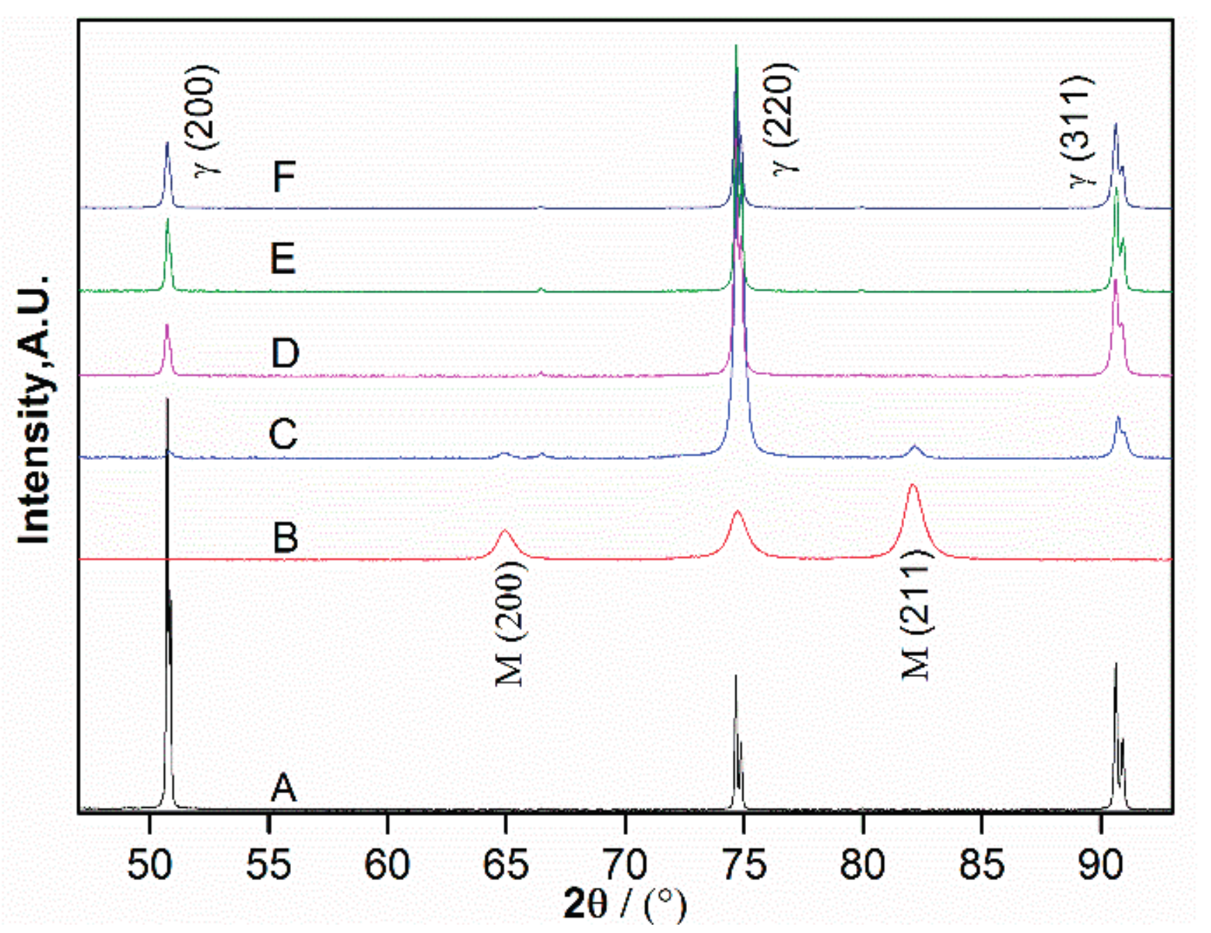
X-ray patterns of the experimental alloy in the solution-treated condition after 80% cold rolling and upon reversion annealing at various temperatures are depicted in Figure 1. The solution-treated specimen exhibited entirely austenite peaks. After 80% cold rolling, the microstructure of the 304 ASS changed to mainly martensite due to the heavy cold reduction, as shown by XRD pattern B in Figure 1. Upon reversion annealing, the martensite reverted to austenite. The intensity of the austenite peaks increased with increasing temperature in the range 700–950 °C, which indicates an increase in the volume fraction of austenite with respect to martensite. Upon annealing at 700 °C, the microstructure mostly consisted of austenite (accounting for 65%) along with a small amount of retained martensite (accounting for 35%). On the other hand, increasing the temperature to 820 °C resulted in reversion of almost all the martensite to austenite, whose volume fraction was 99.5% (calculated from Figure 1).
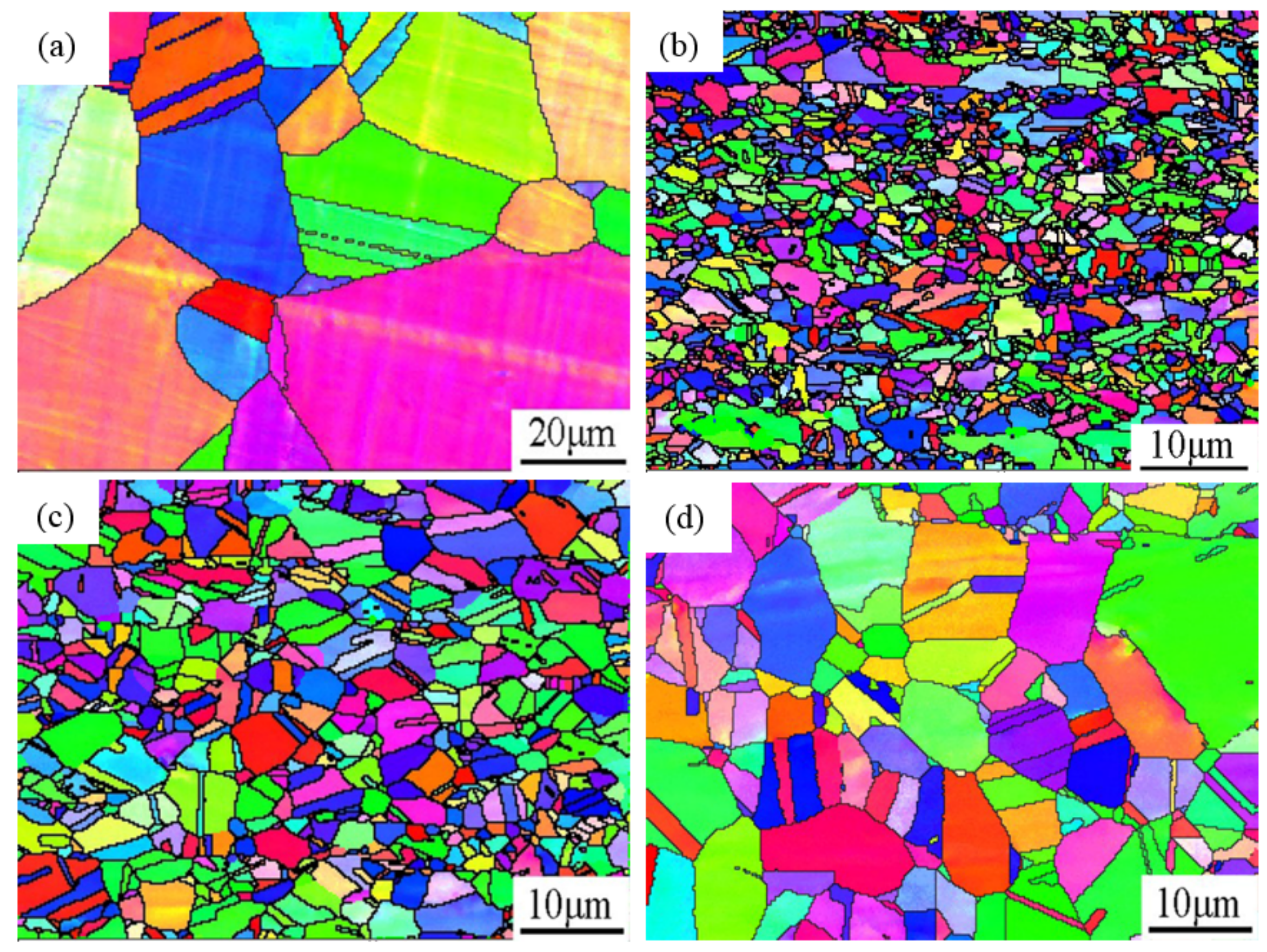
EBSD showed that for the specimen solution-treated at 1050 °C for 12 min, the grain size was approximately 20–40 μm, as shown in Figure 2a. For the specimens annealed at 820 °C (shown in Figure 2b), the average grain size was about 500 nm, while the specimens annealed at 870 °C (shown in Figure 2c) had average grain size of about 2 μm. With annealing temperature increasing to 950 °C (shown in Figure 2d), the average grain size was about 5 μm. However, the grain size of the sample annealed at 700 °C for 60 s was too small to be discerned by EBSD. Therefore, in this work, TEM observations were performed on the sample annealed at 700 °C for 60 s to measure the grain size, as shown in Figure 3. The statistical result indicates that the grain size was about 150 nm, with 35% martensite mixed with austenite.
3.2. Mechanical Experiments for the 304 ASS with UFG Structure
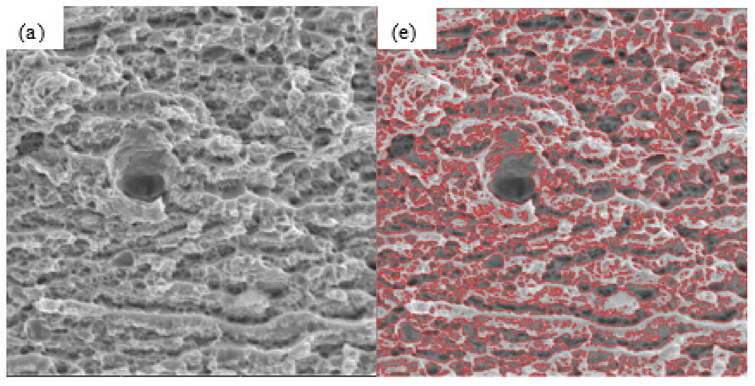
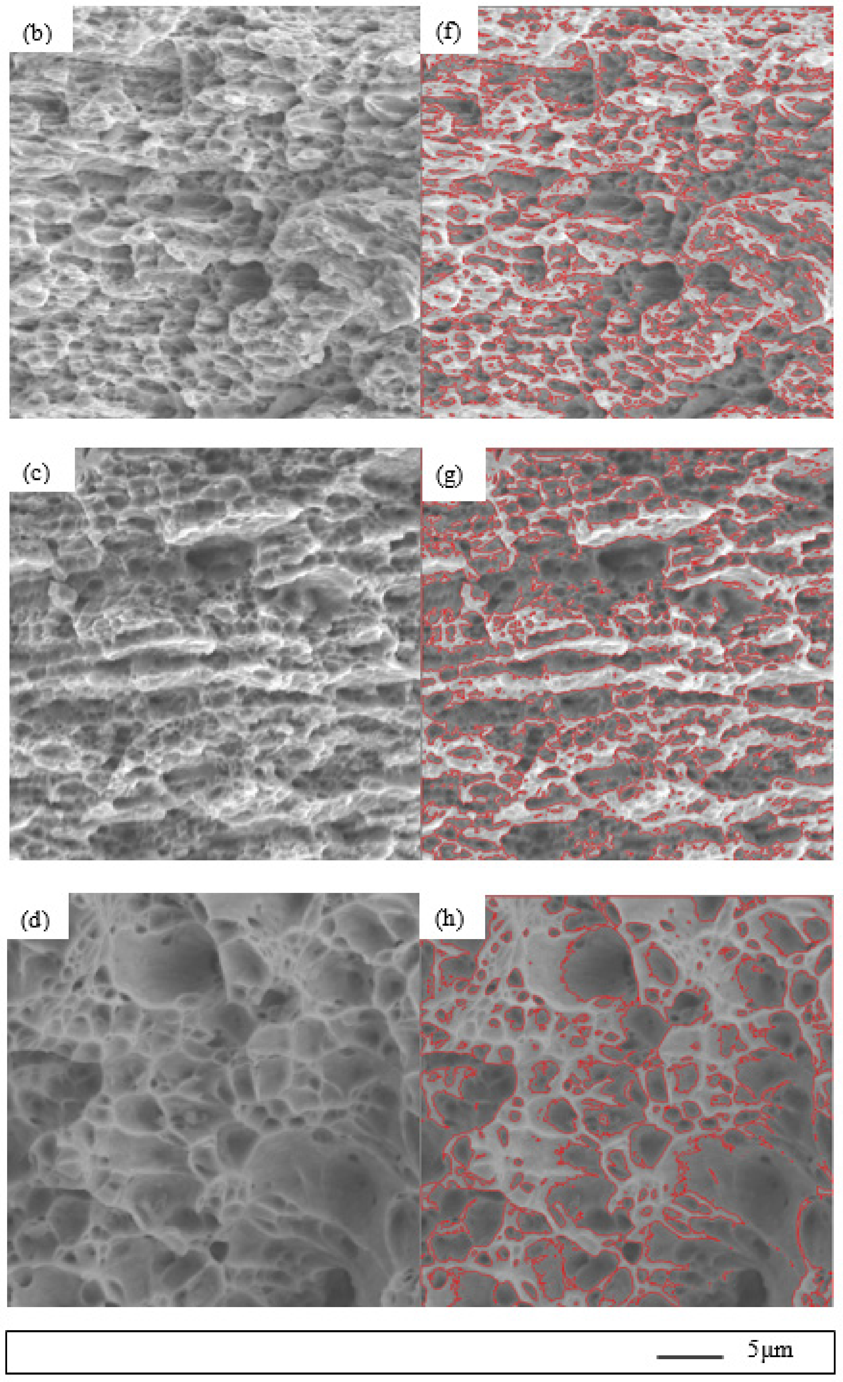
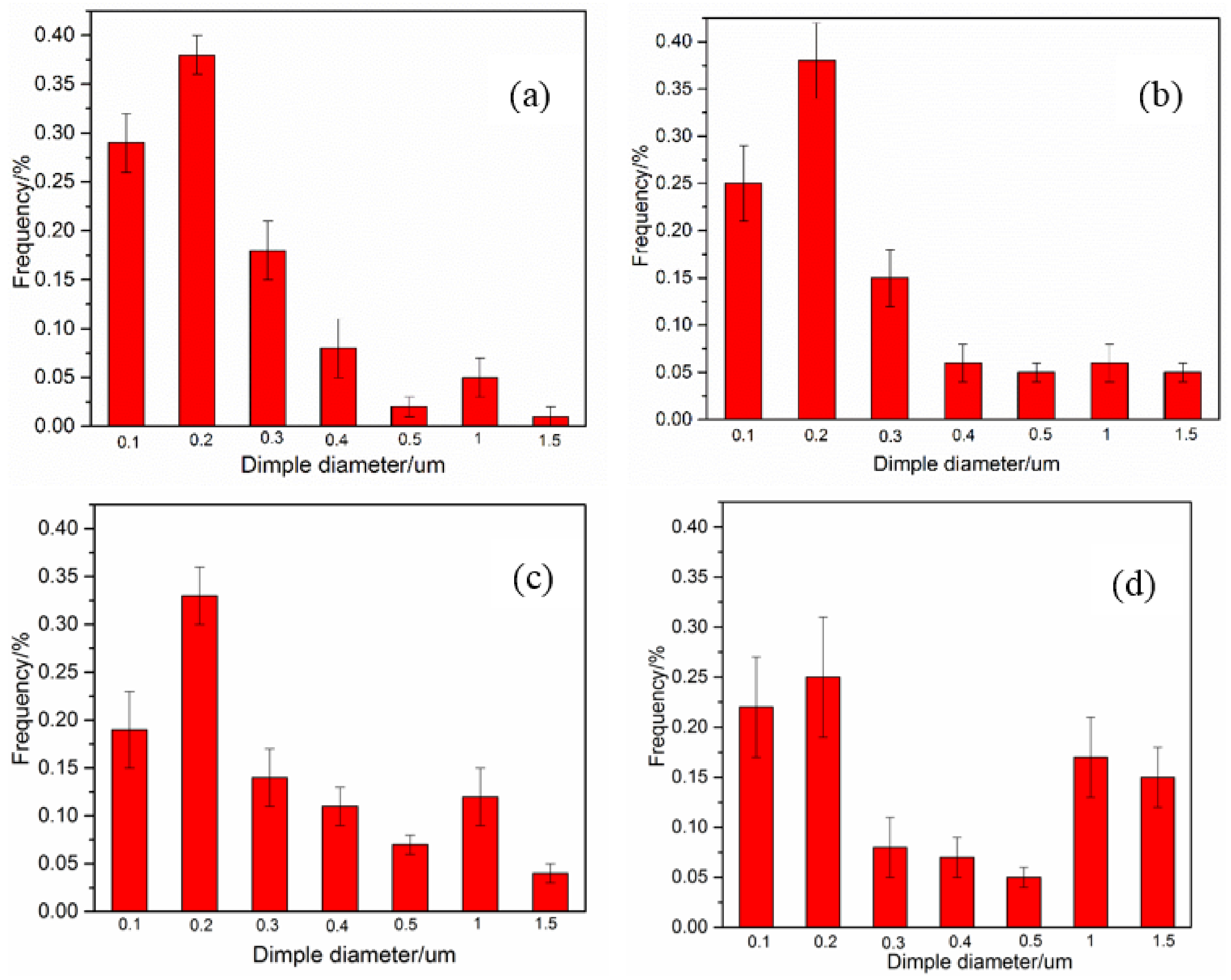
Tensile tests were carried out at room temperature. The tensile fractographs of four specimens are shown in Figure 4a–d. Image processing (IP) was used to characterize the two-dimensional geometry of dimples to obtain the dimple diameter and its distribution on the fracture surfaces, as shown in Figure 4e–h. Figure 5 shows the dimple size distribution after annealing at different temperatures. As shown in Figure 5, the most frequent dimple sizes were approximately 0.1–0.3 μm and 1–1.5 μm. With the increase of annealing temperature, the nano-sized dimple size distribution changed to micron-sized.
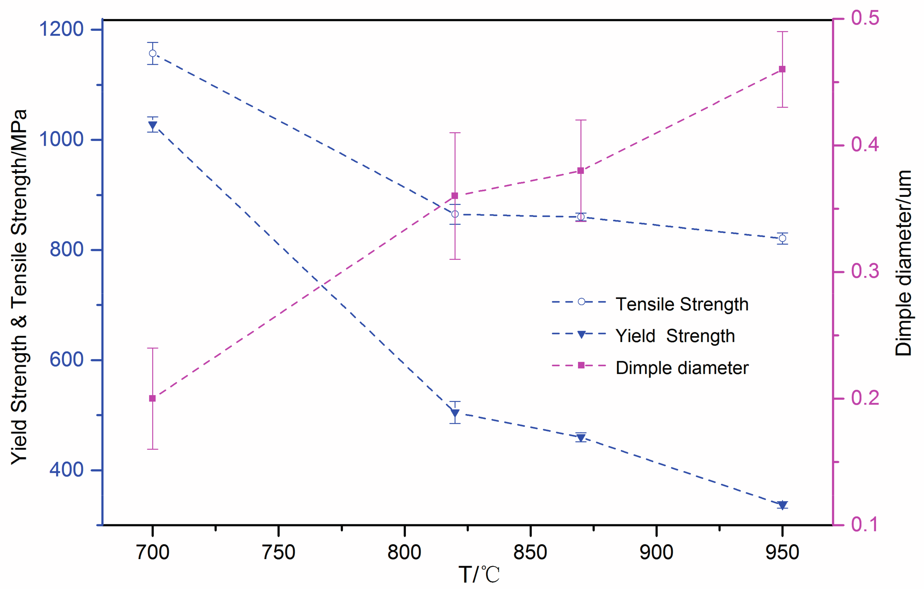
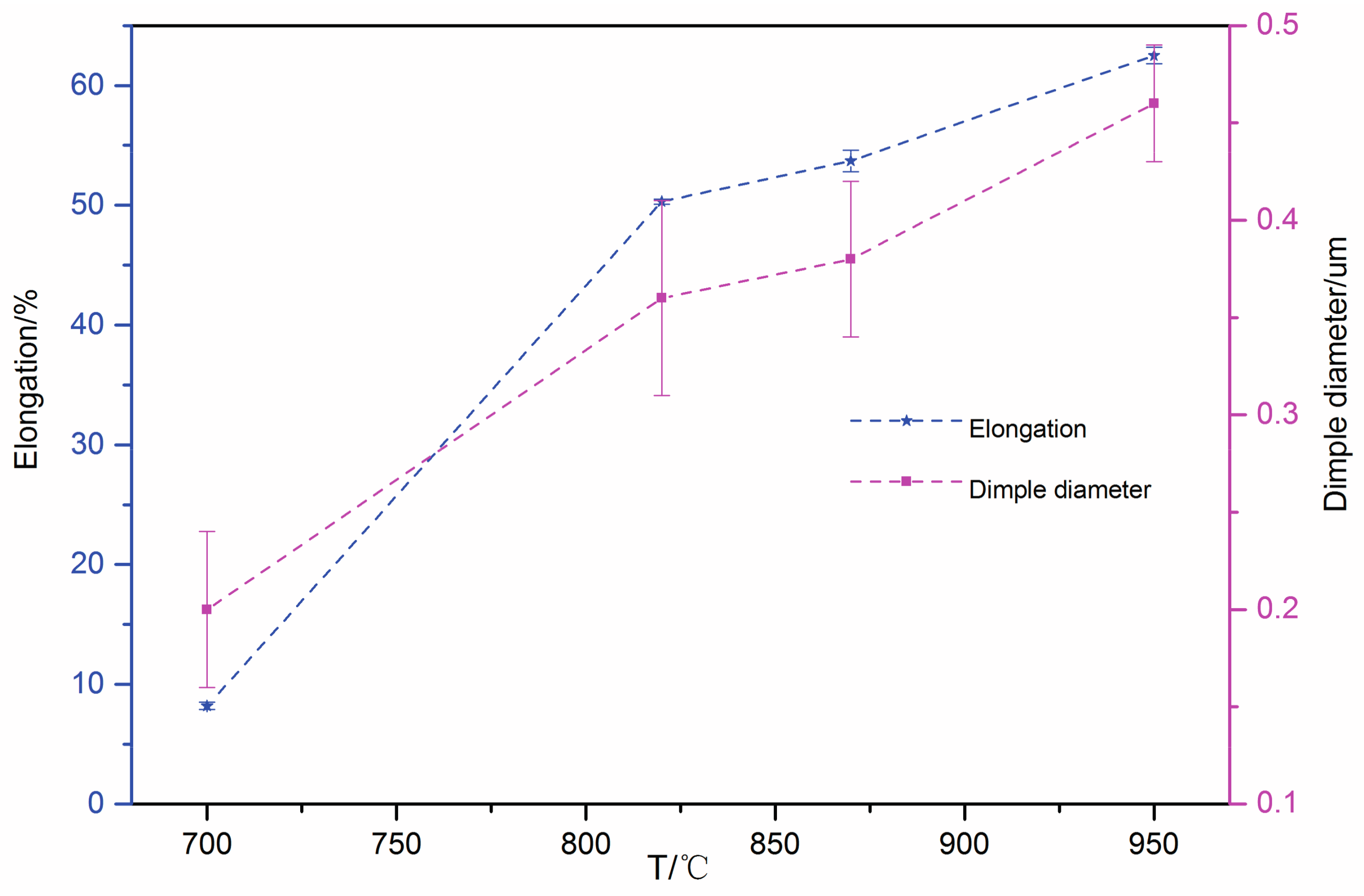
The curves of strength properties and ductility properties with average dimple diameter at different annealing temperatures are shown in Figure 6 and Figure 7, respectively. With increase in annealing temperature, the strengths decreased, while the elongation and the average size of the dimple increased. In comparison with the specimen annealed at 700 °C, the other three UFG specimens (annealed at 820, 870, and 950 °C) exhibited significantly higher ductility and lower strength. The yield strength of the specimen annealed at 700 °C was 1028 ± 14 MPa, which is approximately 3 times higher than that of the specimen annealed at 950 °C and the ultimate tensile strength was 1157 ± 20 MPa. Meanwhile, the gap between the yield strength and tensile strength increased with increasing annealing temperature. The elongation-to-failure were 8.2 ± 0.3%, 50.3 ± 0.2%, 53.7 ± 0.9%, and 62.5 ± 0.7% for the specimens annealed at 700, 820, 870 and 950 °C, respectively. Specimens with UFG structure annealed at 820, 870 and 950 °C led to higher uniform elongation during the tensile test.
3.3. Micro Deformation Experiments for the 304 ASS with UFG Structure
3.3.1. Deformation Mechanisms for Specimen Annealed at 700 °C
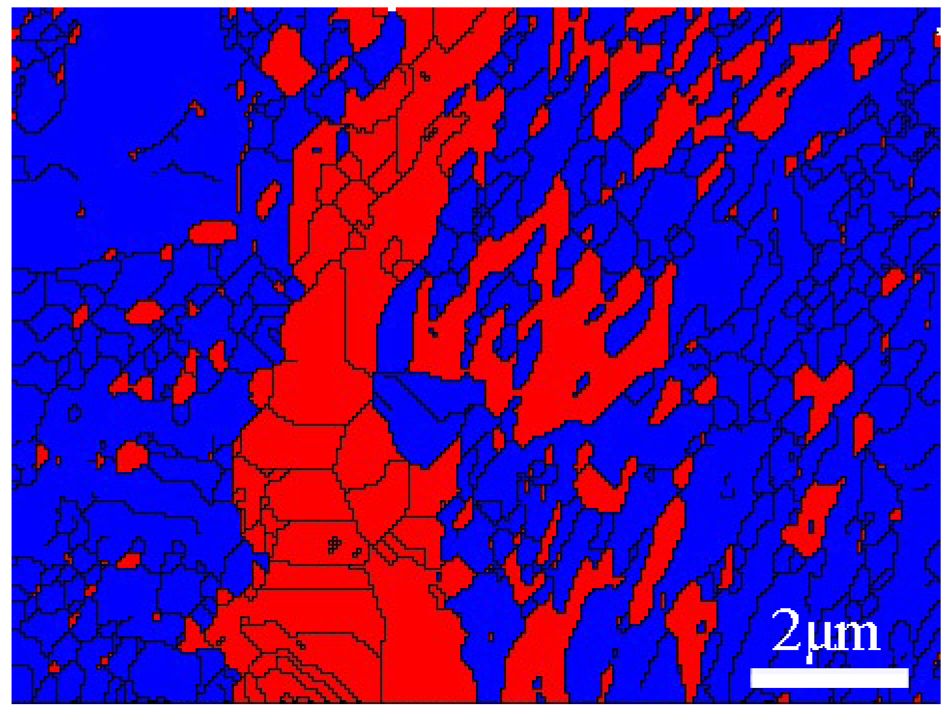
Three UFG foils for the micro deformation were studied out via TEM. The stress direction in the tensile test is shown in Figure 8, 10 and 13. It was found that the specimen annealed at 700 °C during the micro deformation experiment tended to crack quickly. This may be attributed to the combined effect of the low ductility of the UFG and the existence of martensite. From the micro deformation observation shown in Figure 8, it was found that some pile-ups of closely dense dislocations ended in cracks and the dislocation pile-ups disappeared after the crack. Further, the dislocation pile-ups only took place on either side of the crack. In other words, the stress concentrated on the tip of the crack with inc mentals-183011 reasing stress during the tensile test. No dislocation pile ups appeared in the other grains. Further straining could not produce additional interactions on the grains since cracks had generated elsewhere, which relieved the stress on the dislocation pile-ups. Figure 9 shows the phase map after micro deformation tensile test of the specimen annealed at 700 °C for 60 s, taken 5–10 μm away from the crack. The blue color represents the austenite phase and the red color represents the martensite phase. From the micro deformation of the foils, it was found that part of the strain induced martensite transformation from austenite.
3.3.2. Deformation Mechanisms for Specimen Annealed at 870 °C
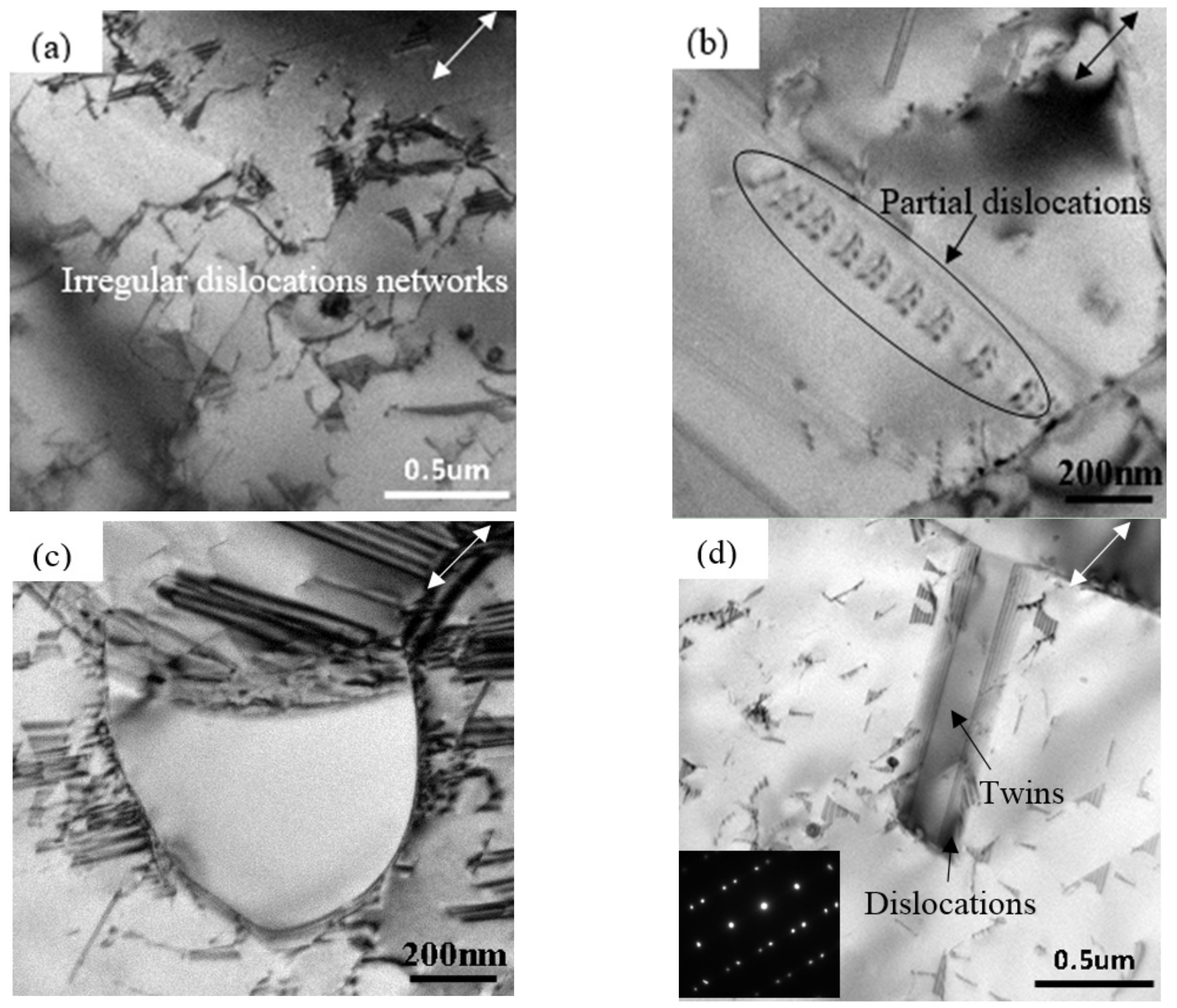
Because of the low SFE of the 304 ASS in this study, partial dislocations that act as glide dislocations were more widely separated than in high SFE materials, as shown in Figure 10a. A few isolated dislocations, pile-ups, or irregular networks appeared in some areas (see the label in Figure 10a). Most of the irregular objects appeared to be partial dislocations in the pile-ups. This means that it was easier to activate a partial dislocation than a full dislocation in the UFG microstructure with average grain size 2 μm. The space of the dislocations in the pile-ups did not vary regularly in the manner expected from the calculations of Eshelby et al. [20], but were much more irregular. Figure 10b marks a set of partial dislocations arranged in a row and breaking up to some distance. The picture shows that the piled-up structure (arranged at grain boundaries) that was used to illuminate the relation between flow stress and grain size is largely correct [21]. It was confirmed that these dislocations are parallel to (111)γ slip planes, hence the planes that contain these dislocations must be (111)γ slip planes for all orientations observed [22]. In some areas, multiple striped bands appeared, as shown in Figure 10c. For the steel with average grain size of 2 μm, it was found that numerous dislocations were blocked by grain boundaries of small grains. It was thought that these bands are due to stacking faults produced by the movement of partial dislocations. In contrast to the motion of dislocations in aluminum, cross slipping has not been observed within the individual grains [12]. This can be attributed to the large width of stacking faults, speculated from the low SFE and the subsequent difficulty of developing constrictions. In addition, as shown in Figure 10d, twins with high-angle boundary (see black arrow in Figure 10d) retarded the glide of the dislocations could therefore enhance the strain-hardening rate, as shown in Figure 11 [6]. These structures are typical in low SFE materials. According to the reference [23], it is indicated that the transformation mechanism was via γ → deformation twinning → α′.
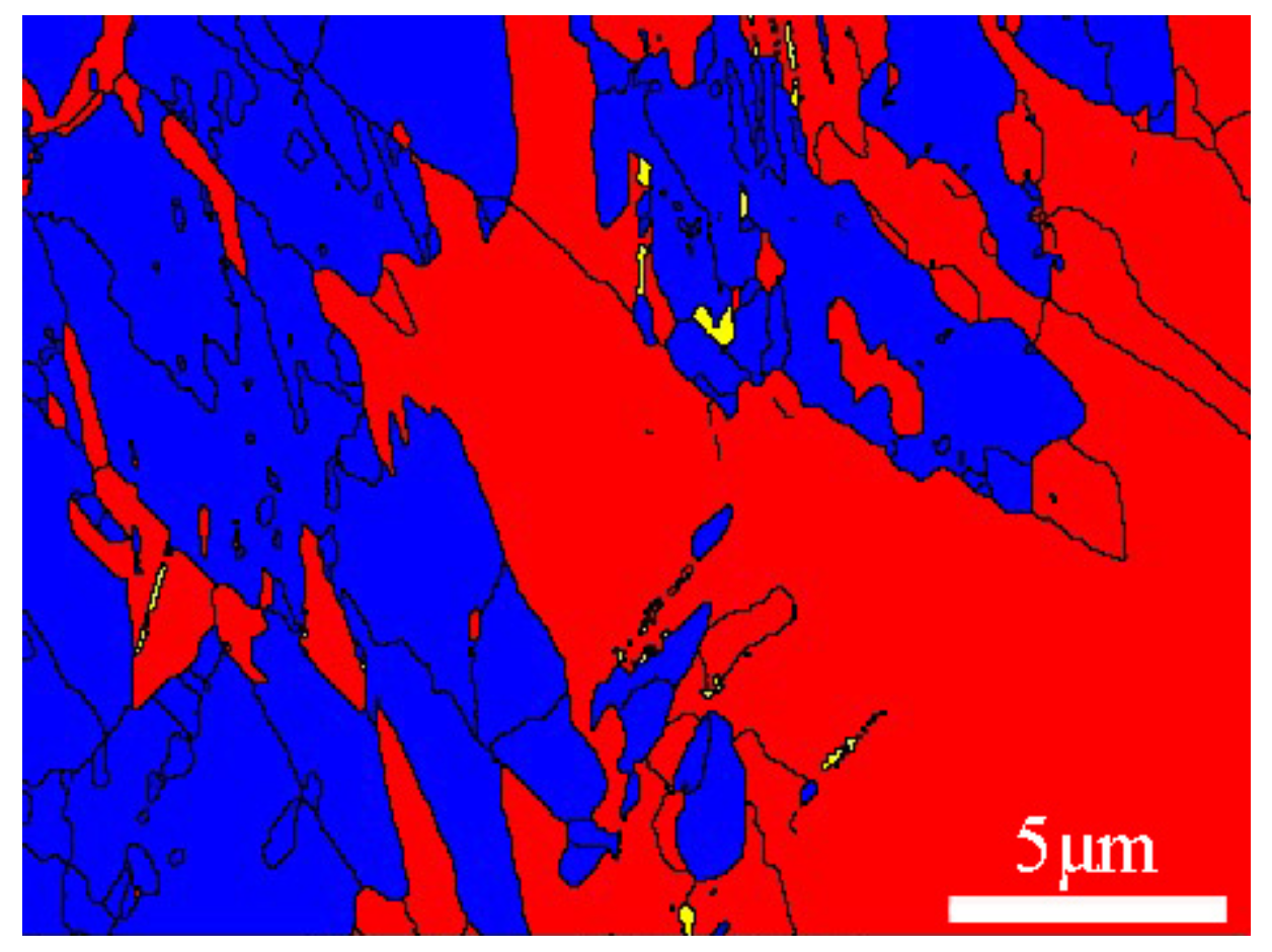
A phase map of the specimen annealed at 870 °C for 60 s after the micro deformation tensile test, 5–10 μm away from the crack is shown in Figure 12. The blue color represents the austenite phase, the red color represents the martensite phase, and the yellow color represents the ε martensite phase. It can be observed that ε martensite was included in α′ martensite, which indicated that the transformation mechanism was γ → ε → α′. As mentioned above, a conclusion can be reached that α′ martensite might nucleate by deformation twins, ε martensite, or their intersections [23].
3.3.3. Deformation Mechanism for Specimen Annealed at 950 °C
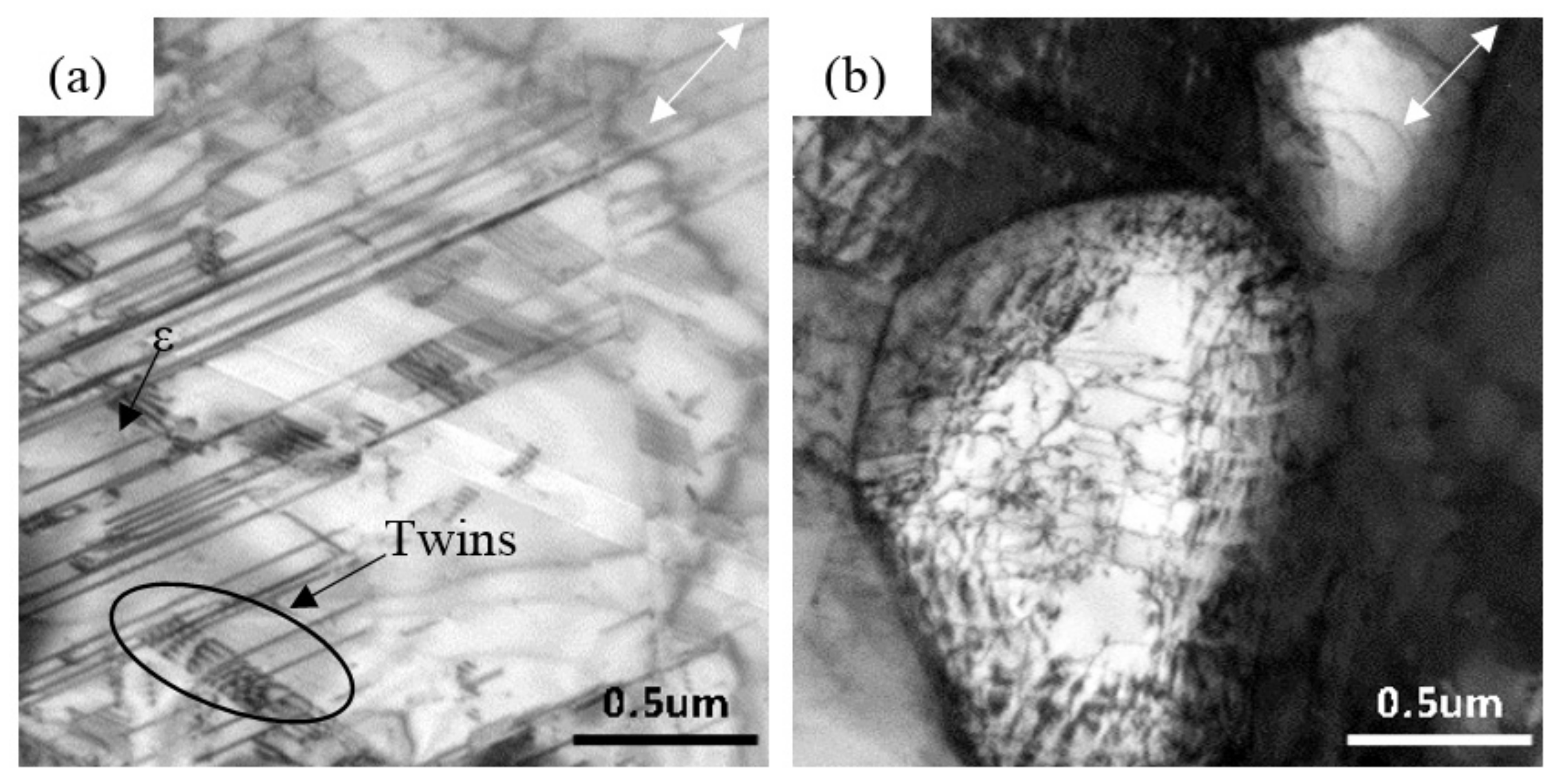
ε martensite was found as marked in Figure 13a. Meanwhile, the deformation twins clearly appeared in the deformed austenite microstructure (circled in Figure 13a). In addition, the directions of all deformation twins were nearly perpendicular to that of ε martensite, which is consistent with the results of Li et al. [14], who reported that deformation twins grow along the direction perpendicular to ε martensite with increasing deformation. In fcc metals, stacking faults and deformation twins can be dissociated from a screw dislocation or a 60° dislocation [13]. Stacking faults overlapped within the (111)γ plane of the fcc crystal, which promoted the generation of deformation twins [24]. As the (111)γ plane slipped due to the increase of deformation, the ()ε planes were perpendicular to the (111)γ planes [25]. Hence, the observation on deformation twins in the direction vertical to ε martensite is correct. According to calculation of the SFE of 304 ASS, the energy is in the range 12–35 mJ/m2.
Dense dislocation arrangements accumulated inside grains of size 2 μm, while thin dislocation was observed inside grains of size 500 nm, as shown in Figure 13b. Apparently, this differs from the specimen annealed at 870 °C in terms of the transformation of UFG during the tensile test. It is indicated that the coarse grain generates dislocation pile-ups more easily than the fine grain, which is considered a strengthening phase in the UFG structure and difficult to break.
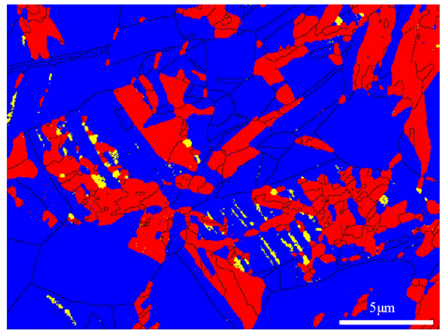
Phase map of the specimen annealed at 950 °C for 60 s after the micro deformation tensile test, 10–15 μm away from the crack is shown in Figure 14. The blue color represents the austenite phase, the red color represents the martensite phase, and the yellow color represents the ε martensite phase. The ε martensite appeared as a band included in α′ martensite, which indicated that the transformation mechanism was γ → ε → α′, namely the stress-induced-transformation.
4. Conclusions
The tensile fractographs of the obtained UFG structure show that the most frequent dimple sizes were approximately 0.1–0.3 μm and 1–1.5 μm. With increasing annealing temperature, nano-sized grains grew to micron-sized grains and the strengths decreased, while the elongation and average size of the dimples increased.
For the 304 ASS with different grain sizes during the micro deformation experiment, (a) the specimen annealed at 700 °C tended to crack quickly.This may be attributed to the combined effect of the low ductility of the UFG and the existence of martensite. (b) In the sample annealed at 870 °C with average grain size 2 μm, partial dislocations were widely separated in the irregular crystals or piled up normal to the grain boundaries; stacking faults were blocked by grain boundaries of small grains; twins prevented gliding of the dislocations. It can be concluded that α′ martensite might nucleate through deformation twins, ε martensite or their intersections. (c) The deformation twins of the sample annealed at 950 °C with average grain size 5 μm were perpendicular to the ε martensite. Fine grain was considered as the strengthening phase in the UFG structure and was difficult to break.
Acknowledgments
This work was financially supported by the National Natural Science Foundation of China (Grant No. 51474031).
Author Contributions
Na Gong and Hui-Bin Wu conceived and designed the experiments; Na Gong and Zhi-Chen Yu performed the experiments; Na Gong and Gang Niu analyzed the data; Na Gong and Zhi-Chen Yu were responsible for language modification; Da Zhang contributed reagents/materials/analysis tools; Na Gong wrote the paper.
Conflicts of Interest
The authors declare no conflict of interest.
References
- Huang, G.L.; Matlock, D.K.; Krauss, G. Martensite formation, strain rate sensitivity, and deformation behavior of type 304 stainless steel sheet. Metall. Trans. A 1989, 20, 1239–1246. [Google Scholar] [CrossRef]
- Hedayati, A.; Najafizadeh, A.; Kermanpur, A.; Forouzan, F. The effect of cold rolling regime on microstructure and mechanical properties of AISI 304L stainless steel. J. Mater. Process. Technol. 2010, 210, 1017–1022. [Google Scholar] [CrossRef]
- Choi, J.; Jin, W. Strain induced martensite formation and its effect on strain hardening behavior in the cold drawn 304 austenitic stainless steels. Scr. Mater. 1997, 36, 99–104. [Google Scholar] [CrossRef]
- Misra, R.D.K.; Kumar, B.R.; Somani, M.; Karjalainen, P. Deformation processes during tensile straining of ultrafine/nanograined structures formed by reversion in metastable austenitic steels. Scr. Mater. 2008, 59, 79–82. [Google Scholar] [CrossRef]
- Challa, V.S.A.; Wan, X.L.; Somani, M.C.; Karjalainen, L.P.; Misra, R.D.K. Significance of interplay between austenite stability and deformation mechanisms in governing three-stage work hardening behavior of phase-reversion induced nanograined/ultrafine-grained (NG/UFG) stainless steels with high strength-high ductility combination. Scr. Mater. 2014, 86, 60–63. [Google Scholar]
- Misra, R.D.K.; Zhang, Z.; Jia, Z.; Somani, M.C.; Karjalainen, L.P. Probing deformation processes in near-defect free volume in high strength–high ductility nanograined/ultrafine-grained (NG/UFG) metastable austenitic stainless steels. Scr. Mater. 2010, 63, 1057–1060. [Google Scholar] [CrossRef]
- Shen, F.; Zhou, J.; Liu, Y.; Zhu, R.; Zhang, S.; Wang, Y. Deformation twinning mechanism and its effects on the mechanical behaviors of ultrafine grained and nanocrystalline copper. Comp. Mater. Sci. 2010, 49, 226–235. [Google Scholar] [CrossRef]
- Capolungo, L.; Cherkaoui, M.; Qu, J. On the elastic-viscoplastic behavior of nanocrystalline materials. Int. J. Plast. 2007, 23, 561–591. [Google Scholar] [CrossRef]
- Allain, S.; Chateau, J.P.; Bouaziz, O. A physical model of the twinning-induced plasticity effect in a high manganese austenitic steel. Mater. Sci. Eng. A 2004, 387, 143–147. [Google Scholar] [CrossRef]
- Cohen, G.B.O. A general mechanism of martensitic nucleation: Part I. General concepts and the FCC → HCP transformation. Metall. Mater. Trans. A 1976, 7, 1897–1904. [Google Scholar]
- Mangonon, P.L.; Thomas, G. The martensite phases in 304 stainless steel. Metall. Mater. Trans. B 1970, 1, 1577–1586. [Google Scholar] [CrossRef]
- Liao, X.Z.; Zhou, F.; Lavernia, E.J.; Srinivasan, S.G.; Baskes, M.I.; He, D.W.; Zhu, Y.T. Deformation mechanism in nanocrystalline Al: Partial dislocation slip. Appl. Phys. Lett. 2003, 83, 632–634. [Google Scholar] [CrossRef]
- Shen, Y.F.; Li, X.X.; Sun, X.; Wang, Y.D.; Zuo, L. Twinning and martensite in a 304 austenitic stainless steel. Mater. Sci. Eng. A 2012, 552, 514–522. [Google Scholar] [CrossRef]
- Li, X.; Ding, W.; Cao, J.; Ye, L.; Chen, J. In situ tem observation on martensitic transformation during tensile deformation of sus304 metastable austenitic stainless steel. Acta Metall. Sin. 2015, 28, 302–306. [Google Scholar] [CrossRef]
- Gurson, A.L. Continuum theory of ductile rupture by void nucleation and growth: Part I—Yield criteria and flow rules for porous ductile media. J. Eng. Mater. Technol. 1977, 99, 2–15. [Google Scholar] [CrossRef]
- Bandstra, J.P.; Koss, D.A.; Geltmacher, A.; Matic, P.; Everett, R.K. Modeling void coalescence during ductile fracture of a steel. Mater. Sci. Eng. A 2004, 366, 269–281. [Google Scholar] [CrossRef]
- Lee, T.C.; Robertson, I.M.; Birnbaum, H.K. TEM in situ deformation study of the interaction of lattice dislocations with grain boundaries in metals. Philos. Mag. A 1990, 62, 131–153. [Google Scholar] [CrossRef]
- Altenberger, I.; Stach, E.A.; Liu, G.; Nalla, R.K.; Ritchie, R.O. An in situ transmission electron microscope study of the thermal stability of near-surface microstructures induced by deep rolling and laser-shock peening. Scr. Mater. 2003, 48, 1593–1598. [Google Scholar] [CrossRef]
- Schramm, R.E.; Reed, R.P. Stacking fault energies of seven commercial austenitic stainless steels. Metall. Mater. Trans. A 1975, 6, 1345–1351. [Google Scholar] [CrossRef]
- Eshelby, J.D.; Frank, F.C.; Nabarro, F.R.N. XLI. The equilibrium of linear arrays of dislocations. Lond. Edinb. Dublin Philos. Mag. J. Sci. 1951, 42, 351–364. [Google Scholar] [CrossRef]
- Petch, N.J. The fracture of metals. Prog. Met. Phys. 1954, 5, 1–52. [Google Scholar] [CrossRef]
- Whelan, M.J.; Hirsch, P.B.; Horne, R.W.; Bollmann, W. Dislocations and stacking faults in stainless steel. Proc. R. Soc. Lond. Ser. A 1957, 240, 524–538. [Google Scholar] [CrossRef]
- Olson, G.B.; Cohen, M. A mechanism for the strain-induced nucleation of martensitic transformations. J. Less Common Met. 1972, 28, 107–118. [Google Scholar] [CrossRef]
- Li, X.; Chen, J.; Ye, L.; Ding, W.; Song, P. Influence of strain rate on tensile characteristics of SUS304 metastable austenitic stainless steel. Acta Metall. Sin. 2013, 26, 657–662. [Google Scholar] [CrossRef]
- Tao, K.; Wall, J.J.; Li, H.; Brown, D.W.; Vogel, S.C.; Choo, H. In situ neutron diffraction study of grain-orientation-dependent phase transformation in 304L stainless steel at a cryogenic temperature. J. Appl. Phys. 2006, 100, 123515. [Google Scholar] [CrossRef]
Figure 1.
X-ray diffractometry (XRD) patterns for each stage of thermomechanical treatment: (A) after solution annealing; (B) after 80% cold rolling, and reversion annealing at (C) 700 °C; (D) 820 °C; (E) 870 °C; and (F) 950 °C for 60 s.
Figure 1.
X-ray diffractometry (XRD) patterns for each stage of thermomechanical treatment: (A) after solution annealing; (B) after 80% cold rolling, and reversion annealing at (C) 700 °C; (D) 820 °C; (E) 870 °C; and (F) 950 °C for 60 s.

Figure 2.
Electron backscatter diffraction (EBSD) micrograph for each stage of treatment: (a) after solution treatment; and reversion annealing at (b) 820 °C; (c) 870 °C; and (d) 950 °C for 60 s.
Figure 2.
Electron backscatter diffraction (EBSD) micrograph for each stage of treatment: (a) after solution treatment; and reversion annealing at (b) 820 °C; (c) 870 °C; and (d) 950 °C for 60 s.

Figure 3.
Transmission electron microscopy (TEM) micrographs showing the morphology of grains in 304 austenitic stainless steel (ASS) after annealing at 700 °C for 60 s.
Figure 3.
Transmission electron microscopy (TEM) micrographs showing the morphology of grains in 304 austenitic stainless steel (ASS) after annealing at 700 °C for 60 s.
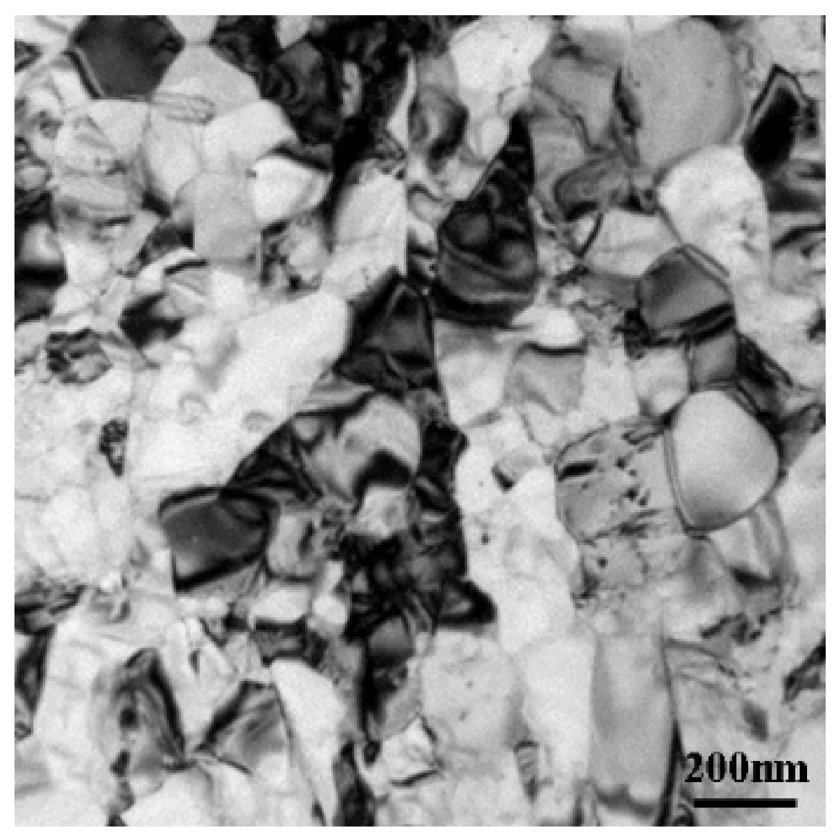
Figure 4.
Scanning electron microscopy (SEM) fractographs of 304 ASS annealed at (a) 700 °C; (b) 820 °C; (c) 870 °C; and (d) 950 °C for 60 s; and the corresponding void networks obtained by image processing on the SEM images: (e) 700 °C; (f) 820 °C; (g) 870 °C; and (h) 950 °C.
Figure 4.
Scanning electron microscopy (SEM) fractographs of 304 ASS annealed at (a) 700 °C; (b) 820 °C; (c) 870 °C; and (d) 950 °C for 60 s; and the corresponding void networks obtained by image processing on the SEM images: (e) 700 °C; (f) 820 °C; (g) 870 °C; and (h) 950 °C.


Figure 5.
Dimple size distribution after annealing at (a) 700 °C, (b) 820 °C, (c) 870 °C, and (d) 950 °C for 60 s.
Figure 5.
Dimple size distribution after annealing at (a) 700 °C, (b) 820 °C, (c) 870 °C, and (d) 950 °C for 60 s.

Figure 6.
Strength properties with average dimple diameter at different annealing temperatures.

Figure 7.
Ductility properties with average dimple diameter at different annealing temperatures.

Figure 8.
Schematic illustration of the crack propagation after the micro deformation tensile test, showing specimens annealed at 700 °C for 60 s (bidirectional arrow: stress direction).
Figure 8.
Schematic illustration of the crack propagation after the micro deformation tensile test, showing specimens annealed at 700 °C for 60 s (bidirectional arrow: stress direction).
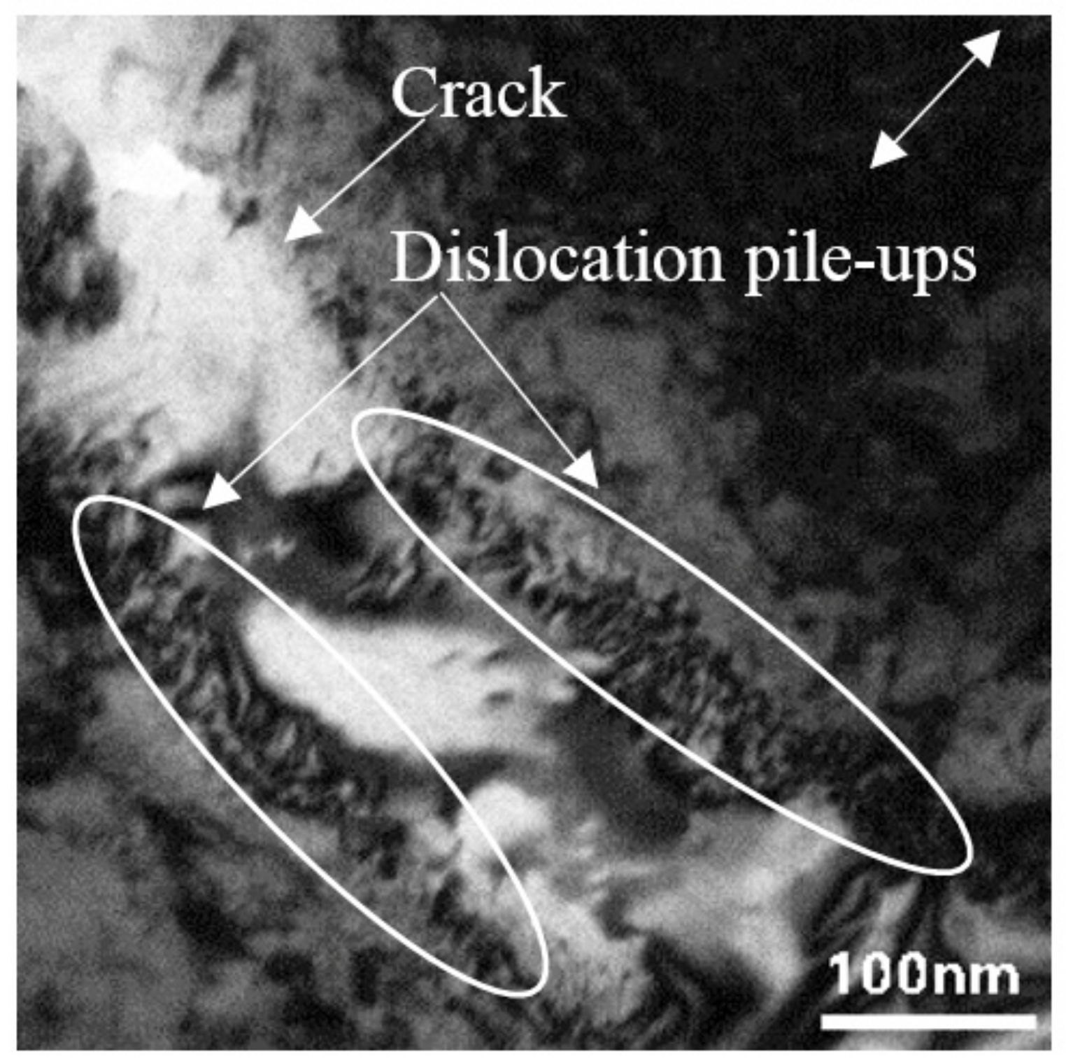
Figure 9.
Phase map of the specimen annealed at 700 °C for 60 s after micro deformation tensile test, 5–10 μm away from the crack (blue-austenite, red-martensite).
Figure 9.
Phase map of the specimen annealed at 700 °C for 60 s after micro deformation tensile test, 5–10 μm away from the crack (blue-austenite, red-martensite).

Figure 10.
TEM micrographs of specimen annealed at 870 °C after micro deformation tensile test, showing (a) irregular distribution of partial dislocations; (b) partial dislocations arranged in a row; (c) large stacking faults around ultrafine-grained (UFG) boundary; and (d) twins (bidirectional arrow: stress direction).

Figure 11.
True stress-strain tensile data for the specimen annealed at 870 °C for 60 s.
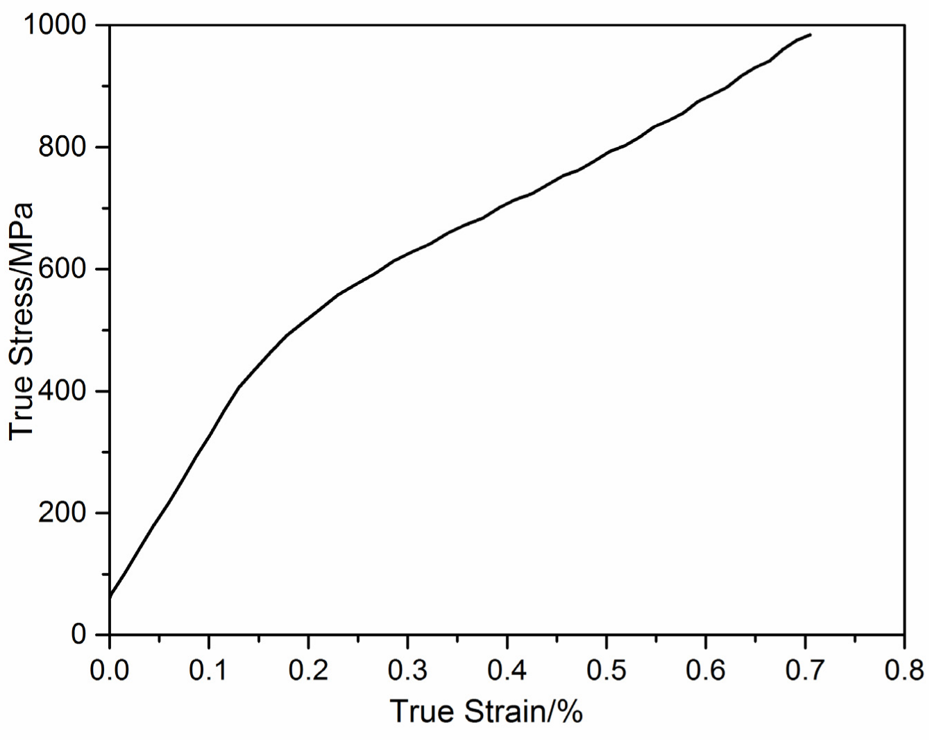
Figure 12.
Phase map of the specimen annealed at 870 °C for 60 s after micro deformation tensile test, 5–10 μm away from the crack (blue-austenite, red-martensite, yellow-ε martensite).
Figure 12.
Phase map of the specimen annealed at 870 °C for 60 s after micro deformation tensile test, 5–10 μm away from the crack (blue-austenite, red-martensite, yellow-ε martensite).

Figure 13.
TEM micrographs of specimen annealed at 950 °C after micro deformation tensile test showing (a) ε and twins observed in coarse grains; (b) dislocations in UFG structure (bidirectional arrow: stress direction).
Figure 13.
TEM micrographs of specimen annealed at 950 °C after micro deformation tensile test showing (a) ε and twins observed in coarse grains; (b) dislocations in UFG structure (bidirectional arrow: stress direction).

Figure 14.
Phase map of the specimen annealed at 950 °C for 60 s after micro deformation tensile test, 10–15 μm away from the crack (blue-austenite, red-martensite, yellow-ε martensite).
Figure 14.
Phase map of the specimen annealed at 950 °C for 60 s after micro deformation tensile test, 10–15 μm away from the crack (blue-austenite, red-martensite, yellow-ε martensite).

© 2017 by the authors. Licensee MDPI, Basel, Switzerland. This article is an open access article distributed under the terms and conditions of the Creative Commons Attribution (CC BY) license (http://creativecommons.org/licenses/by/4.0/).
Share and Cite
MDPI and ACS Style
Gong, N.; Wu, H.-B.; Yu, Z.-C.; Niu, G.; Zhang, D. Studying Mechanical Properties and Micro Deformation of Ultrafine-Grained Structures in Austenitic Stainless Steel. Metals 2017, 7, 188. https://doi.org/10.3390/met7060188
AMA Style
Gong N, Wu H-B, Yu Z-C, Niu G, Zhang D. Studying Mechanical Properties and Micro Deformation of Ultrafine-Grained Structures in Austenitic Stainless Steel. Metals. 2017; 7(6):188. https://doi.org/10.3390/met7060188
Chicago/Turabian StyleGong, Na, Hui-Bin Wu, Zhi-Chen Yu, Gang Niu, and Da Zhang. 2017. "Studying Mechanical Properties and Micro Deformation of Ultrafine-Grained Structures in Austenitic Stainless Steel" Metals 7, no. 6: 188. https://doi.org/10.3390/met7060188
Note that from the first issue of 2016, this journal uses article numbers instead of page numbers. See further details here.