Multiphysics Simulation and Experimental Investigation of Aluminum Wettability on a Titanium Substrate for Laser Welding-Brazing Process

Process and Engineering in Mechanics and Materials (PIMM) Laboratory, UMR 8006 CNRS–ENSAM, 75013 Paris, France
*
Author to whom correspondence should be addressed.
Metals 2017, 7(6), 218; https://doi.org/10.3390/met7060218
Submission received: 5 May 2017
/
Revised: 5 June 2017
/
Accepted: 9 June 2017
/
Published: 13 June 2017
(This article belongs to the Special Issue Laser Welding)
Abstract
:The control of metal wettability is a key-factor in the field of brazing or welding-brazing. The present paper deals with the numerical simulation of the whole phenomena occurring during the assembly of dissimilar alloys. The study is realized in the frame of potential applications for the aircraft industry, considering the case of the welding-brazing of aluminum Al5754 and quasi-pure titanium Ti40. The assembly configuration, presented here, is a simplification of the real experiment. We have reduced the three-dimensional overlap configuration to a bi-dimensional case. In the present case, an aluminum cylinder is fused onto a titanium substrate. The main physical phenomena which are considered here are: the heat transfers, the fluid flows with free boundaries and the mass transfer in terms of chemical species diffusion. The numerical problem is implemented with the commercial software Comsol Multiphysics™, by coupling heat equation, Navier-Stokes and continuity equations and the free boundary motion. The latter is treated with the Arbitrary Lagrangian Eulerian method, with a particular focus on the contact angle implementation. The comparison between numerical and experimental results shows a very satisfactory agreement in terms of droplet shape, thermal field and intermetallic layer thickness. The model validates our numerical approach.
1. Introduction
Assembling dissimilar alloys is widely used to reduce the weight of built structures while keeping satisfactory mechanical properties. For instance, in the aircraft industry, the material couple frequently encountered is titanium associated to aluminium. In this configuration, the titanium has better mechanical properties and is less sensitive to the corrosion attack, whereas the aluminium is 40% lighter.
The main difficulties to address when joining two dissimilar materials with conventional processes are frequently linked to the formation of intermetallic compounds. As shown by Gupta et al. [1], and confirmed by Al-Ti binary phase diagram, the aluminum has a solubility in titanium. For this reason, there is a diffusion phenomenon of the titanium into aluminium and that tends to generate intermetallic compounds, which are known to be very brittle ceramic materials that affect mechanical properties of assemblies. Moreover, the large differences in microstructures, melting temperatures and thermal properties favour the use of solid state joining methods: diffusion bonding, brazing or welding-brazing, whereas the bonding between the two materials is obtained by the diffusion of chemical species through the interface and the resulting formation of intermetallic (IM) compounds (Ti3Al, TiAl, TiAl3…) [2,3].
A lot of works presented in literature are focused on the mechanical effect of the intermetallic layer on the interface strength. On one hand, Majumdar et al. [4] and Chen et al. [5] have studied the crack initiation and growth in Ti/Al assembly, whereas Rastkar et al. [6] have addressed the hardness changes in the intermetallic layer. On the other hand, Liu et al. [7] have worked on the numerical representation of the IM phase growth.
Chen et al. have also considered the process of welding-brazing with lasers [8] and they have focused on the improvement of the interfacial layer [9].
Previous works have been carried out to try to quantify the microstructural and mechanical properties of T40/A5754 joints in overlap configuration (Figure 1) [10], also called reactive wetting [11]. The adhesion strength was characterized by the laser shock adhesion test (LASAT) and an important sensitivity to the reaction layer thickness was shown. The best mechanical results were obtained with a small intermetallic layer thickness, around 1 or 2 micrometers. Lower thicknesses do not lead to sufficient bonding and higher values produce a brittle layer which reduces global material properties. It was also observed that, due to tensio-active effects, the aluminium oxide at the surface of the melt-pool strongly reduced its wettability on a titanium substrate. The interfacial contact surface was thus reduced resulting in lower tensile and adhesion strength for the assembly. This confirms that the mechanical resistance of a heterogeneous Ti/Al assembly was dependent on both the reaction layer area and the layer thickness. The latter is directly linked to the diffusion process, i.e., to the thermal field, and the laser parameters (velocity, intensity…).
In this context, the aim of our numerical study was to compute the dynamics of the wetting process, to determine the temperature distribution T = f(x, t) at the Ti-Al interface and then to correlate it to the TiAl3 layer thickness obtained experimentally (Figure 2). In a next step, a validated model should allow for optimization of all of the Ti/Al assembly parameters.
It should be noted that the present study aims to propose a complete multiphysic simulation of complex phenomena occurring during the Ti/Al reactive-wetting process. In this paper, the physical problem was simplified and reduced to a bi-dimensional one, for which specific experimental measurements were implemented to validate numerical simulations. Nevertheless, the present numerical developments will be improved to further three dimensional studies.
This paper is divided into the following steps, after (1) a detailed description of the physical problem (heat transfer + fluid flow + mass transfer), the corresponding mathematical equations to be solved, and the main numerical conditions and assumptions, (2) the numerical results are presented and validated experimentally. An analysis of the process physical phenomena is then proposed (3) and future investigations are envisaged.
2. Experimental, Physical and Mathematical Description of the Ti/Al Reactive Wetting Assembly
2.1. Experimental Work
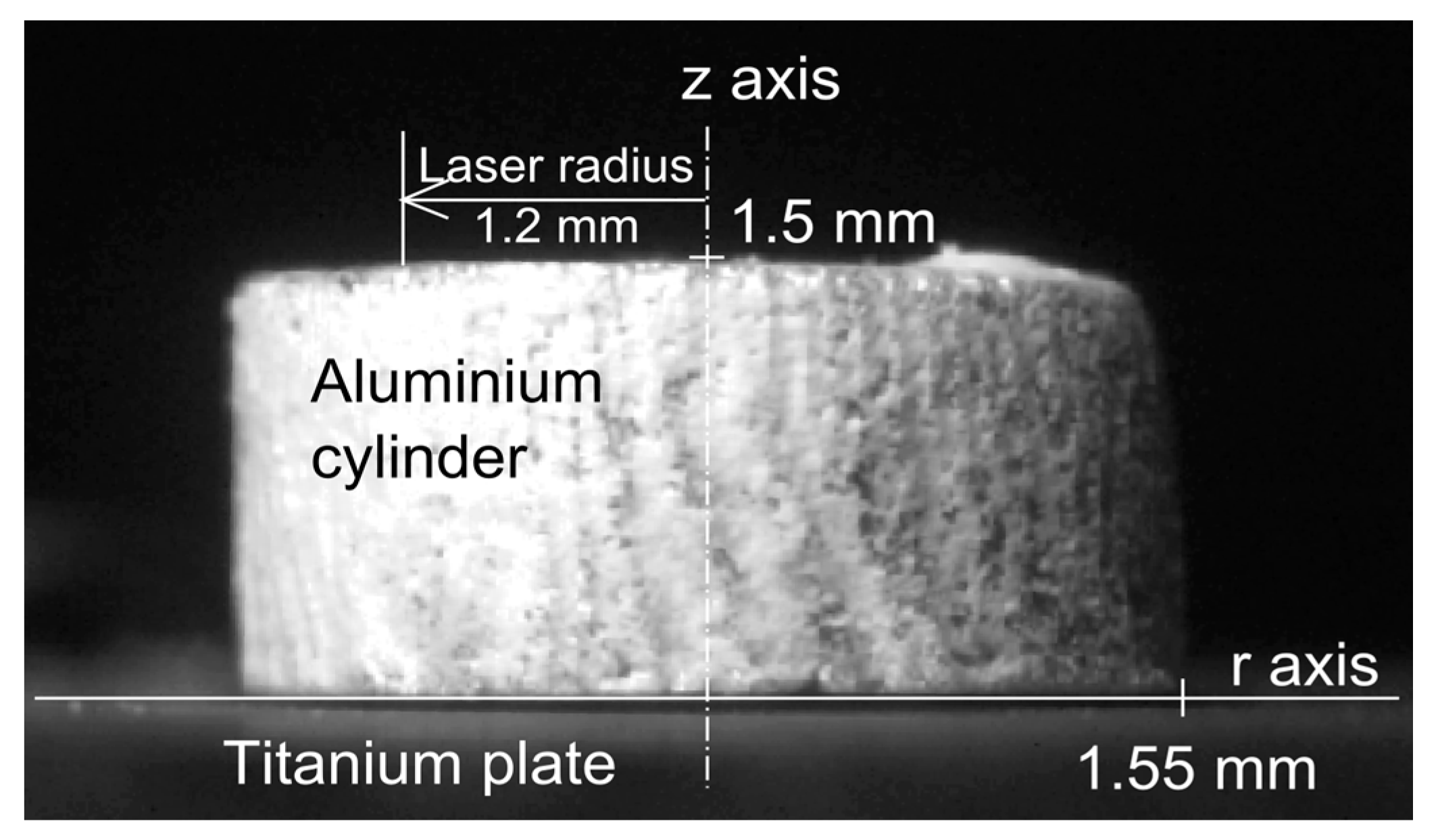
As previously indicated, the present paper is focused on a simplified Ti/Al reactive wetting assembly with a static laser irradiation. Indeed, before envisaging a more complex 3D simulation of the process, a preliminary study had to be made to ensure the validity of our thermo-hydraulic model. Moreover, in an overlap configuration, a specific focus on Al over Ti wetting parameters (surface tension and wetting angle) was expected to be an important point to address, because of a direct impact on joint shape and contact area. For this reason, the present work is dedicated to the numerical simulation of a real but simplified 2D axisymmetric case (Figure 3) where a top-hat laser beam irradiates during 1 s an aluminum cylinder that wets a titanium solid sheet.
Because aluminium is extremely sensitive to oxygen and to avoid a lack of wetting due to an alumina film between aluminium and titanium, the whole cylinder was coated by a fluor-based (NocolokTM, Solvay, Bruxelles, Belgium) anti-oxidation flux before melting. The effect of fluxing on surface tension is not well known but the influence of oxygen has already been studied, among other authors, by Molina et al. [12]. They indicated a decrease of surface tension coefficient when surfacic aluminum oxide occured, in the form of isolated Al2O3 islands. The corresponding surface tensions variation with temperature (γ(T) = 0.883 − 0.185 × 10⁻³(T − 660)) were used in the present paper. Such values were confirmed by [13].
2.2. Physical Description of the Reactive Wetting Phenomenon
In this sub-section, the physical phenomena are described and the corresponding mathematical models are written.
The phenomena occurring in the axisymmetric case are mostly like those appearing during the real 3D welding-brazing process.
In a first step, the laser beam heats the upper part of the cylinder in solid state. As soon as the metal is fused, a fluid flow is generated, and the aluminium droplet starts spreading on the Ti substrate. This flow is mainly driven by the thermocapillary forces but the buoyancy forces are also present. The resulting droplet has a shape which is theoretically (Young-Laplace principle [14]) dependent on the equilibrium between the surface tension and the local pressure (Figure 4). However, considering that surface tensions are highly sensitive to the temperature and because temperature is continuously varying with time during the wetting event, the process is dynamic. Similarly, the wetting angle () is a result of the surface tensions equilibrium (Young Duprés principle [14]) at the triple point (gas, liquid and solid) but the Al droplet is moving with time. As the substrate is not perfectly smooth, a viscous dissipation is observed. The wettability is thus highly time dependent because of the temperature dependence of the surface tension. Another important phenomenon to consider is the influence of the oxidation on surface tension values, which has already been studied by Laurent et al. [15]. A large increase of the wetting angle with the oxidation rate was experimentally observed at a constant temperature.
In a last step, once the cylinder is entirely fused and exhibits a sufficient temperature level, the titanium starts diffusing directly towards molten aluminium at the beginning of the wetting, and through a thin layer of intermetallic phase in a second step [16]. Additional contributions like fluid flow at the Ti/Al interface are also expected to favour Titanium mass transfer versus aluminium.
The inter-diffusion process occurring inside the binary Ti-Al, forms different compounds, Ti3Al, TiAl, TiAl2, Ti5Al11, Ti9Al23 and TiAl3. The phase diagram of Ti-Al, leads to two main remarks, firstly, some intermetallic phases (TiAl2, Ti5Al11, Ti9Al23 and TiAl3) appear for a line concentration. Secondly, in case of titanium diffusion in aluminum the first intermetallic appearing is the TiAl3. Moreover, as reported by Sujata et al. [2], in different works, TiAl3 is the only phase formed in case of liquid aluminum reacting with solid titanium.
2.3. Mathematical Formulation
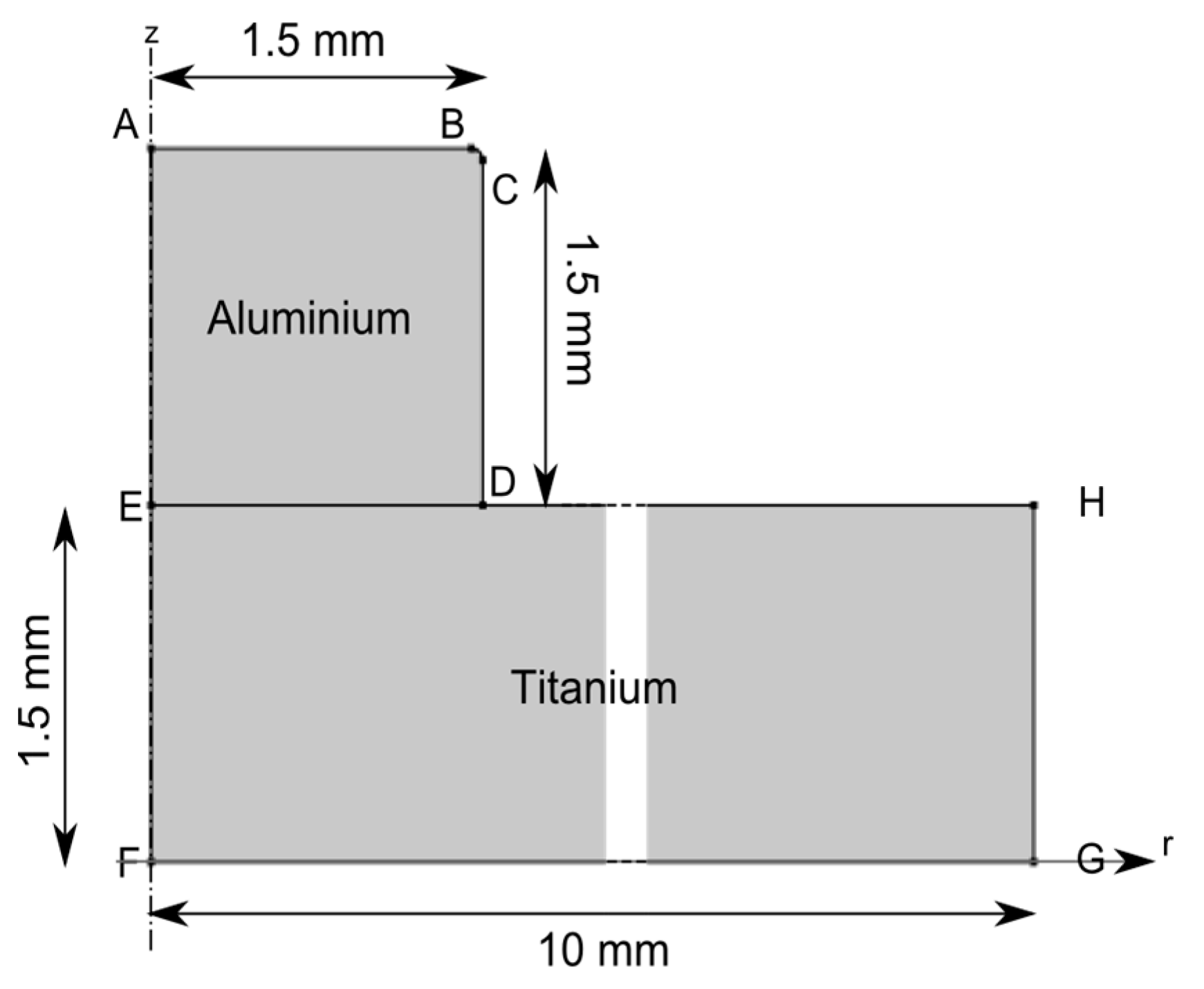
The physical problem detailed in the previous section has been addressed by solving partial differential equation (PDE) with adequate boundary conditions. The main details and assumptions of the corresponding model have been described below. The main assumption of the model is that a cylindrical coordinates system was used for the numerical calculations (simulated geometry in Figure 5), which seemed to be particularly appropriate for reproducing experiments.
2.3.1. Thermal Problem
The energy conservation PDE was solved in the whole domains (AlTi):
In this equation, is an equivalent specific heat used to account for the latent heat of fusion (Lf) [17].
The energy of phase change was thus distributed, through a Gaussian law, between the solidus and the liquidus temperatures ().
Thermal properties ( and) were assumed to be temperature dependent for both materials and were taken from the literature [18]. Since physical properties of Al 5457 and Ti40 alloys are not easily available in literature data, the properties of equivalent materials (Al 5182 and pure titanium) were considered.
An axisymmetric condition was set at AEEF:
Convective and radiative heat losses were considered at DHHGGF:
At ABBCCD, the aluminum workpiece was both irradiated by the top-hat (uniform) laser source and submitted to radiative or convective heat losses. Thus, the inward heat flux was written as:
It should be noted that, experimentally, aluminum and titanium workpieces were not perfectly in contact at the ED boundary (Figure 5). For this reason, the thermal contact between aluminum and titanium was addressed by a contact resistance (Rc) which is equivalent to a 10 µm layer of air before the fusion and 1 µm of intermetallic layer after the fusion (λair = 0.026 W·m−2·K−1 et λTiAl3 = 1.03 W·m−2·K−1 [19]). We assumed here, that the thermally-assisted diffusion of Ti to Al started just after the wetting. The interfacial condition becomes:
With ΔTi the temperature difference between the two materials at the interface.
2.3.2. Fluid Flow Problem
In order to reduce the number of degrees of freedom (DOF), the fluid flow problem was solved only in the aluminium volume. Moreover, as this material is submitted to high thermal expansion, the medium was assumed to be weakly compressible.
In the Al domain, the continuity Equation (7) and the momentum conservation (8) were solved.
where is a volumic force which includes the gravity component on the z direction.
It should be noted here that the previous Equation (8) is only suitable for Newtonian flows with Mach number smaller than 0.3; this condition is satisfied in the present case.
An axial symmetry i.e., a zero-normal velocity was set at the AE boundary.
As titanium is expected to remain at a solid state during the whole process, the real boundary condition at ED was assumed to be a flow with no slip (V = 0). However, this condition nullifies the r component of the velocity at point D whereas the motion of the free boundary surface with the ALE method needs a non-zero value. For this reason, at this boundary, a condition of wall with slip was assumed:
The no-slip condition was virtually set as follows, considering an artificial dynamic viscosity:
With H(...,..) the Heaviside function, z0 the titanium thickness and dz a smoothing length set as small as possible (the size of the first element).
The Equation (11) is composed of three parts. The first (1) corresponds to the real property of the fluid. The second (2) allows increasing the viscosity in the mushy zone and nullifying the velocity in the solid phase. The third (3) was used to stop the flow at the titanium boundary.
The motion of boundaries ABBCCD was computed with the Laplace law:
With is the local curvature of the free boundary and the surface tension assumed to be linearly dependent on the temperature:
The slope of this function is also known as the thermocapillary coefficient, responsible for the Marangoni effect.
The wetting angle was considered with a “driving” [11] or “wetting” [20] force located at the D point and written as follows:
The wetting angle () results from the equilibrium between the three surface tensions: liquid-vapour, liquid-solid and solid-vapour at the D point [14]. tf and ts, are the tangential unity vectors respectively to the liquid part and to the solid phase. While the interaction between the liquid and its vapour is well known in our case, the values of the two other surface tensions could not easily be found in the literature. Nevertheless, this parameter is very easy to observe experimentally and the few works found in the literature indicate a linear decrease of the angle with the temperature [21,22].
2.3.3. Free Boundary Motion
The domain mesh displacement and the free boundary motion were computed with the Arbitrary Lagrangian Eulerian (ALE) method [23]. This method is based upon a physical Lagrangian computation of the boundary shape (ABBCCD) and an arbitrary Eulerian calculation of the domain nodes displacement. The elements into the bulk are moved arbitrarily but with a smoothing method named “hyperelastic”. This method searches the minimum of mesh deformation energy [24].
At boundaries AE, EF and GH the displacement was set free on the z axis and set to zero on the r axis. Conversely, the motion condition at boundaries ED, DH and FG was free on r and zero on z.
The free boundaries (ABBCCD) are then moved by the computed normal velocity (Equation (15)).
With (u, w) and (nr, nz) the components of, respectively, the velocity vector and the normal vector to the boundary.
2.3.4. Mass Transfer Problem
This problem was not solved with the three others because of element sizes used for the diffusion problem (<100 nm) that leads to the resolution of a too large problem (>2,000,000 degrees of freedom). Nevertheless, as the temperature was rapidly homogeneous on all the interface aluminium/titanium, we assumed that the diffusion could be computed in 1D, along the z axis. Of course, this strong assumption will be justified in the results section.
The conservation equation that was solved here is the second Fick’s law (Equation (16)):
where is the titanium concentration and DTi/Al a temperature-dependent Arrhenian diffusion coefficient (Equation (17)):
With D0Ti/Al a pre-exponential factor and ∆H the activation energy.
As the diffusion of aluminium in the titanium is very weak (10−21 < D0Al/Ti < 10−12 m2·s−1 and ∆H > 1023 J·mol−1 [25]), we only considered the titanium diffusion towards aluminium (D0Ti/Al = 4.29 × 10⁻⁷ m2·s−1 [26] and ΔH = 180 × 103 J·mol−1 [3]). The value of activation energy here represents the diffusion of titanium in aluminium through an existing diffusion barrier, the TiAl3 layer.
As the problem is mono-dimensional, only two boundary conditions were considered: (1) at the titanium/aluminum interface, the titanium concentration was assumed to be 100% (Equation (17)) and (2) at the boundary representing the upper part of the aluminum, the titanium flux was assumed to be zero (Equation (18)).
For the initial condition, we assumed that there is no titanium in the aluminum.
2.4. Material Properties
Table 1 summarizes the main model parameters used for the calculations. Some of these values were taken from the literature. Other ones were identified experimentally and the last ones are process parameters.
2.5. Numerical Considerations
The PDE equations were solved by the finite elements method, with the commercial software Comsol Multiphysics™ (V4.4, Comsol INC, Burlington, MA, USA, 2016).
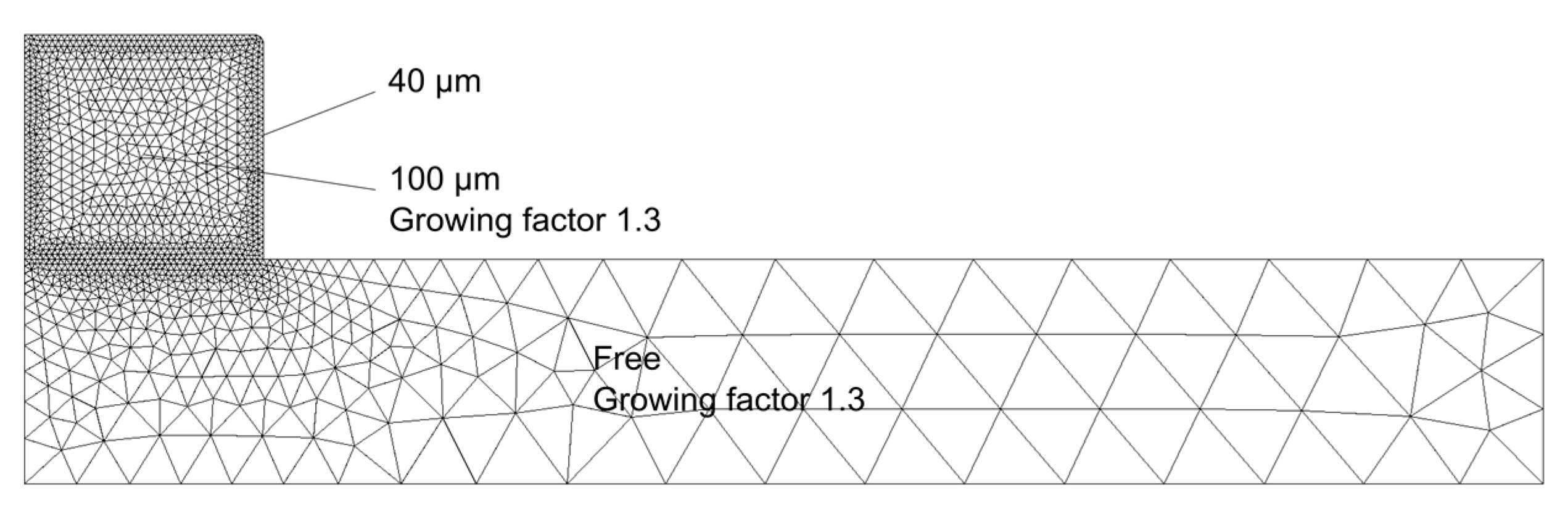
Due to the deformation of a droplet and to the remeshing process (based on the mesh quality), triangular element shapes were chosen. The mesh (Figure 6) was built in three steps. The first meshed part is the aluminium boundaries. Then, the aluminium domain and finally, the titanium domain was freely meshed. In each domain, the elements growth factor was set at 1.3. A 40 µm maximal length of boundary elements was set in order to allow a compromise between computational times and solution accuracy. It has been performed by a convergence study. Decreasing the size of mesh has no significant effect on the results (thermal and velocity fields).
Moreover, the thermal (T) and fluid flow (u, w and p) problems were solved with linear interpolations. For the ALE problem (r and z coordinates of the mesh), the geometry shape was represented with linear functions. To reduce the numerical instabilities due to linear interpolations, the calculation of velocity and pressure was stabilized by adding numerical crosswind diffusion.
This mesh leads to solve nearly 8000 degrees of freedom. A re-meshing process was used to avoid the loss of elements quality during the deformation, and each re-meshing was done when the mesh quality was below 0.2.
A fully coupled resolution was performed with the parallel sparse direct linear solver PARDISO. The numerical scheme used to solve the time-dependent problem was the implicit generalized-alpha method, and an adaptative time-stepping was used with a maximum time step of 0.0005 s. During the resolution, the use of a maximal time step value allowed for avoiding severe transition between two iterations and thus reduced time loss due to time step recalculation.
The error was controlled with an absolute tolerance of 0.01 (with the unit of each calculated variable) and a relative tolerance of 0.01%.
Such numerical conditions led to a calculation time lower than one hour for the global thermohydrodynamics process with 1.6 GHz CPU frequency on 4 threats and with 1600 MHz random access memory (on a laptop computer).
3. Results and Discussion
Before extensively using such a numerical model, we had to check the validity of its results. For this purpose, numerical solutions were compared to a dedicated Al/Ti reactive wetting experiment, where appropriate diagnostics were considered to validate or reject the numerical solution. As indicated in Section 1, the following diagnostics were used: (1) a C-Mos fast camera to monitor the droplet shape evolution with time, (2) thermocouples to measure the temperature of the titanium surface, and (3) optical micrographs to determine the reactive layer thickness.
As shown in Figure 3, a camera was positioned in front of the work-piece. This camera analysis, using a frame rate of 100 Hz, recorded the transient evolution of the droplet shape. In order to have a sufficient lighting of the work-piece, a halogen light is used.
A type-K thermocouple was spot-welded on the titanium surface (aluminium side) at a 5 mm distance from the laser beam axis (Figure 7). As the thermal measurement is quite far from the aluminium drop, the sensitivity is quite poor, and the TC data was mainly used to measure the initial temperature and to observe the diffusion through the two mediums.
Calculations were carried out using process parameters that were summarized in Table 1.
3.1. Droplet Shape Dynamics
Figure 8 shows a comparison between the experimental and numerical droplet shape variation with time. For each time step, the simulated droplet is placed besides the corresponding experimental picture. The numerical model is shown to provide a satisfactory agreement with fast droplet distortions.
Figure 6 shows three steps in the droplet behaviour. (1) the fusion process occurs until t = 0.15 s, then (2) a spheroidisation is observed between t = 0.15 s and t = 0.25 s and (3) an increase of wetting appears until the end of the shot.
At t = 0.1 s the camera observation allows distinguishing between the three classical zones: the liquid phase (on the top), an intermediate zone (probably not exactly the mushy zone) and the solid phase (at the bottom). Simulation results clearly show the isothermal lines corresponding to the solidus temperatures, which correspond quite well to camera observations. Similar conclusions can be found at 0.15 s time for the transition between liquidus and intermediate zone. In this picture, only two parts are shown: the liquid (which exhibits a mirror-like surface aspect) and a partially oxidized liquid zone (the bottom). Both wetting times globally validate the transient thermal field, and confirm macroscopically the thermal assumptions of the model.
In Figure 8, arrows are used to show the convection flow. The first step corresponds to the initiation of convection flow at the droplet surface by the Marangoni convection (thermocapillary effect). The second step is the creation of two convective cells, moving with time inside the droplet contour.
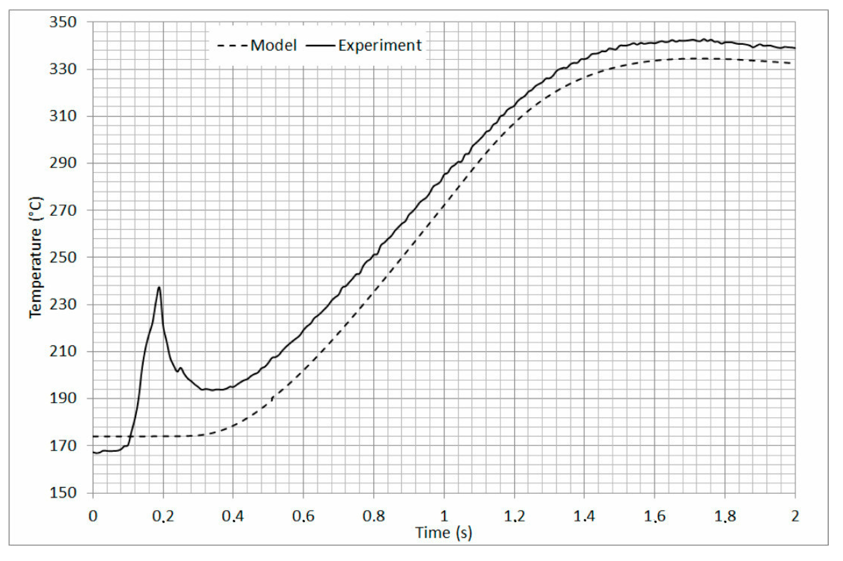
3.2. Thermal Validation
Figure 9 shows a comparison of experimental and numerical temperature versus time thermal cycles, considering one point of the titanium substrate, 5 mm distant from the laser beam axis (cf. Figure 7). A rather good agreement can be shown between numerical and experimental results. Both the dynamic evolution with time and the maximum amplitude are well reproduced by the model, except concerning the first temperature peak observed experimentally for the short times (between 0.1 and 0.3 s), which is attributed to a laser beam reflexion towards the thermocouple. Indeed, this time interval corresponds to the high droplet deformation phase (transition between no-wetting and wetting, Figure 8).
3.3. Intermetallic Layer
After validating the thermal and fluid flow numerical model, the mass transfer problem was addressed, with the objective of computing the intermetallic layer thickness.
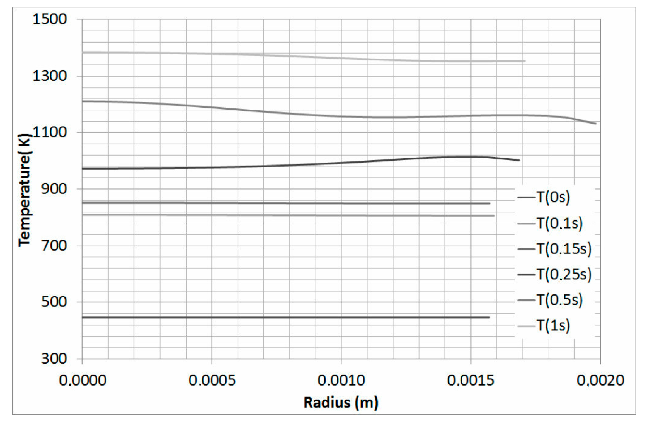
Before considering numerically, the diffusion problem we have checked the assumption concerning the thermal homogeneity of the interface. Figure 10 shows the temperature distributions along the radius for different time steps. This graph exhibits a quite homogeneous temperature distribution along the r axis, which validates afterwards our initial assumption of interfacial thermal homogeneity.
With this graph, we observe a quite homogeneous temperature along the r axis, thus our assumption seems to be realistic.
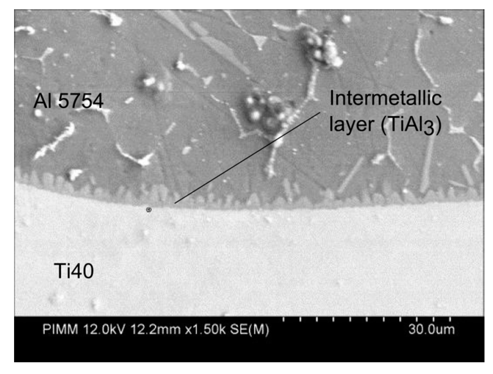
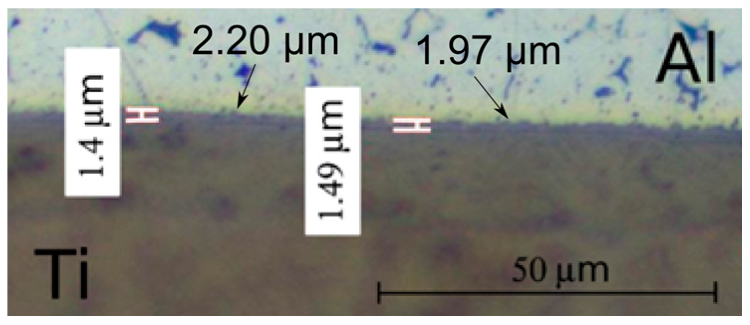
The results of the diffusional problem are shown in Figure 11 where the titanium concentration is put along the symmetry axis for different time whereas Figure 12 shows the experimentally observed layer thickness. The horizontal line shown in Figure 11 is the assumed level of TiAl3 formation (25%Ti and 75%Al). The numerical value obtained at the last time step is 2 µm. Compared to the experimental observation (1.5 µm), the numerical result was considered satisfactory, considering the assumptions made on input parameters, and especially on diffusion coefficient and activation energy.
This comparison between simulation and experiment leads to 25% of relative error in terms of intermetallic thickness. This value seems to be very high; nevertheless, it is satisfactory considering the high level of uncertainty on diffusion parameters coming from the literature. Moreover, as shown in Figure 2, the layer is very serrated thus accurate experimental measurements are very difficult. For instance, two measurements made at local maximums (arrows in Figure 12) give values higher or equivalent to the 2 µm coming from simulation.
4. Conclusions
As a conclusion, this paper gives the different steps of the reactive wetting process simulation (welding-brazing process). The full assumption and mathematical models are described and justified. A thermo-hydrodynamic problem is firstly considered and then the diffusion of species is computed. The results, in terms of thermal field, velocity field and intermetallic thickness were compared to an experiment and results are very satisfactory.
The numerical layer thickness is a little bit larger than the experimental one (0.5 µm). Nevertheless, the simulated intermetallic layer is assumed to be homogeneous on the whole contact surface, which is not the case experimentally. While the aspect of intermetallic grain growth should be introduced in the model in order to obtain these level of details, the numerical resources available do not allow us to treat it. Indeed, the scale difference between the thermal problem (millimeter) and the diffusion problem (micrometer) and the resulting mesh lead to a large problem. That is why the uncoupled resolution looks to be the current best solution.
In future works, this method will be applied to the real welding-brazing case (overlap configuration) which means that the geometry will be three dimensional. The results will help the process user to set coherent process parameters.
Acknowledgments
The authors are very grateful to the Carnot institute for financial support.
Author Contributions
Patrice Peyre conceived, designed and performed the experiments; Morgan Dal analyzed the data, conceived the model, and performed the simulation; Morgan Dal wrote the paper.
Conflicts of Interest
The authors declare no conflict of interest.
References
- Gupta, S.P. Intermetallic compounds in diffusion couples of Ti with an Al-Si eutectic alloy. Mater. Charact. 2003, 49, 321–330. [Google Scholar] [CrossRef]
- Sujata, M; Bhargava, S.; Sangal, S. On the formation of TiAl3 during reaction between solid Ti and liquid Al. J. Mater. Sci. Lett. 1997, 16, 1175–1178. [Google Scholar]
- Wang, T.; Lu, Y.X.; Zhu, M.L.; Zhang, J.S. Identification of the comprehensive kinetics of thermal explosion synthesis Ti + 3Al → TiAl3 using non-isothermal differential scanning calorimetry. Mater. Lett. 2002, 54, 284–290. [Google Scholar] [CrossRef]
- Majumdar, B.; Galun, R.G.; Weisheit, A.; Mordike, B.L. Formation of a crack-free joint between Ti alloy and Al alloy by using a high-power CO2 laser. J. Mater. Sci. 1997, 32, 6191–6200. [Google Scholar] [CrossRef]
- Chen, Y.; Chen, S.; Li, L. Influence of interfacial reaction layer morphologies on crack initiation and propagation in Ti/Al joint by laser welding–brazing. Mater. Des. 2010, 31, 227–233. [Google Scholar] [CrossRef]
- Rastkar, A.R.; Parseh, P.; Darvishnia, N.; Hadavi, S.M.M. Microstructural evolution and hardness of TiAl3 and TiAl2 phases on Ti–45Al–2Nb–2Mn–1B by plasma pack aluminizing. Appl. Surf. Sci. 2013, 276, 112–119. [Google Scholar] [CrossRef]
- Liu, J.P.; Luo, L.S.; Su, Y.Q.; Xu, Y.J.; Li, X.Z.; Chen, R.R.; Guo, J.J.; Fu, H.Z. Numerical simulation of intermediate phase growth in Ti/Al alternate foils. Trans. Nonferr. Met. Soc. China 2011, 21, 598–603. [Google Scholar] [CrossRef]
- Chen, S.; Li, L.; Chen, Y.; Huang, J. Joining mechanism of Ti/Al dissimilar alloys during laser welding-brazing process. J. Alloys Compd. 2011, 509, 891–898. [Google Scholar] [CrossRef]
- Chen, S.; Li, L.; Chen, Y.; Dai, J.; Huang, J. Improving interfacial reaction nonhomogeneity during laser welding–brazing aluminum to titanium. Mater. Des. 2011, 32, 4408–4416. [Google Scholar] [CrossRef]
- Peyre, P.; Berthe, L.; Dal, M.; Pouzet, S.; Sallamand, P.; Tomashchuk, I. Generation and characterization of T40/A5754 interfaces with lasers. J. Mater. Process. Technol. 2014, 214, 1946–1953. [Google Scholar] [CrossRef]
- Dezellus, O. Contribution à L’étude des Mécanismes du Mouillage Réactif. Ph.D. Thesis, Institut National Polytechnique de Grenoble, Grenoble, France, 12 May 2000. [Google Scholar]
- Molina, J.M.; Voytovych, R.; Louis, E.; Eustathopoulos, N. The surface tension of liquid aluminium in high vacuum: The role of surface condition. Int. J. Adhes. Adhes. 2007, 27, 394–401. [Google Scholar] [CrossRef]
- Garcia-Cordovilla, C.; Louis, E.; Pamies, A. The surface tension of liquid pure aluminium and aluminium-magnesium alloy. J. Mater. Sci. 1986, 21, 2787–2792. [Google Scholar] [CrossRef]
- De Gennes, P.G.; Brochard-Wyart, F.; Quéré, D. Gouttes, Bulles, Perles et Ondes; Belin: Paris, France, 2005; p. 254. [Google Scholar]
- Laurent, V.; Rado, C.; Eustathopoulos, N. Wetting kinetics and bonding of Al and A1 alloys on α-SiC. Mater. Sci. Eng. 1996, A205, 1–8. [Google Scholar] [CrossRef]
- Luo, J.G.; Acoff, V.L. Interfacial Reactions of Titanium and Aluminum during Diffusion Welding. Weld. J. 2000, 79, 239–243. [Google Scholar]
- Bonaccina, C.; Comini, G.; Fasano, A.; Primicerio, M. Numerical solution of phase-change problems. Int. J. Heat Mass Transf. 1973, 16, 1825–1832. [Google Scholar] [CrossRef]
- Mills, K.C. Recommended Values of Thermophysical Properties for Selected Commercial Alloys; Woodhead Publishing: Cambridge, UK, 2002; p. 246. [Google Scholar]
- Duan, Y.H.; Sun, Y.; Lu, L. Thermodynamic properties and thermal conductivities of TiAl3-type intermetallics in Al–Pt–Ti system. Comput. Mater. Sci. 2013, 68, 229–233. [Google Scholar] [CrossRef]
- Teyssèdre, H.; Gillormini, P. Extension of the natural element method to surface tension and wettability for the simulation of polymer flows at the micro and nano scales. J. Non-Newtonian Fluid Mech. 2013, 200, 9–16. [Google Scholar] [CrossRef]
- Champion, J.A.; Keene, B.J.; Sillwood, J.M. Wetting of Aluminium Oxide by Molten Aluminium and Other Metals. J. Mater. Sci. 1969, 4, 39–49. [Google Scholar] [CrossRef]
- Han, D.S.; Jones, H.; Atkinson, H.V. The wettability of silicon carbide by liquid aluminium: The effect of free silicon in the carbide and of magnesium, silicon and copper alloy additions to the aluminium. J. Mater. Sci. 1993, 28, 2654–2658. [Google Scholar] [CrossRef]
- Hirt, C.W.; Amsden, C.C.; Cook, J.L. An arbitrary lagrangian-eulerian computing method for all flow speeds. J. Comput. Phys. 1997, 135, 203–216. [Google Scholar] [CrossRef]
- Multiphysics, C. Comsol Multiphysics Reference Manual; COMSOL: Grenoble, France, 2013; p. 1084. [Google Scholar]
- Mishin, Y.; Herzig, C. Diffusion in the Ti-Al system. Acta Mater. 2000, 48, 589–623. [Google Scholar] [CrossRef]
- Du, Y.; Chang, Y.A.; Huang, B.; Gong, W.; Jin, Z.; Xu, H.; Yuan, Z.; Liu, Y.; He, Y.; Xie, F.Y. Diffusion coefficients of some solutes in FCC and liquid Al: Critical evaluation and correlation. Mater. Sci. Eng. 2003, A363, 140–151. [Google Scholar] [CrossRef]
Figure 1.
Scheme of the welding-brazing overlap configuration.
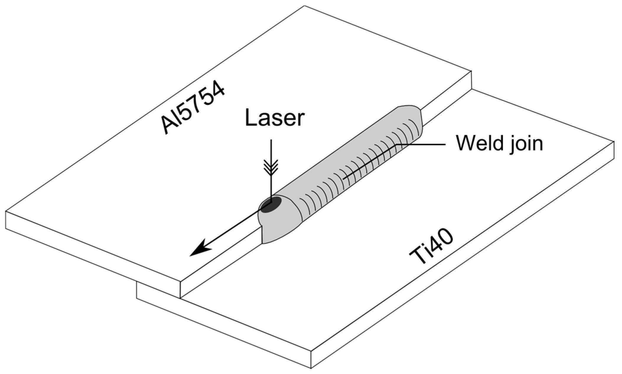
Figure 2.
Scanning Electron Microscopy analysis of TiAl3 serrated intermetallic layer.

Figure 3.
Axisymmetric experimental set-up of laser-assisted aluminum wetting on titanium.

Figure 4.
Simplified scheme of the physical phenomena involved during the fusion of an aluminium cylinder on a thin titanium substrate.
Figure 4.
Simplified scheme of the physical phenomena involved during the fusion of an aluminium cylinder on a thin titanium substrate.
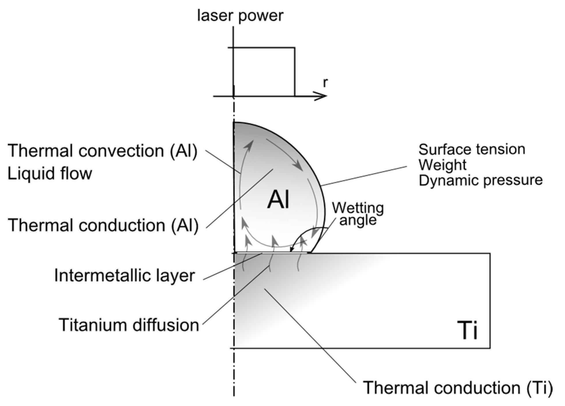
Figure 5.
Geometrical model.

Figure 6.
Mesh configuration.

Figure 7.
Experimental configuration.
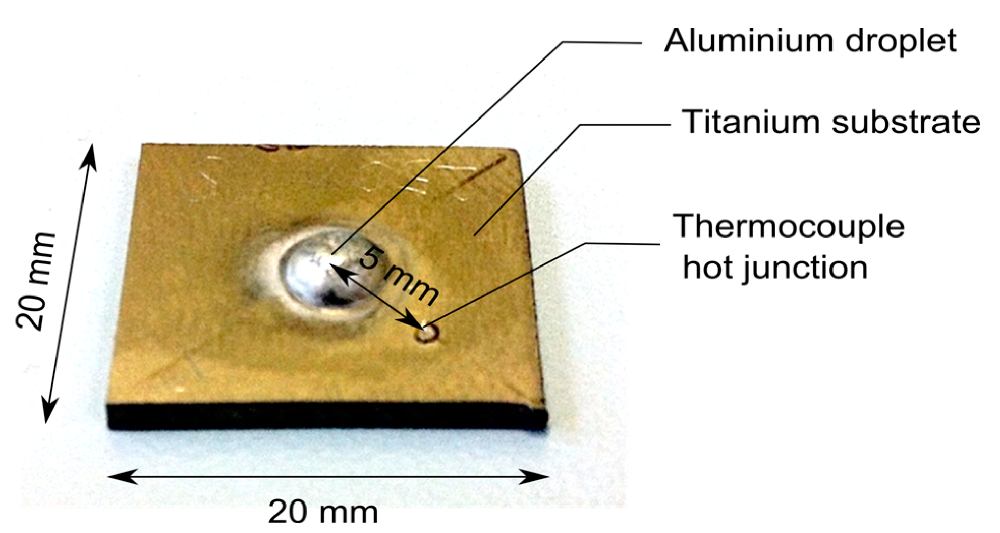
Figure 8.
Experimental and numerical shapes comparison.
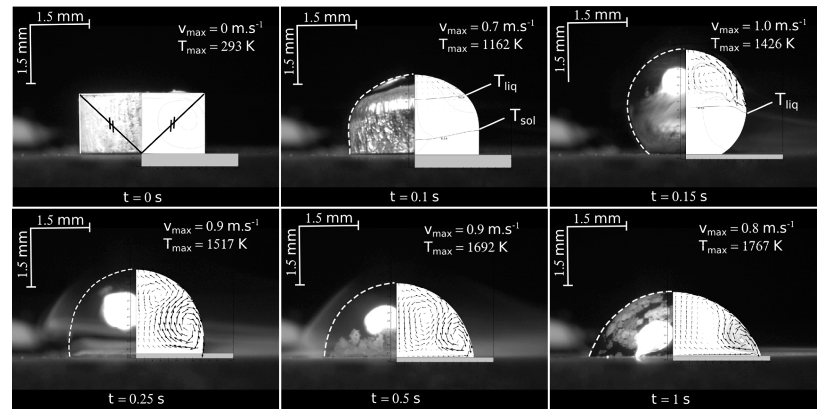
Figure 9.
Experimental and numerical temperature versus time profile at a 5 mm distance from the droplet axis.
Figure 9.
Experimental and numerical temperature versus time profile at a 5 mm distance from the droplet axis.

Figure 10.
Interface temperature distribution with time along-r radial distance

Figure 11.
Titanium concentration in aluminum along the z axis.
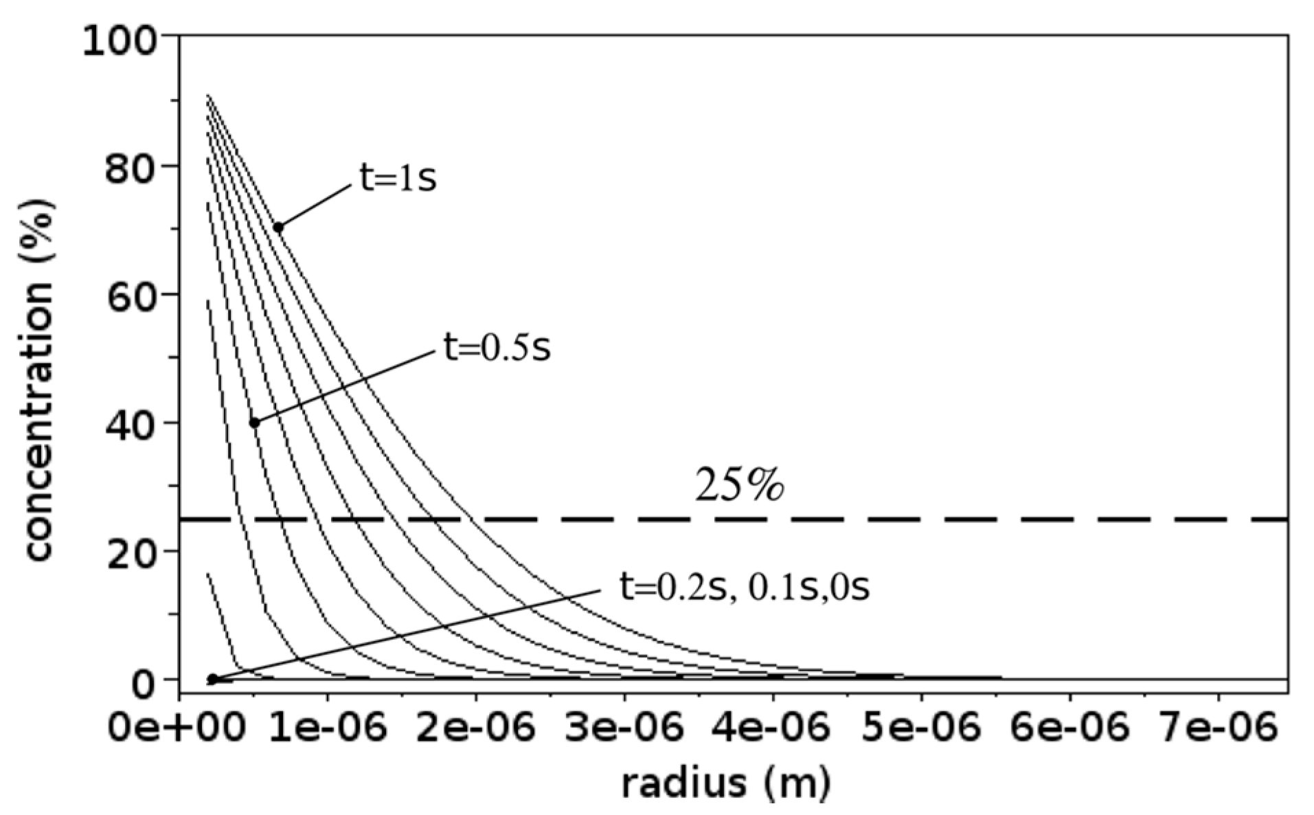
Figure 12.
Experimental measurement of intermetallic thickness.


Table 1.
Materials’ properties.
| Properties | Values/References |
|---|---|
| Thermal conductivity (Al-Ti) | λ(T) [18] |
| Specific heat (Al-Ti) | (T) [18] |
| Density (Al-Ti) | (T) [18] |
| Convective coefficient | hcv = 15 W·m−2·K−1 |
| Aluminum Absorptivity | = 0.18 |
| Aluminum Emissivity | = 0.18 |
| Titanium Emissivity | = 0.5 |
| Latent heat of fusion | Lm = 2.6 × 10⁵ J·kg–1 |
| Stefan-Boltzmann constant | = 5.67 × 10⁻⁸ W·m–2·K–4 |
| Aluminium melting range | 815–913 K |
| Titanium melting range | 1921–1941 K |
| Reference surface tension | [25] |
| Surface tension variation | = −1.44 × 10⁻⁵ N·m–1·K–1 |
| Aluminium Dynamic viscosity | = 0.0011 Pa·s |
| Contact resistance | Rc = 1 × 10⁻⁴ K·m–2·W–1 |
| Solid fraction | fsol(T) [18] |
| Laser power | 1250 W |
| Beam diameter | 2.4 mm |
© 2017 by the authors. Licensee MDPI, Basel, Switzerland. This article is an open access article distributed under the terms and conditions of the Creative Commons Attribution (CC BY) license (http://creativecommons.org/licenses/by/4.0/).
Share and Cite
MDPI and ACS Style
Dal, M.; Peyre, P. Multiphysics Simulation and Experimental Investigation of Aluminum Wettability on a Titanium Substrate for Laser Welding-Brazing Process. Metals 2017, 7, 218. https://doi.org/10.3390/met7060218
AMA Style
Dal M, Peyre P. Multiphysics Simulation and Experimental Investigation of Aluminum Wettability on a Titanium Substrate for Laser Welding-Brazing Process. Metals. 2017; 7(6):218. https://doi.org/10.3390/met7060218
Chicago/Turabian StyleDal, Morgan, and Patrice Peyre. 2017. "Multiphysics Simulation and Experimental Investigation of Aluminum Wettability on a Titanium Substrate for Laser Welding-Brazing Process" Metals 7, no. 6: 218. https://doi.org/10.3390/met7060218
Note that from the first issue of 2016, this journal uses article numbers instead of page numbers. See further details here.