Secondary Solidification Behavior of A356 Aluminum Alloy Prepared by the Self-Inoculation Method

1
State Key Laboratory of Advanced Processing and Recycling of Nonferrous Metals, Lanzhou University of Technology, Lanzhou 730050, China
2
Key Laboratory of Non-Ferrous Metal Alloys and Processing, Ministry of Education, Lanzhou University of Technology, Lanzhou 730050, China
3
Key Laboratory of Electromagnetic Processing of Materials, Ministry of Education, Northeastern University, Shenyang 110819, China
*
Author to whom correspondence should be addressed.
Metals 2017, 7(7), 233; https://doi.org/10.3390/met7070233
Submission received: 25 May 2017
/
Revised: 17 June 2017
/
Accepted: 19 June 2017
/
Published: 26 June 2017
(This article belongs to the Special Issue Microstructure and Mechanical Properties of Casting Alloys)
Abstract
:Semisolid slurry of A356 aluminum alloy was prepared by Self-Inoculation Method, and the secondary solidification behavior during rheo-diecasting forming process was researched. The results indicate that the component with non-dendritic and uniformly distributed microstructures can be produced by Rheo-Diecasting (RDC) process (combining Self-inoculation Method (SIM) with High Pressure Die Casting (HPDC)). The isothermal holding time of the slurry has large effect on primary particles, but has little effect on secondary particles. Growth rate of the primary particles in the isothermal holding process conforms to the dynamic equation of Dt3 − D03 = Kt. The suitable holding time for rheo-diecasting of A356 aluminum alloy is 3 min. During filling process, the nucleation occurs throughout the entire remaining liquid, and nuclei grow stably into globular particles with the limited grain size of 6.5μm firstly, then both α1 and α2 particles appear unstable growth phenomenon due to the existence of constitutional undercooling. The average particle sizes and shape factors of both α1 and α2 are decreasing with the increase of filling distance due to different cooling rate in different positions. The growth rate of the eutectic in RDC is 4 times faster than HPDC, which is mainly due to the limitation of α2 particles in RDC process. The average eutectic spacings are decreasing with the increase of filling distance.
1. Introduction
Semisolid metal forming is a new forming process, which uses the good rheological property of metal in the semisolid region to process components [1,2]. In the semisolid metal forming process, the primary phase is crystallized in a non-dendritic solidification mode, and the remaining liquid phases can be connected with each other, which is useful to reduce or eliminate shrinkage and thermal cracking. Meanwhile, the viscosity of the semisolid slurry is higher than the liquid, making the gas less involved. Therefore, the semisolid forming technology can obtain products without the hole-class defects in theory [3,4,5]. After half a century of exploration and research, domestic and foreign scholars have proposed the preparation process of forming semisolid slurry such as SSR (Semi-solid Rheocasting) [6], CRP (Continuous Rheoconversion Process) [7], NRC (New Rheocasting) [8], SEED (Swirled Enthalpy Equilibration device) [9], etc. Based on the characteristics of low superheat pouring, liquid-liquid mixed casting, solid-liquid mixed casting, suspension casting, and the inclined cooling method, a new type of solidification structure control method is proposed, which is called Self-inoculation Method (SIM) [10].
The solidification process of semisolid metal forming can be divided into two stages: the stage of slurry preparation (solid particles crystallize from the liquid alloy) is called primary solidification, and the solidification stage of the slurry in the forming process (solidification of the remaining liquid) is called the secondary solidification. Until recently, although the primary solidification has been extensively investigated and comprehensively understood, not much attention has been paid to the solidification of the remaining liquid after the slurry is transferred from the slurry maker to the mold. Theoretically, secondary solidification includes the crystallization of the secondary primary phase and eutectic reaction, which accompanied with the volume shrinkage and segregation problems, results in some defects such as shrinkage, hot cracking and non-uniform microstructure. Previous studies have indicated that the slurry preparation process, solid phase fraction, and cooling rate have significant effects on the solidification behavior of the remaining liquid and its microstructures. Fan et al. studied the characteristics of the secondary solidification microstructures of the remaining liquid phases of Sn–15 wt % Pb, Al–Si–Mg, and Zn–5 wt % Al alloys using the twin-screw slurry maker process [11,12,13]. It was concluded that a high shear rate and shear duration combination may promote a fine spherical morphology of the secondary solidification product. Reisi et al. [14] studied the effects of the cooling rate and solid fraction on the size of the primary phase, and it was believed that the primary particles produced in the early stage of solidification can be grown steadily, and the stable growth can be maintained in the secondary solidification stage. Zanler et al. [15] presented the results on in situ visualization of a semisolid Al–Ge alloy injected through a thin cavity and recorded by synchrotron X-ray radioscopy to study the migration of the solid and liquid phases in the semisolid state. Guan et al. [16,17] studied the solidification behavior of the remaining liquid during the extrusion process of AZ31 alloy and the rolling process of AZ91 alloy, and found that the residual liquid is obviously affected by the temperature of the process. Chen et al. [18] investigated the secondary solidification behavior of AA8006 alloy prepared by suction casting, and found that the cooling rate influenced not only the solidification of primary α-Al dendrite, but also the secondary solidification process of the remaining liquid.
Previous studies have indicated that the solidification of the remaining liquid in the semisolid slurry has an important influence on the final solidification microstructures and corresponding mechanical properties of the alloy. Therefore, it is necessary to study the solidification behavior of the secondary particles in the remaining liquid of the slurry, the eutectic reaction and their microstructural characteristics. In view of this, based on the previous studies [19,20,21,22], the thin-walled discal casting of A356 aluminum alloy was prepared by combining the semisolid slurry preparation by the self inoculation method with the traditional high-pressure die casting. The solidification behavior of the remaining liquid in rheo-diecasting of the A356 aluminum alloy was elaborated and quantitative analysis was used to investigate the secondary particles and the Si morphology in different forming positions, in order to provide a theoretical reference and technical guidance for rheo-diecasting applications of A356 aluminum alloy.
2. Experimental Details
2.1. Preparation of Self-Inoculants
The commercial A356 alloy (actual composition is shown in Table 1) was melted in a pit-type electric resistance furnance (Zhongyi Experiment Electric Stove Co., Ltd., Shanghai, China). The melt was degased by C2Cl6 (1% of the alloy mass) when the temperature of melt reached more than 720 °C, and then was cooled to 700 °C and poured into a metal mold to gain metal bars with the size of Φ 15 mm × 150 mm. Then the bars were machined into small cubes and their sizes were about 5 mm × 5 mm × 5 mm.
2.2. Slurry Preparation and Determination of Optimum Parameters
Figure 1 shows the schematic diagram of slurry preparation by SIM (self-inoculation method). In this work, the fluid director was inclined at 45° with a length of 500 mm. The commercial A356 alloy was melted in accordance with Section 2.1 and the melt temperature was adjusted to 680 °C. Then the self-inoculants (5% of alloy mass) were added into the melt and stirred quickly. After that, the mixed melt was collected through a fluid director to the collector to obtain the semisolid slurry. Finally, the prepared slurry was isothermally held for a certain time (0 min, 3 min, 5 min and 10 min, respectively) at 600 °C. Both Section 2.1 and Section 2.2 were carried out under argon protection in order to reduce the oxidation of metal melt as much as possible.
2.3. Die Casting Forming, Microstructure Observation and Quantitative Analysis
The re-prepared A356 alloy semisolid slurry with different isothermal holding temperatures determined by Section 2.2 was applied to conduct the rheo-diecasting experiment of the thin-walled part using a DAK450-54RC die casting machine (FRECH (Shanghai) Die Casting Machine Co., Ltd., Shanghai, China). The dies were preheated to 200 °C by hot circulating oil and the shot chamber was preheated to 400 °C. The piston diameter was 80 mm and the injection rate was 1.2 m/s with the pressurization of 160 MPa. The real diagram of die casting is shown in Figure 2 with the diameter of 200 mm and the wall thickness of 2 mm. In addition, the ingate thickness and length are 0.8 mm and 12.5 mm, respectively. It can be approximately calculated that the velocity of the slurry through the ingate is about 60 m/s (according to the equation: V2 = F1V1/F2, where V2 is melt velocity through the ingate, F2 is the sectional area of the ingate, V1 is the injection rate of the piston, and F1 is the sectional area of the piston). The secondary solidification behavior of rheo-diecasting was studied by the microstructures of different positions (as shown in Figure 2). The specimens were prepared by the standard technique of grinding with SiC abrasive paper and polishing with an Al2O3 suspension solution, followed by etching in saturated NaOH aqueous solution. In order to further observe the secondary particles and eutectic structures, the specimens were deep etched using the electrolytic etching method in perchloric acid alcohol solution (with a volume ratio of 1:9, the voltage of 18V and soaking time of 30–40 s). The microstructures of the specimens were observed by MFE-4 optical microscopy (OM, NIKON instruments, (Shanghai) Co. Ltd., Shanghai, China). The optimum specimen was determined by measuring the average particle sizes (D = (4A/π)1/2, where A is area of the particle) and shape factors (F = P2/(4πA), where P is the perimeter of particle) of the primary particles [20] using the image analysis software Image Proplus6.0 (Sino-Vision Technology Co. Ltd., Beijing, China). The FEG450 scanning electron microscopy (SEM, NEC Electronics Corporation, Tokyo, Japan) was carried out in an energy dispersive spectroscopy (EDS) facility and was operated at an accelerating voltage of 3–20 kV to observe the morphologies of the secondary particles and eutectic structures.
3. Results
3.1. Microstructural Differences between High Pressure Die Casting (HPDC) and Rheo-Diecasting (RDC)
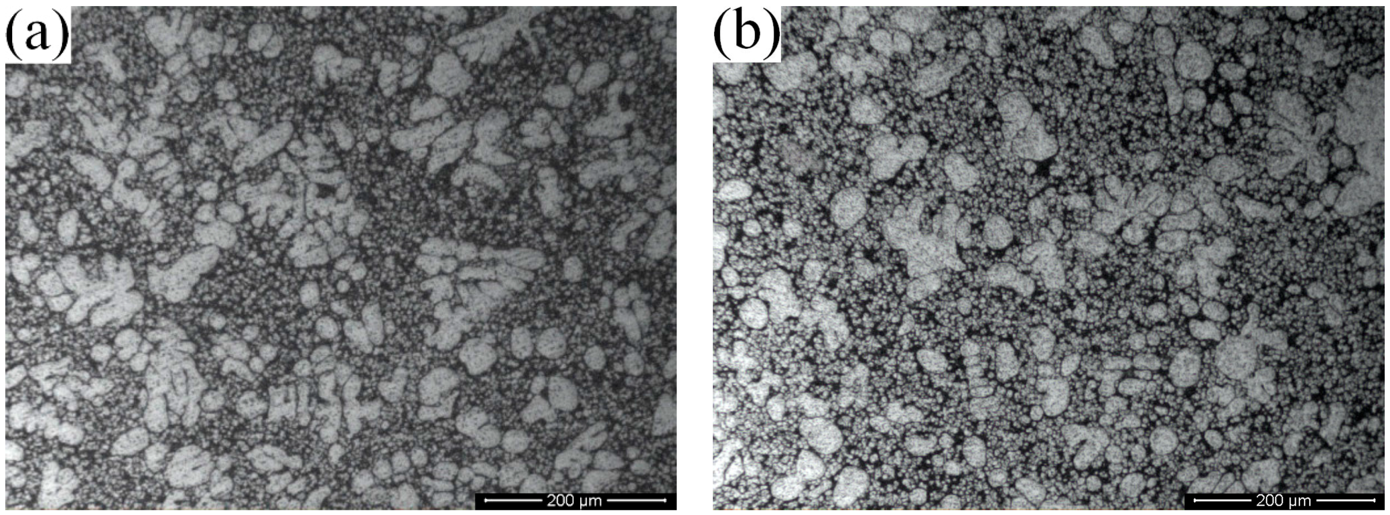
Figure 3 shows the microstructures of the A356 aluminum alloy in different forming processes. It can be seen from Figure 3a that the microstructure of the A356 aluminum alloy in liquid die-casting is mainly composed of dendritic primary α-Al and fine chilling α-Al. The morphology of the primary α-Al grains are solidified to dendritic due to the fast cooling rate and nonuniform thermal field of the liquid alloy, while the fine chilling α-Al is formed due to the outbreak of the nucleation during the filling process of the liquid phase, and has no time to grow. The microstructure of SIM rheo-diecasting is composed of spherical primary α-Al particles (α1), a small amount of dendritic fragments and fine α-Al particles called the secondary solidification particles (α2) (as shown in Figure 3b).
3.2. Effect of the Isothermal Holding Time on Primary α-Al Particles and Secondary Particles
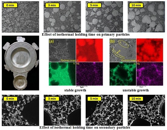
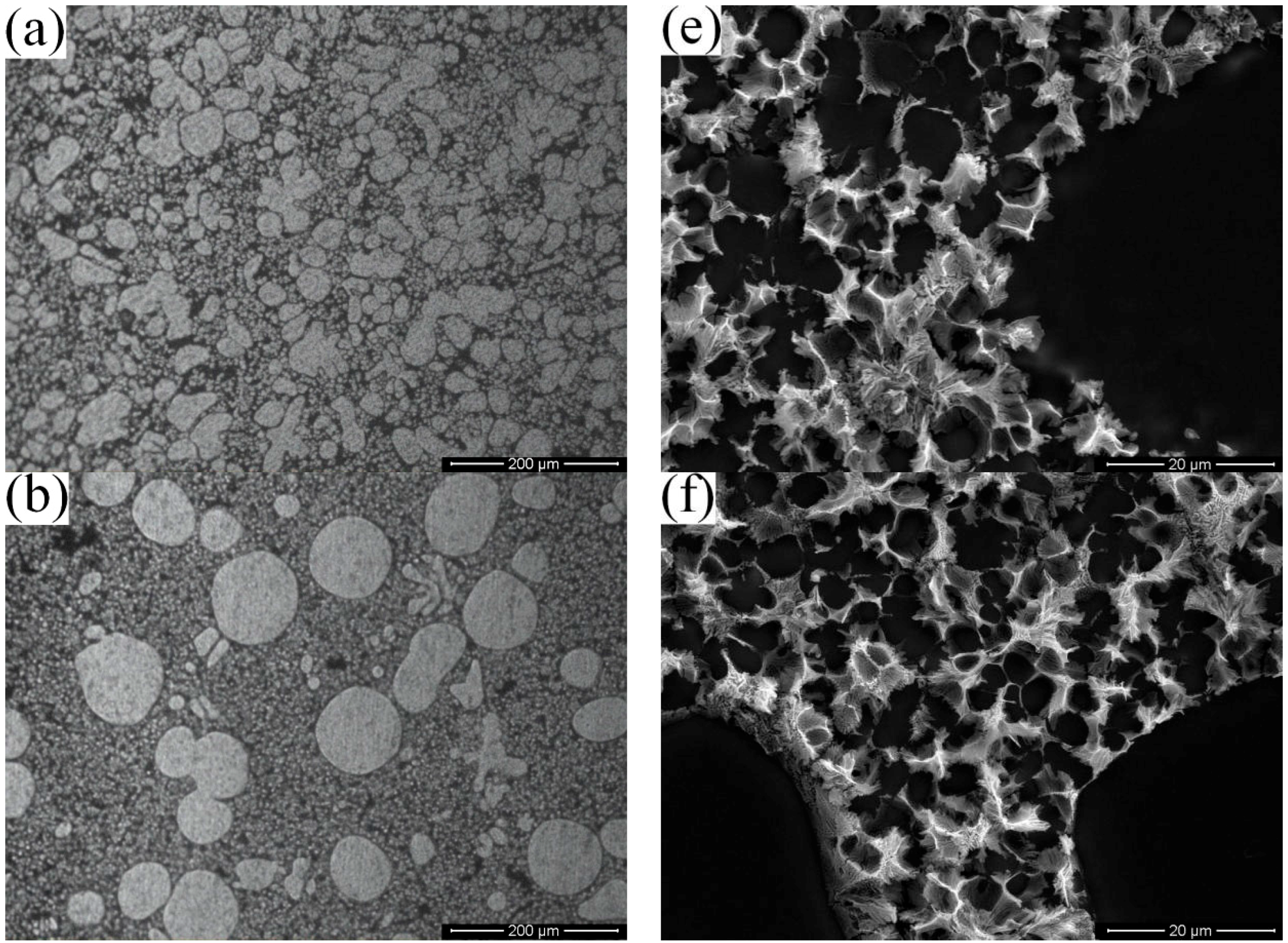
Figure 4 shows the microstructures of rheo-diecasting by SIM at different isothermal holding times (the sampling position is position D, as shown in Figure 2). It can be seen from Figure 4 that the primary particles (α1) are gradually increasing and rounding with the extension of the isothermal holding time (as shown from Figure 4a to Figure 4b), while the secondary particles (α2) from the different isothermal holding times have no obvious differences (as shown from Figure 4e to Figure 4h).
The average particle sizes and shape factors of the primary particles at different isothermal holding times are measured as shown in Figure 5a. The average particle size of the α1 in the die castings is 35 µm when the isothermal holding time of the slurry is 0 min (without holding), and the corresponding shape factor is 1.57; When the holding times are 3 and 5 min, the average grain sizes are 66 and 81 µm with the corresponding shape factors of 1.25 and 1.34, respectively; When the holding time reaches 10 min, the average grain size increased to 104 µm, and the corresponding shape factor is 1.47. It can be indicated from the fitting curve of Figure 5b that the primary particles are gradually growing and spheroidizing in the early stage of the isothermal holding process, and the growth rate of the primary particles in the isothermal holding process conforms to the dynamic equation of Dt3 − D03 = Kt [23] (where D0 is the primary solid particle diameter without isothermal holding, Dt is the average particle size after isothermal holding for t seconds, and K is the coarsening rate constant). It can be concluded from Figure 4 and Figure 5 that the primary particles can be rounded after a short isothermal holding time, while they can be degraded by a long holding time, and even some “8” shaped structures occur (as shown in Figure 4d). The suitable holding time for semisolid rheo-forming of the A356 aluminum alloy is 3 min.
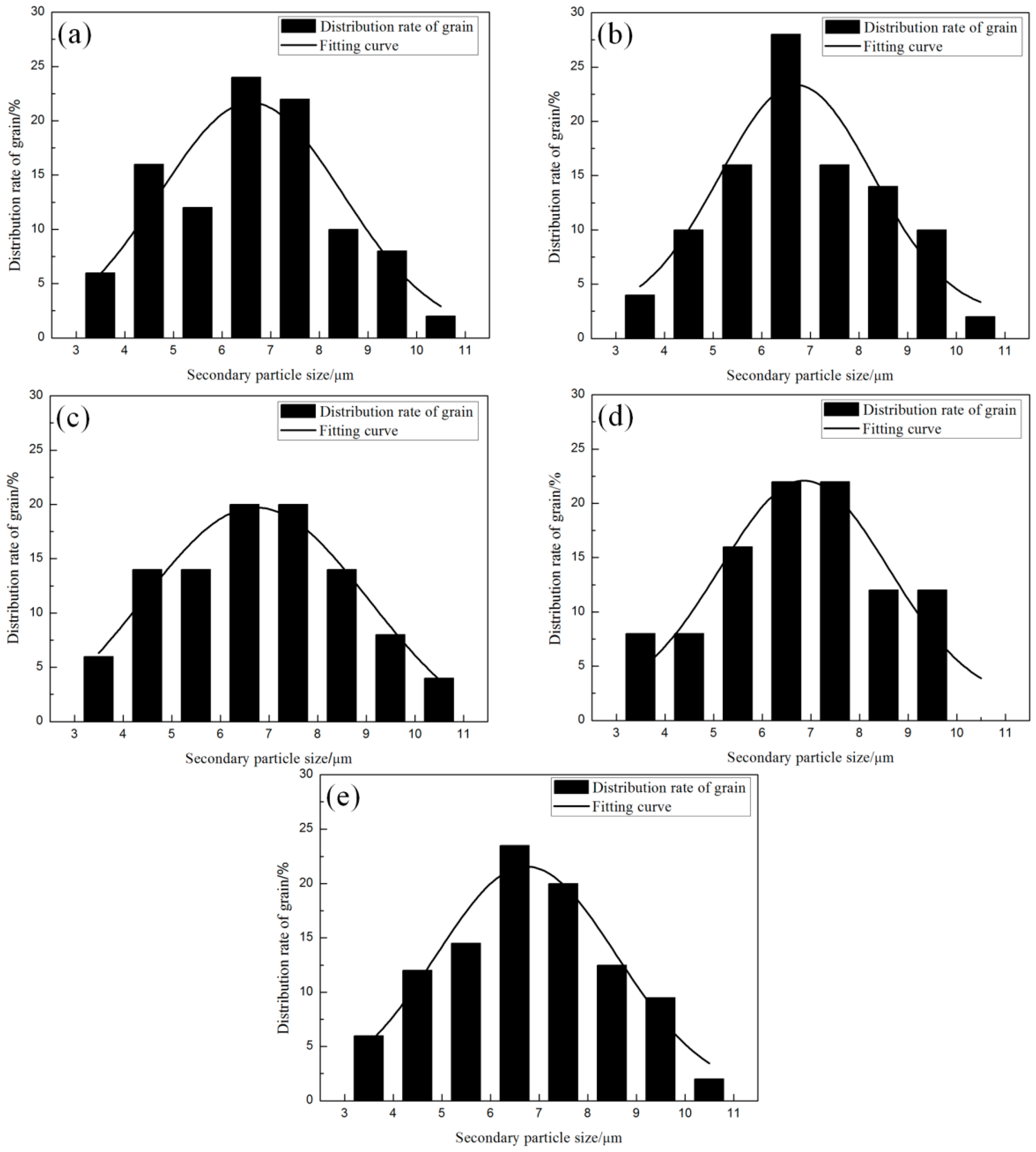
Meanwhile, it can be observed from Figure 4e–h that the morphology of the α2 particles is nearly spherical or equiaxed crystals in four parameters. The average grain size of the α2 particles were measured (50 particles for each parameter) and the results show that the average sizes of the α2 particles at 0 min, 3 min, 5 min and 10 min are 6.7 µm, 6.9 µm, 6.5 µm and 6.8 µm, respectively, indicating that the average sizes of the secondary particles with different parameters have no significant differences. The distribution of the secondary particle size with different holding parameters is shown in Figure 6. The statistical results show that the proportion of α2 particles that ranged from 5 to 8 µm are more than 50%, and the amount of α2 particles distributed in the range of 6 to 7 µm are the most. Additionally, it can also be seen from the total distribution graph (Figure 6e) that the overall distribution of the α2 particles is very similar to the size distribution and proportion of each parameter, and the proportion of the particle sizes distributed in the range of 5 to 8 µm is 58%, which can further indicate that the isothermal holding time has little effect on the α2 particle size of the thin-walled rheo-diecastings. The average grain size of the α2 particles among the four holding parameters is 6.6 µm.
3.3. Microstructures of α1 and α2 in Different Positions
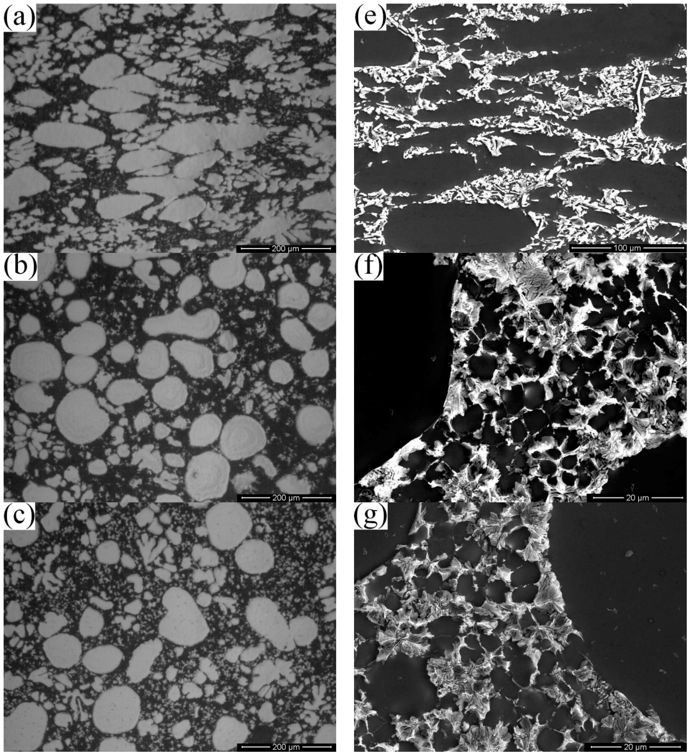
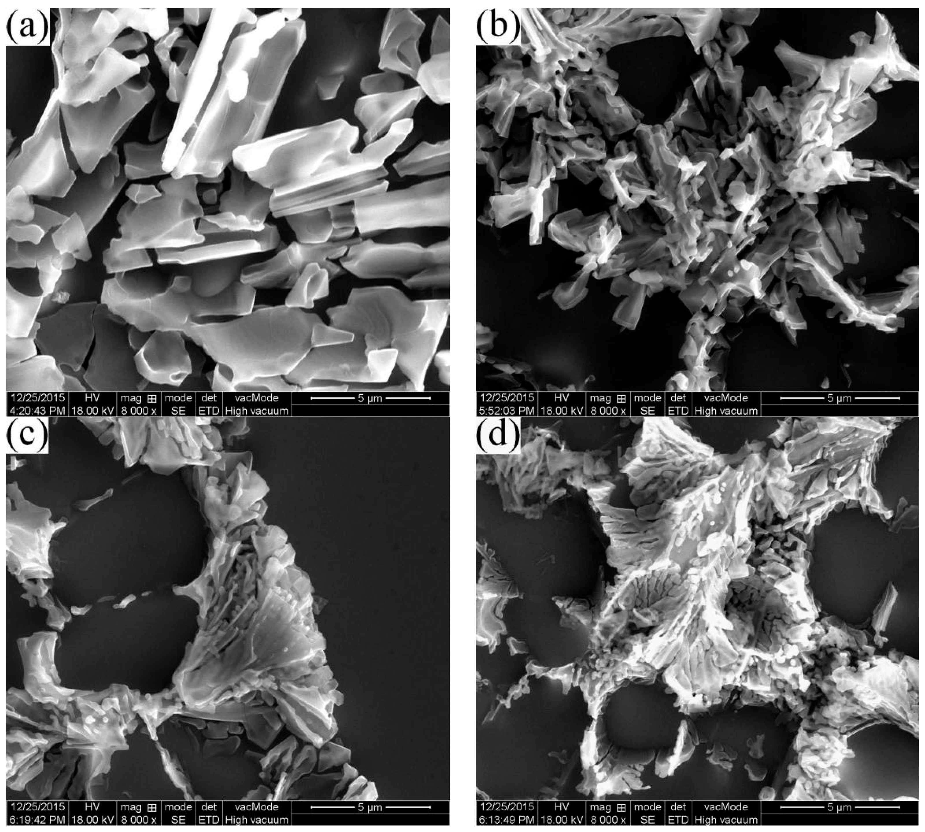
Figure 7 shows the microstructures of rheo-diecasting in different positions with the slurry isothermal holding at 600 °C for 3 min. The filling order of the semisolid slurry during die casting is from A to D (as shown in Figure 2). It can be seen that the morphologies of the primary particles are different from A to D as well as the secondary particles. In position A, the primary particles are squashed due to deformation, and the secondary particles are dendrites. In position B and C, the primary particles are more spherical than in position A. In position D, the primary particles are the roundest, as well as the secondary particles. Meanwhile, the size of the secondary particles is the smallest. Hence, it can be concluded that the microstructures in different positions of the diecasting have great differences.
Table 2 shows the measured results of the average particle sizes and shape factors of the α1 and α2 particles in different positions of diecasting. It can be seen from the measured data that the average particle sizes of both α1 and α2 are decreasing as the positions change from A to D. Similarly, the shape factors of α1 and α2 are gradually decreasing from position A to D, indicating that the filling distance has an obvious effect on the microstructures of both α1 and α2 particles.
3.4. Eutectic Structures
3.4.1. Eutectic Morphologies of HPDC and RDC
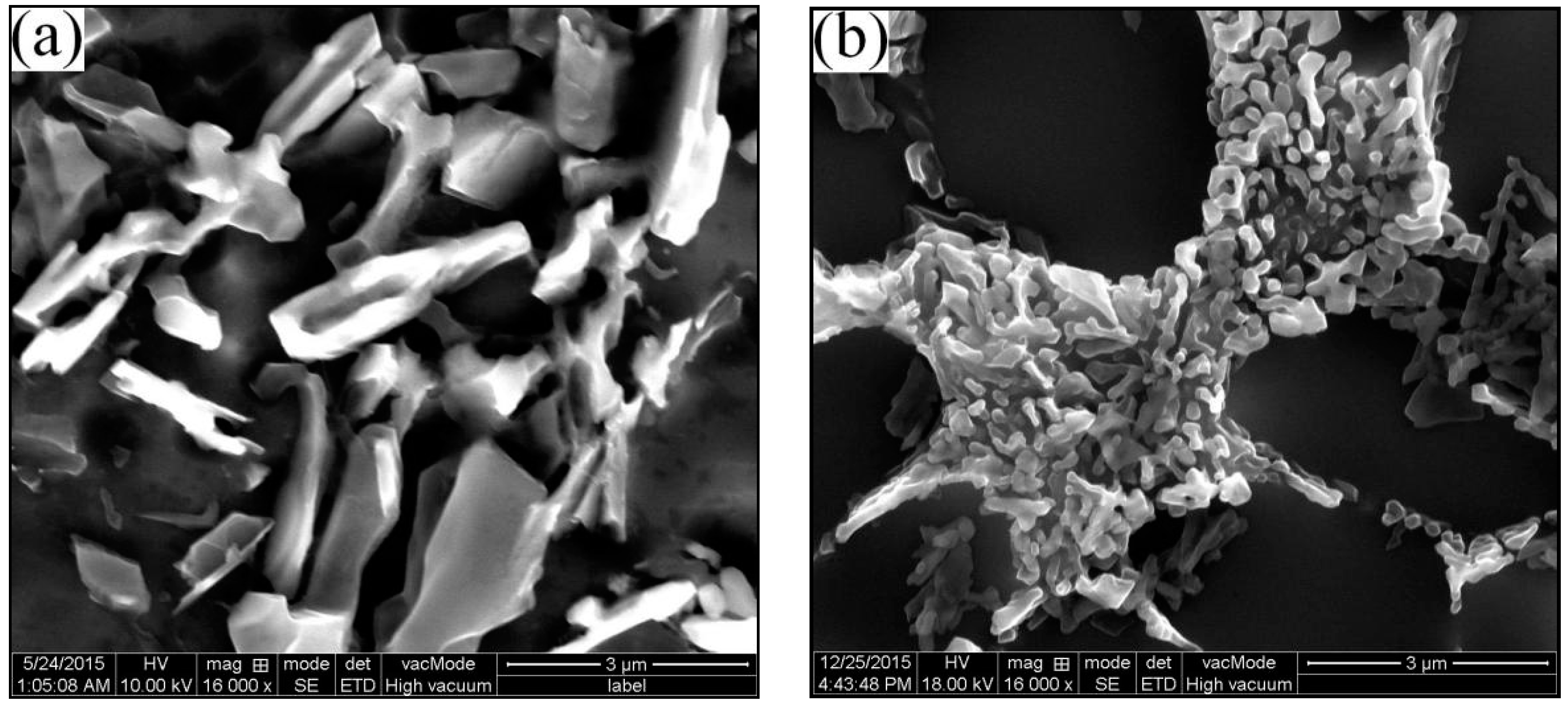
The last process of the remaining liquid during its solidification process is the eutectic reaction, and the intergranular eutectic phase is produced in this process. Usually, the eutectic Si usually displays a strong faceted behavior due to the faceted constituent of the abnormal Al–Si eutectic system, taking an irregular lamellar morphology [11]. However, it can be observed from the SEM graph of the HPDC A356 alloy that the eutectic silicon phase is block or tiny platelet, as shown in Figure 8a. In contrast, the A356 alloy of RDC prepared by the SIM process shows that the Si phase has fine fibrous or divergent chrysanthemum-like morphology, as shown in Figure 8b. Hence, the different forming process has a great effect on the morphology of the eutectic structure.
3.4.2. Morphology of Eutectic Structures in Different Positions
Figure 9 shows the morphologies of eutectic Si in different positions of die casting. It can be seen that the effect of the filling distance on the morphology of the eutectic Si is obvious. As the filling distance increases from position A to D, the eutectic structures are compacted gradually. In position A, the eutectic Si is a block structure with the largest size. The eutectic structure in position B is a small strip, and arranged more closely than in position A. In position C, the eutectic structure is a small lamellar structure with a transition tendency to a fibrous structure. While in position D, all the eutectic structures of the die casting are fine fibrous structures.
4. Discussion
4.1. Microstructural Formation of Semisolid RDC by Self-Inoculation Method (SIM)
In this experiment, the HPDC of the A356 aluminum alloy is prepared with the pouring temperature of 680 °C, which is the same as the melt treatment temperature of the semisolid slurry. When the semisolid slurry of the A356 aluminum alloy is prepared by SIM, the temperature of the A356 aluminum alloy melt will be decreased rapidly after adding the self-inoculants (about 50 °C). As the result, there will be a large number of high melting points and “large sized atomic clusters” in the local position of the melt, which will be used as the nucleation substrates. On the other hand, the addition of self-inoculants can be regarded as the addition of heterogeneous nucleation substrates in the melt, increasing the nucleation rate, which is called the process of primary inoculation. When the melt flows through the fluid director, the solidified shell is formed rapidly under the chilling of the director surface due to the low temperature of the director. Subsequently, free grains and dendritic fragments are formed and involved in the melt when the subsequent melt scours and shears the solidified shell strongly, and finally evolves into a rose-shape and fine dendritic primary particles. During this process, the temperature of the melt decreased and the undercooling of the semisolid slurry increased due to the heat transfer and convection, leading to the survival of the dendritic primary particles, which is called the process of secondary inoculation. At the end of the director, turbulence occurs when the two streams of the melt converged, which promotes the thermal field and concentration field of the melt to be homogeneous. Finally, when the slurry is collected in the accumulator, the microstructure exhibits the spherical and fine equiaxed crystals due to the fusing of the rose-like crystals. Hence, the semisolid slurry of the A356 aluminum alloy can be prepared by SIM, and the temperature of the slurry is about 600 °C. Then the slurry is poured into the shot chamber. Compared with HPDC, the pouring temperature of the RDC is lower, meaning lower supercooling and shorter solidification time. Additionally, the fine and spherical morphologies of the primary α-Al particles in the semisolid slurry exist and are uniformly distributed. Hence, the microstructures in semisolid rheo-diecasting are fine equiaxed and spherical particles instead of dendrites as in HPDC.
4.2. Effect of the Isothermal Holding Time on α1 Particles
Self-inoculation rheo-diecasting is a novel rheo-diecasting process combining the slurry preparation process by SIM with HPDC. The preparation of the fine semisolid slurry is the precondition to ensure the high quality and integrity of the die castings. When the slurry is prepared without isothermal holding, there are amounts of dendritic fragments and high melting point particles inside the melt. After collecting in the accumulator, the convection will be generated when the two streams of the melt converge, making the tip of the dendrite fragments passivated. During the isothermal holding process, the dendrite fragments are fused due to enrichment of the root solute, which lead to the formation of single irregular particles, and the tips of these irregular particles are melted. At the same time, the increased amount of particles makes the interfacial energy increase. The primary particles, as the substrates that absorb the solute atoms from the liquid phase, are rounded and spherical at the influence of the driving force-the interfacial energy can be reduced as far as possible. Consequently, the primary particles are increased and spherical with the extension of the isothermal holding time. However, the different sizes of the original dendritic fragments result in different diameters of the spherical primary particles after isothermal holding for a short time. The solute concentration of the liquid phase around the smaller particles is lower than that around the larger particles. With the further extension of the holding time, Mg and Si elements will continue to diffuse from large particles to small particles, while the Al elements have the opposite diffusion path. As a result, the large particles become larger and the small particles become smaller and even melt and disappear, which is called Oswald ripening [24]. The “8” shaped structures are formed due to the intensification of the merge phenomenon in the late stage of the isothermal holding process. When two particles with large differences in size are incorporated and grow into a new shape, the new particle will eventually be spherical under the driving force of the reduced interfacial energy. However, when two particles with the same size are merged into a new particle, it will be very difficult for the resulting particle to be spherical, and it will eventually grow into “8” shaped clusters. According to the previous experimental study, the suitable isothermal holding time of the slurry for rheological forming of the A356 aluminium alloy is 3 min. In this condition, the sizes of the α1 particles are not very large and the roundness of the particles is the best.
4.3. Formation of α2 Particles
The α2 particles are formed during the solidification process of the remaining liquid phase (secondary solidification process). When the slurry is injected into the die cavity, there are two processes in the remaining liquid, nucleation and growth. The thickness of the forming part used in the experiment is 2 mm. During the filling process, the semisolid slurry contacts with the cold mold under high pressure, which provides a large supercooling effect. The nucleation rate expression is as follows [25]:
where K is a constant, ΔG is the nucleation energy, Q is the diffusion activation energy of atoms across the liquid/solid interface, k is the Boltzmann constant, and T is thermodynamic temperature. For most of the alloy melt, the nucleation rate is significantly increased when the value of relative supercooling is between 0.15 and 0.25 Tm (Tm is the melting temperature of the alloy). The melting temperature of the A356 aluminum alloy used in this experiment is about 615 °C, while the dies are preheated to 200 °C and the pouring temperature of the alloy is 600 °C, which provides a large enough relative supercooling effect for nucleation. Therefore, nucleation occurs throughout the whole remaining liquid in the thin-walled positions.
According to the Waterloo G. [26], the cooling rate R satisfies the following equation:
where h is the heat transfer coefficient, T is the pouring temperature, T0 is the mold temperature, c the specific heat, ρ is the density, and z is the thickness of the sample, where c is 900 J/(kg·K) and ρ is 2700 kg/m3 for aluminum alloy. The mold temperature of the experiment is 200 °C and the thickness of the sample is 2 mm. According to [26,27], the value of h can arrive to 1.5 × 10⁴ Wm−2·K−1 for aluminum alloy during the thin-walled die casting process. Substituting the above values into Equation (2), the cooling rate R can reach 103 K/s. With such a rapid cooling rate, the nuclei can survive, and solidify quickly after slight growth. Therefore, the change of the thermal field and concentration field caused by the isothermal holding time has no obvious effect on the α2 particles.
4.4. Secondary Solidification Behavior
In the RDC process, due to the existence of the α1 particles, the growth of α-Al in the remaining liquid during the secondary solidification process can be divided into two methods: “attachment growth” and “nucleation growth”. Near the α1 particles, the Al atoms precipitated in the liquid phase and attach to the α1 particles [28], leading to the growth of the α1 particles. Meanwhile, nuclei after nucleation of the remaining liquid can grow into α2 particles.
In the process of secondary solidification, due to attachment growth around the α1 particles, temperature fluctuations exist at the front of the interface, and then generate perturbations ahead of the interface of the growing crystals, while most perturbations will disappear as the solidification process continues, and finally exist as a stable interface (as shown in Figure 10a). However, in some areas, the enriched layer of solute atoms will be stably generated in the liquid phase ahead of the interface, which will lead to a zone of “constitutional undercooling” ahead of the crystals. At this point, the liquid phase in this zone is in a quasi steady state, which means there is a driving force which causes the perturbations to grow. Consequently, the temperature gradient and the concentration gradient in the liquid phase will increase at the tip of the solid liquid interface, which will also make the liquid gradient increase. Finally, the zone of “constitutional undercooling” will be saved, making the perturbations around the α1 particles gradually grow into a “cellular” or “dentation” structure (as shown in Figure 10b). However, the “cellular” or “dentation” structures will be finally preserved due to the rapid cooling rate, and their sizes are smaller than the α2 particles.
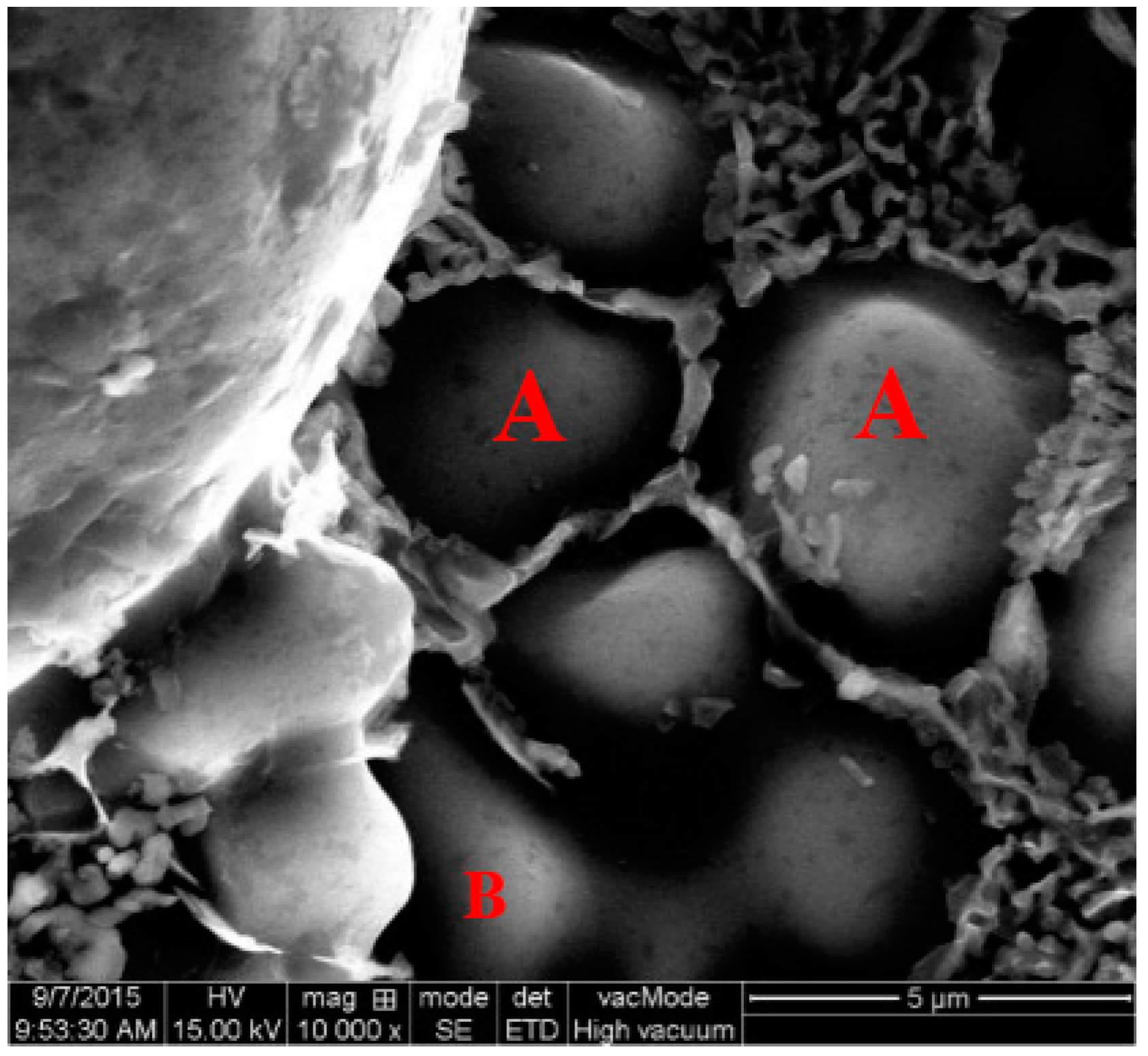
On the other hand, after the nucleation of the remaining liquid, the nucleus can stably grow into spherical α2 particles at the early stage of the solidification, while at the late stage of solidification, the α2 particles reach the limit of their stable growth and grow unstably into equiaxed crystals (point A in Figure 11). With the limit of the α1 particles during the secondary solidification process, there are also some particles that eventually grow into “8” or “shuttle” shaped particles due to the merging phenomenon of the α2 particles (point B in Figure 11).
According to the Mullins–Sekerka instability theory [29], a spherical crystal growing from a melt will grow unstably after its size arrives at a critical value Rc:
where Tm and Tl are the melting point and melt temperature, ks and kl are the thermal conductivity of the liquid and solid Al at the melting point temperature, γsl is the interfacial energy at the solid/liquid interface, Lv is the latent heat of fusion per unit volume of the solid and is a constant. Substituting the thermal–physical values of pure aluminium [11] into the above equation gives:
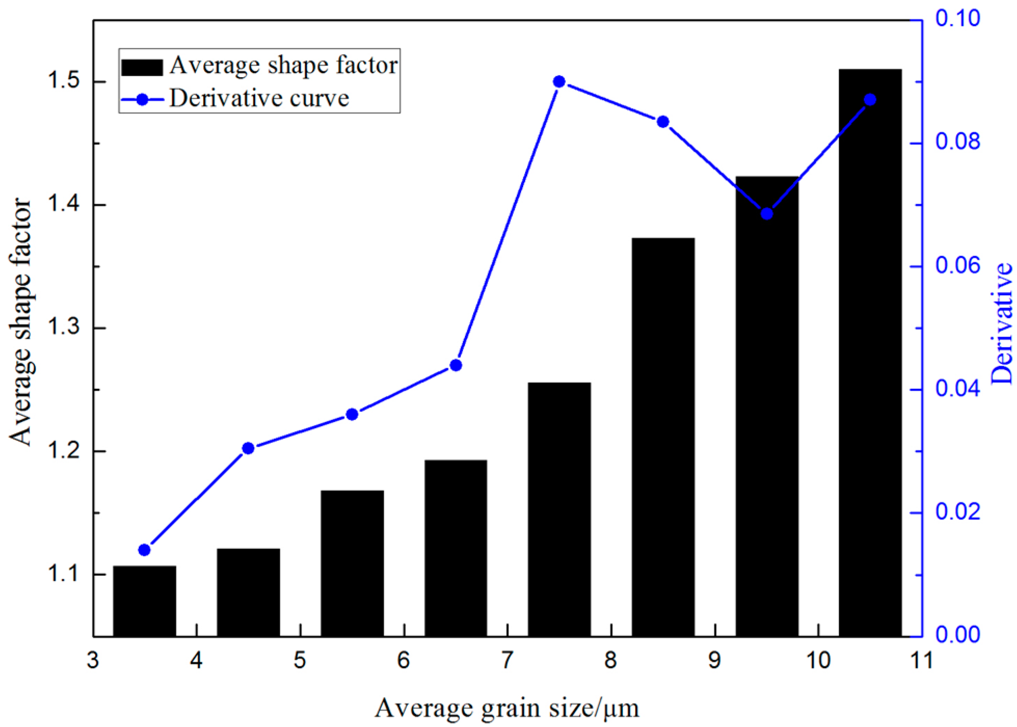
It is shown from Equation (4) that the Rc of the critical value for stable spherical growth depends on the undercooling, ∆T. In this study, the undercooling achieved by the α-Al (α2) growing from the remaining liquid inside the die cavity is difficult to directly measure, according to the existing research [30,31], and assuming a similar undercooling level, 1–2 K. During the secondary solidification process, the α-Al spherical crystals will grow stably until their diameter is 5.12–10.24 µm or larger according to Equation (4). Actually, the average α2 particle size has been measured to be 6.6 µm in diameter, indicating that the minimum undercooling of the α2 particles with spherical growth is 1.58 K. Figure 12 shows the average shape factor of the α2 particles in different size ranges. The average shape factor increases as the size of the α2 particles increase. It is indicated that the α2 particles begin with stable spherical growth, and the instability phenomenon is gradually emerging with the increase of the particle size. It can be also seen from Figure 12 that the average shape factor is between 1.1 and 1.2 when the sizes of the α2 particles are smaller than 7 μm. When the size is larger than 7 μm, the shape factor is more than 1.25. It is known that the limit size of stable growth for the α2 particles is between 6–7 μm. It is measured that the maximum size of the α2 particles during spherical growth is 6.5 µm, which is also consistent with the limit size of the α2 particles during spherical growth in Figure 12 (6–7 µm).
4.5. Effect of the Filling Distance on the α1 and α2 Particles
It is well known that liquid metal forming mainly depends on the liquid phase flow, while the semisolid metal forming depends on not only the liquid phase flow but also the solid phase flow and deformation of the primary particles in the semisolid slurry. The rheological forming process of the semisolid slurry includes four kinds of flow mechanisms: liquid phase flow mechanism, liquid solid phase mixture flow mechanism, slipping mechanism among solid particles and the deformation mechanism of the solid phase [32]. In the present work, the liquid phase flow mechanism is impossible due to the fast filling speed, and the main flow mechanism is the liquid solid phase mixture flow mechanism during the mold filling process. In this experiment, the solid fraction is lower (about 27%) so that the solid particles are dispersed and difficult to touch each other in the slurry, which makes it difficult to start the slipping mechanism among solid particles during the rheological forming process. However, due to the existence of liquid phase segregation, the amount of solid particles in some areas (such as positions A, B, and C) are increased, and as the result, the slipping mechanism among solid particles can start. When the filling process is finished, the solidification temperature of position A is higher (because the temperature of the shot chamber is higher than the cavity, and the casting thickness of position A is larger than the other positions), and the pressure is concentrated here, so the primary particles in this position are easily deformed. Meanwhile, the different temperatures between the shot chamber and dies lead to the occurrence of different cooling rates in different positions. Namely, the cooling rate from position A to position D is gradually increased due to the heat transfer from high temperature to low temperature. Its specific performance is: average particle sizes are gradually decreased from position A to position D (as shown in Table 2).
The solid fraction of aluminum alloy A356 at 600 °C is measured to be 27% by Pandat Demo (a thermodynamic calculation software, CompuTherm LLC, Middleton, WI, USA). Assuming that the alloy contains only two kinds of elements, Si and Al (because the contents of the other elements are quite small), the average solid solution of Si in the primary particles is 1.13%, which is measured by combining the equilibrium phase diagram and Pandat. According to the conservation of mass [33], the composition of the remaining liquid phase, Cl, can be expressed as:
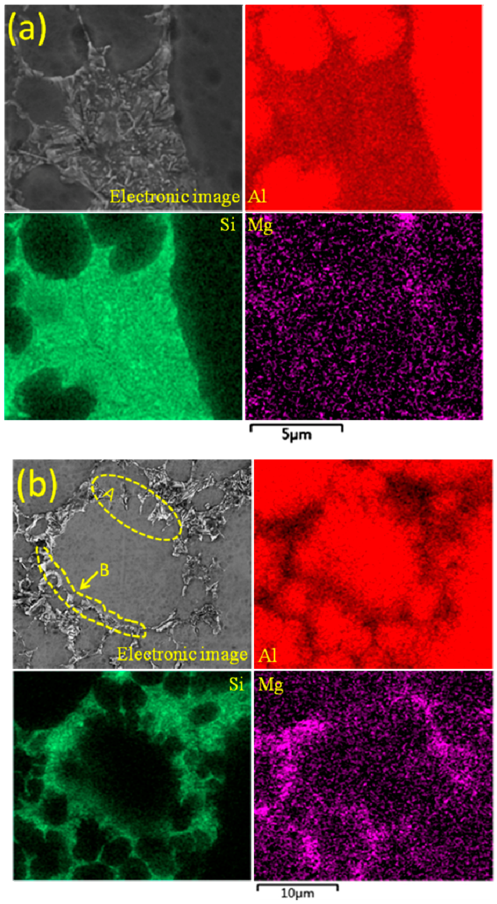
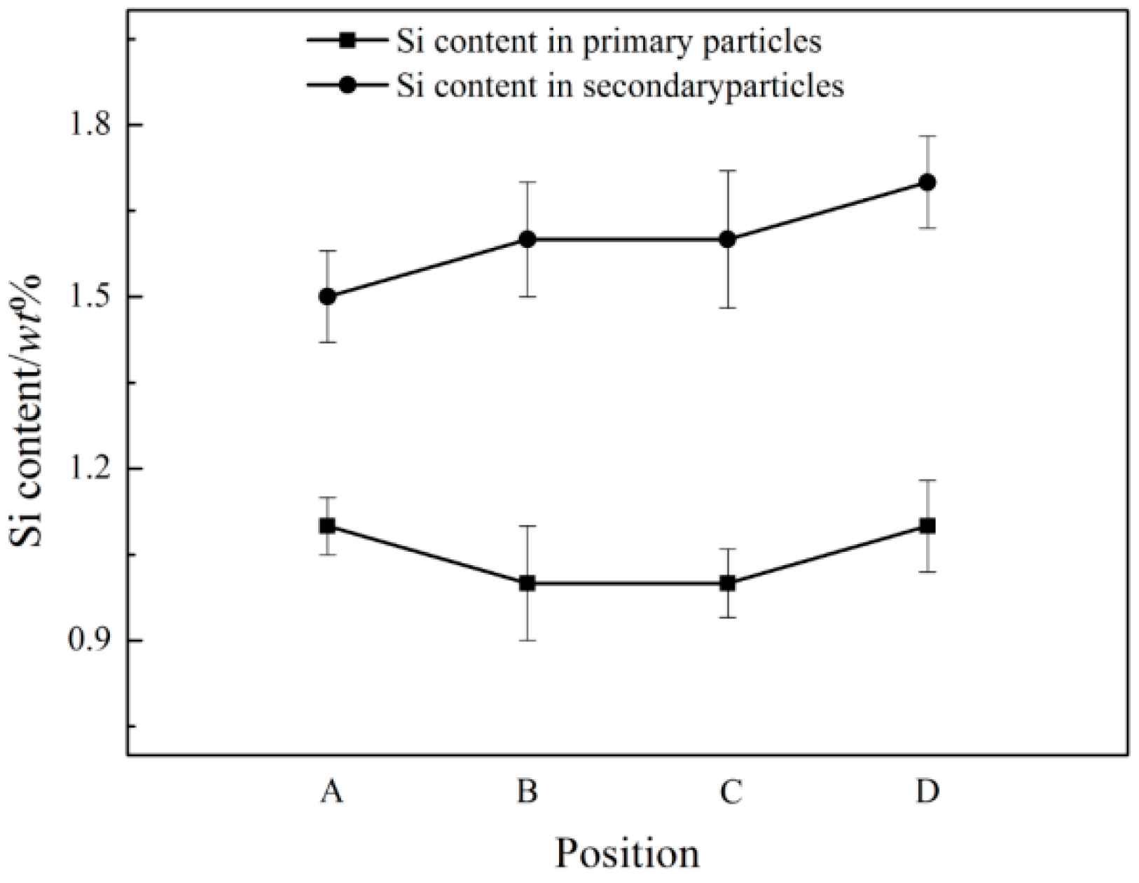
where C0 is the original content of the alloy, f is solid fraction and Cs is the composition of the solid phase. According to Equation (5), the content of Al and Si in the remaining liquid phases are 91.7% and 8.3%, respectively, indicating that the composition of the remaining liquid phase are deviated to the eutectic composition (12.6%) compared to the original composition of the alloy. The different content of Si between the primary particles and secondary particles in the experimental results indicate that the primary particles are precipitated in the original composition of the A356 alloy, while the secondary particles are formed in the remaining liquid. During the process of die casting, the rapid cooling rate (103 K/s), makes the Si atoms enriched ahead of the interface and have no time to diffuse, and eventually dissolve in the secondary particles. Consequently, the content of Si in the secondary particles is higher than that in the primary particles. The calculated value shows that the saturated solid solubility of Si in Al is 1.58%, and the measured contents of Si in the secondary particles are close to 1.58% (as shown in Figure 13). In position A, the diffusion of Si is sufficient ahead of the solid/liquid interface, which leads to a lower content of Si in the secondary particles of the final solidification microstructure. As the cooling rate increases, the diffusion of Si gradually decreases from position B to D, hence the contents of Si are gradually increasing in the secondary particles.
4.6. Formation of Eutectic Si
In the present study, the microstructure of eutectic Si in the A356 aluminum alloy undergoes a morphological change from being coarse block-like in the HPDC sample (Figure 8a) to fine fibers in the RDC sample (Figure 8b), which is mainly attributed to the high local cooling rates of the metallic die block. In the secondary solidification process of RDC, the remaining liquid is divided into very small areas due to the existence of α1 and fine α2 particles. Therefore, the eutectic reaction is confined to the small intergranular areas. Then the transition of the Si morphology can be contribute to the high local cooling rate combined with the limitation of small areas. The average eutectic spacing, λ, in the RDC and HPDC A356 alloy samples are directly measured to be 0.57 and 1.14 µm, respectively. According to the Jackson–Hunt theory of eutectic growth [34], the relationship between the eutectic spacing λ and growth velocity V is expressed as follows:
and the constant is measured to be 25.2 ± 3.2 µm2/3·s−1/2 for Al-6Si–Al-12Si alloy [35]. Substituting the above values into Equation (6) gives the eutectic growth velocity of 1489 µm/s and 372 µm/s for RDC and HPDC, respectively, indicating that the eutectic growth velocity of RDC is 4 times faster than HPDC. Moreover, the above two eutectic growth velocities are higher than 270 µm/s, which is the measured critical velocity for the morphological change [36]. Therefore, the eutectic Si grows as block or fibers instead of plates.
As for the eutectic Si in different positions, the cooling rate has a great effect on its final morphology. The cooling rate is gradually increasing from position A to D due to the different filling distances. The higher the local cooling rate, the more compact the eutectic structure. In position A, the amount of secondary particles is lower and their sizes are larger, and due to the low cooling rate, the eutectic Si has enough time and area to grow into a coarse block-like structure, while the eutectic structures are to be fine and their arrangements are gradually tightly from position B to position D as the cooling rate gradually increases.
5. Conclusions
- Compared with dendritic microstructures produced by the HPDC process, the component with non-dendritic and uniformly distributed microstructures can be produced by the RDC process (combining SIM with HPDC).
- The isothermal holding time of the slurry has a large effect on the primary particles, but has little effect on the secondary particles. The growth rate of the primary particles in the isothermal holding process conforms to the dynamic equation of Dt3 − D03 = Kt. The suitable holding time for rheo-diecasting of the A356 aluminum alloy is 3 min.
- The nucleation occurs throughout the entire remaining liquid due to the large cooling rate provided by the metallic die block. Meanwhile, the amount of Al atoms precipitated in the remaining liquid will grow and attach to the primary α-Al particles. Nuclei grow stably into globular particles with the limited grain size of 6.5 μm firstly, then both α1 and α2 particles show an unstable growth phenomenon due to the existence of constitutional undercooling.
- The average particle sizes and shape factors of both α1 and α2 decrease with the increase of the filling distance due to different cooling rates in different positions. The Si contents are gradually increasing in the α2 particles while there are no obvious differences in the α1 particles with the increase of the filling distance.
- The growth rate of the eutectic in RDC is 4 times faster than HPDC, which is mainly due to the limitation of the α2 particles in the RDC process. The average eutectic spacing decreases with the increase of the filling distance.
Acknowledgments
The authors would like to acknowledge that the project is supported by the National Natural Science Foundation of China (No. 51464031).
Author Contributions
Ming Li performed the experiments and wrote the paper under Yuandong Li’s guidance, and contributed to all activities, Xiaofeng Huang contributed analysis tools, Ming Li, Yuandong Li, Ying Ma, and Renguo Guan contributed to the interpretation and discussion of the results.
Conflicts of Interest
The authors declare no conflict of interest.
References
- Flemings, M.C. Behavior of metal alloys in the semi-solid state. Metall. Mater. Trans. A 1991, 22A, 957–981. [Google Scholar] [CrossRef]
- Luo, S.J.; Jiang, Y.Z.; Li, Y.F.; Shan, W. Recognition of Semi-Solid Metal forming technologies. Spec. Cast. Nonferr. Alloys 2012, 7, 603–607. [Google Scholar]
- Eskin, D.G.; Katgerman, S.L. Mechanical properties in the semi-solid state and hot tearing of aluminum alloys. Prog. Mater. Sci. 2004, 5, 629–711. [Google Scholar] [CrossRef]
- Xu, J.; Zhang, Z.F. Research Progress of Semisolid Processing Technology. J. Harbin Univ. Sci. Technol. 2013, 2, 1–6. [Google Scholar]
- Zhao, J.W.; Wu, S.S. Microstructure and mechanical properties of rheo-diecasted A390 alloy. Trans. Nonferr. Met. Soc. China 2010, S3, s754–s757. [Google Scholar] [CrossRef]
- Martinez, R.A.; Flemings, M.C. Evolution of particle morphology in semisolid processing. Metall. Mater. Trans. A 2005, 8, 2205–2210. [Google Scholar] [CrossRef]
- Pan, Q.Y.; Findon, M.; Apelian, D. The Continuous Rheoconversion Process (CRP). In Proceedings of the 8th International Conference on Semi-Solid Process of Alloys and Composites, Limassol, Cyprus, 21–23 September 2004. [Google Scholar]
- Kaudmann, H.; Mundi, A.; Potzinger, R.; Uggowirzer, P.J.; Ishibashi, N. An update on the new rheo-casting-development work for Al and Mg alloys. Die Cast. Eng. 2002, 4, 16–19. [Google Scholar]
- Midson, S.P. Rheocasting processes for semi-solid casting of aluminum alloy. Die Cast. Eng. 2006, 1, 48–51. [Google Scholar]
- Li, Y.D.; Yang, J.; Ma, Y. Effect of pouring temperature on AM60 Mg alloy semi-solid slurry prepared by self-inoculation method (I). Trans. Nonferr. Met. Soc. China 2010, 6, 1046–1052. [Google Scholar]
- Hitchcock, M.; Wang, Y.; Fan, Z. Secondary solidification behaviour of the Al–Si–Mg alloy prepared by the rheo-diecasting process. Acta Mater. 2007, 5, 1589–1598. [Google Scholar] [CrossRef]
- Ji, S.; Das, A.; Fan, Z. Solidification behavior of the remnant liquid in the sheared semisolid slurry of Sn–15 wt % Pb alloy. Scr. Mater. 2002, 3, 205–210. [Google Scholar] [CrossRef]
- Ji, S.; Fan, Z. Extruded microstructure of Zn–5 wt % Al eutectic alloy processed by twin screw extrusion. J. Mater. Sci. Technol. 2012, 11, 1287–1294. [Google Scholar] [CrossRef]
- Reisi, M.; Niroumand, B. Growth of primary particles during secondary cooling of a rheocast alloy. J. Alloys Compd. 2009, 1–3, 643–647. [Google Scholar] [CrossRef]
- Zanler, S.; Ershov, A.; Rack, A.; Garciamareno, F.; Baumbach, T.; Banhart, J. Particle and liquid motion in semi-solid aluminium alloys: A quantitative in situ microradioscopy study. Acta Mater. 2013, 4, 1244–1253. [Google Scholar]
- Guan, R.G.; Chen, L.Q.; Li, J.P.; Wang, F.X. Dynamical solidification behaviors and metal flow during continuous semisolid extrusion process of AZ31 alloy. J. Mater. Sci. Technol. 2009, 3, 395–400. [Google Scholar]
- Zhao, Z.Y.; Guan, R.G.; Wang, X.; Liu, C.M. Microstructure formation mechanism during a novel semisolid rheo-rolling process of AZ91 magnesium alloy. Acta Metall. Sin. 2013, 4, 447–454. [Google Scholar] [CrossRef]
- Chen, Z.W.; Zhang, H.F.; Lei, Y.M. Secondary Solidification Behaviour of AA8006 Alloy Prepared by Suction Casting. J. Mater. Sci. Technol. 2011, 9, 769–775. [Google Scholar] [CrossRef]
- Xing, B.; Li, Y.D.; Feng, J.Y.; Hu, G.S.; Tang, C.L. Rheo-Cast Microstructure and Mechanical Properties of AM60 Alloy Produced by Self-Inoculation Rheo-Diecasting Process. Metals 2016, 3, 69. [Google Scholar] [CrossRef]
- Xing, B.; Li, Y.D.; Ma, Y.; Hao, Y. Evolution of rheocast microstructure of AZ31 alloy in semisolid state. China Foundry 2013, 4, 221–226. [Google Scholar]
- Li, Y.L.; Li, Y.D.; Li, C.; Wu, H.H. Microstructure characteristics and solidification behavior of wrought aluminum alloy 2024 rheo-diecast with self-inoculation method. China Foundry 2012, 4, 328–336. [Google Scholar]
- Li, Y.D.; Zhang, X.L.; Ma, Y.; Apelian, D.; Zhou, H.W.; Liu, X.H. Effect of mixing rate and temperature on primary Si phase of hypereutectic Al–20Si alloy during controlled diffusion solidification (CDS) process. China Foundry 2015, 3, 173–179. [Google Scholar]
- Deepak, K.S.; Mihira, A.; Mandai, A.; Chakraborty, M. Coarsening kinetics of semi-solid A356–5 wt % TiB2 in situ composite. Trans. Nonferr. Met. Soc. India 2015, 6, 1075–1080. [Google Scholar] [CrossRef]
- Voorhees, P.W.; Hardy, S.C. Ostwald ripening in a system with a high volume fraction of coarsening phase. Metall. Mater. Trans. A 1988, 11, 2713–2721. [Google Scholar]
- Hu, G.X.; Cai, X.; Rong, Y.H. Fundamentals of Materials Science; Shanghai Jiao Tong University Press: Shanghai, China, 2015; Volume 3, p. 232. [Google Scholar]
- Waterloo, G.; Jones, H. Microstructure and thermal stability of melt-spun Al–Nd and Al–Ce alloy ribbons. J. Mater. Sci. 1996, 31, 2301–2310. [Google Scholar] [CrossRef]
- Guo, Z.P.; Xiong, S.M. Effects of alloy materials and process parameters on the heat transfer coefficient at metal/die interface in high pressure die casting. Acta Metall. Sin. 2008, 4, 433–439. [Google Scholar]
- Li, Y.D.; Chen, T.J.; Ma, Y.; Yan, F.Y.; Hao, Y. Microstructural characteristic and secondary solidification behavior of AZ91D alloy prepared by thixoforming. Trans. Nonferr. Met. Soc. China 2008, 1, 18–23. [Google Scholar]
- Mullins, W.W.; Sekerka, R.F. Morphological stability of a partical growing by diffusion or heat flow. J. Appl. Phys. 1963, 2, 323–329. [Google Scholar] [CrossRef]
- Burden, M.H.; Hunt, J.D. Cellular and dendritic growth. J. Cryst. Growth 1974, 2, 109–116. [Google Scholar] [CrossRef]
- Hunt, J.D.; Lu, S.Z. Numerical modeling of cellular/dendritic array growth: Spacing and structure predictions. Metall. Mater. Trans. A 1996, 27, 611–623. [Google Scholar] [CrossRef]
- Chen, C.P.; Tsao, C.Y. Semi-solid deformation of non dendritic struction—I. Phenomenological behavior. Acta Mater. 1997, 5, 1955–1968. [Google Scholar] [CrossRef]
- Yang, W.; Liu, F.; Wang, H.F.; Lu, B.P.; Yang, G.C. Non-equilibrium transformation kinetics and primary grain size distribution in the rapid solidification of Fe–B hypereutectic alloy. J. Alloys Compd. 2011, 509, 2903–2908. [Google Scholar] [CrossRef]
- Jackson, K.A.; Hunt, J.D. Lamellar and rod eutectic growth. Trans. Metall. Soc. AIME 1966, 236, 1129–1142. [Google Scholar]
- Grugel, R.; Kurz, W. Growth of interdendritic eutectic in directionally solidified Al–Si alloys. Metall. Mater. Trans. A 1987, 18, 1137–1142. [Google Scholar] [CrossRef]
- Bayraktar, Y.; Ling, D.; Jones, H. Formation and segregation of primary silicon in Bridgman solidified Al–18.3 wt % Si alloy. J. Mater. Sci. 1995, 30, 5939–5943. [Google Scholar] [CrossRef]
Figure 1.
Schematic diagram of slurry preparation by SIM (Self-inoculation Method).
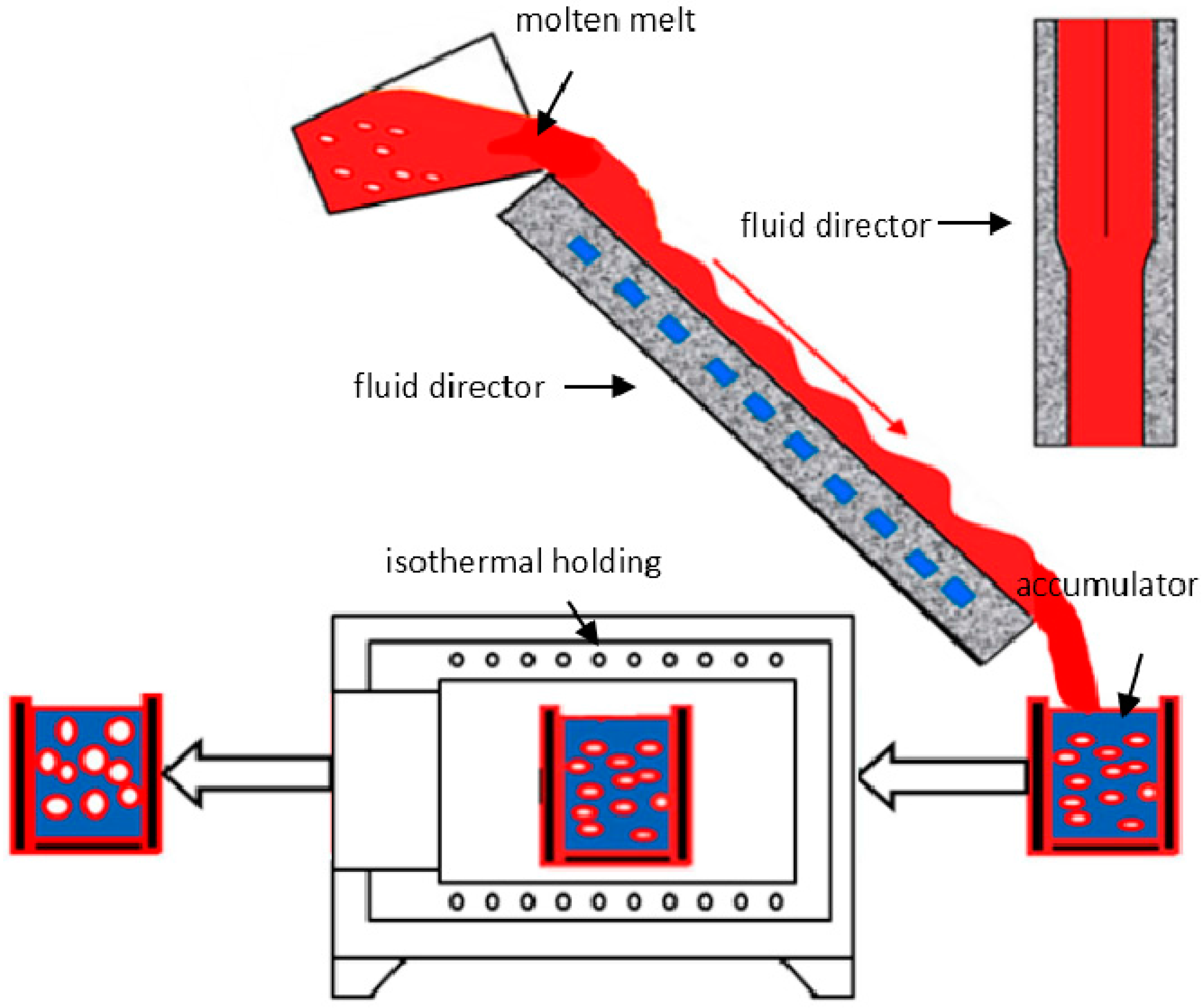
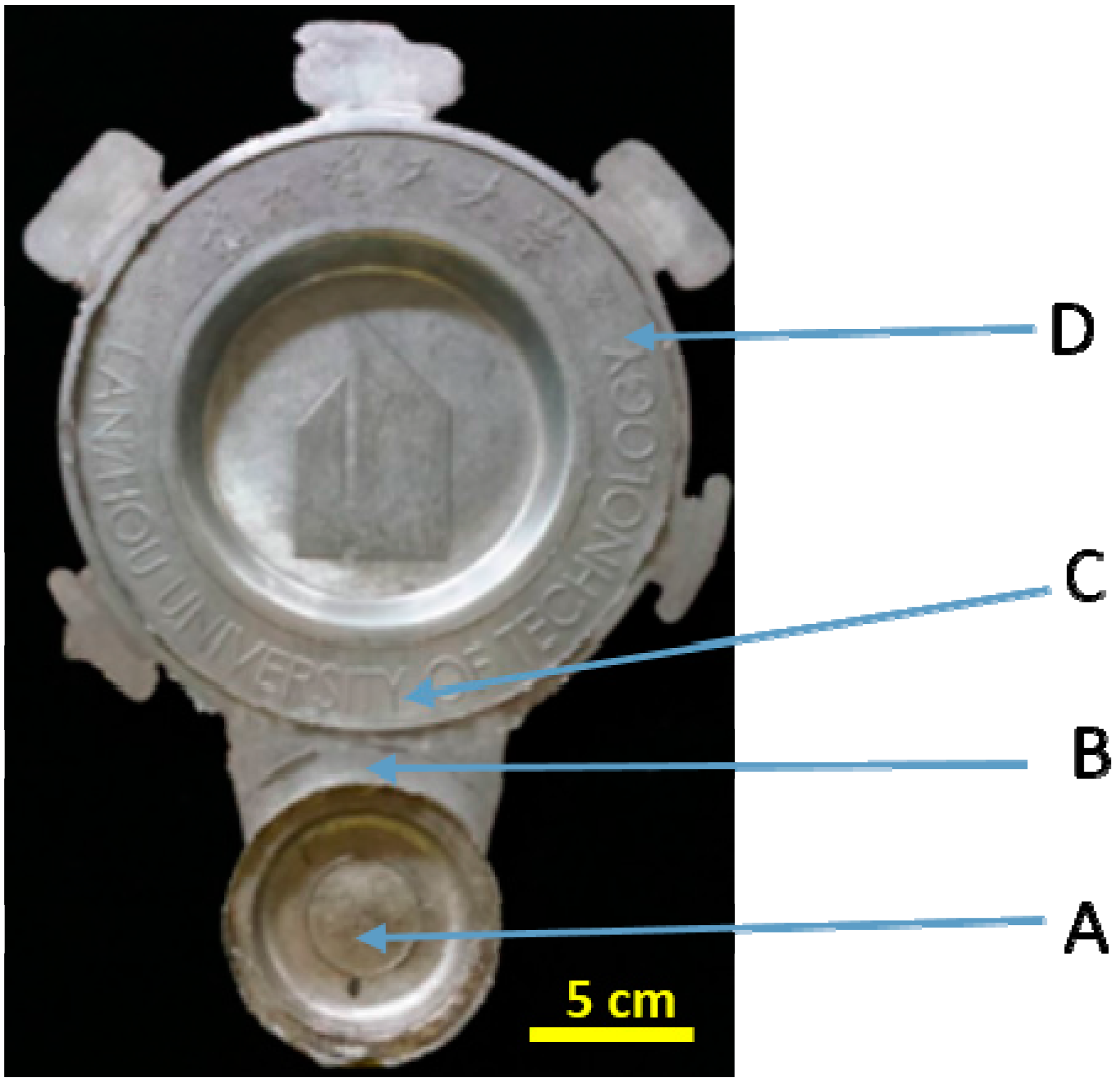
Figure 2.
Product of semi-solid die casting and the sampling positions: biscuit (A); in-gate (B); down (C) and middle (D).
Figure 2.
Product of semi-solid die casting and the sampling positions: biscuit (A); in-gate (B); down (C) and middle (D).

Figure 3.
The microstructure of A356 alloy from different forming method (a) high pressure die casting at 680 °C and (b) semi-solid rheo-diecasting by SIM.
Figure 3.
The microstructure of A356 alloy from different forming method (a) high pressure die casting at 680 °C and (b) semi-solid rheo-diecasting by SIM.

Figure 4.
Microstructure of rheo-diecasting by SIM at different holding times (a,e) 0 min; (b,f) 3 min; (c,g) 5 min and (d,h) 10 min.
Figure 4.
Microstructure of rheo-diecasting by SIM at different holding times (a,e) 0 min; (b,f) 3 min; (c,g) 5 min and (d,h) 10 min.

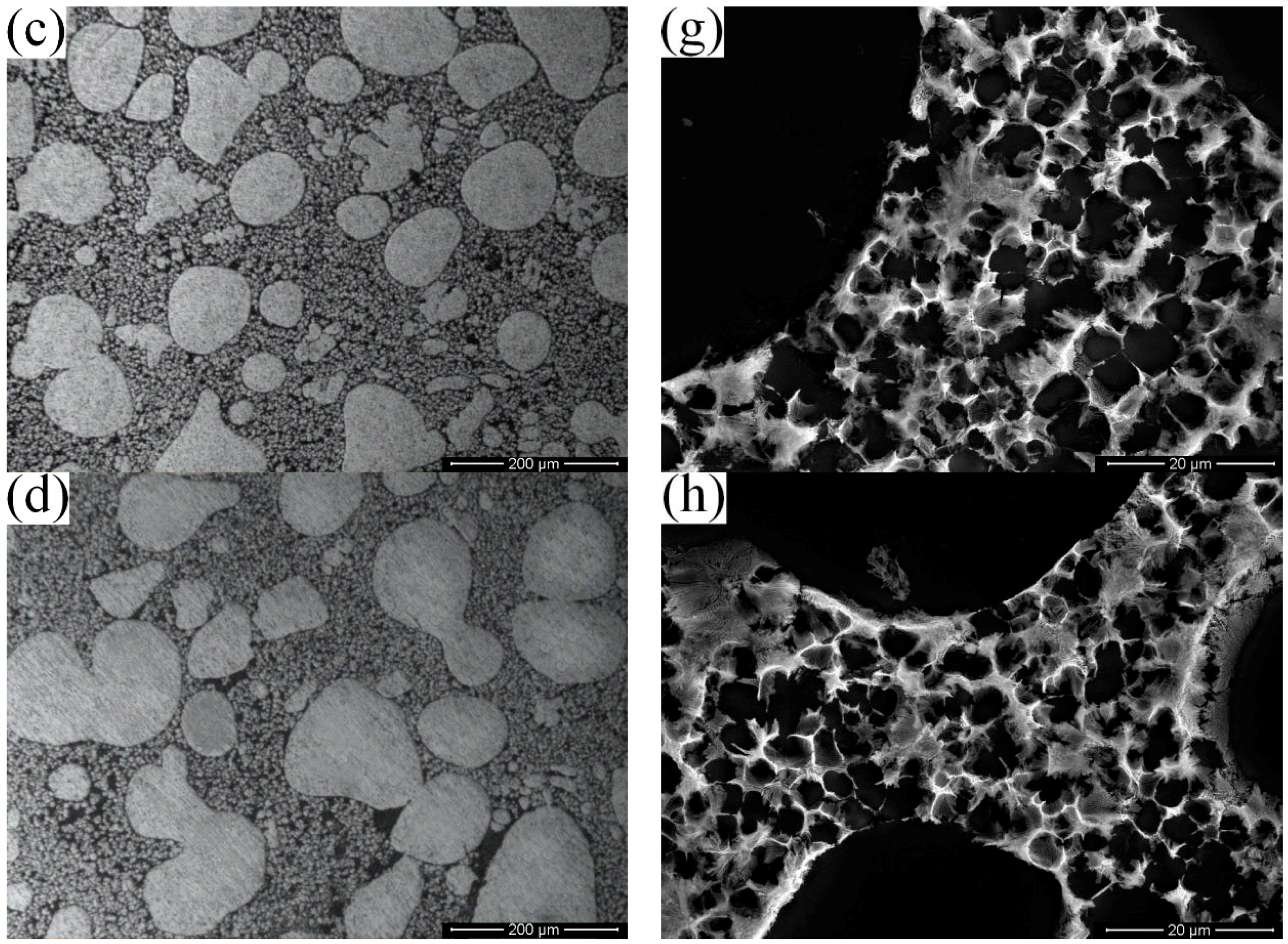
Figure 5.
Changes of the primary particle size and shape factor with the holding time (a) and the linear fitting curve (b).
Figure 5.
Changes of the primary particle size and shape factor with the holding time (a) and the linear fitting curve (b).
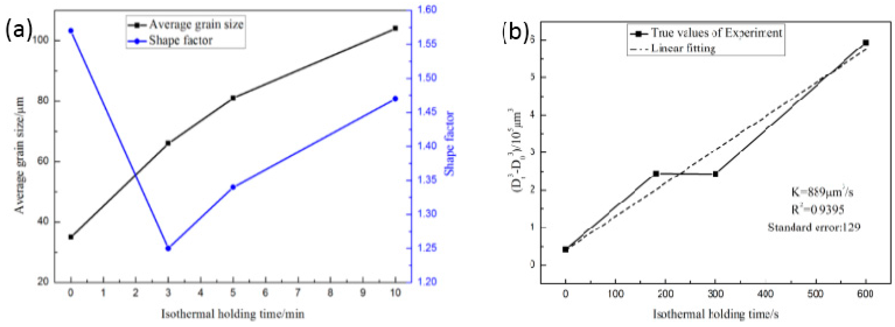
Figure 6.
The distribution of the secondary particle size in thin-walled die-casting (a) 0 min, (b) 3 min, (c) 5 min, (d) 10 min, and (e) the total distribution.
Figure 6.
The distribution of the secondary particle size in thin-walled die-casting (a) 0 min, (b) 3 min, (c) 5 min, (d) 10 min, and (e) the total distribution.

Figure 7.
Microstructures in different positions of die casting: (a,e) biscuit, A; (b,f) in-gate, B; (c,g) down, C; (d,h) middle, D.
Figure 7.
Microstructures in different positions of die casting: (a,e) biscuit, A; (b,f) in-gate, B; (c,g) down, C; (d,h) middle, D.

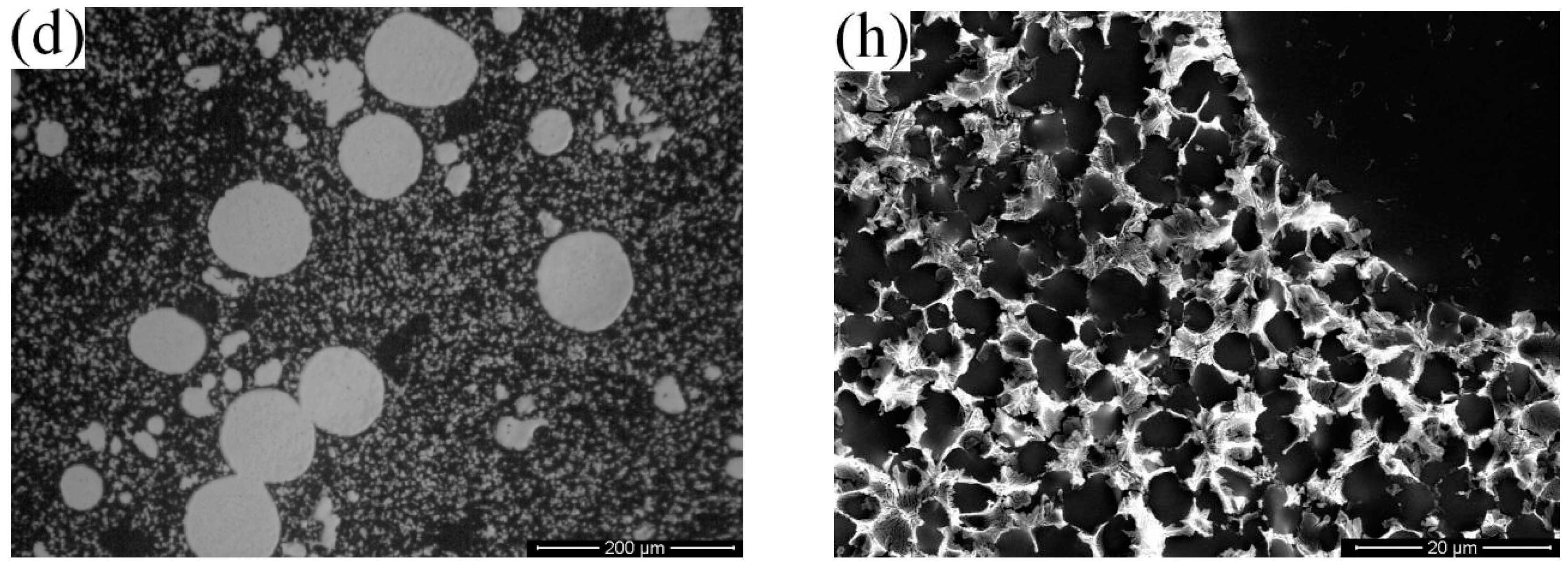
Figure 8.
The morphology of the eutectic phase (a) High Pressure Die Casting (HPDC); (b) Rheo-Diecasting (RDC).
Figure 8.
The morphology of the eutectic phase (a) High Pressure Die Casting (HPDC); (b) Rheo-Diecasting (RDC).

Figure 9.
Morphology of the eutectic structures in different positions of die casting (a) biscuit, A; (b) in-gate, B; (c) down, C; (d) middle, D.
Figure 9.
Morphology of the eutectic structures in different positions of die casting (a) biscuit, A; (b) in-gate, B; (c) down, C; (d) middle, D.

Figure 10.
Element distribution diagram of alloy A356 by RDC (a) stable growth interface of α1 particles, (b) instable growth interface of α1 particles: A “cellular” structure and B “dentation” structure.
Figure 10.
Element distribution diagram of alloy A356 by RDC (a) stable growth interface of α1 particles, (b) instable growth interface of α1 particles: A “cellular” structure and B “dentation” structure.

Figure 11.
Morphology of α2 particles (A) equiaxed crystals and (B) “8” or “shuttle” shaped particles.
Figure 11.
Morphology of α2 particles (A) equiaxed crystals and (B) “8” or “shuttle” shaped particles.

Figure 12.
Average shape factor for the different range of grain sizes.

Figure 13.
Content of Si in the primary particles and secondary particles in different positions.


Table 1.
Chemical composition of commercial A356 alloy (wt %).
| Si | Mg | Fe | Ti | Cu | Zn | Al |
|---|---|---|---|---|---|---|
| 7.06 | 0.27 | 0.115 | 0.097 | 0.001 | 0.01 | Balance |
Table 2.
Average particle size and shape factor of α1 and α2 in different positions of diecasting.
| Positions | Primary Particles (α1) | Secondary Particles (α2) | ||
|---|---|---|---|---|
| Average Particle Size/μm | Shape Factor | Average Particle Size/μm | Shape Factor | |
| A | 73.32 | 1.63 | 35.34 | 2.02 |
| B | 63.37 | 1.36 | 8.21 | 1.65 |
| C | 63.17 | 1.32 | 7.42 | 1.57 |
| D | 55.48 | 1.25 | 6.74 | 1.31 |
© 2017 by the authors. Licensee MDPI, Basel, Switzerland. This article is an open access article distributed under the terms and conditions of the Creative Commons Attribution (CC BY) license (http://creativecommons.org/licenses/by/4.0/).
Share and Cite
MDPI and ACS Style
Li, M.; Li, Y.; Huang, X.; Ma, Y.; Guan, R. Secondary Solidification Behavior of A356 Aluminum Alloy Prepared by the Self-Inoculation Method. Metals 2017, 7, 233. https://doi.org/10.3390/met7070233
AMA Style
Li M, Li Y, Huang X, Ma Y, Guan R. Secondary Solidification Behavior of A356 Aluminum Alloy Prepared by the Self-Inoculation Method. Metals. 2017; 7(7):233. https://doi.org/10.3390/met7070233
Chicago/Turabian StyleLi, Ming, Yuandong Li, Xiaofeng Huang, Ying Ma, and Renguo Guan. 2017. "Secondary Solidification Behavior of A356 Aluminum Alloy Prepared by the Self-Inoculation Method" Metals 7, no. 7: 233. https://doi.org/10.3390/met7070233
Note that from the first issue of 2016, this journal uses article numbers instead of page numbers. See further details here.