Dissolution of Grain Boundary Carbides by the Effect of Solution Annealing Heat Treatment and Aging Treatment on Heat-Resistant Cast Steel HK30


1
Department of Mechanical Engineering, ISEP-School of Engineering, Polytechnic of Porto, 4249-015 Porto, Portugal
2
School of Engineering, Jönköping University, SE-55111 Jönköping, Sweden
*
Author to whom correspondence should be addressed.
Metals 2017, 7(7), 251; https://doi.org/10.3390/met7070251
Submission received: 29 May 2017
/
Revised: 18 June 2017
/
Accepted: 26 June 2017
/
Published: 5 July 2017
Abstract
:Decreasing the weight of heavy-duty vehicles is an ongoing concern. However, the need to deal with high temperatures in components such as manifolds imposes, by itself, some restrictions regarding material selection, being further limited when other required properties (e.g., functional, manufacturing or cost requirements) are taken into account. Cast austenitic stainless steels may represent a good choice in this context but the existence of concentrated chromium carbides can generate undesirable results. A good combination of heat treatments can be applied to cast heat-resistant austenitic stainless steels, in an effort to achieve the dispersion of fine carbides, consequently improving their microstructure, mechanical properties and creep resistance. In this work, an austenitic stainless steel usually used in high temperature applications was characterized and subjected to solution annealing and aging heat treatments. The material analyzed was the austenitic cast stainless steel HK30 and the goals of the work were to evaluate the effects of solution annealing heat treatments on the dissolution of grain boundary chromium carbides and the effects of aging treatments on creep resistance. The results show that the elimination of grain boundary chromium carbides is possible by applying a solution annealing heat treatment. Additionally, the precipitation of fine dispersed carbides is obtained after the aging treatment with an increase of hardness and, consequently, an expected improvement of creep resistance. Thus, the novelty presented by this work consists of selecting the best heat treatment combination in order to promote dispersion of carbides, thus avoiding further crack nucleation phenomena when parts are cyclically subjected to load and unload; this work also found the most adequate mechanical properties and achieved corrosion resistance regarding the application in heavy-duty vehicle components subjected to mechanical and thermal fatigue. By discovering methods of improving the properties of cast materials, large savings can be made both in terms of production costs as well as in the overall weight of the components.
1. Introduction
The increasing demand in the automotive industry to reduce CO2 emissions is the driving force behind improving fuel economy and enhancing combustion efficiency in the heavy-duty vehicle industry [1]. This will result in a change in composition of the emitted exhaust gases and an even higher exhaust temperature, bringing higher demands for both corrosion resistance and heat-resistance materials used for exhaust components. Heat-resistant cast stainless steels have been developed to meet the increasing demands in several applications [2,3], including exhaust components.
Austenitic cast stainless steels are usually found in the most demanding conditions where ferritic alloys show limitations [2,3,4,5,6]. Besides chromium, they present high amounts of nickel in their composition to stabilize the austenite phase [7,8,9].
The heat-resistant cast stainless steel HK30 (ASTM A351) is a 25Cr/20Ni alloy commonly found in exhaust manifolds of high power gasoline engines, where the gas temperatures may reach 1000 °C [7,8,9]. The microstructure is composed of austenite with massive carbides embedded in the matrix. When the cooling rate is slow, precipitation of carbides at the grain boundaries may occur, depleting the matrix of chromium and making the steel more sensitive to intergranular corrosion. Furthermore, the ductility is reduced and the material becomes more brittle. This precipitation phenomenon occurs when materials are subjected to working conditions that present large thermal amplitudes, ranging from room temperature to elevated temperatures, and then are allowed to cool slowly enough to permit steel sensitization [10]. Welding processes may also lead to a similar outcome when slow cooling is also present.
The literature refers to the susceptibility of stainless steels to intergranular corrosion when chromium carbides precipitate at the grain boundaries, during high temperature exposure [10,11]. These chromium carbides, type M7C3 and M23C6 (M = Fe, Cr) [11,12], will deplete the surrounding matrix of chromium and make the alloy more sensitive to intergranular corrosion. This is easy to understand since these chromium carbides present a chromium content between 24% and 60% [13,14]. These carbide networks usually appear when the alloy is cooled very slowly through high temperature ranges, in which the carbon-rich austenite rejects the carbon (maximum carbon solubility of 2.06% at 1148 °C in the austenite) as grain boundary networks instead of dispersed particles [7,8,10].
Solution annealing heat treatment is usually applied in austenitic cast stainless steels to prevent alloy sensitization. The treatment consists of a holding time at high temperatures in the range of 1040 to 1205 °C in order to dissolve the carbides back to the matrix, followed by severe cooling to prevent carbides re-precipitation. This is possible due to the increase of carbon solubility in austenite—a consequence of the elevated temperatures. Another important consideration is that carbon carbides will always be present to some extent in the microstructure of alloys with carbon contents greater than 0.20%, such as HK30 alloy, regardless of the solution annealing treatment applied [15,16].
Usually, the solution annealing heat treatment is followed by an aging treatment in order to promote a fine dispersed precipitation of carbides, improving creep resistance [10,17]. Aging at 760 °C promotes the precipitation of fine, uniformly dispersed carbides resulting in a higher strength level and can be kept up to temperatures of around 980 °C, at which point secondary carbides start to agglomerate and spheroidize, decreasing the creep strength [10]. Another study [18] regarding 23-8-N nitronic steel, an austenitic stainless steel containing nitrogen in its matrix in order to improve its mechanical strength, toughness, ductility, erosion and corrosion resistance, showed that a solution treatment at 1220 °C for 150 min ensures the best carbide dissolution in the austenite phase, also showing a good combination of high toughness and elevated mechanical strength, improving significantly erosion resistance.
The purpose of this work is to study the possibility of eliminating the grain boundary carbides that may appear during material processing, by applying solution annealing heat treatments and the effects of aging treatments on the microstructure and hardness of the heat-resistant cast steel HK30.
2. Materials and Methods
2.1. Materials Characterization
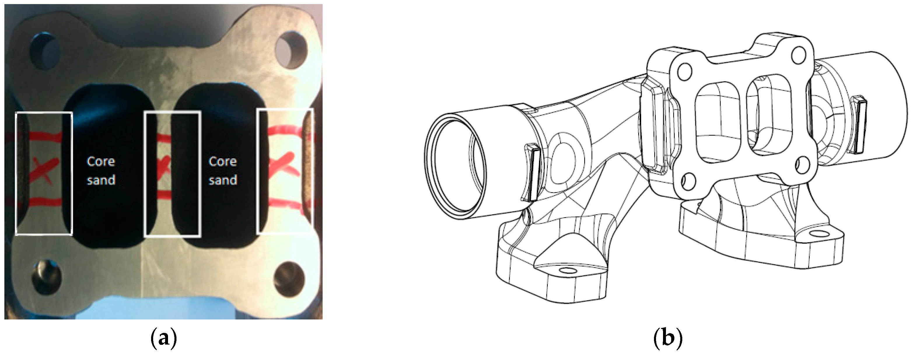
Cross-section samples were removed from several exhaust manifolds (seen in Figure 1) produced in an automated sand casting molding process using HK30 cast steel. Five samples were extracted regarding each heat treatment condition and considering three different areas, as depicted in Figure 1a, attending as well to different cooling conditions in the application considered in this work. The chemical composition of HK30 is given in Table 1. The samples presented a rectangular shape, 20 mm in length and around 6 mm in thickness.
Material characterization was conducted through microstructure analyzes and hardness measurements. All the samples were cut, mounted, polished and etched. The etch reagent used was Kallings Etsmedel etchant (LabService, Stockholm, Sweden) (5 g of copper chloride, 100 mL of hydrochloric acid, 100 mL of ethanol, 100 mL of water).
A CARL ZEISS AX10 (Carl Zeiss Microscopy, Jena, Germany) optical microscope with an incorporated AXIOCAM MRC digital camera (Carl Zeiss Microscopy, Jena, Germany) was used for microstructure observation. Micro and macro hardness measurements were performed with a Matsuzawa MxT30 (Matsuzawa, Akita, Japan) and a KB 3000 BVZ (ball diameter of 2.5 mm with a nominal test load of 187.5 kg, Hochdorf, Assenheim, Germany) testing machines, respectively. The results presented are the average of five measurements.
Some microstructural analyzes, carried out by a scanning electron microscope (SEM) and X-ray microanalyses (EDS) were performed using a FEG-SEM/EDS Zeiss Sigma VP (Carl Zeiss Microscopy, Jena, Germany) provided with a Gemini field emission column and element microanalysis (Carl Zeiss Microscopy, Jena, Germany) was carried out with an Energy Dispersive Spectrometer, EDS INCA Oxford Instruments (Oxford Instruments, Abingdon, UK).
2.2. Heat Treatments
A series of heat treatments was conducted, changing three variables: solution annealing holding time, quenching medium (after the solution treatment holding time) and the aging holding time. The heat treatment effectiveness was evaluated through microstructural analysis by optical and scanning electron microscopes and hardness measurements. Table 2 shows the chosen variables and range of respective values.
Table 3 shows the experimental matrix obtained after decomposing the variables.
Fixed temperatures were selected for solution annealing and aging heat treatments, 1200 and 760 °C, respectively. The solution heat treatment temperature (1200 °C) applied is almost the maximum temperature referred to by the literature [10] in order to ensure the effective dissolution of grain boundary carbides in the matrix. At 760 °C [10], the precipitation of fine, uniformly dispersed carbides is promoted, improving the creep resistance. The cooling applied after the aging holding time was still performed by air. Figure 2 shows schematically the different thermal cycles employed.
3. Results and Discussion
3.1. As-Cast Microstructure
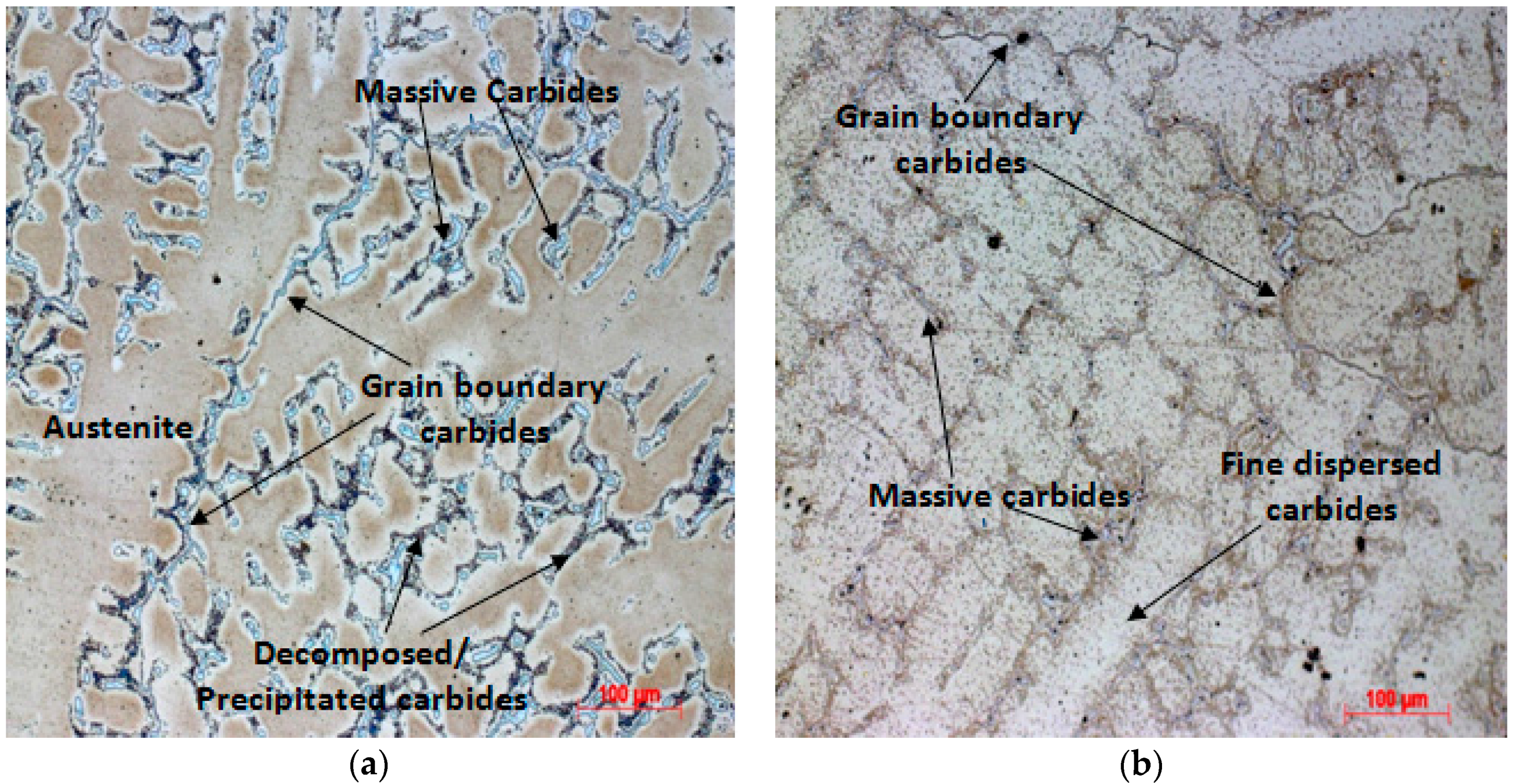
The HK30 is a 25Cr/20Ni alloy, so it is an iron-chromium-nickel alloy; a microstructure is expected that is composed of an austenitic matrix containing relatively large carbides in the form of either unconnected islands or as networks [10]. Figure 3a presents the as-cast microstructure of HK30 samples composed of a fully austenitic matrix and carbides, as individual islands and networks at grain boundaries. As can be seen in Figure 3b, there are unconnected carbide islands dispersed into each grain in the as-cast samples. As referred to previously, the carbide networks formed at the grain boundaries can promote material intergranular corrosion and embrittlement. For these reasons, heat treatments were designed in order to eliminate the carbide networks and consequently improve ductility, creep and corrosion resistance at high temperatures.
3.2. Solution Annealing Followed by Water Quenching
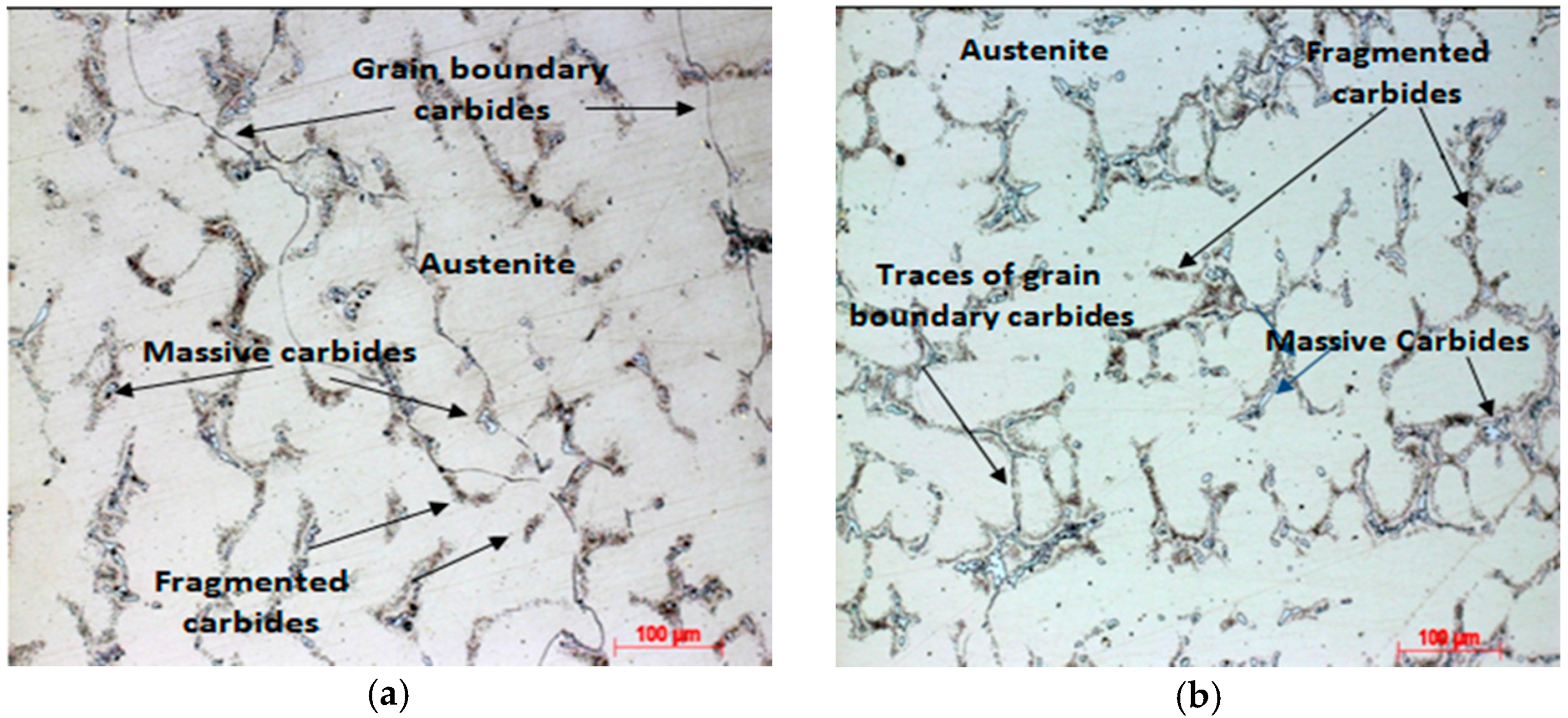
Figure 4 shows microstructures obtained from samples after solution annealing treatment. The quenching mean for both samples was water. Figure 4a represents the microstructure of a sample solution annealed at 1200 °C for 1.5 h. It is possible to distinguish some differences compared with the as-cast sample. When comparing Figure 3a with Figure 4a, a decrease in grain boundary carbides is clear. The carbides were partially dissolved back into the matrix, becoming thinner and disconnected. For the sample solution annealed at 1200 °C for 3 h (Figure 4b), there are far less grain boundary carbides compared with the sample solution annealed for 1.5 h, which was expected, since the dissolution of carbides is also a time dependent process. A sufficient amount of time is necessary to accomplish the maximum carbon dissolution in austenite [19]. From the X-ray microanalysis, the chromium content near carbides was higher (26.3%) than in the middle of the matrix (24.5%) for the sample ST/1.5 h. This can be explained by the dissolution of grain boundary carbides during solution annealing, increasing the chromium contents close to carbides.
For both samples in Figure 4, very small carbides are present near massive and grain boundary carbides. These small carbides or decomposed carbides may be the result of the dissolution of lamellar massive and grain boundary carbides during the solution annealing, since they are not visible in the as-cast state. The literature states that at high temperatures, such as those used in this experiment, carbides can be dissolved or spheroidized [19]. Increasing the solution annealing holding time, these massive carbides become bigger, possibly due to the agglomeration of decomposed carbides from previous massive carbides. A difference between massive carbide sizes is visible, being bigger in the sample solution annealed for 3 h (Figure 4b) than 1.5 h (Figure 4a).
From these experiments, we can conclude that during solution annealing heat treatment, carbide dissolution takes place until the maximum carbon solubility in austenite is reached. When the solubility limit of carbon is reached, carbide dissolution stops and carbide agglomeration starts, due to the high temperature [15].
3.3. Solution Annealing Followed by Oven Cooling
Microstructures obtained for sample solutions annealed at 1200 °C, followed by oven cooling, are presented in Figure 5, for 1.5 and 3 h holding time. When comparing sample solutions annealed for 1.5 h (Figure 4a and Figure 5a), larger massive carbides and thicker grain boundary carbides are visible in the oven cooled sample than in the water quenched sample. The sample solution annealed for 3 h followed by oven cooling presents a greater quantity of grain boundary carbides than when compared with the water quenched sample. The slow cooling in an oven (around 120 °C/h) may be sufficient to keep the samples at high temperatures long enough for the carbide agglomeration process to take place. Also, a higher carbide concentration in the microstructure (increase of the carbide/matrix ratio) is visible. This can also be explained by the slow cooling, which enables further carbide precipitation, due to the decreasing of carbon solubility in austenite with temperature.
The carbide precipitation (due to the carbon excess in the austenite) at high temperature ranges, takes place as grain boundary networks, instead of as dispersed particles in the matrix [19]. This carbide precipitation tendency in grain boundaries can be seen by the more continuous carbide networks presented when comparing with both water quenched samples (Figure 4). The conclusion drawn at the end of these trials is that slow cooling after solution annealing heat treatment promotes the agglomeration of carbides and precipitation at grain boundaries of previous massive carbides. So, the dissolution effect of carbides in austenite after solution annealing loses its effect, if further cooling is slow enough to admit carbide precipitation and agglomeration at high temperatures.
3.4. Aging Heat Treatment—Sample Solutions Annealed Followed by Water Quenching
The aging treatments were applied after solution annealing heat treatments, to compare the effect of the solution annealing in the aging treatment.
Figure 6 presents the samples’ microstructures after aging. Figure 6a represents the 1.5 h solution annealed sample and Figure 6b the 3 h solution annealed sample, both having been quenched in water and aged for 24 h at 760 °C.
The microstructures presented in Figure 6 show a big difference when compared with the samples that have been just solution annealed for both quenching media. Fine dispersed carbides in the matrix are visible as we can see at higher magnifications in Figure 6c,d. Carbon further from grain boundaries remains in supersaturated austenite, with longer holding times and greater supersaturation being needed for the nucleation and growth of these precipitates to occur [20]. Thus, the previous samples (without aging) did not remain at high temperatures long enough to admit precipitation of these fine dispersed carbides. The aged samples both present fine dispersed carbides in the austenite matrix. However, as referred to previously, for solution annealed and water quenched samples, the 1.5 h solution annealed sample presents disconnected thin grain boundary carbides, whereas the 3 h solution annealed sample shows no visible grain boundary carbides in Figure 6. As for solution annealed samples after water quenching, the higher the holding time the larger the massive carbides are.
3.5. Aging Heat Treatment—Sample Solutions Annealed Followed by Oven Cooling
The effect of samples oven cooled after the solution annealing on aging treatment was also evaluated.
From Figure 7, one thing is clear: the precipitation of fine dispersed carbides was much less intense when compared with the water quenched samples. Actually, the sample solution annealed for 1.5 h and aged does not present fine dispersed carbides in the matrix. The reason for the 3 h solution annealed sample presenting less fine dispersed carbide precipitation is, as mentioned before, the precipitation of carbon far from grain boundaries needs, besides a much longer period of time, greater supersaturation. During the slow cooling in the oven, precipitation of carbides takes place, depleting the matrix in carbon. When the aging treatment is applied, the austenite is less supersaturated in carbon, decreasing the possibility of precipitation of fine dispersed carbides far from the grain boundaries.
The lower the holding time at the solution annealed temperature, the less carbides are dissolved and consequently there will be less supersaturated austenite. Therefore, for the sample solution annealed for 1.5 h (Figure 7a), no fine dispersed carbides are visible in the matrix while for the sample with a higher holding time (3 h), some fine dispersed carbides are visible (Figure 7b).
3.6. Hardness Measurements
Figure 8 presents the macro-hardness obtained by each heat treatment. Figure 9 shows the micro-hardness measured on the matrix of each heat-treated sample. Note that the micro-hardness measurements for the cast stainless steel were conducted at three different areas of the samples’ surface, namely inside, in the middle and outside. These three places on the samples were analyzed in order to test the different cooling rates that may be subjected, despite the relatively low thickness of the samples (~6 mm). The inside surface represents the surface in contact with the core sand, the outside surface is in contact with the mould sand and the core of the sample is in the middle.
Returning to Figure 8, there is one main conclusion drawn from the results: sample ST/1.5 + W.Q. + AT clearly presents the highest hardness of all tested HK30 samples.
From Figure 9, it is visible that the highest hardness values are generally found on the outside surfaces when compared to the inside and middle surface measurements. This may be due to different cooling rates in each edge. The inside surface in contact with the core sand, and middle surface suffered lower cooling rates leading to lower hardness while the higher cooling rate of the outside surface resulted in higher hardness. The inside surface is in contact with the core sand which is surrounded by metal walls. During solidification, these metal walls release heat through the mould sand to the outside and to the core sand. The inside surface will have a slower decrease in temperature because the heat can only be released through the cast component’s metal walls, which consequently only occurs when there is a temperature decrease in the surrounding mould sand. For this reason, the inside surface during cooling remains at higher temperatures for a longer time than the outside surface.
For the as-cast HK30 sample in Figure 9, a higher error range in micro-hardness is visible at the outside surface, indicating some matrix heterogeneity. Actually, the highest error ranges were verified on the outside surfaces for the different heat treatments.
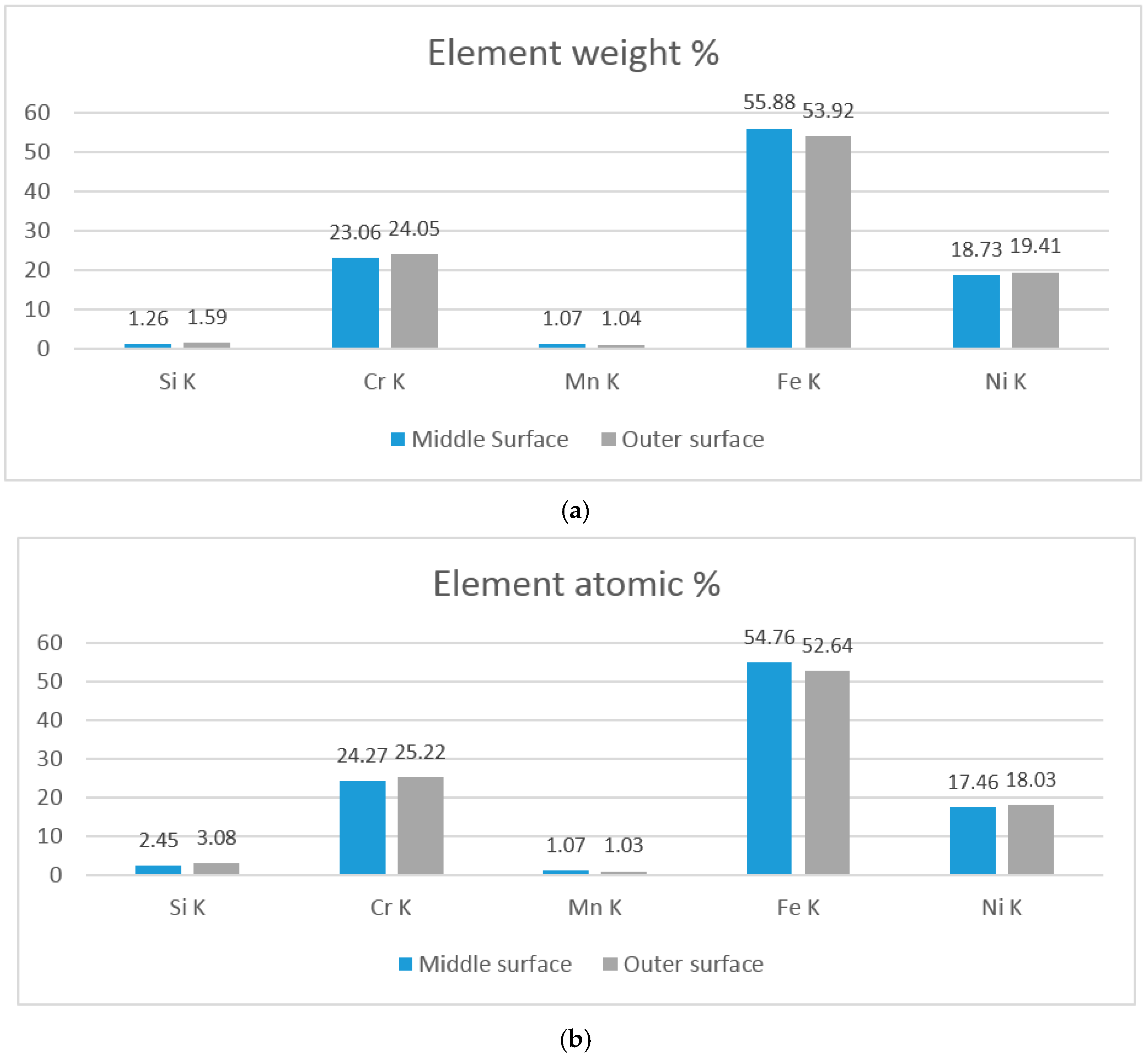
From X-ray microanalysis seen in Figure 10, the matrix presented less chromium content in the middle (23.0%) than on the outside surface (24.1%). This also shows that there may be less carbon content in the middle than on the inside surface.
The variation of hardness between the different zones is lower for the samples that have been solution annealed, which decreased the effect of having different cooling rates, experimented during the casting process. The increase of hardness was already expected before the trial, since applying a solution annealing heat treatment followed by aging heat treatment results in the highest creep resistance [10]. This is due to the fine dispersed carbide precipitation which consequently leads to the increasing hardness. Analyzing the microstructure and SEM micrographs, a dispersion of fine carbides on the matrix is visible, as expected. This precipitation may be the reason for the higher hardness in the 1.5 h solution annealed sample followed by water quenching and aged for 24 h.
Comparing the micro-hardness obtained for the middle section, this sample presents the highest hardness compared with all HK30 samples for the same zone. In real applications, the aging treatment does not need to be applied to promote the precipitation of fine dispersed carbides as, once in service, the component will achieve the temperatures needed to promote this precipitation.
The sample ST/3 + W.Q. + AT (Figure 9) presents lower average micro-hardness than the sample ST/1.5 + W.Q. + AT; the only difference between these samples is the length of the solution annealing time. Comparing the microstructures of both (Figure 6), the only visible difference is the presence of grain boundary carbides on the ST/1.5 + W.Q. + AT sample, which may not be the reason for this difference. Both samples present fine dispersed carbides in the matrix, although a longer stage at the solution annealed temperature may have resulted in the growth of austenite grain boundaries and consequently a decrease in hardness for the sample ST/3 + W.Q. + AT.
The samples ST/1.5 + O.C. + AT and ST/3 + O.C. + AT presented lower hardness compared with the sample ST/1.5 + W.Q. + AT. This can be explained by the slow cooling rate verified in the oven, causing precipitation and agglomeration of carbides at high temperatures during the slow cooling, reducing the carbon available in the matrix. Consequently, the carbon available for the formation of fine dispersed carbides (and to increase the hardness) during aging treatment is lower, thus less carbides will precipitate. From the microstructures in Figure 7, lower precipitation is visible compared with the samples quenched in water (Figure 6), in agreement with previous findings. Actually, the sample ST/1.5 + O.C. + AT does not present any fine dispersed carbides (Figure 7a), as previously mentioned. Despite the microstructure of the ST/1.5 + O.C. + AT sample not showing visible dispersion of fine carbides, higher hardness than the sample ST/1.5 + O.C. (Figure 8) is present. The cause of this difference may be fine precipitation that occurred during aging near the massive carbides, resulting in a darker zone of precipitates in Figure 7, when compared with Figure 5. This further precipitation may be responsible for the hardness increase.
Comparing both samples that were oven cooled and aged, we can conclude that the hardness is similar (Figure 8) due to the higher error range of the sample (ST/1.5 + O.C.).
4. Conclusions
Solution annealing and aging treatments were applied to the heat-resistant austenitic cast stainless steel HK30 and their effects were evaluated. The conclusions are the following:
- The formation of grain boundary carbides during alloy processing is possible. This can increase the risk of intergranular corrosion and crack initiation.
- The elimination of the grain boundary carbides can be achieved through the application of a solution annealing heat treatment.
- Aging treatment results in the precipitation of fine dispersed carbides and increase of hardness.
- Slow cooling at high temperature ranges promotes the precipitation of grain boundary carbides.
- The aging treatment will occur naturally in service at high temperatures.
Thus, the main novelty achieved in this work was to determine the best heat treatment combination and corresponding parameters in order to optimize the mechanical properties, fatigue resistance and corrosion behavior of the HK30 cast steel. With a proper combination of heat treatments, it is possible to achieve the best dispersing effect of grain boundary carbides, combining very good hardness values with an elevated toughness. Indeed, the first heat treatment steps can improve the hardness but allow for remaining concentrations of grain boundary carbides; these conditions allow crack nucleation when subjected to cyclic loads. The dispersion of carbides eliminates this concern, conferring very good global properties to the components, allowing HK30 cast steel’s application in heavy-duty vehicle components. For the example presented in this work (an exhaust manifold), the aging treatment will be carried out in service, allowing for additional cost savings.
Acknowledgments
This work was conducted at Scania CV AB in the scope of the Master’s Degree in Mechanical Engineering-Materials and Manufacturing Technologies at ISEP-School of Engineering, Polytechnic of Porto. The author is thankful to Scania for the thesis project opportunity. The author would like to acknowledge Mimmi Härdeman, Henrik Sieurin and Baohua Zhu from Scania for valuable support and discussions.
Author Contributions
Jorge Santos conceived and designed the experiments, as well as performed the experiments; Jorge Santos, Francisco J. G. Silva and Ronny Gouveia analyzed the data; Jorge Santos and Francisco J. G. Silva wrote the paper. Ronny Gouveia revised the manuscript.
Conflicts of Interest
The authors declare no conflict of interest.
References
- Schöggl, J.P.; Baumgartner, R.J.; Hofer, D. Improving sustainability performance in early phases of product design: A checklist for sustainable product development tested in the automotive industry. J. Clean. Prod. 2017, 3, 1602–1617. [Google Scholar] [CrossRef]
- Park, D.B.; Huh, M.Y.; Jung, W.S.; Suh, J.Y.; Shim, J.H.; Lee, S.C. Effect of vanadium addition on the creep resistance of 18Cr9Ni3CuNbN austenitic stainless heat resistant steel. J. Alloys Compd. 2013, 574, 532–538. [Google Scholar] [CrossRef]
- Koa, S.J.; Kim, Y.J. High temperature fatigue behaviors of a cast ferritic stainless steel. Mater. Sci. Eng. A 2012, 534, 7–12. [Google Scholar] [CrossRef]
- Kim, Y.J.; Jang, H.; Oh, Y.J. High temperature low cycle fatigue properties of a HF30-type cast austenitic stainless steel. Mater. Sci. Eng. A 2009, 526, 244–249. [Google Scholar] [CrossRef]
- Shi, S.; Lippold, J.C. Microstructure evolution during service exposure of two cast, heat-resisting stainless steels—HP-Nb modified and 20–32Nb. Mater. Charact. 2008, 59, 1029–1040. [Google Scholar] [CrossRef]
- Nunes, F.C.; Dille, J.; Delplancke, J.L.; De Almeida, L.H. Yttrium addition to heat-resistant cast stainless steel. Scr. Mater. 2006, 54, 1553–1556. [Google Scholar] [CrossRef]
- Ekström, M.; Jonsson, S. High-temperature mechanical- and fatigue properties of cast alloys intended for use in exhaust manifolds. Mater. Sci. Eng. A 2014, 616, 78–87. [Google Scholar] [CrossRef]
- Ekström, M. Development of a Ferritic Ductile Cast Iron for Increased Life in Exhaust Applications. Bachelor’s Thesis, KTH Industrial Engineering Management, Stockholm, Sweden, 7 May 2013. [Google Scholar]
- Li, D.; Sloss, C. Comment on High-temperature mechanical and fatigue properties of cast alloys intended for use in exhaust manifolds by Ekström et al. (Mater. Sci. Eng. A 616 (2014) 78). Mater. Sci. Eng. A 2015, 624, 90–91. [Google Scholar] [CrossRef]
- Davis, J. Heat-Resistant Materials; ASM International: Geauga County, OH, USA, 1997; pp. 247–322. ISBN 978-0-87170-596-9. [Google Scholar]
- Sustaita-Torres, I.A.; Haro-Rodríguez, S.; Guerrero-Mata, M.P.; Garza, M.; Valdés, E.; Deschaux-Beaumed, F.; Colás, R. Aging of a cast 35Cr–45Ni heat resistant alloy. Mater. Chem. Phys. 2012, 133, 1018–1023. [Google Scholar] [CrossRef]
- Laird, R.G. Abrasion-Resistant Cast Iron Handbook; ASM International: Geauga County, OH, USA, 2000; pp. 125–286. ISBN 978-0-87433-224-7. [Google Scholar]
- Santos, H. Aços Inoxidáveis Austeníticos; Lesson #14; Faculdade de Engenharia da Universidade do Porto: Porto, Portugal, 2007. (In Portuguese) [Google Scholar]
- Guimarães, A.A.; Mei, P.R. Precipitation of carbides and sigma phase in AISI type 446 stainless steel under working conditions. J. Mater. Process. Technol. 2004, 155–156, 1681–1689. [Google Scholar] [CrossRef]
- Sourmail, T. Precipitation in creep resistant austenitic stainless steels. Mater. Sci. Technol. 2001, 1, 1–14. [Google Scholar] [CrossRef]
- Ha, V.T.; Jung, W.S. Effects of heat treatment processes on microstructure and creep properties of a high nitrogen 15Cr–15Ni austenitic heat resistant stainless steel. Mater. Sci. Eng. A 2011, 528, 7115–7123. [Google Scholar] [CrossRef]
- Wang, J.Z.; Liu, Z.D.; Bao, H.S.; Cheng, S.C. Evolution of precipitates of S31042 heat-resistant steel during 700 °C aging. J. Iron Steel Res. Int. 2013, 20, 113–121. [Google Scholar] [CrossRef]
- Kumar, A.; Sharma, A.; Goel, S.K. Effect of heat-treatment on microstructure, mechanical properties and erosion resistance of cast 23-8-N nitronic steel. Mater. Sci. Eng. A 2015, 637, 56–62. [Google Scholar] [CrossRef]
- Davis, J.R. Stainless Steels; ASM International: Geauga County, OH, USA, 1994; pp. 459–474. ISBN 978-0-87170-503-7. [Google Scholar]
- McGuire, M.F. Stainless Steels for Design Engineers; ASM International: Geauga County, OH, USA, 2008; p. 77. ISBN 978-0-87170-717-8. [Google Scholar]
Figure 1.
HK30 cast stainless steel turbo manifold; (a) location of sample removal; (b) 3D CAD (Computer-aided design) drawing of turbo manifold.
Figure 1.
HK30 cast stainless steel turbo manifold; (a) location of sample removal; (b) 3D CAD (Computer-aided design) drawing of turbo manifold.

Figure 2.
Thermal cycles applied in heat treatments.
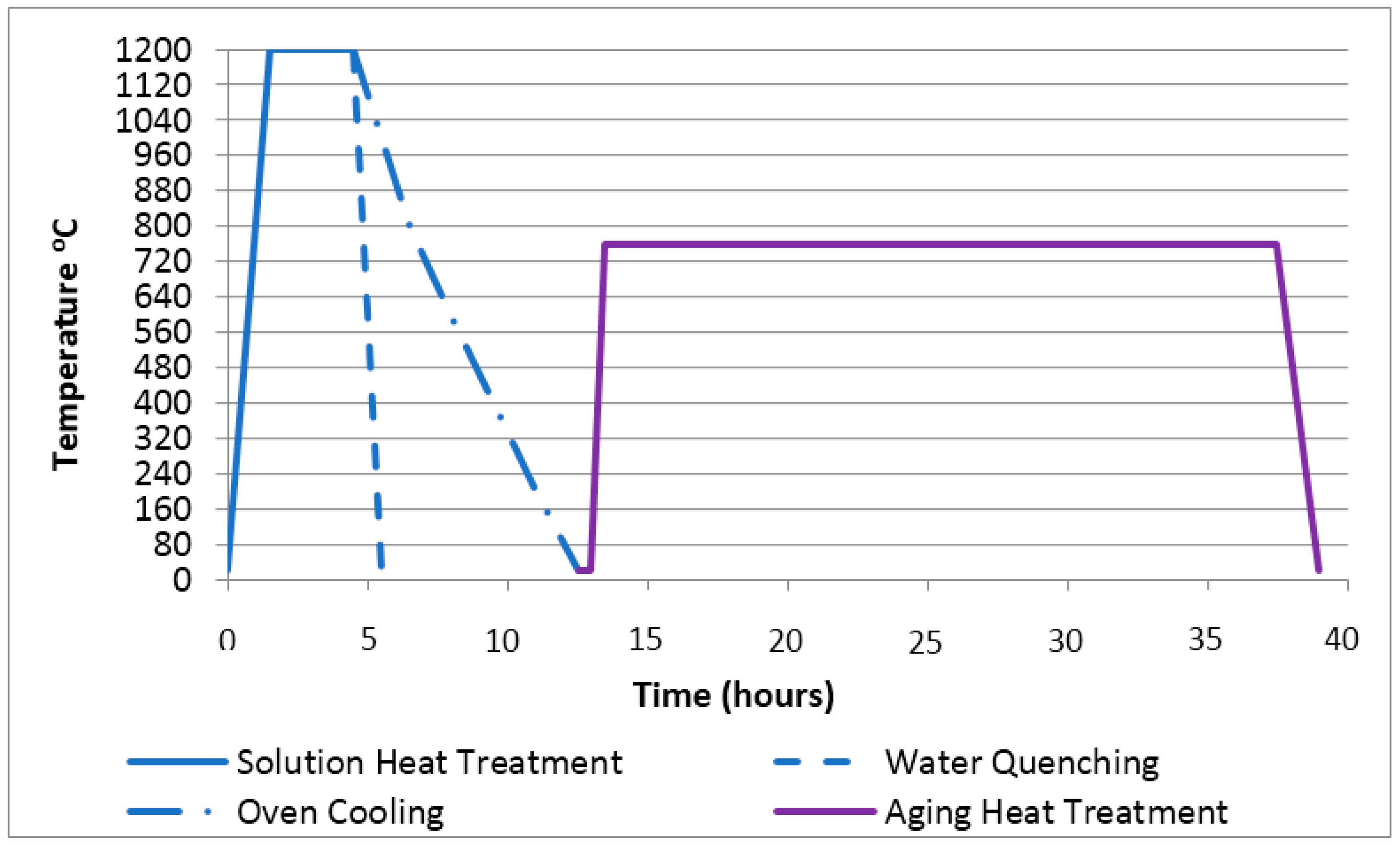
Figure 3.
(a) Microstructure obtained in as-cast state composed of a fully austenitic matrix, grain boundary chromium-rich carbides and massive carbides in the matrix; (b) SEM image of grain boundary carbides and unconnected carbide islands in the as-cast sample.
Figure 3.
(a) Microstructure obtained in as-cast state composed of a fully austenitic matrix, grain boundary chromium-rich carbides and massive carbides in the matrix; (b) SEM image of grain boundary carbides and unconnected carbide islands in the as-cast sample.
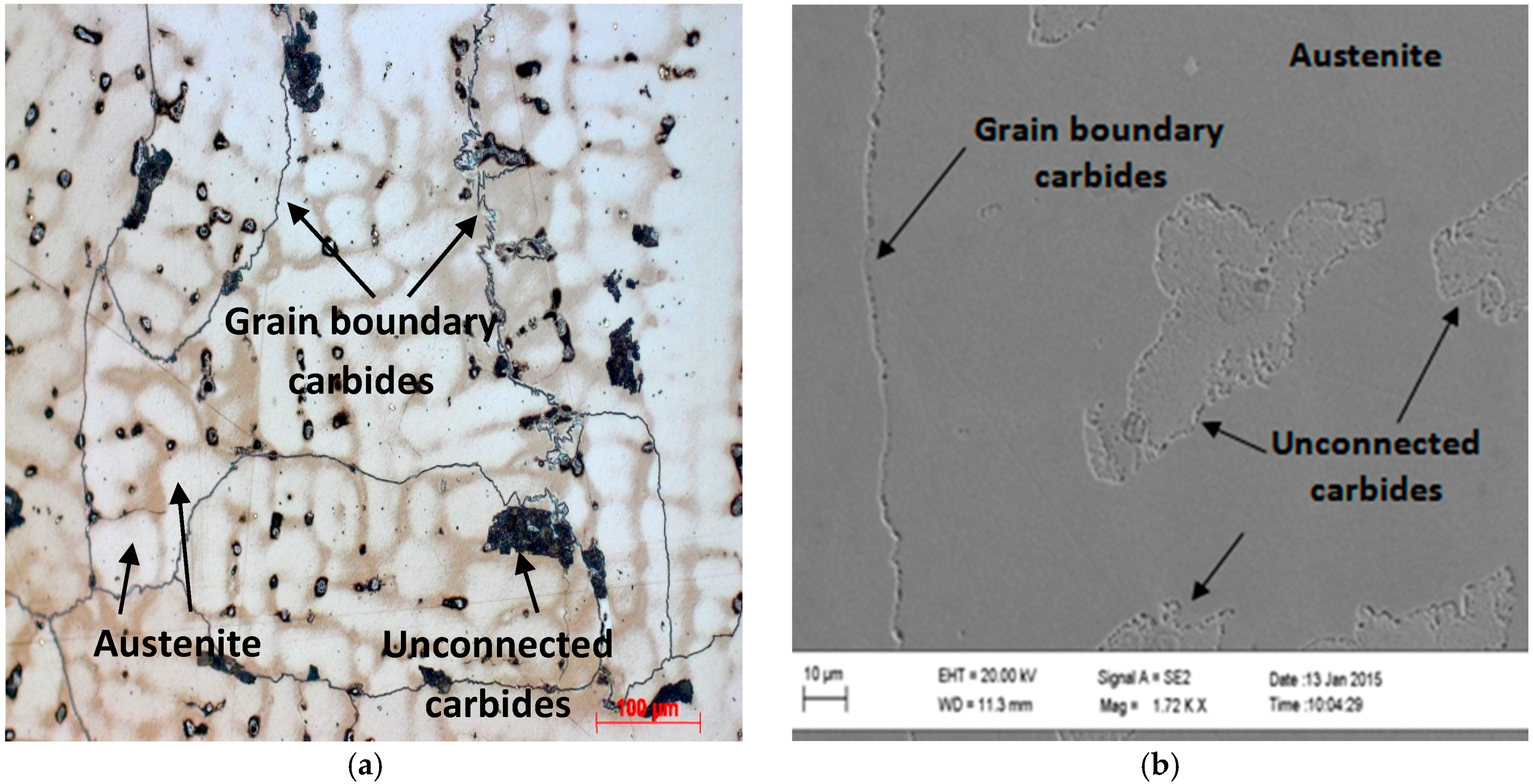
Figure 4.
(a) Microstructure obtained after solution annealing at 1200 °C for 1.5 h followed by water quenching; (b) Sample solution annealed at 1200 °C for 3 h followed by water quenching.
Figure 4.
(a) Microstructure obtained after solution annealing at 1200 °C for 1.5 h followed by water quenching; (b) Sample solution annealed at 1200 °C for 3 h followed by water quenching.

Figure 5.
(a) Microstructure obtained after solution annealing at 1200 °C for 1.5 h followed by oven cooling; (b) Sample solution annealed at 1200 °C for 3 h followed by oven cooling.
Figure 5.
(a) Microstructure obtained after solution annealing at 1200 °C for 1.5 h followed by oven cooling; (b) Sample solution annealed at 1200 °C for 3 h followed by oven cooling.
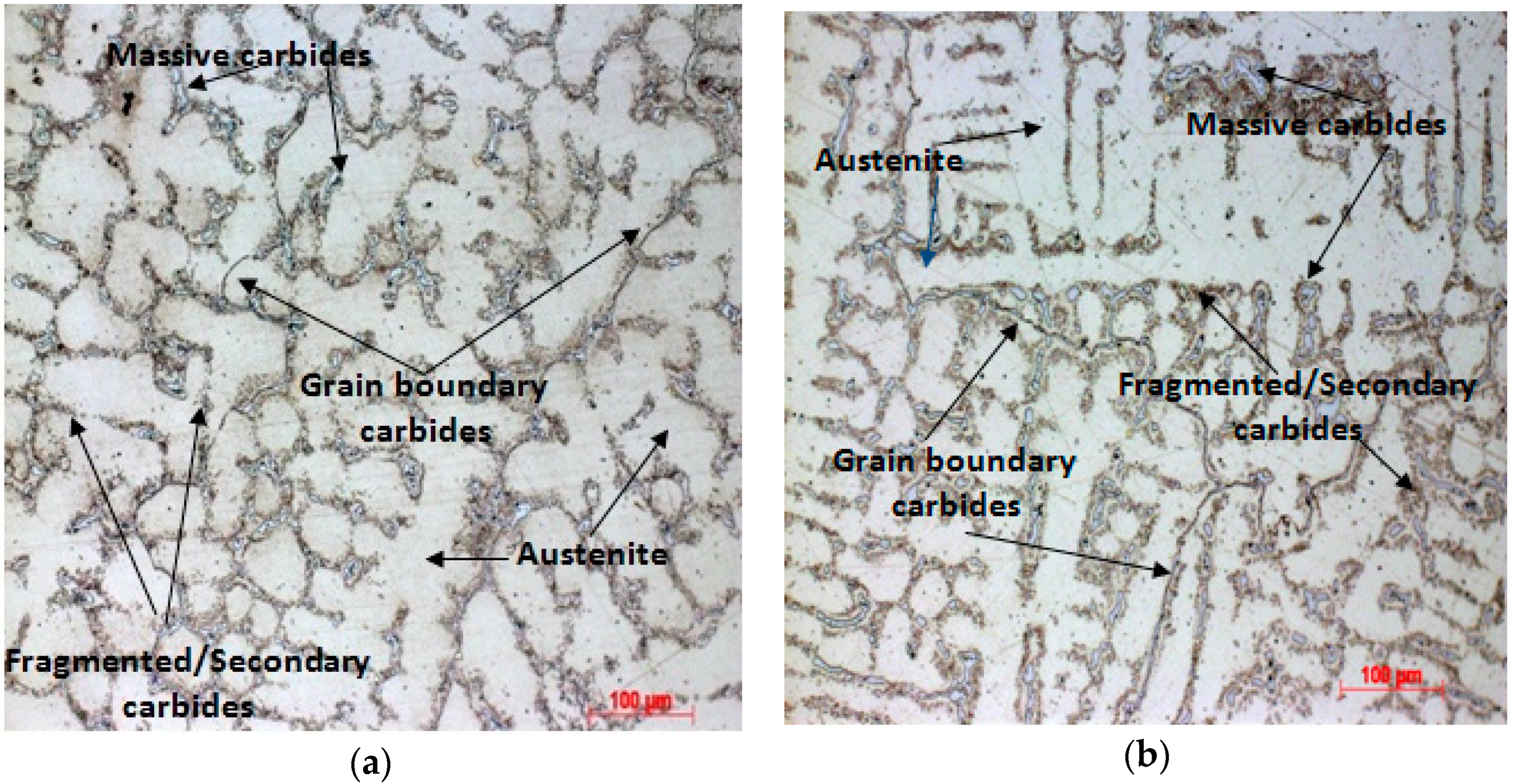
Figure 6.
(a) Microstructure obtained after solution annealing at 1200 °C for 1.5 h followed by water quenching and aged at 760 °C for 24 h; (b) Sample solution annealed at 1200 °C for 3 h followed by water quenching and aged at 760 °C for 24 h. (c) SEM micrograph for the sample solution annealed for 1.5 h followed by water quenching and aged for 24 h; (d) The same sample at higher magnification.
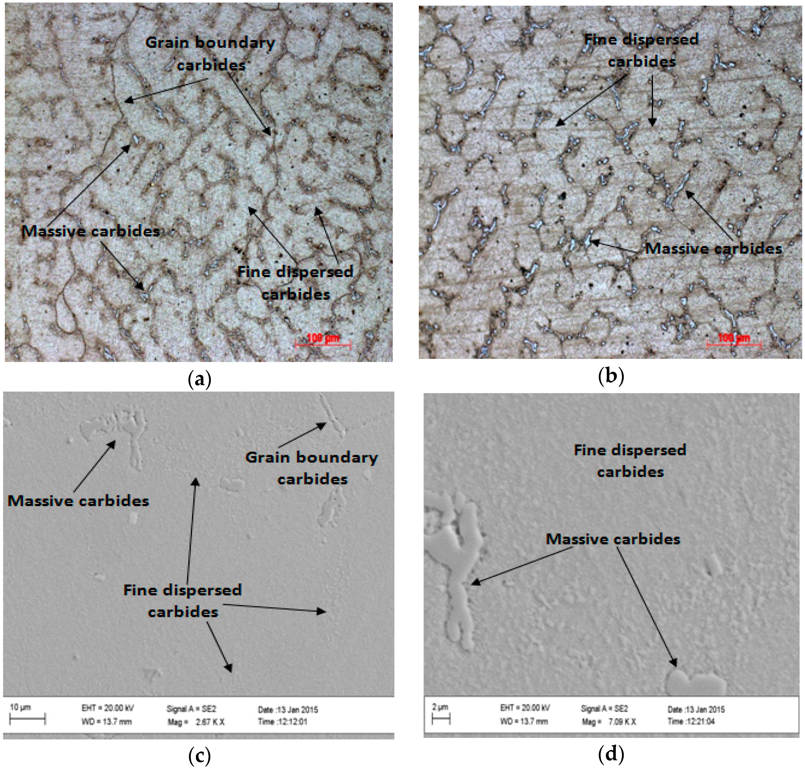
Figure 7.
(a) Microstructure obtained after solution annealing at 1200 °C for 1.5 h followed by oven cooling and aging; (b) Sample solution annealed at 1200 °C for 3 h followed by oven cooling.
Figure 7.
(a) Microstructure obtained after solution annealing at 1200 °C for 1.5 h followed by oven cooling and aging; (b) Sample solution annealed at 1200 °C for 3 h followed by oven cooling.

Figure 8.
Macro-hardness obtained for different heat treatments.
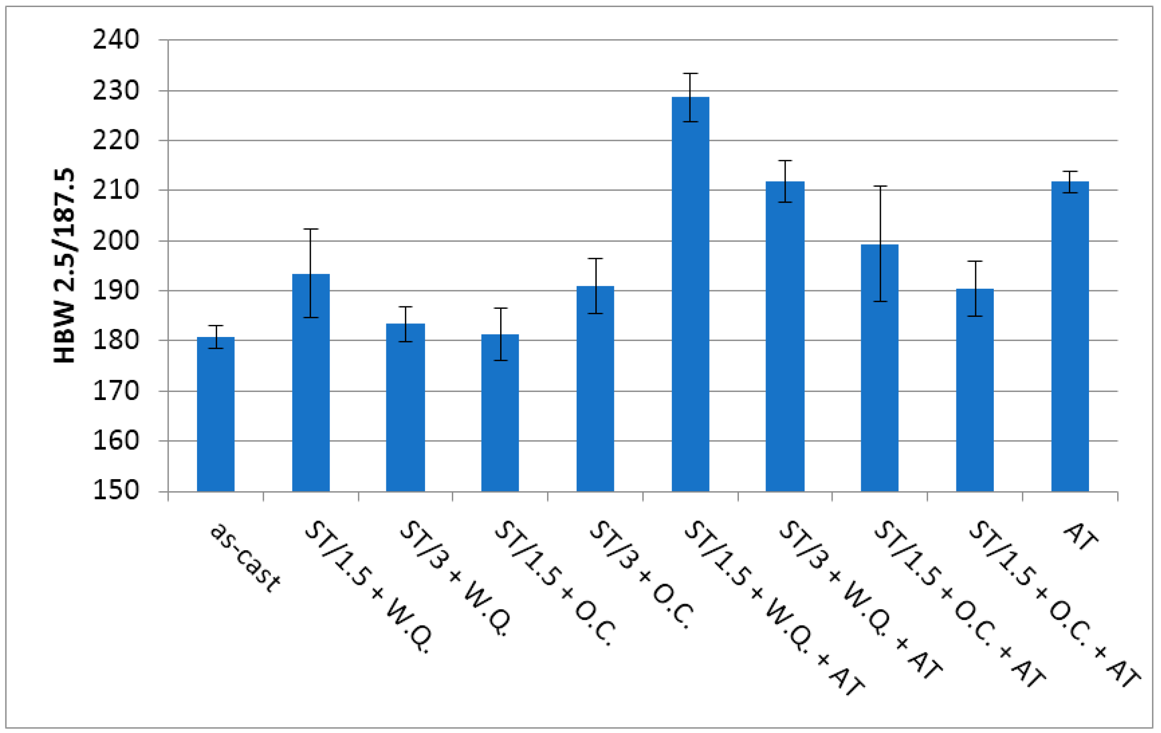
Figure 9.
Micro-hardness measured on the matrix obtained for each heat treatment.
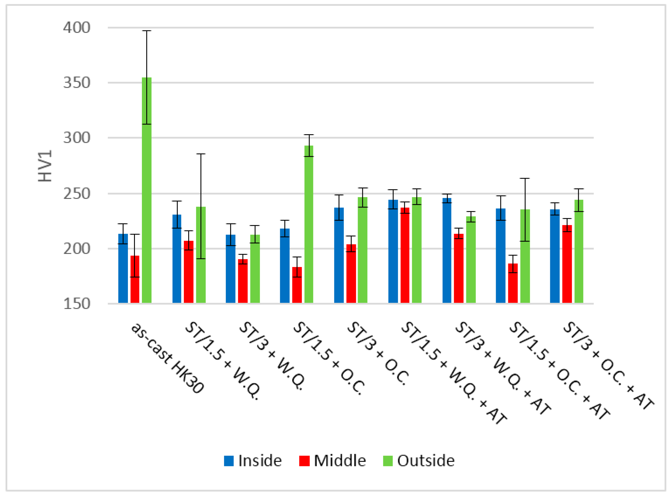
Figure 10.
(a) Element weight percentage results given by an X-ray microanalysis performed on the middle and outer surface of an as-cast sample; (b) Element atomic percentage results given by an X-ray microanalysis performed on the middle and outer surface of an as-cast sample.
Figure 10.
(a) Element weight percentage results given by an X-ray microanalysis performed on the middle and outer surface of an as-cast sample; (b) Element atomic percentage results given by an X-ray microanalysis performed on the middle and outer surface of an as-cast sample.


Table 1.
Chemical composition of austenitic stainless steel HK30 (wt %).
| Composition | Cr | Si | Mn | Cr | Ni | Mo | Cu |
|---|---|---|---|---|---|---|---|
| HK30 | 0.34 | 1.40 | 1.11 | 24.37 | 19.13 | 0.38 | 0.37 |
Table 2.
Variables and experimental parameters.
| Variables | − | + |
|---|---|---|
| ST—Solution annealing temperature holding time | 1.5 h | 3 h |
| QM—Quenching mean | Oven (O.C.) | Water (W.Q.) |
| AT—Aging holding time | 0 h | 24 h |
Table 3.
Matrix of experiments.
| Sample Designation | ST | QM | AT |
|---|---|---|---|
| ST/1.5 + O.C. | − | − | − |
| ST/3 + O.C. | + | − | − |
| ST/1.5 + W.Q. | − | + | − |
| ST/3 + W.Q. | + | + | − |
| ST/1.5 + O.C. + AT | − | − | + |
| ST/3 + O.C. + AT | + | − | + |
| ST/1.5 + W.Q. + AT | − | + | + |
| ST/3 + W.Q. + AT | + | + | + |
© 2017 by the authors. Licensee MDPI, Basel, Switzerland. This article is an open access article distributed under the terms and conditions of the Creative Commons Attribution (CC BY) license (http://creativecommons.org/licenses/by/4.0/).
Share and Cite
MDPI and ACS Style
Silva, F.J.G.; Santos, J.; Gouveia, R. Dissolution of Grain Boundary Carbides by the Effect of Solution Annealing Heat Treatment and Aging Treatment on Heat-Resistant Cast Steel HK30. Metals 2017, 7, 251. https://doi.org/10.3390/met7070251
AMA Style
Silva FJG, Santos J, Gouveia R. Dissolution of Grain Boundary Carbides by the Effect of Solution Annealing Heat Treatment and Aging Treatment on Heat-Resistant Cast Steel HK30. Metals. 2017; 7(7):251. https://doi.org/10.3390/met7070251
Chicago/Turabian StyleSilva, Francisco J. G., Jorge Santos, and Ronny Gouveia. 2017. "Dissolution of Grain Boundary Carbides by the Effect of Solution Annealing Heat Treatment and Aging Treatment on Heat-Resistant Cast Steel HK30" Metals 7, no. 7: 251. https://doi.org/10.3390/met7070251
Note that from the first issue of 2016, this journal uses article numbers instead of page numbers. See further details here.