Mg and Its Alloys for Biomedical Applications: Exploring Corrosion and Its Interplay with Mechanical Failure


Department of Mechanical and Industrial Engineering, Norwegian University of Science and Technology (NTNU Norway), 7491 Trondheim, Norway
*
Author to whom correspondence should be addressed.
Metals 2017, 7(7), 252; https://doi.org/10.3390/met7070252
Submission received: 6 June 2017
/
Revised: 25 June 2017
/
Accepted: 25 June 2017
/
Published: 5 July 2017
Abstract
:The future of biomaterial design will rely on temporary implant materials that degrade while tissues grow, releasing no toxic species during degradation and no residue after full regeneration of the targeted anatomic site. In this aspect, Mg and its alloys are receiving increasing attention because they allow both mechanical strength and biodegradability. Yet their use as biomedical implants is limited due to their poor corrosion resistance and the consequential mechanical integrity problems leading to corrosion assisted cracking. This review provides the reader with an overview of current biomaterials, their stringent mechanical and chemical requirements and the potential of Mg alloys to fulfil them. We provide insight into corrosion mechanisms of Mg and its alloys, the fundamentals and established models behind stress corrosion cracking and corrosion fatigue. We explain Mgs unique negative differential effect and approaches to describe it. Finally, we go into depth on corrosion improvements, reviewing literature on high purity Mg, on the effect of alloying elements and their tolerance levels, as well as research on surface treatments that allow to tune degradation kinetics. Bridging fundamentals aspects with current research activities in the field, this review intends to give a substantial overview for all interested readers; potential and current researchers and practitioners of the future not yet familiar with this promising material.
1. Introduction
In the last decades, concurrent with the increased lifetime in today’s world population, the amount of people undergoing surgical procedures involving the implantation of medical devices is continuously growing [1]. These implants are generally used for applications that ensure a substantial improvement in patients’ quality of life, such as orthopaedics, pacemakers, cardiovascular stents, defibrillators, neural prosthetics and drug delivery systems [2,3,4,5]. Among these, orthopaedic surgery is the most important [4], characterized by the highest annual growth rate. Indeed, according to Long and Rach [6], almost 90% of the population over 40 years is affected by degenerative joint diseases. Total hip replacements are predicted to represent half of the estimated total number of operations in 2030 [7]. For this reason, the research has centred on new biocompatible materials and on improving their performances [8,9,10]. Especially strength and corrosion resistance in human body fluid (HBF) has been a major issue of research [11].
Tailoring biomaterials to their specific use, many important properties must be considered. First, they must be bioinert or bioactive [12]; the former means that the organism has a coexistence with the material without noticeable change in the organism and/or exogenous material, whereas the latter implies that there is an interaction with and/or a response from living tissue, e.g., the formation of direct biochemical bonds with the surface of the material in bioceramics. Further, they must not evoke a sustained inflammatory response once implanted in the human body, have appropriate mechanical properties for their use and include appropriate permeability and processability for designed applications [13].
Several materials provide these properties and they can be divided into four main classes [4,14]: metals [15], polymers [16,17], ceramics [12,18] and composite materials [14,19]. It is worth to note that implant design, and therefore material choice, depends on the application of the devices and on the environment in which they are employed (Table 1).
Despite the recent technological evolution of polymeric and ceramic materials, metals, such as stainless steel, cobalt-chromium , and titanium alloys, are still the most used materials in biomedical applications, covering 70% of the total production volume [15,22,23].
What makes these materials irreplaceable are their high:
- (1)
- Strength
- (2)
- Fracture toughness
- (3)
- Ductility
- (4)
- Fatigue life
- (5)
- Wear resistance and
- (6)
- Corrosion resistance
It is widely reported [14,24] that bones are subjected to a stress of about 4 MPa on a daily basis and hip joints may experience a load as high as 10 times of the body weight in some cases, these implantable devices require high properties in terms of (1) and (2). Moreover, a high percentage of elongation at fracture (3) is needed in order to prevent brittle failure leading to the predominant choice of metallic implants as bioimplant materials. The human body also experiences dynamic loads: Ramakrishna et al. [14] reported that hip joints are subjected to loads applied for 1 × 10⁶ cycles per year making (4) a requirement. This kind of joints are also affected by sliding issues potentially leading to the formation of wear debris if (5) is not high enough. This again causes acute immune response resulting in inflammation and/or fibrosis [4]. Finally, implanting materials in the human body necessitates great biocompatibility implying that they do not release any toxic substances into the body (6).
However, since the mechanical properties of metals highly differ from those of human bone, they are not always suitable for medical devices (see Table 2): the bigger the difference in elastic modulus, the higher the occurrence of stress-shielding, which is a phenomenological consequence of stress distribution changes [25,26,27,28,29,30,31,32,33]. Bones adapt to the changed stress field according to the Wolff’s law [34], resulting in the bone either becoming more porous (internal remodelling) or thinner (external remodelling), leading to a higher risk of implant failure. Considering a hip joint, for example, upon the implantation of a respective prosthesis, the entire bone-biomaterial system can be abstracted as two springs in parallel (Figure 1).
The load redistribution phenomenon is strictly related to the stiffness ratio according to:
where σ and E is applied stress and material stiffness, respectively. Subscripts 1 and 2 refer to implant and bone, respectively. As the load on the bone decreases with the implant, the bone will become less dense and thinner due to the insufficient stimuli for continued remodelling (Figure 2).
Stress induced bone remodelling is widely described in literature [31,32,37] and several models have been proposed to explain this phenomenon. Van Rietbergen et al. [33] stated that the bone mass is regulated by the remodelling signal S, which is the strain energy (U) per unit of mass:
where ρ is the bone density. Bone remodelling as described in Equation (3) corresponds to the rate of net bone-mass turnover and happens when S differs from the characteristic reference value Sref describing the remodelling signal in non-operated conditions:
The theory further assumes that no remodeling takes place when S − Sref does not exceed a threshold. Huiskes et al. [38] agreed that local strain perturbation governs the remodelling process by means of an interaction with osteocytes, since they are widely reported to be transductor of mechanical signals [39,40,41,42]. They suggested that increased (or decreased) strain signals the osteocyte to transmit stimuli to the bone surface, where bone is formed (or removed) until the strain normalizes.
In certain biomedical applications, especially fixators such as bone plates, screws, pins and stents, biomedical devices are required to stay inside the human body only for a restricted period, i.e., as long as bones heal. Thus, materials that ideally degrade in the same manner and speed as natural bone heals [10,47,48] are widely required to be utilized for these temporary devices. Biodegradable materials allow circumventing cumbersome second surgeries involving the removal of the old implant. Besides complications and distress for the patient, this also increases insurance costs [49,50,51,52,53,54,55]. However, classic metallic materials as those above are not biodegradable and, if not removed, lead to long-term complications, as local inflammations due to the potential release of cytotoxic ions as a consequence of corrosion or wear processes [22,23,56,57,58]. It is therefore very attractive to identify materials that degrade in the same way as bone heals, dissolving entirely after complete healing. In this process, these materials must not cause any toxic, allergic, inflammatory or cancerous effects.
In recent years, researchers and clinicians have employed a variety of compositions, properties and forms in which polymers are available to best match the specifications of the materials’ desired biomedical function [4,13,16,20,59]. However, they tend to be too flexible and too weak for load-bearing applications required in orthopaedic surgery. Moreover, they may also absorb liquids and swell, leach undesirable products such as monomers, fillers and antioxidants, and, furthermore, the sterilization process may affect their properties [14].
Thus, to overcome this drawback of polymeric materials, researchers’ and clinicians’ attention focused on metallic biodegradable materials. Several of them have been studied but most of the scientific efforts focus on Magnesium (Mg) and its alloys. Among metallic engineering materials, Mg possesses one of the best bio-compatibilities with human physiology and the best mechanical compatibility with human bone [60]. Its low density and elastic modulus best mimic the properties of natural bones (Table 2). Moreover, Mg is the fourth most abundant element in the human body (it is recommended that an adult receives 240–420 mg daily) and it is essential for the metabolism in many biological mechanisms (Mg is a cofactor for many enzymes [46]). Finally, Mg2+ ions, resulting from the degradation process (see Section 2), are reported to aid the healing and growth of tissue. Any excess of these ions is harmlessly excreted in the urine [43].
Despite the advantageous properties of bioactive Mg and its alloys, there are some limitations for their use in temporary implants. The major drawback is the high corrosion rate in the physiological environment that may lead to a loss of mechanical integrity before tissues have sufficient time to heal. Moreover, hydrogen as a corrosion product together with the generation of respective hydrogen pockets can influence the healing process or, if the pockets are large, they may cause death of patients through blocking of the blood stream. Finally, the simultaneous action of the corrosive human-body-fluid and the mechanical loading can cause the further complication of sudden fracture of implants due to corrosion-assisted cracking, such as stress corrosion cracking (SCC) and corrosion fatigue (CF) [61,62,63].
The aim of this work is to describe the state of the art regarding corrosion behaviour assessment and the developed methods for improving the corrosion resistance of Mg. First a short summary of the degradation mechanism of magnesium in human body fluid will be provided, and then a focus on the corrosion-assisted cracking phenomena (SCC and CF). Finally, an overview of how to improve corrosion properties will be given.
2. Corrosion
The main drawback in the use of magnesium in orthopaedic implants is its high corrosion rate in the electrolytic physiological environment. Mg and its alloys are reactive metals and they corrode in aqueous environments according to the reactions given below [64,65]:
Mg + 2H2O → Mg(OH)2 + H2,
The corrosion reaction can be divided into the anodic and cathodic partial reaction, (5) and (6), respectively [66]:
Mg → Mg2+ + 2e−,
2H2O + 2e− → H2 + 2(OH−),
According to Equation (4), a film of Mg(OH)2 forms on the surface of Mg and its alloys, preventing further corrosion in water since it is slightly soluble there.
Mg2+ + 2(OH−) → Mg(OH)2,
However, if the corrosive medium contains any chlorides with concentration above 30 mmol/L [67], the magnesium hydroxide will be converted to magnesium chloride MgCl2 according to [43]:
Mg(OH)2 + 2Cl− → MgCl2 + 2(OH−)
Magnesium chloride is highly soluble in aqueous solution, determining the further corrosion development of Mg and its alloys in the human body, where the chloride content is about 150 mmol/L [68,69,70,71].
It is worth to note that the chemistry involved in the corrosion, i.e., magnesium chloride solubility and hydrogen evolution, highly influences the in vivo performances of magnesium devices. Starting from the solubility of MgCl2 film, it is reported that it can affect the mechanical behaviour in two different ways. According to Ghali et al. [72], two different corrosion modes are possible, uniform and localized. Mg alloys with slow and constant degradation rate (lower than 0.5 mm/year [65]) are required to facilitate sufficient time to heal for the bone. Further, a uniform degradation mode is key as localized corrosion can lead to toxicity and early failure of the implant. However, uniform corrosion is not the main corrosion mode. Kirkland et al. [73] reported that 29 of 31 Mg alloys suffer of localized corrosion, i.e., pitting. The difference discriminating uniform from localized corrosion is mainly linked to the presence of second phases, precipitates or impurities on the surface of the Mg alloys, inhomogeneities generally widely present in Mg and its alloys. The most common impurities are Fe, Ni and Cu. They are most harmful in terms of corrosion resistance due to their very negative corrosion potential [65,74,75,76]. They are cathodic with respect to the Mg matrix, resulting in a faster corrosion rate and determining a higher and more severe susceptibility to pitting that quickly destroys the Mg(OH)2 protective film [60]. Once this film is removed, the surrounding corrosive fluid will have contact with the Mg matrix, causing further corrosion according to the just mentioned mechanism. If the inhomogeneities are not uniformly distributed [65] or above a tolerance limit [77], the material will corrode in a localized manner, acting as precursor for stress corrosion cracking (SCC) and corrosion fatigue (CF). These mechanisms highly affect the corrosion resistance of Mg and its alloys, hampering their application for biomedical implants and they will be described in detail in the next section.
Hydrogen evolution due to the corrosion mechanism involved in Equation (4) influences the in vivo performances of Mg alloys in two ways [22,78,79,80,81,82]. First, when the corrosion rate is too high, human body cannot absorb the entire amount of developed hydrogen, thus generating gas pockets and bubbles. Though Witte et al. [70] found 0.068 mL/cm2/day leading to no subcutaneous bubbles after 2–3 weeks on guinea pig, and even if Song [79] set 0.01 mL/cm2/day as tolerated value in his work, no scientific evidence has been reported that these values can be used as a threshold for acceptable hydrogen amounts in the human body. In orthopaedic applications, where blood transport mechanisms are poor, these gas pockets are harmful since they occur around the device, causing risk of implant failure, tissue separation or, in the worst case, death of the patient due to blood clotting [79,80,81,82]. Second, hydrogen evolution is strictly connected to the corrosion-assisted cracking, i.e., SCC and CF, since their propagation is highly influenced by the hydrogen embrittlement (HE) phenomenon [22,78], which will be discussed in the next section.
3. Corrosion Assisted Cracking Phenomena
From the middle of the 20th century, several metallic materials have been reported susceptible to the synergistic effect of mechanical loads and corrosive medium, leading to corrosion assisted cracking phenomena, i.e., SCC and CF [61,62,63]. These mechanisms result from a simultaneous combination of three factors, susceptible material, corrosive environment and tensile stress. Mg and its alloys have gained interest as materials for biomedical devices due to their degradation properties upon exposure to the human body fluid, and hence researchers and clinicians have started to investigate the susceptibility of these materials to corrosion assisted cracking mechanisms. This involves the consideration of whether the mechanical property reduction results from the combination of applied stresses and corrosive environment, i.e., SCC, or simply is a consequence of the reduction of implant cross-section because of corrosion mechanisms. Choudhary and Raman [83] performed slow strain rate tensile (SSRT) tests on AZ91D alloy in modified simulated body fluid (m-SBF) at different conditions: (a) strained in air; (b) strained in m-SBF; (c) strained in air after a pre-immersion in m-SBF solution for a time as long as the time to failure of case (a); (d) continuously cathodically charged and simultaneously pulled in m-SBF. Comparing the results (Figure 3), they found a considerable reduction in mechanical properties of specimens stressed in m-SBF, leading to the conclusion that the synergistic effect of corrosive environment and mechanical loads, rather than the corrosive environment itself, mostly affects the corrosion resistance of Mg and its alloys.
Since orthopaedic devices are subjected to different acute loadings during their use, i.e., tension, compression, bending and torsion depending on human activities and skeletal location [78] and since these loadings are repetitive (just thinking to the daily activities of walking), SCC and CF are of great concern for the use of Mg and its alloys as material for biomedical devices. Moreover, Mg and its alloys suffer pitting in human body fluid, due to the presence of chlorides and impurities [43,60,67,68,77,78,84,85,86,87,88], making these phenomena main limitations. Chemical induced pits and implants’ sharp contours provide the required stress concentration for the onset of such phenomena, which are described below [60,89]. Their most detrimental effect is implant failure at stresses considerably below the yield and design stresses [83], i.e., at mechanical conditions otherwise considered to be safe [75]. Such sudden failure produces serious issues to the patient, such as the need of a complicated and harmful removal of the failed implant and subsequential inflammatory responses, as well as the necessity of a new device implantation.
This section provides the reader with a description of these phenomena. It should be noted that the mechanistic understanding of SCC and CF mostly derives from knowledge obtained on Mg-Al alloys. As Al is toxic to the human body, the mechanisms might not be entirely representative of biocompatible alloys, but it still provides a meaningful framework to describe the theory (see Section 5.2.1).
3.1. Stress Corrosion Cracking (SCC)
When static tensile stresses and corrosive environments act together on susceptible materials, they lead to the SCC. This mechanism is characterized by the onset and propagation of cracks, resulting in the embrittlement of ductile Mg in the corrosive medium leading to a considerable elongation reduction [60,83].
The onset of SCC requires a localized corrosion site, where the conditions for crack initiation are met. It is widely reported that these cracks initiate at high stress locations, such as roots of a corrosion pit or pre-existing microscopic flaws (surfaces defects) [60,75,78,83,90]. Localized corrosion sites take place after the fracture of the magnesium hydroxide protective film as a consequence of the chemical reaction with chloride ions according to Equation (8). This proceeds locally because second phases and/or impurities of the alloy underneath affect the protective film resistance. Moreover, it is widely reported [76] that the breakdown of the protective film also follows the applied stresses. Failure can derive from stress enhancing elements such as inclusions or notches in the implant geometries enhancing stresses from daily activities or residual ones introduced during device fabrication. Moreover, the presence of dynamic loading, i.e., CF, may lead to the formation of fatigue cracking providing a preferential site for SCC [60,75,91].
Once localized corrosion takes place, the cracks propagate until failure. However, the propagation phase is not well understood and literature distinguishes between several mechanisms. In their review, Winzer et al. [75] divided them into two groups of mechanisms:
- Anodic dissolution mechanisms categorized in the: (a) galvanic attack by film rupture model; (b) tunnelling model; (c) preferential attack model.
- Mechanical fracture mechanisms or cleavage-like fracture as described in the hydrogen embrittlement model.
The development of 1a started from the observation that SCC propagation in AZ31 alloys is halted once a cathodic current is applied. Logan [92,93] proposed an electrochemical model for the crack propagation phase under corrosive media. He theorized that once an applied strain is sufficient to produce a breakdown of the Mg(OH)2 protective film, an electrochemical cell occurs between the anodic film-free surface and the cathodic protective layer (Figure 4).
Moreover, he suggested that this electrochemical cell determines a localized corrosion that, acting as a notch, leads to a region of stress concentration. Thus the protective film does not reform, allowing a continuous crack propagation. However, some authors refuted this model for different reasons. Ebtehaj et al. [94] as well as Wearmouth et al. [95], for example, found a discontinuous crack growth taking place by an alternating sequence of film rupture and repassivation. A continuous propagation mode is possible only when repassivation is limited. Logan proposed this electrochemical model since he observed an improvement of corrosion resistance applying a cathodic current. However, he neglected that also hydrogen embrittlement models (which will be described later in this section) require a film-free surface that can be influenced by a cathodic charge. Furthermore, he observed a crack growth rate of 10−6 m/s and calculated a current density of 14 A/cm2 needed to ensure such crack velocities. Pugh et al. [96] considered this value too high for a dissolution model. Thus Winzer et al. [75] considered the observations made by Logan being more closely described by another model, the preferential attack model, which will be described later.
The tunnelling model was proposed by Pickering and Swan [97] and is characterized by the formation of tubular pits due to the rupture of the surface film at emerging slip steps (Figure 5a). At the beginning, the direction of these pits is considered to be governed by the electrochemical potential difference between the Mg matrix and the second phase that they assumed to be Mg17Al12. After the establishment of a local galvanic cell able to prevent re-passivation, crack propagation is governed by a ductile tearing of metal between narrow tunnels (Figure 5b).
However, Winzer et al. [75] refuted this model observing that Pickering and Swan proposed it for a material (Mg-1Al) completely unlikely to form a second phase since the amount of aluminium is lower than its solid solubility limit (a better understanding of this concept will be provided in Section 5).
The preferential attack model has been proposed by Fairman and Bray [98] and it is commonly believed to be the main dissolution mechanism. As a consequence of alloying operation, it is widely reported [99] that second phases can precipitate on grain boundaries. Their presence enhances stresses as a consequence of different elastic properties with respect to the matrix leading to a surface film rupture. Once the anodic Mg matrix and the cathodic second phases (Mg17Al12 in Fairman and Bray’s work) are in contact with the human body fluid (HBF), which acts as electrolyte, an electrochemical cell develops, leading to an accelerated dissolution (Figure 6).
Depending on the distribution of second phases, crack propagation is reported continuous [100], if there are continuous grain boundary precipitates, or discontinuous [77,78,83,98,101,102], if second phases are non-uniformly distributed or unfavourably oriented. The discontinuous crack propagation is affected by a slower galvanic dissolution, providing enough time for the formation of the surface protective film, and hence rendering film rupture and repassivation competing processes.
Concerning the other main group of propagation mechanisms, the mechanical fracture mechanisms or cleavage-like fracture, the model describing hydrogen embrittlement (HE) is reported to be the most descriptive. Several models describing cleavage fracture without HE are available [75], but not satisfactory. Studying SCC of a single-phase Mg-7.6 wt % Al alloy, Pugh et al. [96] suggested that the propagation phase is discontinuous, alternating between crack propagation, due to the embrittlement of a thin oxide surface layer ahead of the crack tip, and crack arrest, due to the ductile region ahead of the embrittled layer. However, Fairman and Bray [98] argued against Pugh et al.’s model as they either do not detect oxide layers on the fracture surfaces or do not observe brittle fracture on Mg-Al alloys in chloride solutions. Several authors [77,78,83,86,101,102] agreed that cleavage fracture is a consequence of hydrogen induced Mg matrix embrittlement. Presence of hydrogen is a consequence of the Mg corrosion mechanism in aqueous solutions (see Section 2); according to the cathodic partial reaction, one molecule of hydrogen gas is produced for each atom of Mg dissolved in the human body, but hydrogen is also produced at an anodic potential due to the negative difference effect (NDE, detailed in Section 4). Chakrapani and Pugh [103] suggested that H2 is involved in brittle fracture since it can be related to the formation of brittle hydrides (MgH2) or in decohesion phenomena. Some authors [104] also proposed an adsorption model in order to explain the HE mechanism, where hydrogen is adsorbed from the solution at the crack tip or transported to the cracked region by dislocation motion. However, Bursle and Pugh [105] argued against the adsorption model. They stated that, according to dislocation motion, the adsorbed hydrogen would embrittle only a few atomic layers ahead of the crack tip, which is smaller than the observed crack arrest markings of the fractography. Furthermore, they observed a 1 μm layer of MgH2 on the fracture surface of their specimens further disproving the model. Bursle and other authors [106] stated that embrittlement occurs due to the formation of brittle hydrides ahead of the crack tip favouring crack propagation while suppressing plasticization around the crack region.
Figure 7 briefly describes the mechanical fracture based/cleavage like fracture mechanism: after the formation of the brittle region ahead of the crack tip, the applied stresses determine the propagation of this crack inside the brittle area. The following ductile area prevents further crack propagation. Repassivation occurs ahead of the crack tip leading to hydrogen embrittlement.
Finding a solid mechanism for SCC propagation phase (anodic dissolution mechanisms or cleavage-like fracture) is subject to intensive research. However, the anodic dissolution described by the preferential attack model sufficiently describes the specific inter-granular stress corrosion cracking (IGSCC). Trans-granular stress corrosion cracking (TGSCC) follows cleavage-like fracture due to HE. Thus, in order to obtain a more detailed understanding of the problem, fracture surface micrographs relate anodic dissolution and cleavage-like fracture to inter-granular (IG) and trans-granular (TG) crack growth, respectively. Since anodic dissolution requires the presence of second phases, the propagation mode is strongly influenced by microstructure. In fact, Fairman and West [107] tested single phase Mg-7Al-1Zn and observing a TG propagation mode since no Mg17Al12 has been found from their microstructural observations, whereas Farman and Bray [98] reported that the Mg-Al alloys with Al content higher than 6 wt % fail in a IG mode due to the large presence of second phases. Moreover, also grain size influences the propagation phase. In fact, increasing the grain size leads to a transition to TGSCC. Priest et al. [100] reported the maximum grain size for prevailing IG to be 28 μm, regardless of the presence of second phases. Fairman and Bray [98] reported that Mg-Al-Zn and Mg-Al alloys with fine grains (at about 5 μm) fail in a IG manner; Pardue et al. [100] observed a TG crack propagation in their Mg-6Al-1Zn alloy with a coarse grain size (about 80 μm). Similarily, Pugh et al. [96] reported a TG crack propagation mode in their high purity binary magnesium alloy with 7.6 wt % Al content with grain size of 70 μm. All results have been obtained on thermally treated specimens. Without heat treatment, a combined IG and TG mechanism (anodic dissolution and cleavage-like fracture) is underlying SCC propagation [83,101]. In Choudhary and Raman’s work [83], fractographic analyses of AZ91D alloy tested under m-SBF reveal both trans- and inter-granular cracking. Moreover, specimens were also tested in m-SBF under a continuous cathodic charge, showing an improvement in corrosion resistance compared to the ones tested without any charge (Figure 3). From micrographic analyses, the authors suggested that a cathodic charge prevents the anodic dissolution mechanism, leading to TGSCC only (indicated by arrows in Figure 8).
Until now, the influence of applied stresses was not considered, it was simply mentioned that stresses derive from daily activities or are remaining as residuals after fabrication. The susceptibility of SCC to the applied stress levels was not yet detailed. It is widely known that the occurrence of SCC is linked to a stress above a certain threshold, called σSCC. Thus, in the design phase, a stress below σSCC should be targeted to avoid the onset of SCC. However, production processes can introduce flaws or defects, such as cracks inside the material negatively affecting its strength. Since these process limitations are difficult to overcome, a damage-tolerant approach has to be taken into account. It is hence important to characterize the conditions for onset and propagation of cracks on defects to predict the lifetime of a device in a corrosive medium. Since cracks propagate in a brittle manner in SCC, the linear elastic fracture mechanics approach (LEFM) is widely used in literature [75,83,94,95], providing a design tool for predicting the time to failure of an implant.
LEFM is an important, widely studied and accepted failure prediction criterion. A point criterion insufficiently describes the stress field in the presence of a singularity; a proper description requires a field based criterion. In the proximity of the crack tip, the stress intensity factor in mode I (KI) can be described according to Gross and Mendelson [108]:
where “a” is the length of the initial defect, “α” is a geometric parameter and “σg” is the applied stress. One of the main underlying assumptions of LEFM is the Paris curve (see Figure 9, red line) that describes the fatigue crack propagation rate (da/dN) as a function of the applied stress intensity factor range (ΔKI).
The Paris curve is characterized by three different regions: region I has no crack growth and stress intensity factors below ΔKIth (threshold stress intensity factor for fatigue crack growth), region III results in sudden failure with loads exceeding the fracture toughness (KIC). The region labelled II describes a linearly increasing growth rate with the stress intensity factor.
With respect to biomedical implant research and application, a Paris-like curve may also describe SCC (Figure 9, black line). ΔKIth becomes KISCC (threshold stress intensity factor for SCC crack growth) and the crack growth rate is now based on time. To prevent failure due to SCC, stresses below KISCC are targeted, which represents a main parameter for Mg alloy based implant design. Its calculation is inspired by fracture mechanics, testing fatigue air pre-cracked and circumferential notched specimens. Circumferential notched tensile (CNT) tests are carried out at different stress levels in corrosive environments aiming at best representing body-like environments [94]. KI is calculated at each applied load from Equation (9) and then the corresponding time to failure is extracted. Finally, experimental data are plotted in a time to failure (tf)-KI graph (Figure 8). Time to failure increases exponentially decreasing the applied stress, i.e., the stress intensity factor, and the KISCC can be defined as the horizontal asymptote in the tf-KI plot (Figure 10).
Several works have been performed on evaluating the Mg threshold stress intensity factor for SCC crack growth in corrosive environment, as reported by Winzer in his review [75]. Since the use of Mg and its alloys in biomedical field is a relative new issue, very few consider a corrosive medium replicating human body conditions. Choudhary and Raman [83] studied the corrosion behaviour of AZ91D alloy in m-SBF and they report a KISCC value of 5.18 MPa m1/2. Testing specimens at different stress intensity factors, they reported no failure after 1000 h CNT testing at a KI value of 4.8 MPa m1/2, below the threshold limit that they propose.
However, in some circumstances the threshold value KISCC loses its meaning. For small cracks or flaws, LEFM is not applicable as it becomes underrating (for a → 0, KI → ∞, see Figure 11). The SCC threshold σSCC (mentioned above) determined like KISCC but on smooth specimens, replaces KISCC.
The minimum crack length for LEFM can be calculated from the crack length “a*” implying KI = KISCC with an applied stress equal to σSCC:
obtaining:
At the best of the authors’ knowledge, there is limited information on the upper threshold size of a* that may lead to stress corrosion cracking according to LEFM. In the field of Mg and its alloys as biomedical implant materials, it is a potential topic of interest as it provides a powerful design tool for implant compliance prediction, determining whether the implant shall be designed employing a solid mechanics approach or fracture mechanistic considerations.
Taking into account σSCC and KISCC depending on the length of the flaws, a safe region can be defined with respect to SCC (Figure 12) [75]: for stresses belonging to region I, no SCC will occur, whereas region II is affected by continuous crack growth due to stress and corrosion. The upper limit of this region is defined by KIC and by the material’s fracture tensile stress for small cracks. For applied stresses above the threshold (region III), sudden failure will occur with loads exceeding material strength. Region I is desired in temporary biomedical applications as implant failure is only characterized by homogeneous corrosion, avoiding an accelerated failure due to SCC.
3.2. Corrosion Fatigue (CF)
Orthopaedic implants experience severe dynamic loads due to walking, running and other body movements. Taylor [109] reported a mean of 2 × 10⁶ walking cycles per year. The simultaneous effect of cyclic loading and corrosive environment leads to a reduced stresses resistance. Gu et al. [91] found that the fatigue limit for Mg high strength extruded alloy WE43, i.e., fatigue strength at 107 cycles, is much lower for specimens tested in simulated body fluid (SBF) than for those tested in air (40 MPa vs. 110 MPa) and that the fatigue strength for die-cast AZ91D tested in air is 50 MPa at 107 cycles, whereas 20 MPa at 106 cycles for specimens tested in SBF. They defined the reduction rate of fatigue strength (RRFS) for evaluating effects of the corrosive environment. RRFS is the extension of another index proposed by Bhuiyan [110] and it is defined as:
where is the fatigue strength for specimens tested in air and is the fatigue strength in SBF at the same number of cycles. For different Mg alloys, RRFS may range from 30 to 70%, showing the significant impact of the corrosive medium on the fatigue resistance of Mg and its alloys [86,91].
Failure due to dynamic loading in a corrosive environment is related to corrosion fatigue (CF) and relations can be drawn from SCC. Although CF is considered among the major concerns in biomedical applications causing device failure [111,112], it is still vastly unexplored. Current knowledge relates the reduction in fatigue strength to the nucleation of corrosion pits (as for SCC) acting as preferential sites for fatigue crack initiation. Jafari et al. [86] investigated as-cast AZ91D specimens in modified SBF under different electrochemical conditions, open circuit potential (OCP), cathodic and anodic charging condition, reporting that reducing pitting size increases fatigue strength (Figure 13).
The pitting of Mg and its alloys under cathodic potential is lower than under anodic potential. This lower sensitivity mainly affects fatigue behaviour at low stress amplitudes, where pit depths are not enough for fatigue crack initiation improving fatigue resistance.
As for SCC, researchers argue between anodic dissolution and hydrogen embrittlement as the main propagation mechanism for CF. Zeng et al. [113] reported that AZ61 alloys mainly suffer of HE in wet air, whereas VMD10 and IMV7-1 show a crack-tip dissolution propagation phenomenon [114]. Yet, Uematsu [102] referred to HE as primary and anodic dissolution as the secondary mechanism for CF crack propagation [86]. Figure 13 shows that specimens tested under an applied anodic potential are characterized by lower fatigue strength, due to the concurrent action of anodic dissolution and hydrogen embrittlement.
Moreover, crack growth rate can be further increased by a simultaneous SCC [60]. Vasudevan and Sadanada [115] distinguished three different combined roles of SCC and CF in crack propagation, depending on the applied stress intensity factor (Kmax) compared to KISCC (Figure 12).
Figure 14a describes what is considered as true CF behaviour since the environment plays a harmful role for all the stress intensity factor values: the corrosive environment reduces the maximum stress intensity factor value for fatigue crack propagation Kmax,th, leading to a higher crack growth rate until Kmax approaches the fracture toughness KIC, where the crack growth rate curve for corrosive environment merges with the one for the inert fluid. In the second case (Figure 14b), there is no environmental contribution until Kmax reaches KISCC, after which superposition of SCC and CF occurs implying a stress dependant process. The last scenario (Figure 14c) is characterized by the combination of the two previously described processes.
Since corrosion assisted cracking phenomena, i.e., SCC and CF, are time-dependent, frequency of loading (that range from 1 Hz to 3 Hz, see Table 3) strongly affects fatigue strength.
Low frequencies increase the fatigue crack growth rate, providing enough time for corrosion and allowing localized dissolution and/or H to embrittle the matrix. Moreover, the effect of frequency depends on the applied stress, being more pronounced in the low stress regime. The fatigue crack growth rate decreases with frequency due to the crack closure effect [116]. Several studies on strain rate effects on SCC show that intermediate strain rates provide maximum susceptibility for corrosion assisted cracking [75,87,94,95,117]. At low strain rate, film integrity is preserved, avoiding hydrogen to enter and embrittle the Mg matrix. Increasing strain rate, the repassivation effect is limited, allowing the hydrogen to facilitate the crack propagation. At higher strain rates there is insufficient time for hydrogen embrittlement minimizing this synergistic influence rendering strain determined cracking dominating.
4. Negative Difference Effect (NDE)
The NDE is an unusual phenomenon affecting especially magnesium dissolution. From an electrochemical point of view, corrosion reactions can be either cathodic or anodic, and they are inversely related. For traditional metals (i.e., copper and steel) an increase in applied anodic/cathodic potential leads to an increase in the anodic/cathodic reaction rate, increasing/decreasing hydrogen evolution.
Looking at Figure 15, the solid lines labelled as Ia and Ic represent the normal anodic and the cathodic partial reaction, respectively, both assumed to follow Tafel kinetics. Increasing the applied potential from Ecorr to Eappl leads to a decrease in cathodic reaction rate (from I0 to IH,e) and an increase in anodic reaction rate (from I0 to IMg,e). However, Mg and its alloys behave in a different manner, anodic polarisation increases the amount of hydrogen evolution, i.e., an increase in cathodic reaction rate according to IH curve. Increasing the applied potential from Ecorr to Eappl, the actual cathodic corrosion rate corresponds to IH,m, which is greater than the expected current IH,e. Moreover, also the Mg corrosion rate is increased. According to the IMg curve, anodic corrosion corresponds to IMg,m, greater than IMg,e.
Several authors have tried to explain the NDE phenomenon, developing four different models shortly described here:
- Partially protective surface film
- Monovalent magnesium ion model
- Particle undermining model
- Magnesium hydride (MgH2) model
For a deeper insight, the readers are referred to [77].
4.1. Partially Protective Surface Film
It is well known that a passivating film forms naturally on the surface of Mg, preventing further corrosion. This model suggests that NDE is attributed to the rupture of the protective layer when current is flowing through the interfacial electrical double layer formed between the magnesium surface and the electrolytic medium. Once the protective film is broken, divalent magnesium ions dissolve and undergo hydrolysis lowering the pH of the solution and increasing the parasitic corrosion rate. The higher the current density or potential is, the greater the removal of protective layer will be (Figure 16).
4.2. Monovalent Magnesium Ion Model
This model proposes that a transient Mg+ monovalent ion may be involved in the NDE as illustrated in Figure 17.
Mg+ monovalent ion is produced electrochemically according to:
then chemically reacting with two protons to yield hydrogen gas via:
providing a chemical rather than electrochemical explanation of hydrogen production.
Mg → Mg+ + e−,
2Mg+ + 2H+ → 2Mg2+ + H2,
4.3. Particle Undermining Model
This model suggests the NDE to be explained by the development of second phases or impurities, especially at high anodic current densities or potentials. Second phases and impurities are more cathodic with respect to the Mg matrix, resulting in high localized galvanic corrosion at their boundaries. The phases fall out due to an increased mass loss weakening the material. This phenomena increases with higher current densities (Figure 18).
4.4. Magnesium Hydride (MgH2) Model
This model builds on the formation of a MgH2 layer on the specimens’ surface [119], which reacts with H2O to produce H2:
MgH2 +2H2O → Mg2+ + 2OH− + 2H2,
This can be significant in an anodic condition (Figure 19).
Song et al. [77] combined model 1 and 2, providing one of the most applicable models. Increasing applied potential or current density, a larger surface area of the material becomes film free, Mg produces monovalent Mg+ (Equation (13)), which in turn leads to hydrogen generation via:
For strong negative values of applied potential/high current densities, the model considers the film surface intact, leading to low anodic dissolution, whereas cathodic hydrogen evolution is still allowed but decreasing with increased potential. Once the pitting potential is reached, the surface film breaks down, favouring hydrogen evolution and Mg ions dissolution, which, of course, increases with applied potential/current density.
5. Corrosion Improvements
The importance of temporary biomedical devices is continuously increasing. Mg-based materials are emerging as attractive metallic materials in this field, because of bone like mechanical properties and chemical compatibility (Mg is a trace element of the human body). The main limitation is their low corrosion resistance leading to implant failure before bone healing is sufficient. Researcher efforts start to grow in this field, aiming to improve Mg and its alloys’ corrosion behaviour. In the last years, some methods have been developed, acting either on the bulk material or on the surface. These will be discussed in detail below.
5.1. High-Purity Mg and Mg-Alloys
Because of poor molten metal handling processes and as a consequence of the natural composition of the raw Mg, some undesirable impurities, such as iron (Fe), nickel (Ni) and copper (Cu), are incorporated into the material. Moreover, the amount of impurities is inversely related to the efficiency of the refining process. The effect of impurities on Mg based materials’ corrosion behaviour has thus gained great interest. Inclusions are the main issue affecting corrosion and thus have been intensively investigated in recent years [120,121], especially in conjunction with the leaching of potential toxic (Ni) elements into the surrounding causing inflammations [68,85,122,123]. The corrosion rate is reported to increase 10–100 times if the concentration of impurities rises beyond the solid solubility determined tolerance maximum [124]. This solid solubility limit is defined as the extent to which an element will dissolve in base materials (Mg in this case) without forming a different phase [85]. Thus a higher solid solubility limit leads to more homogenously dispersed elements, whereas a lower one increases the amount of separate phases within the Mg-matrix. The tolerance limits are usually low and the limit at which segregation in pure metal (Fe) or Mg-intermetallic phases (Ni, Cu) occurs, can be as low as 35–50 ppm for Fe, 100–300 ppm for Cu, and 20–50 ppm for Ni [68].
In these segregations, a galvanic corrosion is higher as the standard reduction potential is greater than that of Mg. The formation of this corrosion cell induces a preferential dissolution of Mg acting as anodic material, while the mass of the cathodic material will remain. Moreover, the galvanic corrosion is a localized phenomenon also increasing pitting formation and thus enhancing the SCC and CF sensitivity. Several authors reported that SCC susceptibility increases with Fe concentration due to emerging corrosion cells between the anodic matrix and cathodic impurities [100,125].
It is fundamental to keep these elements under their tolerance levels, or to moderate their activity utilizing alloying element (discussed later). Achieving higher corrosion resistance is linked to an amount of impurities (Fe, Ni and Cu) under the tolerance limits. Shi et al. [126] discovered better corrosion resistance of high purity Mg and its alloys comparing low and high purity Mg and Mg1Al alloys (Figure 20) in salt immersion test (SIT) and salt spray test (SST). Hofstetter et al. [127] stated that an ultrahigh purity ZX50 Mg alloy shows greater corrosion resistance compared to high purity alloys (almost three times) and to standard purity alloy (over an order of magnitude). Li et al. [128] reported that specimens made from 99.99 wt % pure Mg have no mass loss even after 180 days of immersion in SBF.
Tolerance Level
The tolerance level represents a threshold value, below which the corrosion rate is limited, and once the amount of impurities exceeds this threshold, the corrosion rapidly increases. Obviously, each element has its own solid solubility determined tolerance limit. At the same concentration, the detrimental effect of impurities decreases as follows: Ni > Fe > Cu. However, a typical Mg alloy incorporates several alloying elements, all of which cross-influence their tolerance levels. An element specific impurity threshold level is thus not possible to define. To the best of the authors’ knowledge, the first study on the critical level of impurities has been performed by Hanawalt et al. [129]. They have carried out corrosion tests on Mg alloys immersed in 3% NaCl solution and compared it to pure Mg. For pure Mg, they reported the tolerance level for Fe, Ni and Cu to be 0.017 wt %, 0.0005 wt % and 0.1 wt %, respectively. Increasing the amount of Manganese (Mn) from 0.2 to 2 wt %, the Ni tolerance limit grows from 0.001 to 0.015 wt % (Figure 21).
Others have studied Ni tolerance levels, revealing that not only third elements but also the casting method has influences on the solubility [77,130]. Sand and permanent mould casted have a significantly lower nickel solid solubility (10 ppm) as high pressure die casted AZ91 alloys (50 ppm) [77].
Hanawalt et al. [129] studied the solid solubility limits of the three main impurities on binary alloys, especially on Mg-Al alloys. They reported a significant influence of Al content on Fe tolerance level, in contrast to none observed on Cu and Ni. 7 wt % of Al in the alloy drops the tolerance level of Fe from 0.017 wt % to 0.0005 wt %. The reason is the formation of Fe-Al phases (FeAl3) being even more cathodic than iron particles.
Furthermore, they studied also ternary alloys, such as Mg-Al-Mn, reporting that an amount of 0.2 wt % of Mn rendering Fe tolerance levels not to drop below 0.002 wt %, meaning that they are stable over a wide range of Al contents.
Adding Mn as alloying element to Mg-Al improves corrosion resistance by increasing the Fe tolerance level [77,130,131]. A weight ratio Fe/Mn of 0.032 is widely defined to be the threshold above which the corrosion rate highly increases [77,130,131]. Mercer and Hillis [132] found that the Fe tolerance levels for AE42 and AM60 alloys are different, but comparable when considering the Fe/Mn ratio.
The copper tolerance level is also influenced by other alloying elements. A small amount of Cu is beneficial for creep strength, but strongly affects corrosion. For example, the addition of Cu in Mg-Al-Zn alloys has a detrimental effect due to the incorporation of Cu in the eutectic phase as Mg(Cu, Zn) [106]. The Cu tolerance level is highly influenced by Zn. Song and Atrens [77] reported a higher Cu tolerance if Zn is above 0.4 wt %. These results agree with Hanawalt [129] reporting that the addition of 3 wt % Zn increases Cu corrosion tolerance in a Mg-Al-Mn (0.2 wt %) system, whereas no changes are observed at 0.5 wt % Zn (Figure 22).
5.2. Alloying
No alloying strategy outperforms the corrosion resistance of ultra-high purity Mg [133]. Increasing alloying elements content increases second phases, promoting the establishment of a local galvanic cell at interfaces. For example, Shi et al. [126] compared the corrosion rate of high purity Mg with high a purity alloy containing 5 wt % Al. They found a higher corrosion rate for the latter due to the microgalvanic corrosion acceleration of the Mg matrix by the adjacent Mg17Al12 cathodic phases. However, pure Mg cannot provide the mechanical properties required for biomedical devices. Therefore, the use of alloying elements has also gained interest for increasing mechanical properties (strength, elastic modulus, elongation at fracture, etc.). Moreover, the addition of certain alloying elements is reported to improve the corrosion resistance of unalloyed Mg with conventional purity. The improvement in the corrosion behaviour can be achieved by three different ways:
- Refining the grain size through alloying. Since grain boundaries are characterized by higher imperfection and higher internal energy compared to the Mg matrix, any corrosive attack acts preferentially on grain boundaries. Segregation of alloying elements and second phases occur on these boundaries leading to an accelerated cathodic activity of the surrounding Mg matrix. This would normally favour coarse grains, however, such segregations are continuously distributed in Mg alloys with finer grains leading to a more homogeneous corrosion behaviour acting as a corrosion barrier [60,68]. Furthermore, fine grain sizes improve the corrosion assisted cracking resistance since they inhibit crack initiation and dislocation motion and lead to an increase in the number of barriers to crack propagation.
- Surrounding the Mg matrix continuously with passivating second phases allows the development of an oxidative film protecting the Mg matrix and acts as barrier to hamper corrosion.
- Adding elements reduces precipitation of second phases at grain boundaries or balances the potential difference between matrix and second phases to decrease microgalvanic corrosion.
Several alloying strategies allow achieving these improvements, it is however necessary to identify nontoxic ones. In this section, we provide a list of most used alloying elements and their effects. It has to be noted that the effects of alloying elements are strictly related to the system where they are added.
5.2.1. Aluminium
Al is the most common addition to Mg, it is relatively cheap, light, soluble, and improves strength considerably (i.e., from 170 to 250 MPa considering AZ91) [134]. Furthermore, it is passivating and improves corrosion resistance. Corrosion behaviour studies of Mg alloys are almost exclusively on Mg-Al alloys, especially AZ91. Song et al. [99] tested pure Mg and different Mg-Al alloys in chloride solution finding that pure Mg has a higher anodic dissolution rate than AZ21. The surface film of specimens in this study consists of three different layers: an Al2O3 inner layer, a MgO middle layer and a Mg(OH)2 outer layer (Figure 23). The higher corrosion resistance of AZ21 is related to the emergence of passivating Al2O3.
Compared to AZ21, AZ91 alloys have higher corrosion rates due to increased cathodic second phases along grain boundaries. Al is soluble to almost 12 wt % in Mg, depending on the temperature (Figure 24).
Gusieva et al. [136] reported alloys of higher Al content than AZ31 to have second phases (Mg17Al12) implying that an amount of Al above 3 wt % lowers the corrosion resistance. Some authors contradicted this hypothesis stating that an increase in Al steadily rises corrosion resistance [137,138]. Lunder et al. [138], for example, proposed the anodic dissolution to be further decreased with Al above 10 wt %. Winzer et al. [75] finally resumed these studies observing two influences of Mg17Al12 phases on corrosion, they are a (1) barrier and (2) galvanic cathode influences, depending on the amount of second phases and on their distribution. Mg17Al12 acts as a galvanic cathode and accelerates corrosion at low volume fractions, whereas when forming an interconnected network at high fractions, reduce corrosion acting as a barrier through the passivating properties of Al (Figure 25).
These findings are interesting from a mechanistic perspective and might be generalizable for alloying elements with similar electronegativity (In). Yet the extensive knowledge obtained with Al alloys is not directly applicable for biomedical implants. Long term effects of exposure to Al reveals Al to be toxic, affecting the reproductive ability [140], inducing dementia [141] and leading to Alzheimer’s disease [142,143].
5.2.2. Manganese
As a binary addition to Mg, Mn shows no significant increase on corrosion for concentrations of up to 5 wt % [129]. It increases the Fe tolerance level in Mg-Al alloys when keeping the Fe/Mn ratio at 0.032. The most likely mechanism explaining the moderation of Fe is that Fe is incorporated in an intermetallic AlMnFe compound, which is less active as local cathode, and thus reduces microgalvanic coupling [136,144]. However, Mn in concentrations higher than 10 μmol/L in the blood, has been shown to induce “Manganism”, a neurological disorder similar to Parkinson’s disease [145].
5.2.3. Zinc
Zn causes solid solution strengthening increasing the strength of Mg up to 280 MPa adding 6 wt % of zinc [11]. Moreover, Zn is an essential trace mineral to hundreds of biological enzymes, being required by human body at 15 mg/day [146,147]. The main drawback regarding Zn’s biocompatibility is the reaction of Zn2+ with hydrochloric acid (HCl). Zn2+ evolves from the oxidation reaction of Zn used as alloying material,
and HCl reduced according to:
leading then to the formation of ZnCl2, known to damage stomach parietal cells [148]. In Mg alloys, Zn enhances the tolerance limit and reduces effects of the three main impurities (Fe, Cu, Ni) when their solid solubility limits have been exceeded. 1 wt % of Zn in Mg raises the tolerance limit for Ni [129]. Song and Atrens [77] reported the Ni tolerance limit to be increased up to 20 ppm in Mg-Al-Mn alloys with an addition of 3 wt % Zn, and it can further reduce the corrosion rate of ternary alloys when Ni and Fe tolerance levels are reached. At Zn concentration above 3 wt %, second phases form and the corrosion resistance lowers [67] leading to localized corrosion [149]. Another advantage of Zn alloying is the decrease in hydrogen evolution along with the decrease in solubility of the Mg matrix. Both, Mg2+ ions and Zn2+ ions bind with free OH− anions forming Zn(OH)2 and reducing the amounts of free H2 [85]. However, in crystalline Mg, the solubility of alloying elements is limited, hydrogen evolution can hence only be slightly reduced. Mg-based glasses, in contrast, offer increased solubility for alloying elements, allowing to significantly lower corrosion. Zberg et al. [80] investigated glassy Mg60+xZn35−xCa5 alloys (x = 0, 3, 6, 7, 9, 12, 14, 15) in SBF. They found that an increase in Zn reduces hydrogen evolution, with a distinct drop in hydrogen release at a Zn content of 28 wt % (Figure 26).
Zn → Zn2+ + 2e−,
2HCl + 2e− → H2 + 2Cl−,
5.2.4. Zirconium
Zirconium (Zr) can refine the grain size. Li et al. reported the microstructure of Mg-Zr binary alloys to be finer than pure Mg [150]. The grain size can be reduced to 50 μm. Zr alloys also have good corrosion resistance due to improved castability. Zr reacts with the impurities of molten Mg lowering their levels through precipitations. For example, Fe combines with Zr to form Fe2Zr, which, by gravity, settles to the bottom of the melt improving the purity of the cast [77]. Song and St. John [151] compared the corrosion resistance of rare earth (RE)-containing alloys (Mg-REZn-Zr) with and without Zr addition, labelled with MEZr and MEZu, respectively (Figure 27).
They related the higher corrosion resistance of MEZr to the dissolution of iron impurities. From composition analysis of the two alloys, they found MEZu alloys (0.005 wt % Zr) to contain 0.0013 wt % Fe, whereas alloys characterized by 0.6 wt % Zr have lower Fe (0.004 wt %). However, purification cannot explain the difference in corrosion resistance between centres and edges of MEZR grains (Figure 28).
Song and St. John provided three possible explanations of these observations. First, they attributed the higher corrosion resistance of the grain centre to a higher amount of Zr with respect to the grain boundaries. Comparing MEZU and MEZR, they found the onset and propagation of corrosion to be slower in the latter suggesting that Zr in solid solution improves the resistance via solubility reduction of Mg in the same media. Second, they observed a decreased number of precipitated particles producing hydrogen in MEZR than in MEZu suggesting a reduction of the cathodic activity of intermetallic precipitates containing Zr. Third, the authors stated that the grain refinement effect of Zr provides more continuous layers of corrosion resistant intermetallic RE phases around grain boundaries, decelerating corrosion between grains.
5.2.5. Calcium
Ca is a major component in human bones and is beneficial for bone healing and growth [127,139,152]. It is widely utilized as alloying element for biodegradable Mg alloys. When Ca is present, Mg alloys develop a hydroxyapatite (HA) surface layer, improving its biocompatibility. Ca is also a grain refiner [153] improving mechanical properties. Zhang and Yang [154] reported a decrease in grain size from 175 to 51 μm in Mg-Zn-Mn alloys increasing the amount of Ca from 0.3 to 1 wt %. The solubility limit of Ca is however only 1 wt %, after which the corrosion resistance drops due to the development of Mg2Ca second phases [155]. Yet Bornapour et al. [156] assumed the presence of a second phase as being desirable. Comparing the corrosion behaviour of pure Mg to that of different types of alloys with Ca and Sr (Mg-0.5Sr, Mg-0.6Ca, Mg-0.5Sr-0.6Ca, Mg-0.3Sr-0.3Ca), they found that Mg-0.3Sr-0.3Ca alloys have the highest corrosion resistance, despite the presence of Ca/Sr-rich second phases (Figure 29).
They related the improvement in the corrosion behaviour to the presence of these phases in both the grain boundaries and in the interior aligning the corrosion potential of the matrix and the grain boundaries and hence lowering dissolution. Moreover they state that small amounts of Sr and Ca result in stable HA surface layers, whereas large amounts may result in a non-adherent HA surface layer that can easily detach losing its electrochemical barrier function.
5.2.6. Rare Earth (RE) Elements
RE are mostly present as additions to Zr containing alloys to improve their mechanical properties [75]. Rokhlin [157] reported a higher resistance against SCC with the addition of Cd and Nd to Mg-Zn-Zr alloys. A lower sensitivity to SCC using Nd has been obtained by Kannan et al. [158]. In their study, EV31A, composed by 2.35 wt % Nd and 1.3 wt % Gd, has a higher SCC susceptibility index (ISCC) than AZ80 in chloride solution when tested at strain rates of 10−6 s−1 and 10−7 s−1, respectively (Table 4). The SCC susceptibility index is calculated based on particular mechanical properties, e.g. ultimate tensile strength (UTS) and elongation to failure (εf), measured in a SSRT test in corrosive environments and compared to its corresponding value in air. A low ISCC index corresponds to high SCC susceptibility. When this index approaches unity, the alloy is meant to be highly resistant to SCC in that particular medium.
The improved corrosion behaviour of EV31A is due to the development of a film of mixed oxides of Nd and Gd, which is more stable than the surface film of RE free alloys. However, despite that both ZE41 and QE22 contain RE elements, they have low corrosion resistance. Kannan et al. [158] attributed their lower corrosion properties to other elements, such as high Zn content (ZE41), and Ag with higher noble potential than Mg (QE22).
Nd is also reported to improve the corrosion resistance of Mg-Al. Zhang et al. [159] studied the effect of Nd on the corrosion behaviour of AZ91 finding a drop in corrosion rate when 1.5 wt % of Nd is added (Figure 30). They related this improvement to a modification of the alloy’s microstructure, since Al-Mn phases are replaced by Al-Nd minimizing the effect of galvanic coupling.
When combined with Al, RE reduce ductility and strength due to the formation of AlxREy, which is however connected to an improvement in corrosion resistance. For example, binary addition of La is detrimental for the corrosion resistance since it forms Mg12La cathodic phases above the solid solubility limit. As elemental addition to Mg-Al, however, it improves corrosion resistance. Liu et al. [160] reported a drop in corrosion rate when 0.5 wt % La is added to AZ91 (Figure 31), which they related to a modification of the alloy’s microstructure. The formation of needle-like Al-La compounds and the alteration of Mg17Al12 from discontinuous to continuous is observed.
Zhou et al. [161] studied the effect of adding 0.24 wt % Ho and 0.44 wt % Ho to AZ91D alloys, which also significantly decreases the rate (Figure 32).
Both Fe and Mg17Al12 volume fractions are reduced by Ho due to the formation of Al-Ho intermetallic phases inducing a lower microgalvanic corrosion through a lower difference in potential. The corrosive film of Ho containing alloys is more protective due to a higher Al concentration. Finally, Yao et al. [162] reported the Sc addition to AZ91E alloys, which refines the microstructure by means of Al3Sc formation suppressing Mg17Al12 phases and reducing the corrosion rate from 8 μA cm−2 to 2 μA cm−2 with a 0.1 wt % Sc addition. This shows that the addition of RE is beneficial to reduce corrosion and related mechanical failures, however, the synthesis of RE elements is expensive leading to high production costs, which limits their use.
5.3. Surface Treatment
There are two possible ways to improve the corrosion resistance of Mg and its alloys:
- (1)
- Tailor composition and microstructure;
- (2)
- Treat the surface/apply coatings.
(1) can be achieved through alloying. Here we therefore focus on (2) via biomedical coatings and their influence on corrosion. Due to Mg’s high chemical reactivity, coating is a viable strategy for both increased biocompatibility and corrosion protection, allowing a wide range of possible non-toxic and fully degradable surface modifications. Mg alloys tend to passivate naturally forming a protective layer stack of an inner MgO (2.5 nm) and an outer Mg(OH)2 layer (2.2 nm) [163]. This layer is not stable in chloride solution. Increasing the thickness of the passivating layer through thermal treatments is reported to be an effective method to improve the corrosion behaviour. Hanzi et al. [164] evaluated the hydrogen evolution rate of WE43 alloy under different surface conditions, obtained by means of various heat treatments (Figure 33):
- Samples were first heat-treated at 525 °C for 6 h and then they were grinded and polished (labelled as SHT);
- Samples were first heat-treated at 525 °C for 6 h and then they were artificially aged at 250 °C for 16 h before being grinded and polished (T6);
- Specimens were first polished, then annealed at 500 °C, being covered by an oxide layer during the annealing. The oxidation in air during the heat treatment was carried out for various times, i.e., 1 (ox1), 8 (ox8), 24 (ox24), 48 (ox48), 168 h (ox168).
After the third procedure, an oxide layer, made by MgO and Y2O3, covers the surface because of the heat treatment, and the latter growths with increasing oxidation duration, from 500 nm after 1 h to 2700 nm after 168 h. They reported that the higher the thickness of the protective film is, the slower and more homogeneous the degradation will be.
Interestingly, the degradation rate highly increases once the protective surface layer is penetrated or removed, (Figure 34), compared to heat treated and polished (SHT) and heat treated, aged and polished (T6) samples.
The reason can be found in a composition change due to the oxidation. Short oxidation results in Y-depletion underneath the oxide layer, thus lowering the amount of Y in Mg. However, an effective coating strategy must preserve the desired properties of the material underneath. Thus Calcium Phosphate (Ca-P such as dicalcium phosphate (DCPD) and hydroxyapatite (HA)) have been studied. They have gained large interest in biomedical applications due to their intrinsic biocompatibility related to their analogy to the inorganic component of natural bones that aid the bone growth [165]. Ca-P coatings can be obtained by means of several coating methods, either using conversion or deposition methods (for a review and a detailed description of these methods the readers are referred to [166]) and improve corrosion resistance and biocompatibility. Song et al. [167] fabricated three different kinds of Ca-P coatings on Mg-Zn alloys, i.e., DCPD, HA and fluoridated hydroxyapatite (FHA) via electrodeposition and compared their effects on the degradation behaviour in m-SBF (Figure 35).
The results show that coatings can significantly decrease the degradation rate of Mg-Zn alloys acting as an electrochemical barrier delaying the Mg alloys’ corrosion. Wang et al. [168] compared the effect of a Ca-deficient hydroxyapatite coating on the degradation behaviour of Mg-Zn-Ca alloys in SBF. Performing slow strain rate tensile (SSRT) tests at 2.16 × 10⁻⁵ mm/s, a beneficial effect of the coating on SCC resistance has been shown, increasing the ultimate tensile strength (UTS) and time of fracture (TOF) by 5.6% and 16.6%, respectively. Zhu et al. [169] studied the corrosion resistance of a hydroxyapatite/aminated hydroxyethyl cellulose (HA/AHEC) coated AZ31 alloy in SBF. Uncoated and coated samples were immersed for seven days and hydrogen evolution was monitored. They reported that the coating greatly improves the corrosion resistance of AZ31 alloys, leading to a reduction in the average hydrogen release rate of about 65%, i.e., from 0.92 to 0.31 mL/cm2/day. Moreover, they also studied the cytocompatibility of the coating, investigating the MC3T3-E1 cellular response, reporting the coated alloy to present no cytotoxic reaction to MC3T3-E1 cells and to significantly enhance their proliferation rate. Yang et al. [170] chemically coated AZ31 rods with Ca-P implanting them into the thighbone of rabbits to assess the changes in biocompatibility and biodegradation provided by the coating. After 8 weeks of implantation, coated samples show a slower biodegradation than uncoated while inducing a fast formation of new bone around the implants.
Chiu et al. [171] studied the effect of fluoride containing (MgF2) coatings on pure Mg (99.96 wt %) immersed in Hank’s balanced salt solution, which mimics ph values of the human body. By means of a conversion treatment, they cover the Mg samples surface with a 1.5 μm thick MgF2 protective layer. After 18 days of immersion, they reported an average corrosion rate of 1.01 mm/year for coated specimens, and 3.70 mm/year for uncoated Mg, respectively. Witte et al. [172] confirmed this studying implants from LAE442 with and without MgF2 coatings, implanted into the medial femur condyle of rabbits. The coating reduces mass loss (Figure 36) and, until it disappears, the release of alloying elements.
All reported implants are affected by localized corrosion leading to pitting once the protective layer breaks down. Further, the fluoride-containing coatings seem to irritate the local synovial tissue during their dissolution. Organic coatings, especially organic biopolymers, provide a viable alternative offering functionalization possibilities with organic biomolecules. Polylactic-co-glycolic acid (PLGA) demonstrates great cell adhesion and proliferation properties [13]. Li et al. [173] performed cell attachment tests utilizing mouse osteoblast-like cells MC3T3-E1 on Mg-6Zn alloys with and without PLGA coating. The coated Mg alloys possess a significantly enhanced ability for cell attachment compared to the uncoated one (Figure 37).
Moreover, they also reported the PLGA coating to offer protection against corrosion since it significantly reduces the degradation rate of the Mg alloy (Table 5).
6. Conclusions and Outlook
In some biomedical applications, such as plates, screws and wires, temporary devices have continuously gained interest in the last years to render cumbersome second surgeries after bone healing unnecessary. Among all biodegradable materials, Mg has attracted great research interest as material for temporary implants since it possesses one of the best mechanical compatibilities with human bone. Its degradation products (Mg2+ ions) are essential to the human metabolism. However, the mechanical properties of Mg are too low to make it suitable for implants and hence researchers and clinicians focus on Mg alloys, although related clinical applications are still limited due to several factors. One of the main limitations is the low corrosion resistance inducing a loss of mechanical integrity in human body fluid before bone and surrounding tissues have sufficient time to heal. Moreover, since implants are subjected to different acute loadings during their use, Mg alloys must possess adequate resistance to cracking under the simultaneous action of the corrosive human body fluid and the tensile or cyclic test, i.e., resistance to stress corrosion cracking and corrosion fatigue. Few biomedical relevant studies of corrosion assisted cracking resistance are available since almost all results were obtained studying Mg-Al alloys, not suitable for biomedical devices due to the harmful effects of Al during long term exposure. To push Mg and its alloys to clinics, we will require proper evaluation on their corrosion assisted cracking. Finally, Mg dissolution in aqueous solutions results in hydrogen evolution that has a detrimental effect on biocompatibility. If the corrosion rate is too high, the amount of hydrogen produced cannot be absorbed by the human body leading to toxic gas bubbles and ultimate implant failures. Moreover, the formation of hydroxide ions (OH−) involved in the corrosion of Mg alloys in aqueous solutions leads to an increase in the pH of the surrounding solution, resulting in a detrimental effect on cell proliferation.
Improvements for the corrosion resistance of Mg alloys have been widely studied recently. Researchers can tune the morphology of the metal, reducing impurities or utilize alloying elements that benefit mechanical and chemical properties. Further, they can employ surface modification strategies, coating Mg alloys with a corrosion resistant yet bioactive material, favouring also bone formation (e.g., Ca-P coatings). However, few reports exist on such coatings. The most employed, Ca-P, respectively HA, has poor mechanical properties and low adhesion to the Mg alloy leading to delamination [174].
This highlights the need for biocompatible surfaces and new coating methods in the future. The authors envision that key research will centre around the investigation of Mg and its alloys’ corrosion behaviour and corrosion assisted cracking resistance coated with new biocompatible coatings such as TiO2, TiC and TiN [175]. Further, extensive research will centre on device production processes and their effect on corrosion resistance. Grain refinement might be such a strategy. Song and Atrens [77] showed that finer grains allow a nearly continuous distribution of second phases, leading to a corrosion delay as corrosion products remain near the Mg matrix, and act as barrier. Furthermore, fine grains improve the corrosion assisted cracking resistance inhibiting crack initiation and dislocations motion leading to an increase in the number of barriers to crack propagation [91]. Related production processes that lead to finer grains are hot deformation and rapid solidification. The authors expect that these will be investigated in detail, exploring also the property of rapid solidification processes to increase the solubility of the alloying elements.
Acknowledgments
All authors acknowledge funding from the Faculty of Engineering at the Norwegian University of Science and Technology.
Author Contributions
Mirco Peron wrote the entire manuscript. Jan Torgersen and Filippo Berto provided scientific guidance, proof reading and suggestions.
Conflicts of Interest
The authors declare no conflict of interest.
References
- Ginebra, M.P.; Traykova, T.; Planell, J.A. Calcium phosphate cements as bone drug delivery systems: A review. J. Control. Release 2006, 113, 102–110. [Google Scholar] [CrossRef] [PubMed]
- Regar, E.; Sianos, G.; Serruys, P.W. Stent development and local drug delivery. Br. Med. Bull. 2001, 59, 227–248. [Google Scholar] [CrossRef] [PubMed]
- Greatbatch, W.; Holmes, C.F. History of implantable devices. IEEE Eng. Med. Biol. Mag. 1991, 10, 38–41. [Google Scholar] [CrossRef] [PubMed]
- Long, P.H. Medical Devices in Orthopedic Applications. Toxicol. Pathol. 2008, 36, 85–91. [Google Scholar] [CrossRef] [PubMed]
- Khan, W.; Muntimadugu, E.; Jaffe, M.; Domb, A.J. Implantable medical devices. In Focal Controlled Drug Delivery; Springer: New York, NY, USA, 2014; pp. 33–59. [Google Scholar]
- Long, M.; Rack, H. Titanium alloys in total joint replacement—A materials science perspective. Biomaterials 1998, 19, 1621–1639. [Google Scholar] [CrossRef]
- Gultepe, E.; Nagesha, D.; Sridhar, S.; Amiji, M. Nanoporous inorganic membranes or coatings for sustained drug delivery in implantable devices. Adv. Drug Deliv. Rev. 2010, 62, 305–315. [Google Scholar] [CrossRef] [PubMed]
- Andrade, A.P. Towards New Biocompatible Materials: From Biological Polyesters to Synthetic Copoly (ester-urethanes) for Biomedical Applications. Ph.D. Thesis, University of Bern, Bern, Switzerland, January 2003. [Google Scholar]
- Lutz, J.-F. Polymerization of oligo(ethylene glycol) (meth)acrylates: Toward new generations of smart biocompatible materials. J. Polym. Sci. Part A Polym. Chem. 2008, 46, 3459–3470. [Google Scholar] [CrossRef]
- Schinhammer, M.; Hänzi, A.C.; Löffler, J.F.; Uggowitzer, P.J. Design strategy for biodegradable Fe-based alloys for medical applications. Acta Biomater. 2010, 6, 1705–1713. [Google Scholar] [CrossRef] [PubMed]
- Zhang, L.-N.; Hou, Z.-T.; Ye, X.; Xu, Z.-B.; Bai, X.-L.; Shang, P. The effect of selected alloying element additions on properties of Mg-based alloy as bioimplants: A literature review. Front. Mater. Sci. 2013, 7, 227–236. [Google Scholar] [CrossRef]
- Dubok, V.A. Bioceramics—Yesterday, Today, Tomorrow. Powder Metall. Met. Ceram. 2000, 39, 381–394. [Google Scholar] [CrossRef]
- Ulery, B.D.; Nair, L.S.; Laurencin, C.T. Biomedical Applications of Biodegradable Polymers. J. Polym. Sci. B. Polym. Phys. 2011, 49, 832–864. [Google Scholar] [CrossRef] [PubMed]
- Ramakrishna, S.; Mayer, J.; Wintermantel, E.; Leong, K.W. Biomedical applications of polymer-composite materials: A review. Compos. Sci. Technol. 2001, 61, 1189–1224. [Google Scholar] [CrossRef]
- Hanawa, T. Overview of metals and applications. In Metals for Biomedical Devices; Elsevier: Amsterdam, The Netherlands, 2010; pp. 3–24. [Google Scholar]
- Lendlein, A.; Rehahn, M.; Buchmeiser, M.R.; Haag, R. Polymers in Biomedicine and Electronics. Macromol. Rapid Commun. 2010, 31, 1487–1491. [Google Scholar] [CrossRef] [PubMed]
- Pruitt, L.; Furmanski, J. Polymeric biomaterials for load-bearing medical devices. JOM J. Miner. Met. Mater. Soc. 2009, 61, 14–20. [Google Scholar] [CrossRef]
- Hench, L.L. Bioceramics: From Concept to Clinic. J. Am. Ceram. Soc. 1991, 74, 1487–1510. [Google Scholar] [CrossRef]
- Wang, M. Bioactive ceramic-polymer composites for tissue replacement. In Engineering Materials for Biomedical Applications; World Scientific: Singapore, 2004; pp. 8-1–8-29. [Google Scholar]
- Maitz, M.F. Applications of synthetic polymers in clinical medicine. Biosurf. Biotribol. 2015, 1, 161–176. [Google Scholar] [CrossRef]
- Thamaraiselvi, T.V.; Rajeswari, S. Biological evaluation of bioceramic materials—A review. Carbon 2004, 24, 172. [Google Scholar]
- Pound, B.G. Corrosion behavior of metallic materials in biomedical applications. II. Stainless steels and Co-Cr alloys. Corros. Rev. 2014, 32, 21–41. [Google Scholar] [CrossRef]
- Pound, B.G. Corrosion behavior of metallic materials in biomedical applications. I. Ti and its alloys. Corros. Rev. 2014, 32, 1–20. [Google Scholar] [CrossRef]
- Black, J. Biological Performance of Materials: Fundamentals of Biocompatibility; CRC Press: Boca Raton, FL, USA, 2006. [Google Scholar]
- Bauer, T.W.; Schils, J. The pathology of total joint arthroplasty. II. Mechanisms of implant failure. Skelet. Radiol. 1999, 28, 483–497. [Google Scholar] [CrossRef]
- Dujovne, A.R.; Bobyn, J.D.; Krygier, J.J.; Miller, J.E.; Brooks, C.E. Mechanical compatibility of noncemented hip prostheses with the human femur. J. Arthroplast. 1993, 8, 7–22. [Google Scholar] [CrossRef]
- Engh, C.; Bobyn, J.; Glassman, A. Porous-coated hip replacement. The factors governing bone ingrowth, stress shielding, and clinical results. Bone Jt. J. 1987, 69, 45–55. [Google Scholar]
- Engh, C.A.; Bobyn, J.D. The influence of stem size and extent of porous coating on femoral bone resorption after primary cementless hip arthroplasty. Clin. Orthop. Relat. Res. 1988, 231, 7–28. [Google Scholar] [CrossRef]
- Kerner, J.; Huiskes, R.; van Lenthe, G.H.; Weinans, H.; van Rietbergen, B.; Engh, C.A.; Amis, A.A. Correlation between pre-operative periprosthetic bone density and post-operative bone loss in THA can be explained by strain-adaptive remodelling. J. Biomech. 1999, 32, 695–703. [Google Scholar] [CrossRef]
- Sumner, D.R.; Galante, J.O. Determinants of stress shielding: Design versus materials versus interface. Clin. Orthop. Relat. Res. 1992, 274, 202–212. [Google Scholar] [CrossRef]
- Sumner, D.R.; Turner, T.M.; Igloria, R.; Urban, R.M.; Galante, J.O. Functional adaptation and ingrowth of bone vary as a function of hip implant stiffness. J. Biomech. 1998, 31, 909–917. [Google Scholar] [CrossRef]
- Turner, T.M.; Sumner, D.R.; Urban, R.M.; Igloria, R.; Galante, J.O. Maintenance of proximal cortical bone with use of a less stiff femoral component in hemiarthroplasty of the hip without cement. An investigation in a canine model at six months and two years. J. Bone Jt. Surg. Am. 1997, 79, 1381–1390. [Google Scholar] [CrossRef]
- Van Rietbergen, B.; Huiskes, R.; Weinans, H.; Sumner, D.R.; Turner, T.M.; Galante, J.O. The mechanism of bone remodeling and resorption around press-fitted THA stems. J. Biomech. 1993, 26, 369–382. [Google Scholar] [CrossRef]
- Wolff, J. The Law of Bone Remodelling; Springer: Berlin/Heidelberg, Germany, 1986. [Google Scholar]
- Joint-IMplant-Surgeons-Hip-Replacement-Imgae.png (215 × 360). Available online: http://www.jointimplantsurgeons.com/wp-content/uploads/2015/09/Joint-IMplant-Surgeons-Hip-replacement-imgae.png (accessed on 5 May 2017).
- Nagels, J.; Stokdijk, M.; Rozing, P.M. Stress shielding and bone resorption in shoulder arthroplasty. J. Shoulder Elb. Surg. 2003, 12, 35–39. [Google Scholar] [CrossRef] [PubMed]
- Huiskes, R.; Weinans, H.; van Rietbergen, B. The relationship between stress shielding and bone resorption around total hip stems and the effects of flexible materials. Clin. Orthop. Relat. Res. 1992, 274, 124–134. [Google Scholar] [CrossRef]
- Huiskes, R.; Ruimerman, R.; van Lenthe, G.H.; Janssen, J.D. Effects of mechanical forces on maintenance and adaptation of form in trabecular bone. Nature 2000, 405, 704–706. [Google Scholar] [CrossRef] [PubMed]
- Mullender, M.G.; Huiskes, R. Proposal for the regulatory mechanism of Wolff’s law. J. Orthop. Res. 1995, 13, 503–512. [Google Scholar] [CrossRef] [PubMed]
- Lanyon, L.E. Using functional loading to influence bone mass and architecture: Objectives, mechanisms, and relationship with estrogen of the mechanically adaptive process in bone. Bone 1996, 18, S37–S43. [Google Scholar] [CrossRef]
- Burger, E.H.; Klein-Nulend, J. Mechanotransduction in bone—Role of the lacuno-canalicular network. FASEB J. 1999, 13, S101–S112. [Google Scholar] [PubMed]
- Noble, B.S.; Stevens, H.; Loveridge, N.; Reeve, J. Identification of apoptotic changes in osteocytes in normal and pathological human bone. Bone 1997, 20, 273–282. [Google Scholar] [CrossRef]
- Staiger, M.P.; Pietak, A.M.; Huadmai, J.; Dias, G. Magnesium and its alloys as orthopedic biomaterials: A review. Biomaterials 2006, 27, 1728–1734. [Google Scholar] [CrossRef] [PubMed]
- DeGarmo, E.P.; Black, J.T.; Kohser, R.A. DeGarmo’s Materials and Processes in Manufacturing; John Wiley & Sons: Hoboken, NJ, USA, 2011; p. 1184. [Google Scholar]
- Gibson, L.J.; Ashby, M.F. Cellular Solids: Structure & Properties; Pergamon Press: Oxford, UK, 1988. [Google Scholar]
- Hänzi, A.C.; Sologubenko, A.S.; Uggowitzer, P.J. Design strategy for new biodegradable Mg–Y–Zn alloys for medical applications. Int. J. Mater. Res. 2009, 100, 1127–1136. [Google Scholar] [CrossRef]
- Vojtěch, D.; Kubásek, J.; Šerák, J.; Novák, P. Mechanical and corrosion properties of newly developed biodegradable Zn-based alloys for bone fixation. Acta Biomater. 2011, 7, 3515–3522. [Google Scholar] [CrossRef] [PubMed]
- Kroeze, R.J.; Helder, M.N.; Govaert, L.E.; Smit, T.H. Biodegradable Polymers in Bone Tissue Engineering. Materials 2009, 2, 833–856. [Google Scholar] [CrossRef]
- Gunde, P.; Hänzi, A.C.; Sologubenko, A.S.; Uggowitzer, P.J. High-strength magnesium alloys for degradable implant applications. Mater. Sci. Eng. A 2011, 528, 1047–1054. [Google Scholar] [CrossRef]
- Granchi, D.; Ciapetti, G.; Stea, S.; Savarino, L.; Filippini, F.; Sudanese, A.; Zinghi, G.; Montanaro, L. Cytokine release in mononuclear cells of patients with Co}Cr hip prosthesis. Biomaterials 1999, 20, 1079–1086. [Google Scholar] [CrossRef]
- Niki, Y.; Matsumoto, H.; Suda, Y.; Otani, T.; Fujikawa, K.; Toyama, Y.; Hisamori, N.; Nozue, A. Metal ions induce bone-resorbing cytokine production through the redox pathway in synoviocytes and bone marrow macrophages. Biomaterials 2003, 24, 1447–1457. [Google Scholar] [CrossRef]
- Haynes, D.R.; Boyle, S.J.; Rogers, S.D.; Howie, D.W.; Vernon-Roberts, B. Variation in cytokines induced by particles from different prosthetic materials. Clin. Orthop. Relat. Res. 1998, 352, 223–230. [Google Scholar] [CrossRef]
- Wang, J.Y.; Wicklund, B.H.; Gustilo, R.B.; Tsukayarna, D.T. Titaniurn, chromium and cobalt ions modulate the release of bone-associated cytokines by human monocytes/macrophages in vitro. Biomoterials 1996, 17, 2233–2240. [Google Scholar] [CrossRef]
- Bi, Y.; van de Motter, R.R.; Ragab, A.A.; Goldberg, V.M.; Anderson, J.M.; Greenfield, E.M. Titanium particles stimulate bone resorption by inducing differentiation of murine osteoclasts. J. Bone Jt. Surg. Am. 2001, 83, 501–508. [Google Scholar] [CrossRef]
- Allen, M.J.; Myer, B.J.; Millett, P.J.; Rushton, N. The effects of particulate cobalt, chromium and cobalt-chromium alloy on human osteoblast-like cells in vitro. J. Bone Jt. Surg. Br. 1997, 79, 475–482. [Google Scholar] [CrossRef]
- Jacobs, J.J.; Gilbert, J.L.; Urban, R.M. Corrosion of metal orthopaedic implants. J. Bone Jt. Surg. Am. 1998, 80, 268–282. [Google Scholar] [CrossRef]
- Jacobs, J.J.; Hallab, N.J.; Skipor, A.K.; Urban, R.M. Metal degradation products: A cause for concern in metal-metal bearings? Clin. Orthop. Relat. Res. 2003, 417, 139–147. [Google Scholar]
- Beech, I.B.; Sunner, J.A.; Arciola, C.R.; Cristiani, P. Microbially-influenced corrosion: Damage to prostheses, delight for bacteria. Int. J. Artif. Organs 2006, 29, 443–452. [Google Scholar] [PubMed]
- Williams, D.F. On the nature of biomaterials. Biomaterials 2009, 30, 5897–5909. [Google Scholar] [CrossRef] [PubMed]
- Raman, R.K.S.; Jafari, S.; Harandi, S.E. Corrosion fatigue fracture of magnesium alloys in bioimplant applications: A review. Eng. Fract. Mech. 2015, 137, 97–108. [Google Scholar] [CrossRef]
- Sanderson, G.; Scully, J.C. Room Temperature Stress Corrosion Cracking of Titanium Alloys. Nature 1966, 211, 179. [Google Scholar] [CrossRef]
- Mori, K.; Takamura, A.; Shimose, T. Stress Corrosion Cracking off Ti and Zr in HCl-Methanol Solutions. Corrosion 1966, 22, 29–31. [Google Scholar] [CrossRef]
- Sutcliffe, J.M.; Fessler, R.R.; Boyd, W.K.; Parkins, R.N. Stress Corrosion Cracking of Carbon Steel in Carbonate Solutions. Corrosion 1972, 28, 313–320. [Google Scholar] [CrossRef]
- Mueller, W.-D.; Nascimento, M.L.; de Mele, M.F.L. Critical discussion of the results from different corrosion studies of Mg and Mg alloys for biomaterial applications. Acta Biomater. 2010, 6, 1749–1755. [Google Scholar] [CrossRef] [PubMed]
- Chen, K.; Dai, J.; Zhang, X. Improvement of corrosion resistance of magnesium alloys for biomedical applications. Corros. Rev. 2015, 33, 101–117. [Google Scholar] [CrossRef]
- Atrens, A.; Liu, M.; Abidin, N.I.Z. Corrosion mechanism applicable to biodegradable magnesium implants. Mater. Sci. Eng. B 2011, 176, 1609–1636. [Google Scholar] [CrossRef]
- Shaw, B.A. Corrosion Resistance of Magnesium Alloys. In ASM Handbook; ASM International Handbook Committee: Metals Park, OH, USA, 2003; Volume 13A. [Google Scholar]
- Witte, F.; Hort, N.; Vogt, C.; Cohen, S.; Kainer, K.U.; Willumeit, R.; Feyerabend, F. Degradable biomaterials based on magnesium corrosion. Curr. Opin. Solid State Mater. Sci. 2008, 12, 63–72. [Google Scholar] [CrossRef]
- Xu, L.; Yu, G.; Zhang, E.; Pan, F.; Yang, K. In vivo corrosion behavior of Mg-Mn-Zn alloy for bone implant application. J. Biomed. Mater. Res. Part A 2007, 83, 703–711. [Google Scholar] [CrossRef] [PubMed]
- Witte, F.; Kaese, V.; Haferkamp, H.; Switzer, E.; Meyer-Lindenberg, A.; Wirth, C.J.; Windhagen, H. In vivo corrosion of four magnesium alloys and the associated bone response. Biomaterials 2005, 26, 3557–3563. [Google Scholar] [CrossRef] [PubMed]
- Hänzi, A.C.; Gerber, I.; Schinhammer, M.; Löffler, J.F.; Uggowitzer, P.J. On the in vitro and in vivo degradation performance and biological response of new biodegradable Mg-Y-Zn alloys. Acta Biomater. 2010, 6, 1824–1833. [Google Scholar] [CrossRef] [PubMed]
- Ghali, E.; Dietzel, W.; Kainer, K.-U. General and Localized Corrosion of Magnesium Alloys: A Critical Review. J. Mater. Eng. Perform. 2004, 13, 7–23. [Google Scholar] [CrossRef]
- Kirkland, N.T.; Lespagnol, J.; Birbilis, N.; Staiger, M.P. A survey of bio-corrosion rates of magnesium alloys. Corros. Sci. 2010, 52, 287–291. [Google Scholar] [CrossRef]
- Manivasagam, G.; Suwas, S. Biodegradable Mg and Mg based alloys for biomedical implants. Mater. Sci. Technol. 2014, 30, 515–520. [Google Scholar] [CrossRef]
- Winzer, N.; Atrens, A.; Song, G.; Ghali, E.; Dietzel, W.; Kainer, K.U.; Hort, N.; Blawert, C. A critical review of the Stress Corrosion Cracking (SCC) of magnesium alloys. Adv. Eng. Mater. 2005, 7, 659–693. [Google Scholar] [CrossRef]
- Song, G.; Atrens, A.; Dargusch, M. Influence of microstructure on the corrosion of diecast AZ91D. Corros. Sci. 1998, 41, 249–273. [Google Scholar] [CrossRef]
- Song, G.-L.; Atrens, A. Corrosion Mechanisms of Magnesium Alloys. Adv. Eng. Mater. 1999, 1, 11–33. [Google Scholar] [CrossRef]
- Jafari, S.; Harandi, S.E.; Raman, R.K.S. A review of stress-corrosion cracking and corrosion fatigue of magnesium alloys for biodegradable implant applications. JOM 2015, 67, 1143–1153. [Google Scholar] [CrossRef]
- Song, G. Control of biodegradation of biocompatable magnesium alloys. Corros. Sci. 2007, 49, 1696–1701. [Google Scholar] [CrossRef]
- Zberg, B.; Uggowitzer, P.J.; Löffler, J.F. MgZnCa glasses without clinically observable hydrogen evolution for biodegradable implants. Nat. Mater. 2009, 8, 887–891. [Google Scholar] [CrossRef] [PubMed]
- Matias, T.B.; Asato, G.H.; Ramasco, B.T.; Botta, W.J.; Kiminami, C.S.; Bolfarini, C. Processing and characterization of amorphous magnesium based alloy for application in biomedical implants. J. Mater. Res. Technol. 2014, 3, 203–209. [Google Scholar] [CrossRef]
- Kirkland, N.T. Magnesium biomaterials: Past, present and future. Corros. Eng. Sci. Technol. 2012, 47, 322–328. [Google Scholar] [CrossRef]
- Choudhary, L.; Raman, R.K.S. Acta Biomaterialia Magnesium alloys as body implants: Fracture mechanism under dynamic and static loadings in a physiological environment. Acta Biomater. 2012, 8, 916–923. [Google Scholar] [CrossRef] [PubMed]
- Hofstetter, J.; Martinelli, E.; Weinberg, A.M.; Becker, M.; Mingler, B.; Uggowitzer, P.J.; Löffler, J.F. Assessing the degradation performance of ultrahigh-purity magnesium in vitro and in vivo. Corros. Sci. 2015, 91, 29–36. [Google Scholar] [CrossRef]
- Persaud-Sharma, D.; McGoron, A. Biodegradable Magnesium Alloys: A Review of Material Development and Applications. J. Biomim. Biomater. Tissue Eng. 2012, 12, 25–39. [Google Scholar] [CrossRef] [PubMed]
- Jafari, S.; Raman, R.K.S.; Davies, C.H.J. Corrosion fatigue of a magnesium alloy in modified simulated body fluid. Eng. Fract. Mech. 2015, 137, 2–11. [Google Scholar] [CrossRef]
- Song, G.; Atrens, A. Understanding Magnesium Corrosion—A Framework for Improved Alloy Performance. Adv. Eng. Mater. 2003, 5, 837–858. [Google Scholar] [CrossRef]
- Potzies, C.; Kainer, K.U. Fatigue of magnesium alloys. Adv. Eng. Mater. 2004, 6, 281–289. [Google Scholar] [CrossRef]
- Zheng, Y.F.; Gu, X.N.; Witte, F. Biodegradable metals. Mater. Sci. Eng. R Rep. 2014, 77, 1–34. [Google Scholar] [CrossRef]
- Maragoni, L.; Carraro, P.A.; Peron, M.; Quaresimin, M. Fatigue behaviour of glass/epoxy laminates in the presence of voids. Int. J. Fatigue 2017, 95, 18–28. [Google Scholar] [CrossRef]
- Gu, X.N.; Zhou, W.R.; Zheng, Y.F.; Cheng, Y.; Wei, S.C.; Zhong, S.P.; Xi, T.F.; Chen, L.J. Corrosion fatigue behaviors of two biomedical Mg alloys—AZ91D and WE43—In simulated body fluid. Acta Biomater. 2010, 6, 4605–4613. [Google Scholar] [CrossRef] [PubMed]
- Logan, H.L. Mechanism of Stress-Corrosion Cracking in the AZ31B Magnesium Alloy. J. Res. Natl. Bur. Stand. (1934) 1958, 61, 503–508. [Google Scholar] [CrossRef]
- Logan, H.L. Film-Rupture Mechanism of Stress Corrosion. J. Res. Natl. Bur. Stand. (1934) 1952, 48, 99–105. [Google Scholar] [CrossRef]
- Ebtehaj, K.; Hardie, D.; Parkins, R.N. The influence of chloride-chromate solution composition on the stress corrosion cracking of a Mg-Al alloy. Corros. Sci. 1988, 28, 811–821. [Google Scholar] [CrossRef]
- Wearmouth, W.R.; Dean, G.P.; Parkins, R.N. Role of Stress in the Stress Corrosion Cracking of a Mg-Al Alloy. Corrosion 1973, 29, 251–260. [Google Scholar] [CrossRef]
- Pugh, E.N.; Green, J.A.S.; Slattery, P.W. On the propagation of stress-corrosion cracks in magnesium-aluminum alloy. In Proceedings of the 2nd International Conference on Fracture, London, UK, April 1969; Chapman & Hall Limited: London, UK, 1969. [Google Scholar]
- Pickering, H.W.; Swann, P.R. Electron Metallography of Chemical Attack Upon Some Alloys Susceptible to Stress Corrosion Cracking. Corrosion 1963, 19, 373t–389t. [Google Scholar] [CrossRef]
- Fairman, L.; Bray, H.J. Intergranular Stress-Corrosion Crack Propagation in Magnesium Aluminium Alloys. Br. Corros. J. 1971, 6, 170–174. [Google Scholar] [CrossRef]
- Song, G.; Atrens, A.; Wu, X.; Zhang, B. Corrosion behaviour of AZ21, AZ501 and AZ91 in sodium chloride. Corros. Sci. 1998, 40, 1769–1791. [Google Scholar] [CrossRef]
- Pardue, W.M.; Beck, F.H.; Fontana, M.G. Propagation of stress-corrosion cracking in a magnesium-base alloy as determined by several techniques. Trans. Am. Soc. Met. 1961, 54, 539–548. [Google Scholar]
- Raman, R.K.S.; Harandi, S.E. Understanding corrosion-assisted cracking of magnesium alloys for bioimplant applications. In Magnesium Technology; Springer International Publishing: Cham, Switzerland, 2016; pp. 343–346. [Google Scholar]
- Uematsu, Y.; Kakiuchi, T.; Nakajima, M.; Nakamura, Y.; Miyazaki, S.; Makino, H. Fatigue crack propagation of AZ61 magnesium alloy under controlled humidity and visualization of hydrogen diffusion along the crack wake. Int. J. Fatigue 2014, 59, 234–243. [Google Scholar] [CrossRef]
- Chakrapani, D.G.; Pugh, E.N. The transgranular SCC of a Mg-Al alloy: Crystallographic, fractographic and acoustic-emission studies. Metall. Trans. A 1975, 6, 1155–1163. [Google Scholar] [CrossRef]
- Lynch, S.P.; Trevena, P. Stress Corrosion Cracking and Liquid Metal Embrittlement in Pure Magnesium. Corrosion 1988, 44, 113–124. [Google Scholar] [CrossRef]
- Bursle, A.; Pugh, E. On the Mechanism of transgranular stress-corrosion cracking. In Mechanisms of Environment Sensitive Cracking of Materials; Materials Society: London, UK, 1977. [Google Scholar]
- Makar, G.L.; Kruger, J. Corrosion of magnesium. Int. Mater. Rev. 1993, 38, 138–153. [Google Scholar] [CrossRef]
- Fairman, L.; West, J.M. Stress corrosion cracking of a magnesium aluminium alloy. Corros. Sci. 1965, 5, 711–716. [Google Scholar] [CrossRef]
- Gross, B.; Mendelson, A. Plane elastostatic analysis of V-notched plates. Int. J. Fract. Mech. 1972, 8, 267–276. [Google Scholar] [CrossRef]
- Taylor, D. Fatigue of bone and bones: An analysis based on stressed volume. J. Orthop. Res. 1998, 16, 163–169. [Google Scholar] [CrossRef] [PubMed]
- Bhuiyan, M.S.; Mutoh, Y.; Murai, T.; Iwakami, S. Corrosion fatigue behavior of extruded magnesium alloy AZ61 under three different corrosive environments. Int. J. Fatigue 2008, 30, 1756–1765. [Google Scholar] [CrossRef]
- Sivakumar, M.; Rajeswari, S. Investigation of failures in stainless steel orthopaedic implant devices: Pit-induced stress corrosion cracking. J. Mater. Sci. Lett. 1992, 11, 1039–1042. [Google Scholar] [CrossRef]
- Antunes, R.A.; de Oliveira, M.C.L. Corrosion fatigue of biomedical metallic alloys: Mechanisms and mitigation. Acta Biomater. 2012, 8, 937–962. [Google Scholar] [CrossRef] [PubMed]
- Zeng, R.C.; Han, E.H.; Ke, W. Effect of Temperature and Relative Humidity on Fatigue Crack Propagation Behavior of AZ61 Magnesium Alloy. Mater. Sci. Forum 2007, 546–549, 409–412. [Google Scholar] [CrossRef]
- Shiplov, S.A. Mechanisms for corrosion fatigue crack propagation. Fatigue Fract. Eng. Mater. Struct. 2002, 25, 243–259. [Google Scholar] [CrossRef]
- Vasudevan, A.K.; Sadananda, K. Classification of environmentally assisted fatigue crack growth behavior. Int. J. Fatigue 2009, 31, 1696–1708. [Google Scholar] [CrossRef]
- Rozali, S.; Mutoh, Y.; Nagata, K. Effect of frequency on fatigue crack growth behavior of magnesium alloy AZ61 under immersed 3.5 mass% NaCl environment. Mater. Sci. Eng. A 2010, 528, 2509–2516. [Google Scholar] [CrossRef]
- Chakrapani, D.G.; Pugh, E.N. Hydrogen Embrittlement in a Mg-Al Alloy. Metall. Trans. A 1976, 7, 173–178. [Google Scholar] [CrossRef]
- Song, G.; Atrens, A.; Stjohn, D.; Nairn, J.; Li, Y. The electrochemical corrosion of pure magnesium in 1 N NaCl. Corros. Sci. 1997, 39, 855–875. [Google Scholar] [CrossRef]
- Perrault, G.G. Potentiostatic study of the magnesium electrode in aqueous solution. J. Electroanal. Chem. Interfac. Electrochem. 1970, 27, 47–58. [Google Scholar] [CrossRef]
- Murray, R.W.; Hillis, J.E. Magnesium Finishing: Chemical Treatment and Coating Practices. SAE Technical Paper 900791, 1990. [Google Scholar]
- Hillis, J.E. The Effects of Heavy Metal Contamination on Magnesium Corrosion Performance. SAE Technical Paper 830523, 1983. [Google Scholar]
- Ahamed, M. Toxic response of nickel nanoparticles in human lung epithelial A549 cells. Toxicol. In Vitro 2011, 25, 930–936. [Google Scholar] [CrossRef] [PubMed]
- Milavec-Puretić, V.; Orlić, D.; Marusić, A. Sensitivity to metals in 40 patients with failed hip endoprosthesis. Arch. Orthop. Trauma Surg. 1998, 117, 383–386. [Google Scholar] [CrossRef] [PubMed]
- Hillis, J.; Murray, R. Finishing alternatives for high purity magnesium alloys. In Proceedings of the SDCE 14th International Die Casting Congress and Exposition, Toronto, ON, Canada, 11–14 May 1987. [Google Scholar]
- Pelensky, M.A.; Gallaccio, A. Stress corrosion of magnesium alloys—Environmental factors. In Stress Corrosion Testing, ASTM STP425; American Society for Testing and Materials: West Conshohocken, PA, USA, 1967. [Google Scholar]
- Shi, Z.; Song, G.; Atrens, A. Corrosion resistance of anodised single-phase Mg alloys. Surf. Coat. Technol. 2006, 201, 492–503. [Google Scholar] [CrossRef]
- Hofstetter, J.; Becker, M.; Martinelli, E.; Weinberg, A.M.; Mingler, B.; Kilian, H.; Pogatscher, S.; Uggowitzer, P.J.; Löffler, J.F. High-strength low-alloy (HSLA) Mg-Zn-Ca alloys with excellent biodegradation performance. JOM 2014, 66, 566–572. [Google Scholar] [CrossRef]
- Li, L.; Gao, J.; Wang, Y. Evaluation of cyto-toxicity and corrosion behavior of alkali-heat-treated magnesium in simulated body fluid. Surf. Coat. Technol. 2004, 185, 92–98. [Google Scholar] [CrossRef]
- Hanawalt, J.D.; Nelson, C.E.; Peloubet, J.A. Corrosion studies of magnesium and its alloys. Trans AIME 1942, 47, 273–299. [Google Scholar]
- Reichek, K.N.; Clark, K.J.; Hillis, J.E. Controlling the Salt Water Corrosion Performance of Magnesium AZ91 Alloy. SAE Technical Paper 850417, 1985. [Google Scholar]
- Lunder, O.; Aune, T.K.; Nisancioglu, K. Effect of Mn Additions on the Corrosion Behavior of Mould-Cast Magnesium ASTM AZ91. Corrosion 1987, 43, 291–295. [Google Scholar] [CrossRef]
- Mercer, W.E.; Hillis, J.E. The Critical Contaminant Limits and Salt Water Corrosion Performance of Magnesium AE42 Alloy. SAE Technical Paper 920073, 1992. [Google Scholar]
- Avedesian, M.M.; Baker, H. Magnesium and Magnesium Alloys; ASM International Handbook Committee: Novelty, OH, USA, 1999. [Google Scholar]
- Kainer, K.U.; Srinivasan, P.B.; Blawert, C.; Dietzel, W. Corrosion of magnesium and its alloys. Shreir’s Corros. 2010, 3, 2011–2041. [Google Scholar]
- Mezbahul-Islam, M.; Mostafa, A.O.; Medraj, M. Essential Magnesium Alloys Binary Phase Diagrams and Their Thermochemical Data. J. Mater. 2014, 2014, 704283. [Google Scholar] [CrossRef]
- Gusieva, K.; Davies, C.H.J.; Scully, J.R.; Birbilis, N. Corrosion of magnesium alloys: The role of alloying. Int. Mater. Rev. 2015, 60, 169–194. [Google Scholar] [CrossRef]
- Hermann, F.; Sommer, F.; Jones, H.; Edyvean, R.G.J. Corrosion inhibition in magnesium-aluminium-based alloys induced by rapid solidification processing. J. Mater. Sci. 1989, 24, 2369–2379. [Google Scholar] [CrossRef]
- Lunder, O.; Lein, J.E.; Aune, T.K.; Nisancioglu, K. The Role of Mg 17 Al 12 Phase in the Corrosion of Mg Alloy AZ91. Corrosion 1989, 45, 741–748. [Google Scholar] [CrossRef]
- Jeong, Y.S.; Kim, W.J. Enhancement of mechanical properties and corrosion resistance of Mg–Ca alloys through microstructural refinement by indirect extrusion. Corros. Sci. 2014, 82, 392–403. [Google Scholar] [CrossRef]
- Domingo, J.L. Reproductive and developmental toxicity of aluminum: A review. Neurotoxicol. Teratol. 1995, 17, 515–521. [Google Scholar] [CrossRef]
- Venugopal, B.; Luckey, T.D. Metal Toxicity in Mammals. Volume 2. Chemical Toxicity of Metals and Metalloids; Plenum Press: Berlin, Germany, 1978. [Google Scholar]
- Flaten, T.P. Aluminium as a risk factor in Alzheimer’s disease, with emphasis on drinking water. Brain Res. Bull. 2001, 55, 187–196. [Google Scholar] [CrossRef]
- El-Rahman, S.S.A. Neuropathology of aluminum toxicity in rats (glutamate and GABA impairment). Pharmacol. Res. 2003, 47, 189–194. [Google Scholar] [CrossRef]
- Robinson, H.A.; George, P.F. Effect of Alloying and Impurity Elements In Magnesium Alloy Cast Anodes. Corrosion 1954, 10, 182–188. [Google Scholar] [CrossRef]
- Culotta, V.C.; Yang, M.; Hall, M.D. Manganese Transport and Trafficking: Lessons Learned from Saccharomyces cerevisiae. Eukaryot. Cell 2005, 4, 1159–1165. [Google Scholar] [CrossRef] [PubMed]
- Brandt, E.G.; Hellgren, M.; Brinck, T.; Bergman, T.; Edholm, O. Molecular dynamics study of zinc binding to cysteines in a peptide mimic of the alcohol dehydrogenase structural zinc site. Phys. Chem. Chem. Phys. 2009, 11, 975–983. [Google Scholar] [CrossRef] [PubMed]
- Prasad, A.S. Zinc in human health: Effect of zinc on immune cells. Mol. Med. 2008, 14, 353–357. [Google Scholar] [CrossRef] [PubMed]
- Bothwell, D.N.; Mair, E.A.; Cable, B.B. Chronic ingestion of a zinc-based penny. Pediatrics 2003, 111, 689–691. [Google Scholar] [CrossRef] [PubMed]
- Zhang, S.; Zhang, X.; Zhao, C.; Li, J.; Song, Y.; Xie, C.; Tao, H.; Zhang, Y.; He, Y.; Jiang, Y.; et al. Research on an Mg–Zn alloy as a degradable biomaterial. Acta Biomater. 2010, 6, 626–640. [Google Scholar] [CrossRef] [PubMed]
- Li, Y.; Wen, C.; Mushahary, D.; Sravanthi, R.; Harishankar, N.; Pande, G.; Hodgson, P. Mg–Zr–Sr alloys as biodegradable implant materials. Acta Biomater. 2012, 8, 3177–3188. [Google Scholar] [CrossRef] [PubMed]
- Song, G.; StJohn, D. The effect of zirconium grain refinement on the corrosion behaviour of magnesium-rare earth alloy MEZ. J. Light Met. 2002, 2, 1–16. [Google Scholar] [CrossRef]
- Jiao, W.; Li, H.F.; Zhao, K.; Bai, H.Y.; Whang, Y.B.; Zheng, Y.F.; Wang, W.H. Development of CaZn based glassy alloys as potential biodegradable bone graft substitute. J. Non-Cryst. Solids 2011, 357, 3830–3840. [Google Scholar] [CrossRef]
- Rad, H.R.B.; Idris, M.H.; Kadir, M.R.A.; Farahany, S. Microstructure analysis and corrosion behavior of biodegradable Mg–Ca implant alloys. Mater. Des. 2012, 33, 88–97. [Google Scholar] [CrossRef]
- Zhang, E.; Yang, L. Microstructure, mechanical properties and bio-corrosion properties of Mg–Zn–Mn–Ca alloy for biomedical application. Mater. Sci. Eng. A 2008, 497, 111–118. [Google Scholar] [CrossRef]
- Kirkland, N.T.; Birbilis, N.; Walker, J.; Woodfield, T.; Dias, G.J.; Staiger, M.P. In-vitro dissolution of magnesium-calcium binary alloys: Clarifying the unique role of calcium additions in bioresorbable magnesium implant alloys. J. Biomed. Mater. Res. Part B Appl. Biomater. 2010, 95, 91–100. [Google Scholar] [CrossRef] [PubMed]
- Bornapour, M.; Celikin, M.; Cerruti, M.; Pekguleryuz, M. Magnesium implant alloy with low levels of strontium and calcium: The third element effect and phase selection improve bio-corrosion resistance and mechanical performance. Mater. Sci. Eng. C 2014, 35, 267–282. [Google Scholar] [CrossRef] [PubMed]
- Lazar, L.L.; Rokhlin, L. Magnesium Alloys Containing Rare Earth Metals: Structure and Properties; Taylor & Francis: Abingdon, UK, 2003. [Google Scholar]
- Kannan, M.B.; Dietzel, W.; Blawert, C.; Atrens, A.; Lyon, P. Stress corrosion cracking of rare-earth containing magnesium alloys ZE41, QE22 and Elektron 21 (EV31A) compared with AZ80. Mater. Sci. Eng. A 2008, 480, 529–539. [Google Scholar] [CrossRef]
- Zhang, T.; Meng, G.; Shao, Y.; Cui, Z.; Wang, F. Corrosion of hot extrusion AZ91 magnesium alloy. Part II: Effect of rare earth element neodymium (Nd) on the corrosion behavior of extruded alloy. Corros. Sci. 2011, 53, 2934–2942. [Google Scholar] [CrossRef]
- Li, W.; Cao, F.; Zhong, L.; Zheng, L.; Jia, B.; Zhang, Z.; Zhang, J. Influence of rare earth element Ce and La addition on corrosion behavior of AZ91 magnesium alloy. Mater. Corros. 2009, 60, 795–803. [Google Scholar] [CrossRef]
- Zhou, X.; Huang, Y.; Wei, Z.; Chen, Q.; Gan, F. Improvement of corrosion resistance of AZ91D magnesium alloy by holmium addition. Corros. Sci. 2006, 48, 4223–4233. [Google Scholar] [CrossRef]
- Yao, S.J.; Yi, D.Q.; Yang, S.; Cang, X.H.; Li, W.X. Effect of Sc on Microstructures and Corrosion Properties of AZ91. Mater. Sci. Forum 2007, 546–549, 139–142. [Google Scholar] [CrossRef]
- Santamaria, M.; di Quarto, F.; Zanna, S.; Marcus, P. Initial surface film on magnesium metal: A characterization by X-ray photoelectron spectroscopy (XPS) and photocurrent spectroscopy (PCS). Electrochim. Acta 2007, 53, 1314–1324. [Google Scholar] [CrossRef]
- Hänzi, A.C.; Gunde, P.; Schinhammer, M.; Uggowitzer, P.J. On the biodegradation performance of an Mg–Y–RE alloy with various surface conditions in simulated body fluid. Acta Biomater. 2009, 5, 162–171. [Google Scholar] [CrossRef] [PubMed]
- Best, S.M.; Porter, A.E.; Thian, E.S.; Huang, J. Bioceramics: Past, present and for the future. J. Eur. Ceram. Soc. 2008, 28, 1319–1327. [Google Scholar] [CrossRef]
- Hornberger, H.; Virtanen, S.; Boccaccini, A.R. Biomedical coatings on magnesium alloys—A review. Acta Biomater. 2012, 8, 2442–2455. [Google Scholar] [CrossRef] [PubMed]
- Song, Y.; Zhang, S.; Li, J.; Zhao, C.; Zhang, X. Electrodeposition of Ca–P coatings on biodegradable Mg alloy: In vitro biomineralization behavior. Acta Biomater. 2010, 6, 1736–1742. [Google Scholar] [CrossRef] [PubMed]
- Wang, H.X.; Guan, S.K.; Wang, X.; Ren, C.X.; Wang, L.G. In vitro degradation and mechanical integrity of Mg–Zn–Ca alloy coated with Ca-deficient hydroxyapatite by the pulse electrodeposition process. Acta Biomater. 2010, 6, 1743–1748. [Google Scholar] [CrossRef] [PubMed]
- Zhu, B.; Xu, Y.; Sun, J.; Yang, L.; Guo, C.; Liang, J.; Cao, B. Preparation and Characterization of Aminated Hydroxyethyl Cellulose-Induced Biomimetic Hydroxyapatite Coatings on the AZ31 Magnesium Alloy. Metals 2017, 7, 214. [Google Scholar] [CrossRef]
- Yang, J.; Cui, F.Z.; Lee, I.; Zhang, Y.; Yin, Q.S.; Xia, H.; Yang, S.X. In vivo biocompatibility and degradation behavior of Mg alloy coated by calcium phosphate in a rabbit model. J. Biomater. Appl. 2012, 27, 153–164. [Google Scholar] [CrossRef] [PubMed]
- Chiu, K.Y.; Wong, M.H.; Cheng, F.T.; Man, H.C. Characterization and corrosion studies of fluoride conversion coating on degradable Mg implants. Surf. Coat. Technol. 2007, 202, 590–598. [Google Scholar] [CrossRef]
- Witte, F.; Fischer, J.; Nellesen, J.; Vogt, C.; Vogt, J.; Donath, T.; Beckmann, F. In vivo corrosion and corrosion protection of magnesium alloy LAE442. Acta Biomater. 2010, 6, 1792–1799. [Google Scholar] [CrossRef] [PubMed]
- Li, J.N.; Cao, P.; Zhang, X.N.; Zhang, S.X.; He, Y.H. In vitro degradation and cell attachment of a PLGA coated biodegradable Mg–6Zn based alloy. J. Mater. Sci. 2010, 45, 6038–6045. [Google Scholar] [CrossRef]
- Albayrak, O.; El-Atwani, O.; Altintas, S. Hydroxyapatite coating on titanium substrate by electrophoretic deposition method: Effects of titanium dioxide inner layer on adhesion strength and hydroxyapatite decomposition. Surf. Coat. Technol. 2008, 202, 2482–2487. [Google Scholar] [CrossRef]
- Glocker, D.A.; Ranade, S.V. Medical Coatings and Deposition Technologies; John Wiley & Sons: Hoboken, NJ, USA, 2016. [Google Scholar]
Figure 1.
(a) Total hip joint representation and (b) schematic view of two springs in parallel, where k1 and k2 are implant and bone stiffness, respectively. (From [35]).
Figure 1.
(a) Total hip joint representation and (b) schematic view of two springs in parallel, where k1 and k2 are implant and bone stiffness, respectively. (From [35]).
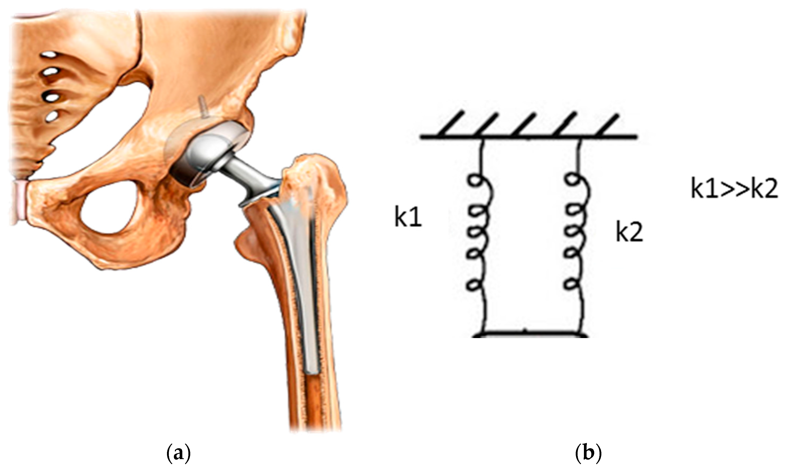
Figure 2.
Stress-shielding example in shoulder replacement surgery; (a) preoperative image; (b) image immediately after the surgery; (c) image after 7 years from the surgery; arrow indicates the region of bone resorption. Reproduced with permission from [36], Elsevier, 2003.
Figure 2.
Stress-shielding example in shoulder replacement surgery; (a) preoperative image; (b) image immediately after the surgery; (c) image after 7 years from the surgery; arrow indicates the region of bone resorption. Reproduced with permission from [36], Elsevier, 2003.

Figure 3.
Stress-time plot of AZ91D alloy tested ate strain rate of 2.2 × 10⁻⁷ s−1 under different environmental conditions. Reproduced with permission from [83], Elsevier, 2012.
Figure 3.
Stress-time plot of AZ91D alloy tested ate strain rate of 2.2 × 10⁻⁷ s−1 under different environmental conditions. Reproduced with permission from [83], Elsevier, 2012.

Figure 4.
Continuous crack propagation according to the film rupture model. Reproduced with permission from [75], John Wiley and Sons, 2005.
Figure 4.
Continuous crack propagation according to the film rupture model. Reproduced with permission from [75], John Wiley and Sons, 2005.
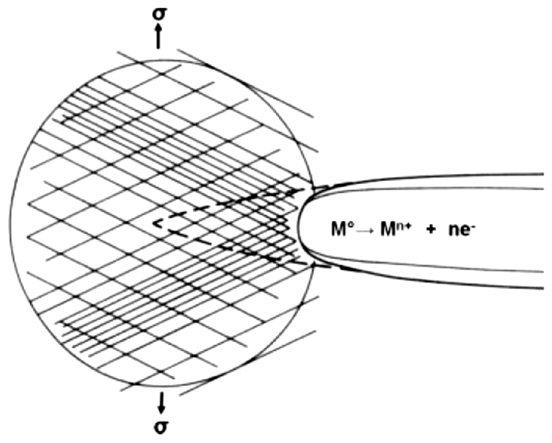
Figure 5.
(a) Tubular pits form due to film rupture on slip steps; (b) crack propagation occurs by ductile tearing of remaining ligaments. Reproduced with permission from [75], John Wiley and Sons, 2005.
Figure 5.
(a) Tubular pits form due to film rupture on slip steps; (b) crack propagation occurs by ductile tearing of remaining ligaments. Reproduced with permission from [75], John Wiley and Sons, 2005.

Figure 6.
Preferential corrosion of Mg matrix along the precipitates. Modified from [75].
Figure 6.
Preferential corrosion of Mg matrix along the precipitates. Modified from [75].

Figure 7.
Model for mechanical induced cracking. Reproduced with permission from [75], John Wiley and Sons, 2005.
Figure 7.
Model for mechanical induced cracking. Reproduced with permission from [75], John Wiley and Sons, 2005.
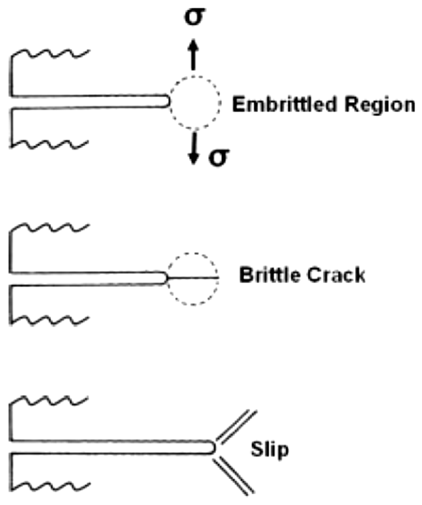
Figure 8.
Fractographic analyses of AZ91D alloy sample continuously cathodically charged and simultaneously tested in modified simulated body fluid (m-SBF). Reproduced with permission from [83], Elsevier, 2012.
Figure 8.
Fractographic analyses of AZ91D alloy sample continuously cathodically charged and simultaneously tested in modified simulated body fluid (m-SBF). Reproduced with permission from [83], Elsevier, 2012.

Figure 9.
Paris curve (red line); Paris-like curve for Stress Corrosion Cracking (SCC) (black line).
Figure 9.
Paris curve (red line); Paris-like curve for Stress Corrosion Cracking (SCC) (black line).

Figure 10.
tf-KI plot for determination of KISCC. Reproduced with permission from [83], Elsevier, 2012.
Figure 10.
tf-KI plot for determination of KISCC. Reproduced with permission from [83], Elsevier, 2012.

Figure 11.
Definition of a*.

Figure 12.
Influence of applied stress on the material behaviour in corrosive environment.
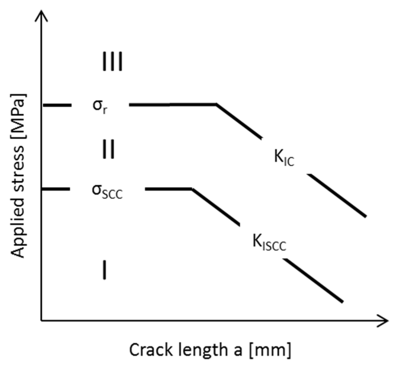
Figure 13.
S-N curve for AZ91D magnesium alloy under different electrochemical conditions. Reproduced with permission from [86], Copyright Elsevier, 2015.
Figure 13.
S-N curve for AZ91D magnesium alloy under different electrochemical conditions. Reproduced with permission from [86], Copyright Elsevier, 2015.
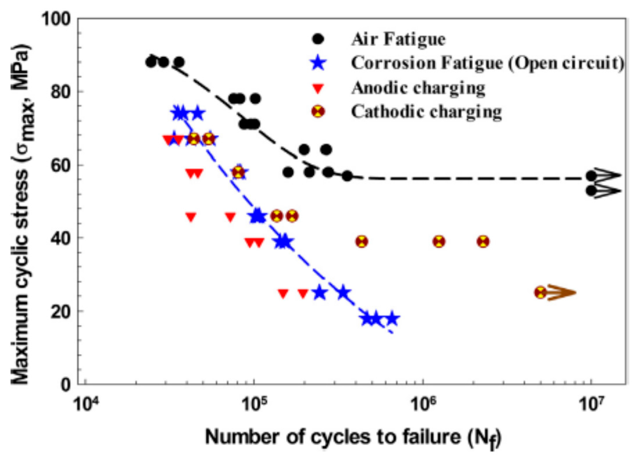
Figure 14.
Schematic representation of crack growth rate under different combinations of static and dynamic loading in inert and corrosive environments. Crack growth rate depending on stress intensity factor in (a) pure corrosion fatigue (CF), (b) stress and (c) time-stress dependent SCC and CF combinations. Reproduced with permission from [115], Elsevier, 2009.

Figure 15.
Schematic representation of negative different effect. Reproduced with permission from [118], Elsevier, 1997.
Figure 15.
Schematic representation of negative different effect. Reproduced with permission from [118], Elsevier, 1997.
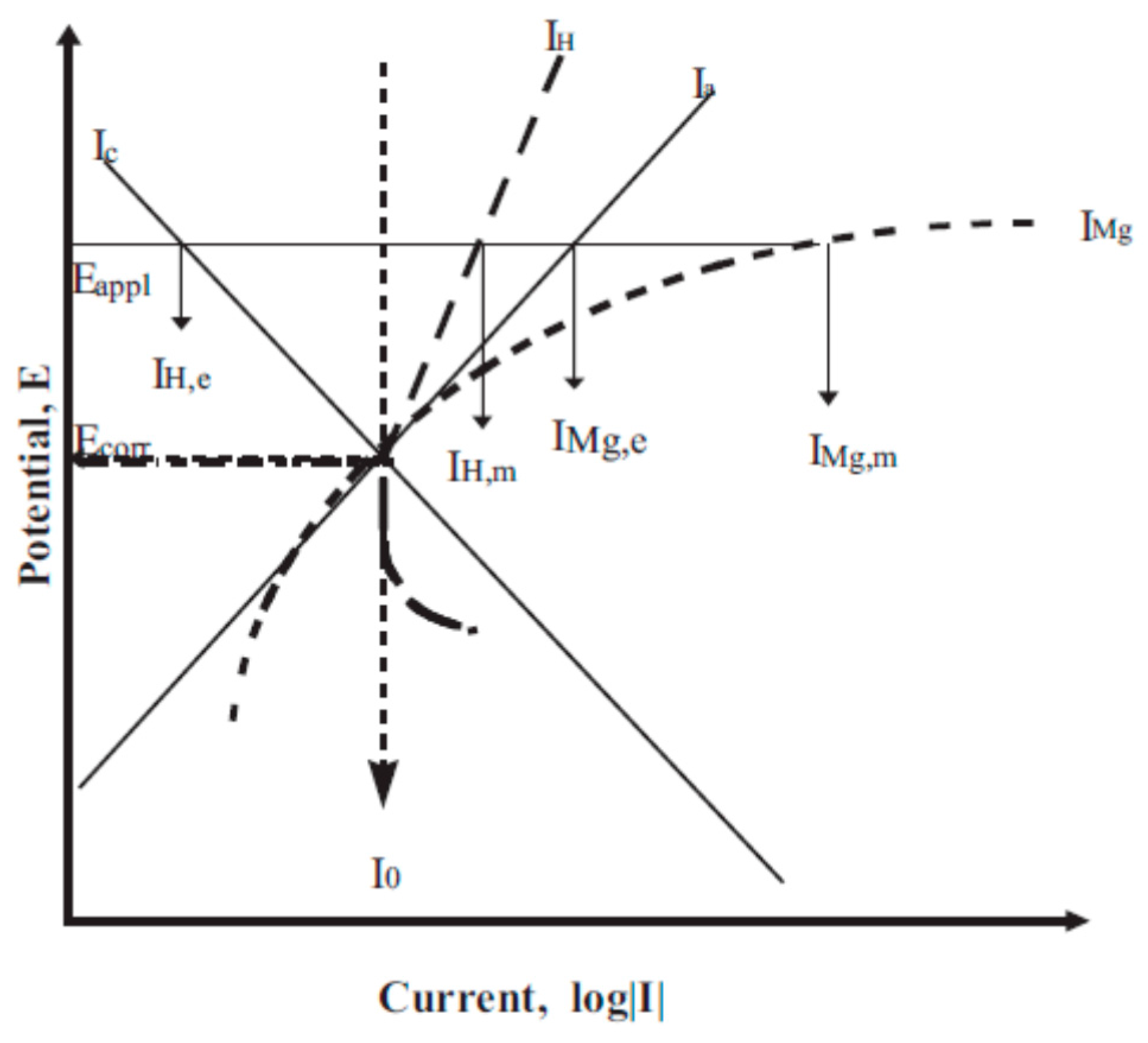
Figure 16.
Model of partially protective surface film at low (a) and high (b) applied potential (E) or current (I). Modified from [85].
Figure 16.
Model of partially protective surface film at low (a) and high (b) applied potential (E) or current (I). Modified from [85].

Figure 17.
Monovalent magnesium ion model. Modified from [85].
Figure 17.
Monovalent magnesium ion model. Modified from [85].
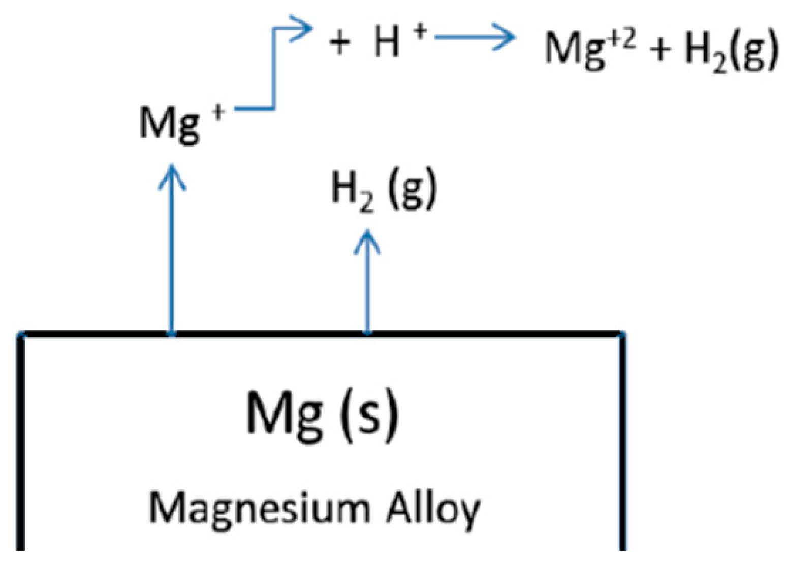
Figure 18.
Particle undermining model, at low (a) and high (b) current density or potential. Modified from [77].
Figure 18.
Particle undermining model, at low (a) and high (b) current density or potential. Modified from [77].

Figure 19.
Magnesium hydride MgH2 model, modified from [77]
Figure 19.
Magnesium hydride MgH2 model, modified from [77]
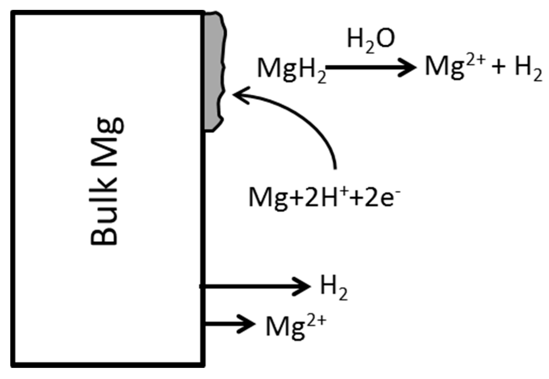
Figure 20.
Comparison of the corrosion rates of the high purity (HP) with low purity Mg (CP) in the salt immersion test (3% NaCl SIT) and salt spray test (SST). Reproduced with permission from [126], Elsevier, 2006.
Figure 20.
Comparison of the corrosion rates of the high purity (HP) with low purity Mg (CP) in the salt immersion test (3% NaCl SIT) and salt spray test (SST). Reproduced with permission from [126], Elsevier, 2006.

Figure 21.
Tolerance limits for Nickel in pure Mg and Mg-Zn and Mg-Mn alloys. Modified from [129].
Figure 21.
Tolerance limits for Nickel in pure Mg and Mg-Zn and Mg-Mn alloys. Modified from [129].

Figure 22.
Effect of Cu in a Mg-Al-Mn-Zn alloy. Modified from [129].
Figure 22.
Effect of Cu in a Mg-Al-Mn-Zn alloy. Modified from [129].
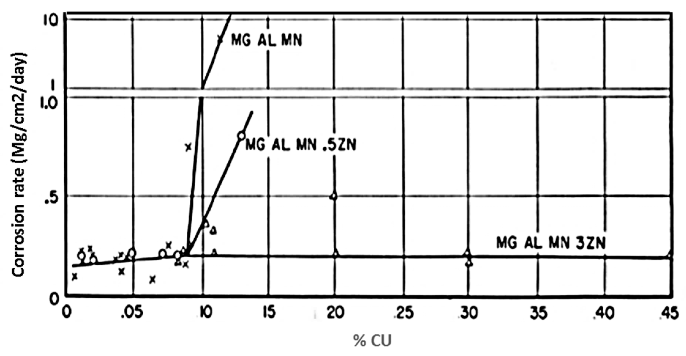
Figure 23.
Corrosion interface of AZ21 alloy. Reproduced with permission from [99], Elsevier, 1998.
Figure 23.
Corrosion interface of AZ21 alloy. Reproduced with permission from [99], Elsevier, 1998.

Figure 24.
Mg-Al phase diagram. Reprinted with permission from [135].
Figure 24.
Mg-Al phase diagram. Reprinted with permission from [135].
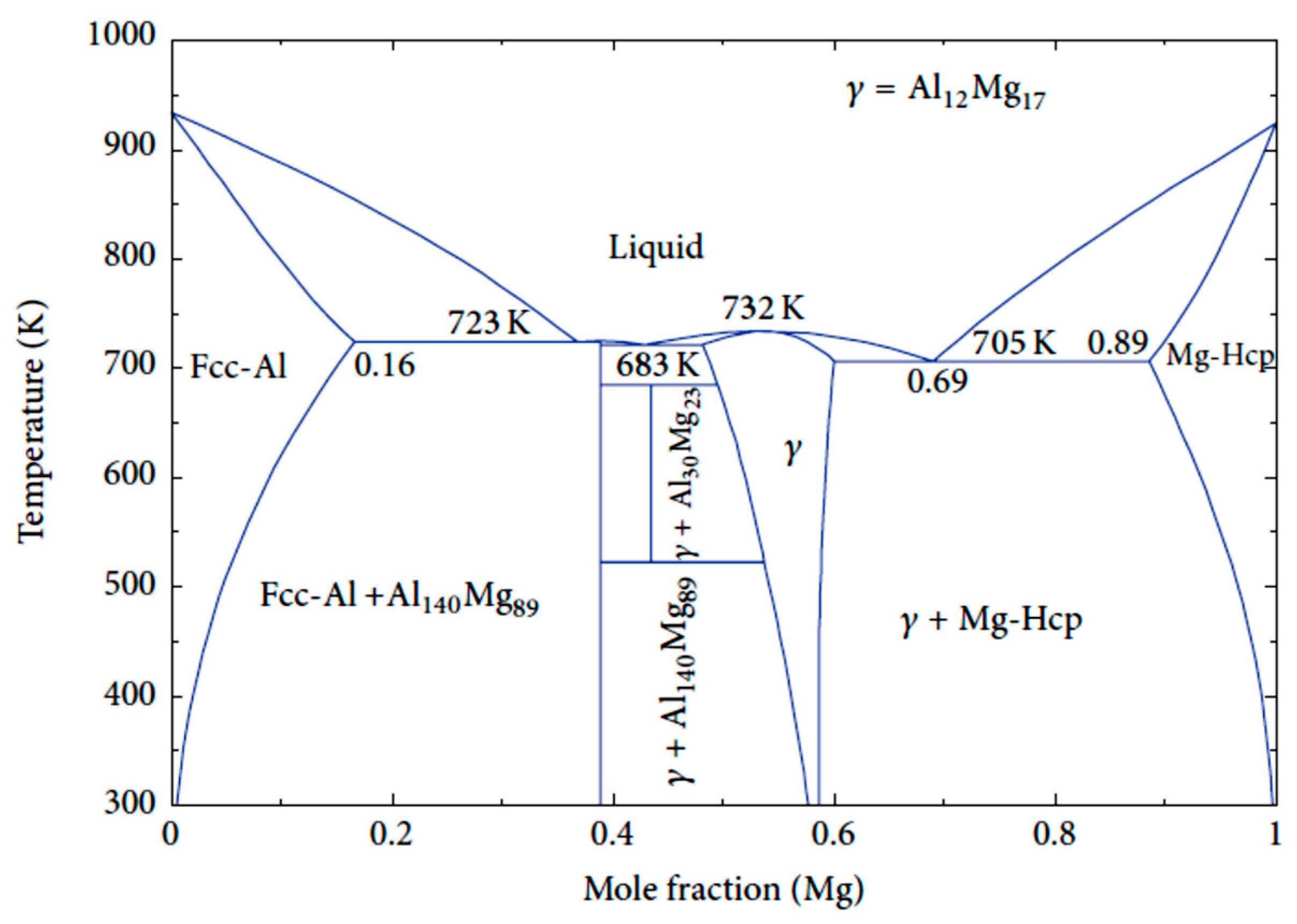
Figure 25.
Schematic illustration of the role of Mg17Al12 phases in the Mg matrix whether their distribution is continuous (a) or discontinuous (b). Reproduced with permission from [139], Elsevier, 2014.
Figure 25.
Schematic illustration of the role of Mg17Al12 phases in the Mg matrix whether their distribution is continuous (a) or discontinuous (b). Reproduced with permission from [139], Elsevier, 2014.

Figure 26.
Hydrogen evolution measurement for MgZnCa alloys with different content of Zn. Reproduced with permission from [80], Nature Publishing Group, 2009.
Figure 26.
Hydrogen evolution measurement for MgZnCa alloys with different content of Zn. Reproduced with permission from [80], Nature Publishing Group, 2009.
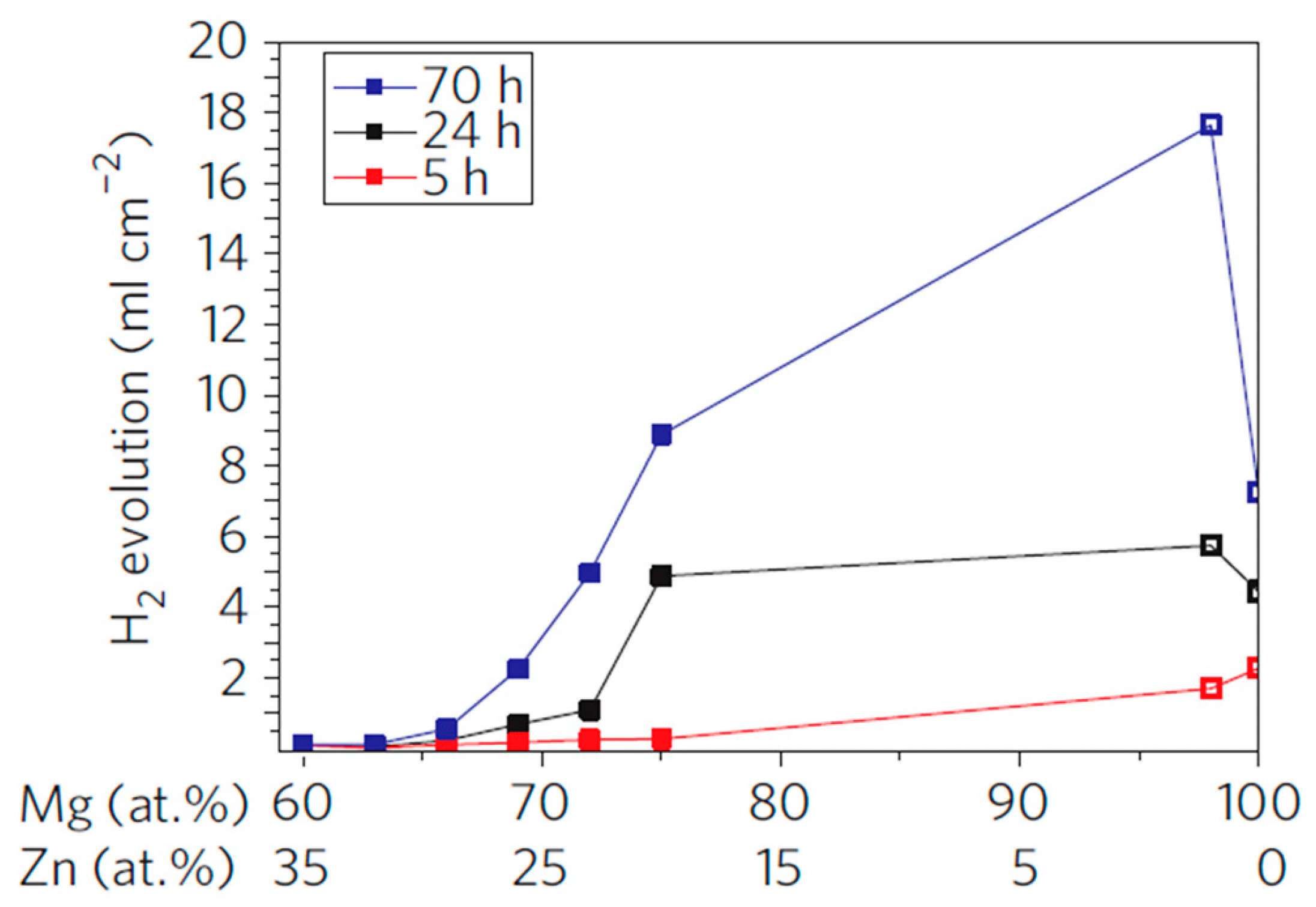
Figure 27.
Weight loss rate for MEZu and MEZr specimens. Modified from [151].
Figure 27.
Weight loss rate for MEZu and MEZr specimens. Modified from [151].
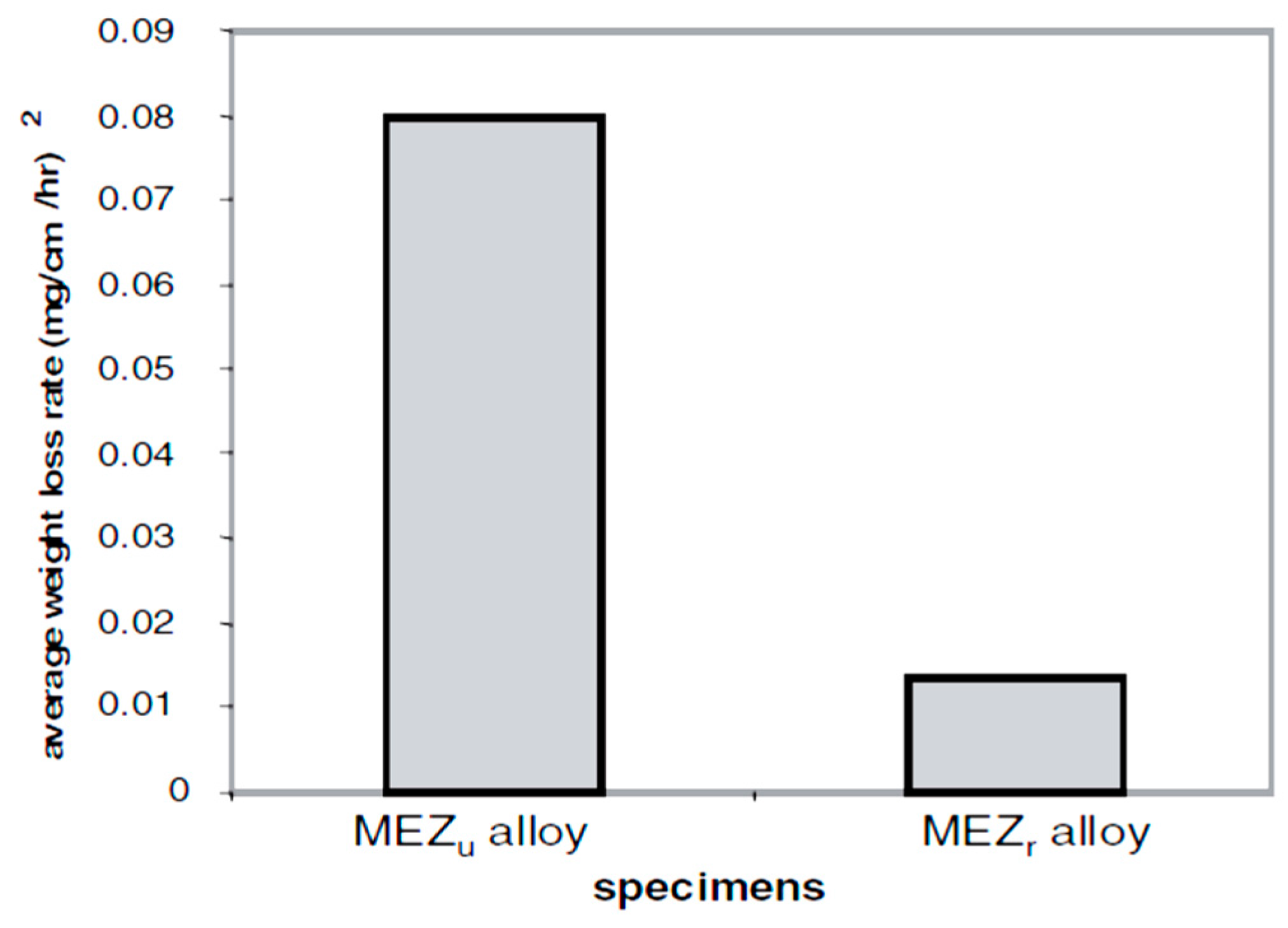
Figure 28.
Optical micrographs of MEZR surface after immersion in chloride solution for 3 h. Reproduced with permission from [151], Elsevier, 2002.
Figure 28.
Optical micrographs of MEZR surface after immersion in chloride solution for 3 h. Reproduced with permission from [151], Elsevier, 2002.
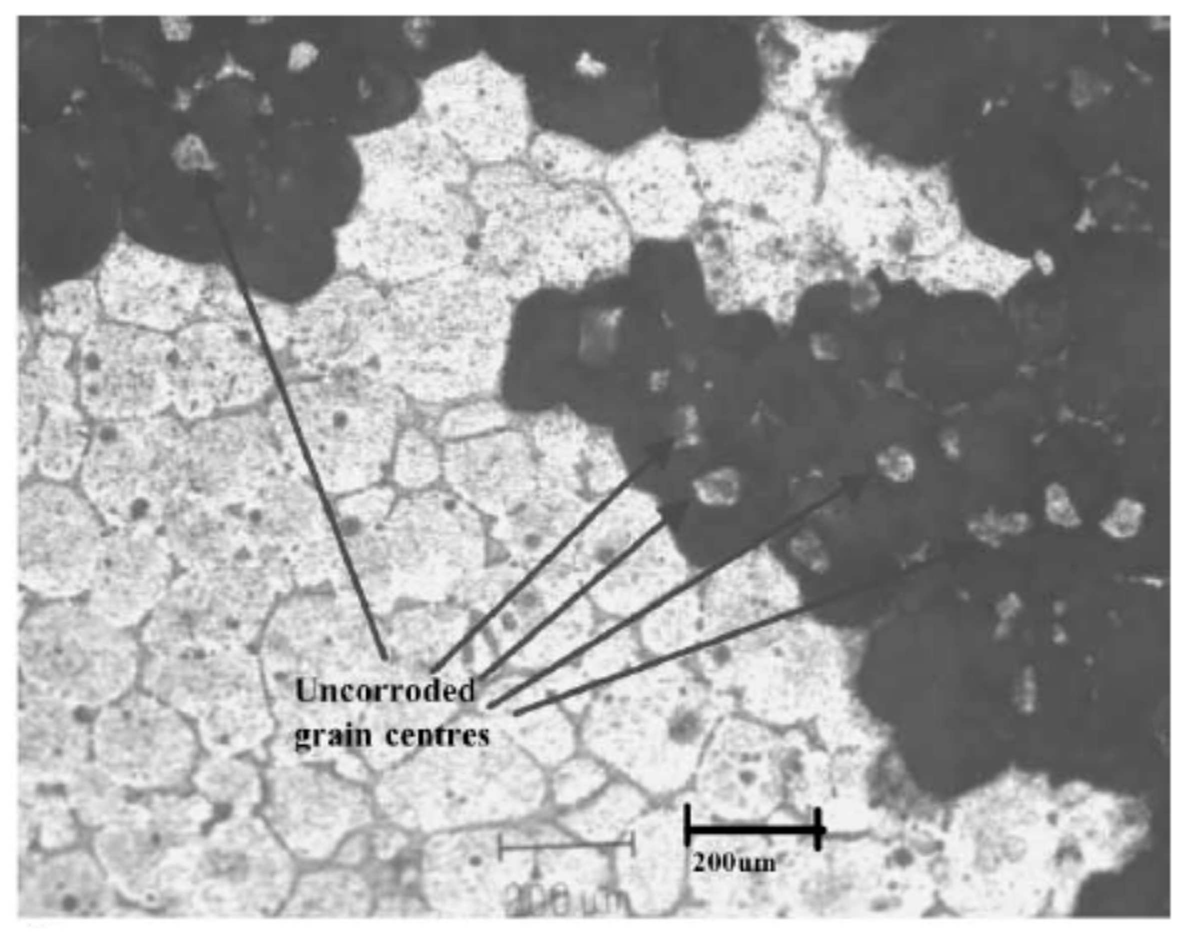
Figure 29.
Corrosion rate of pure Mg, binary and ternary alloys in SBF at 37 °C. Reproduced with permission from [156], Elsevier, 2014.
Figure 29.
Corrosion rate of pure Mg, binary and ternary alloys in SBF at 37 °C. Reproduced with permission from [156], Elsevier, 2014.

Figure 30.
Corrosion rate of AZ91 with and without Nd. Reproduced with permission from [159], Elsevier, 2011.
Figure 30.
Corrosion rate of AZ91 with and without Nd. Reproduced with permission from [159], Elsevier, 2011.
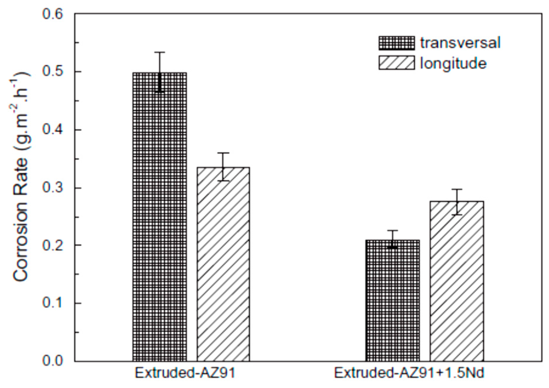
Figure 31.
Corrosion current densities (iH) of AZ91 alloy varied with different immersion time. Reproduced with permission from [160], John Wiley and Sons, 2009.
Figure 31.
Corrosion current densities (iH) of AZ91 alloy varied with different immersion time. Reproduced with permission from [160], John Wiley and Sons, 2009.

Figure 32.
Corrosion rate of AZ91D with and without Ho. Reproduced with permission from [161], Elsevier, 2006.
Figure 32.
Corrosion rate of AZ91D with and without Ho. Reproduced with permission from [161], Elsevier, 2006.

Figure 33.
Hydrogen evolution of WE43 specimens in SBF at 37 °C after various heat treatment. Reproduced with permission from [164], Elsevier, 2009.
Figure 33.
Hydrogen evolution of WE43 specimens in SBF at 37 °C after various heat treatment. Reproduced with permission from [164], Elsevier, 2009.

Figure 34.
Maximum hydrogen evolution rate for different WE43 samples. Reproduced with permission from [164], Elsevier, 2009.
Figure 34.
Maximum hydrogen evolution rate for different WE43 samples. Reproduced with permission from [164], Elsevier, 2009.
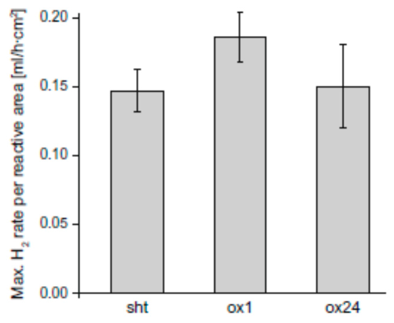
Figure 35.
Hydrogen evolution of Mg-Zn alloys with and without Ca-P coatings in m-SBF. Reproduced with permission from [167], Elsevier, 2010.
Figure 35.
Hydrogen evolution of Mg-Zn alloys with and without Ca-P coatings in m-SBF. Reproduced with permission from [167], Elsevier, 2010.
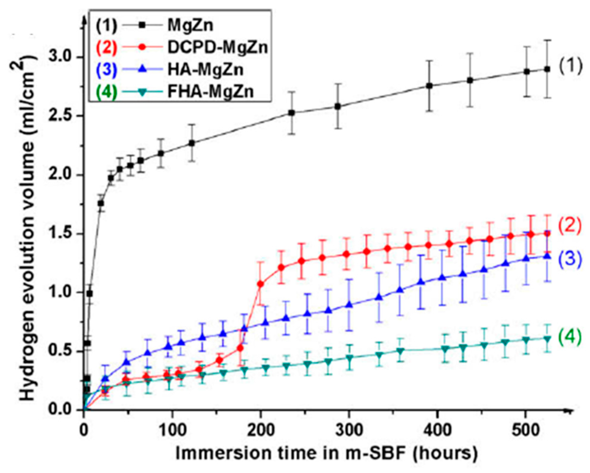
Figure 36.
Implant volume of LAE442 and MgF2-coated LAE442 at different postoperative intervals. Reproduced with permission from [172], Elsevier, 2010.
Figure 36.
Implant volume of LAE442 and MgF2-coated LAE442 at different postoperative intervals. Reproduced with permission from [172], Elsevier, 2010.

Figure 37.
SEM micrographs of cell morphology after various culture times on polylactic-co-glycolic acid (PLGA) coated Mg alloys after (a) 1 day; (b) 2 days and (c) 3 days culture and uncoated PLGA after (d) 1 day; (e) 2 days and (f) 3 days culture. Reprinted with permission from [173], Springer, 2010.


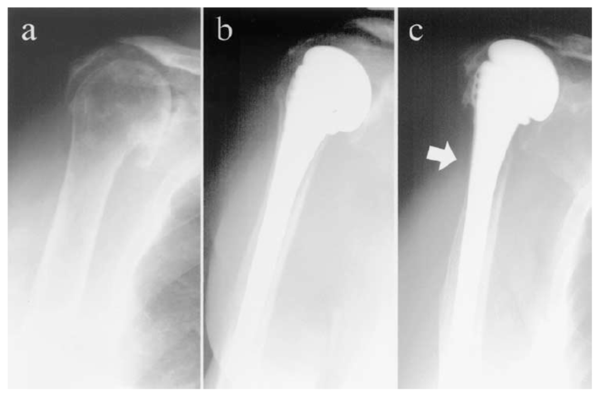
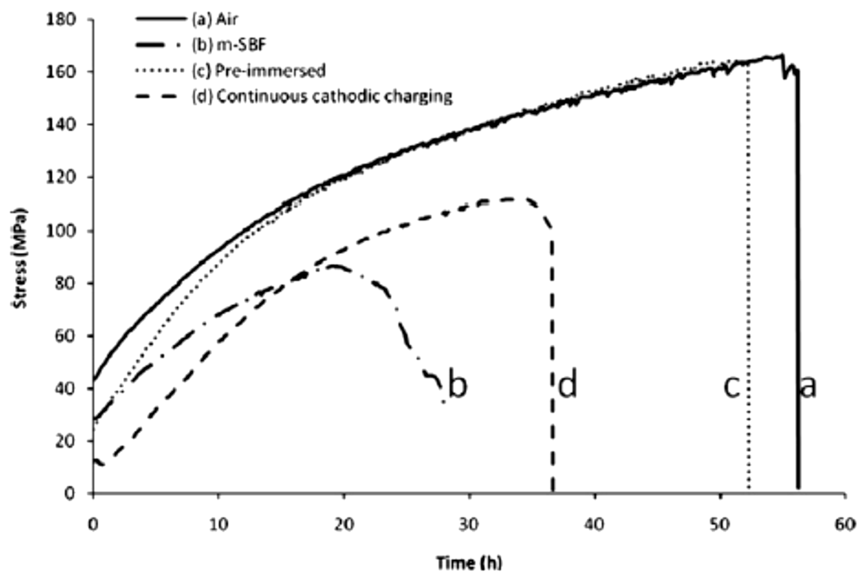
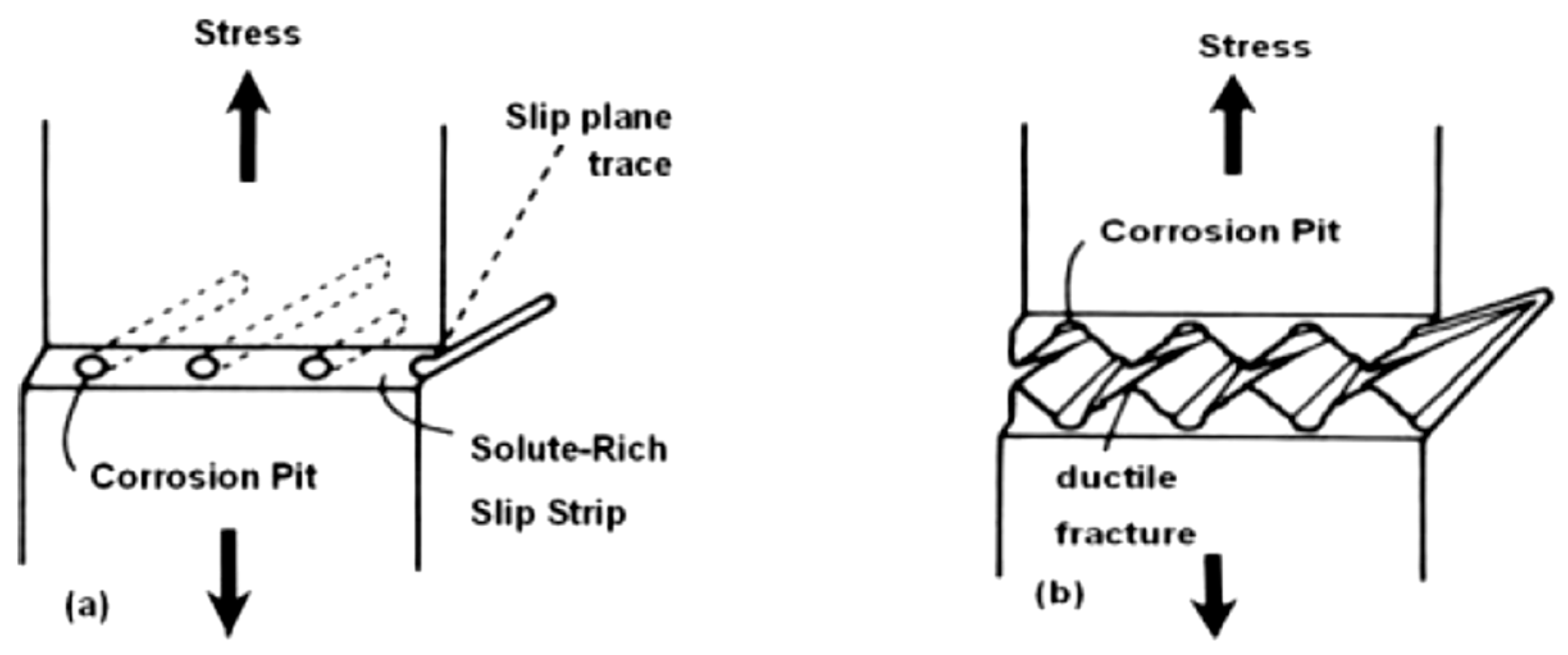
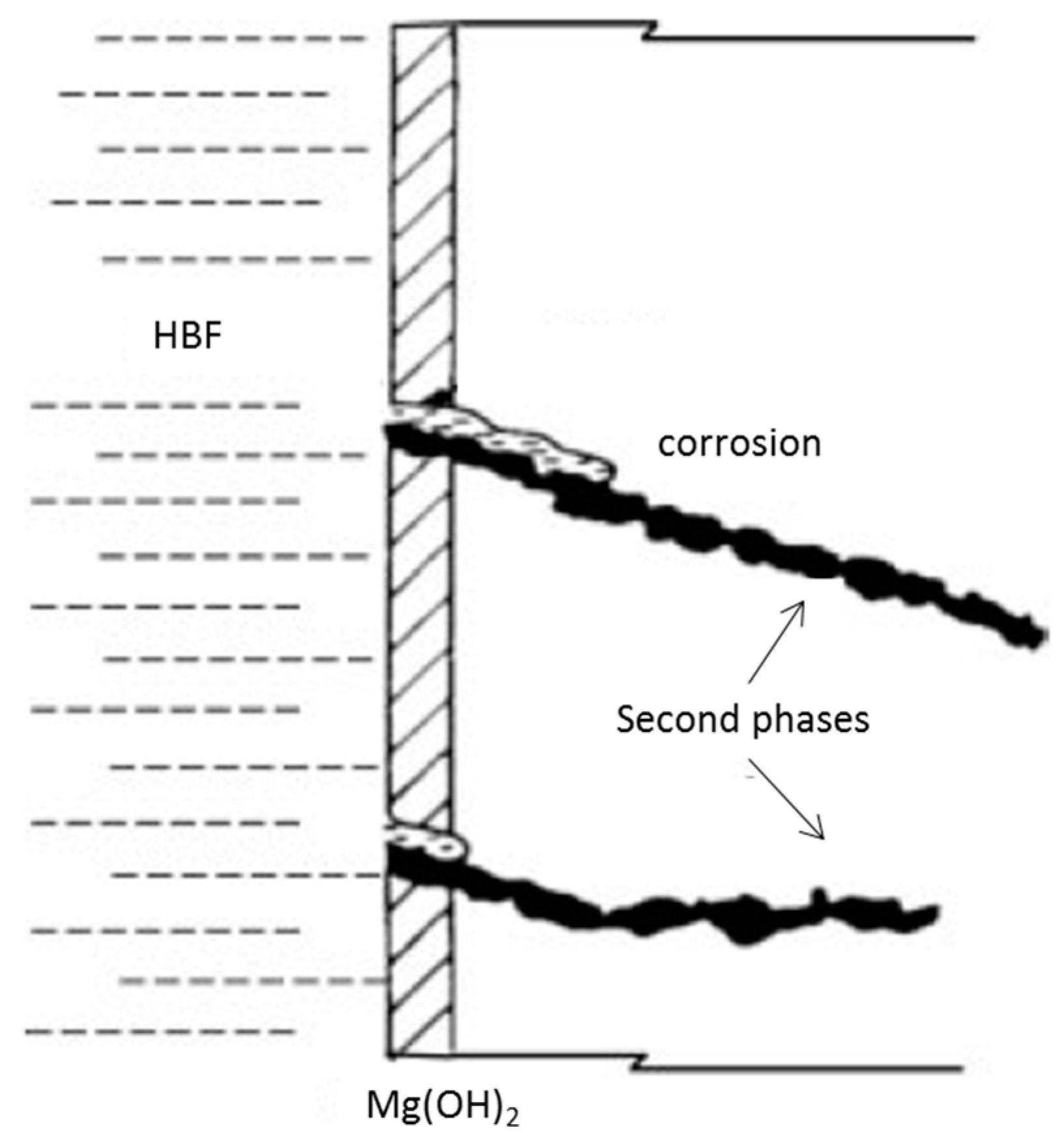
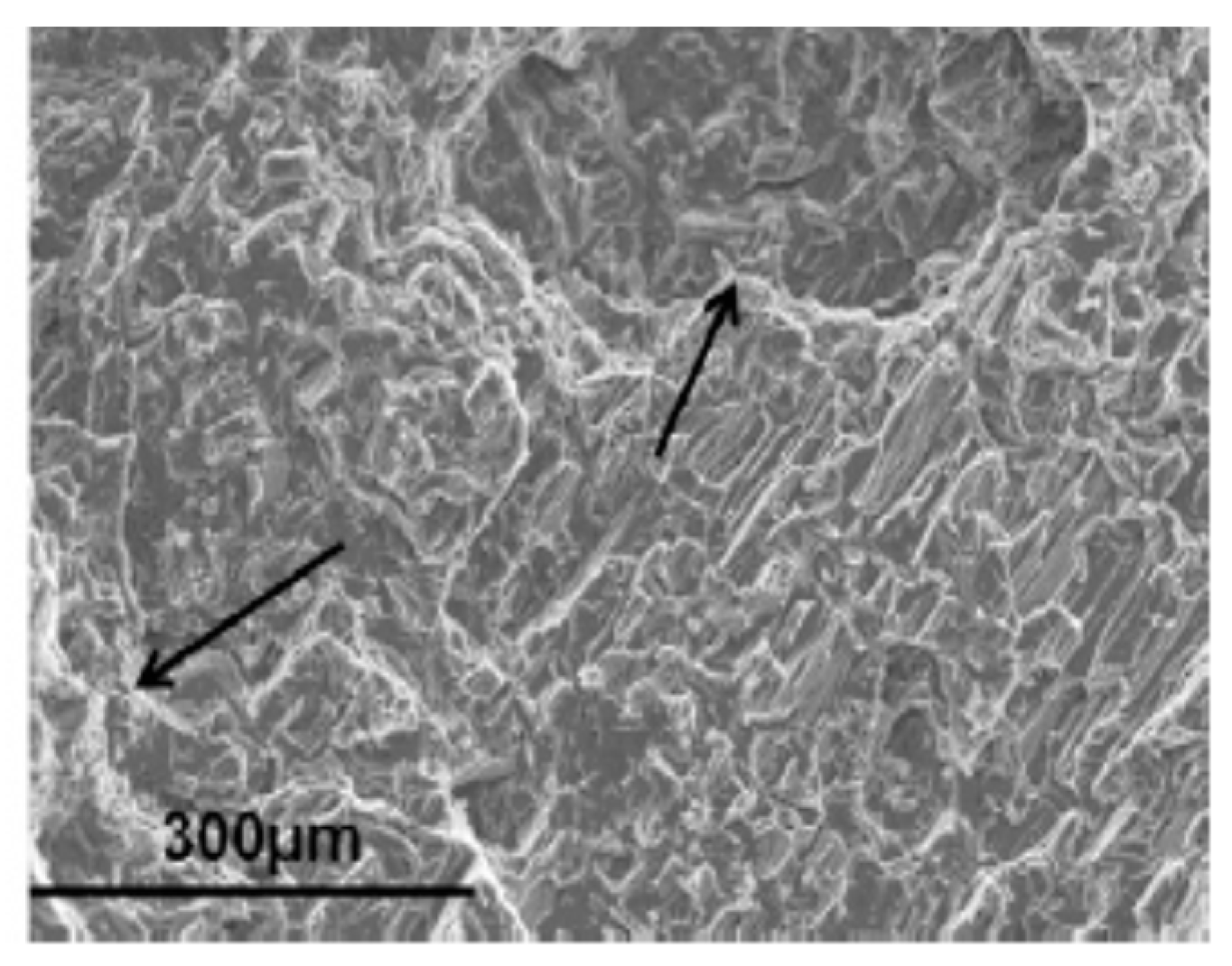
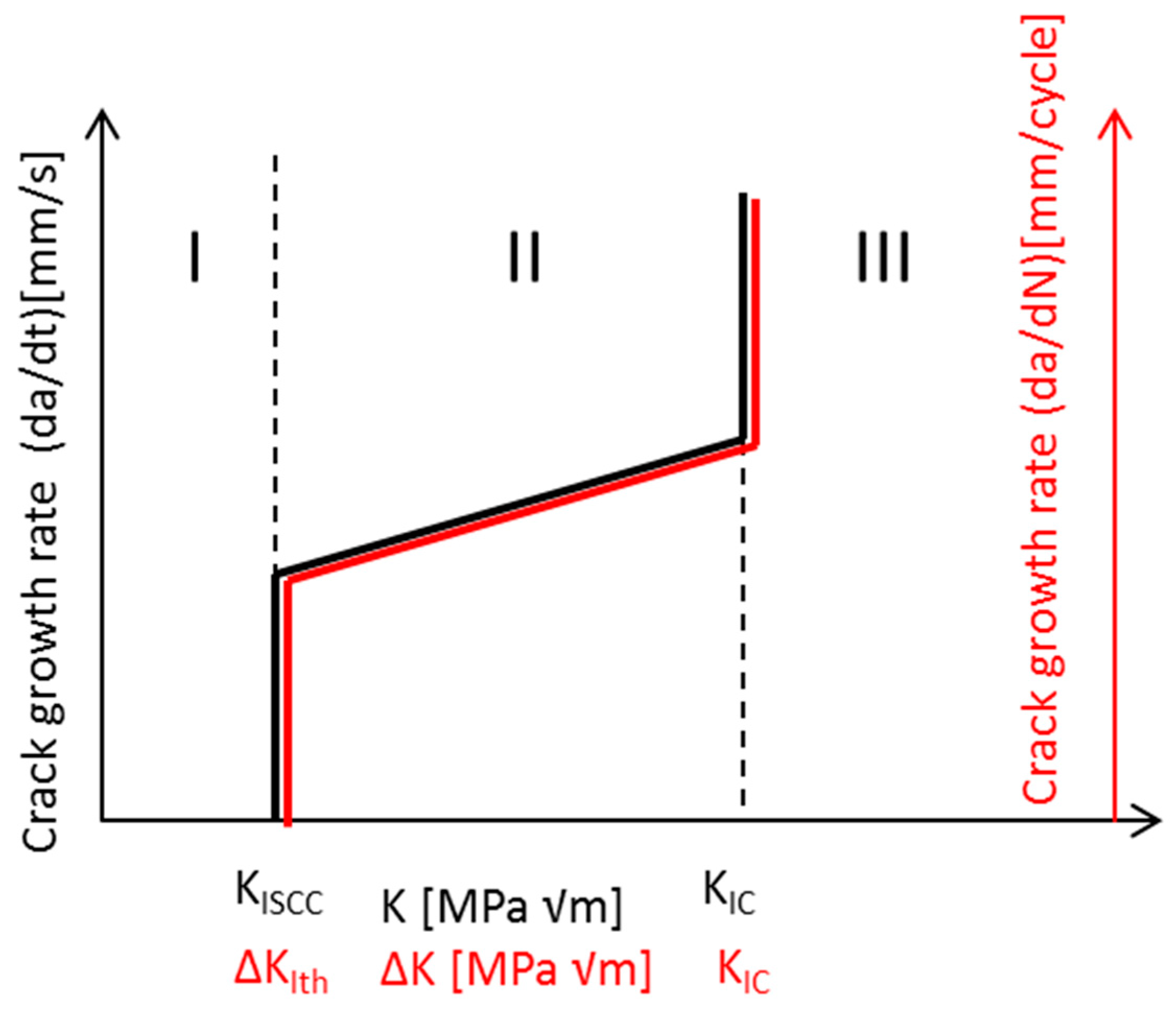
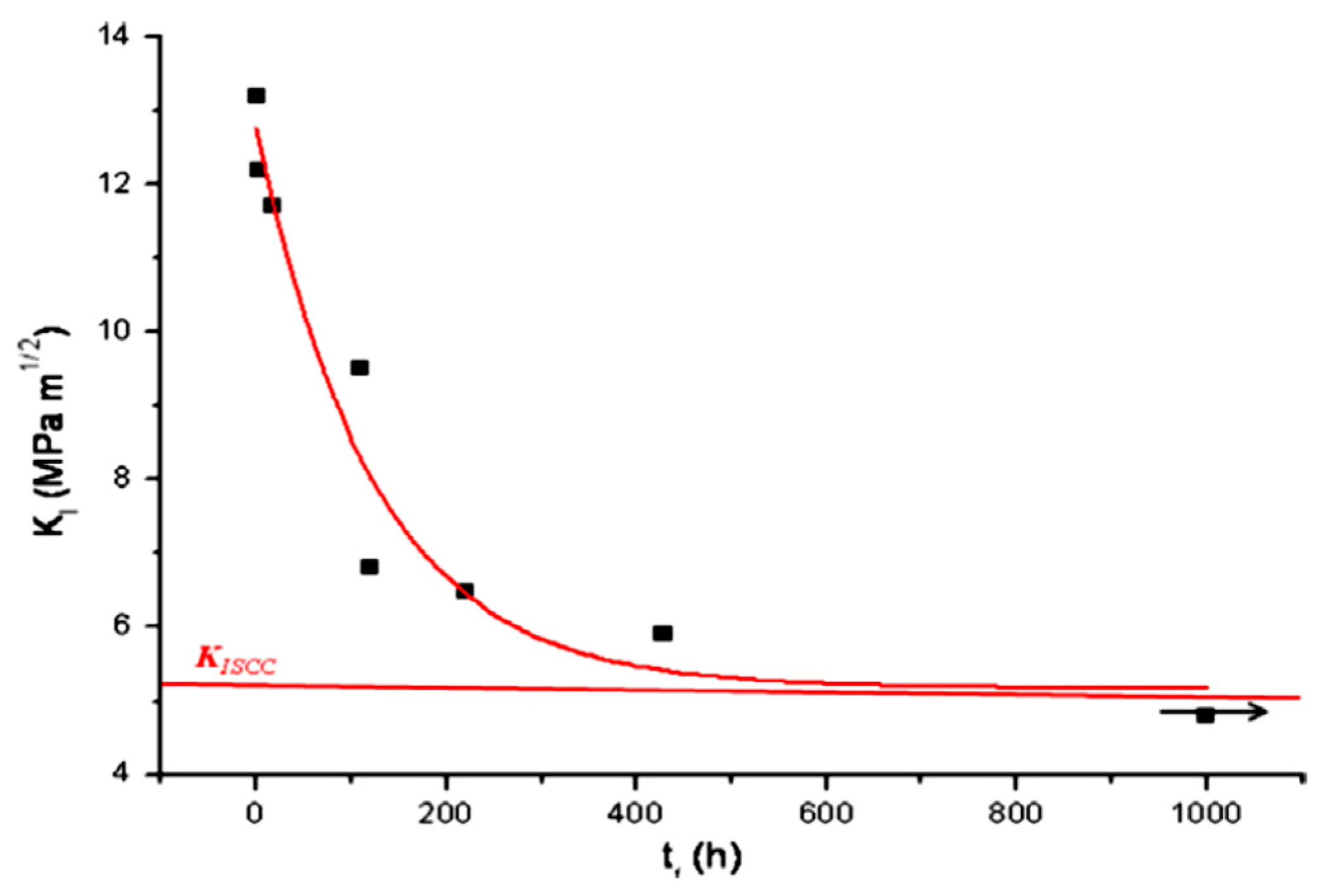
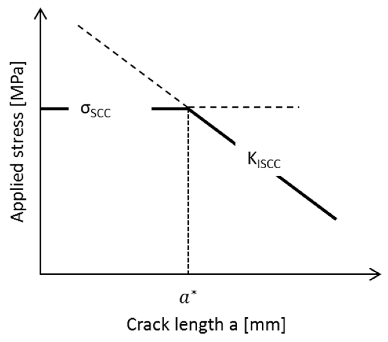
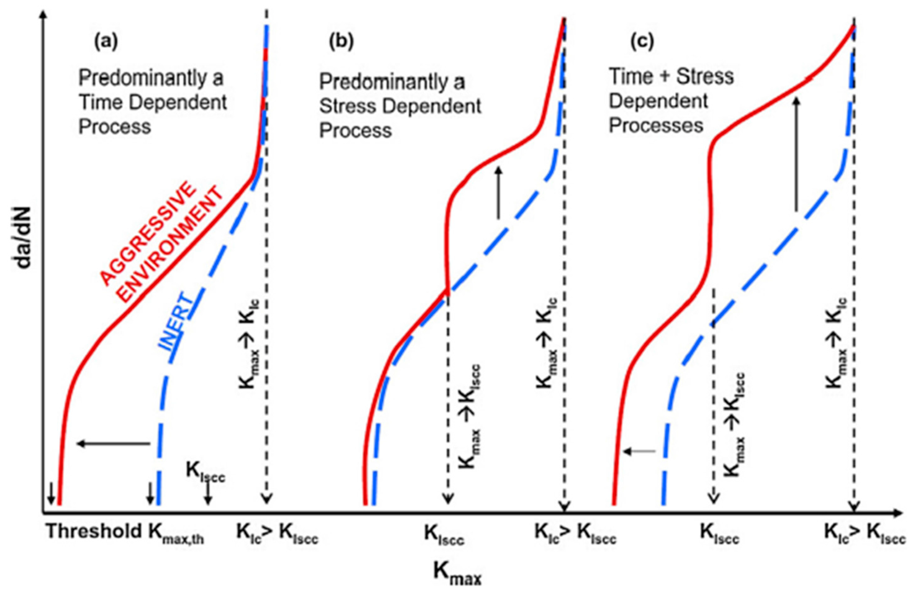
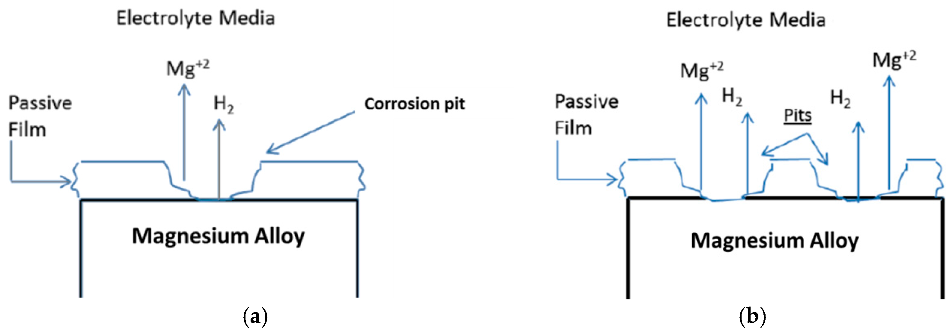
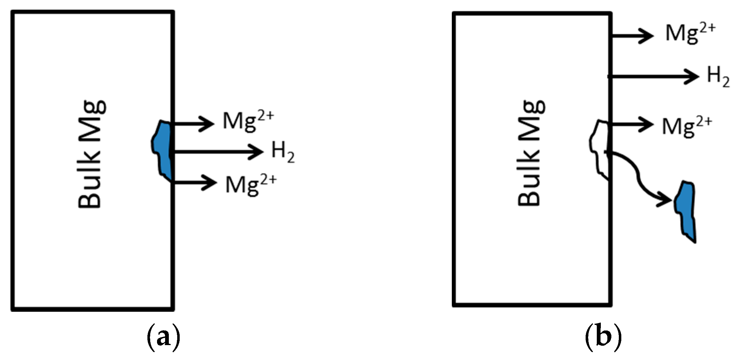
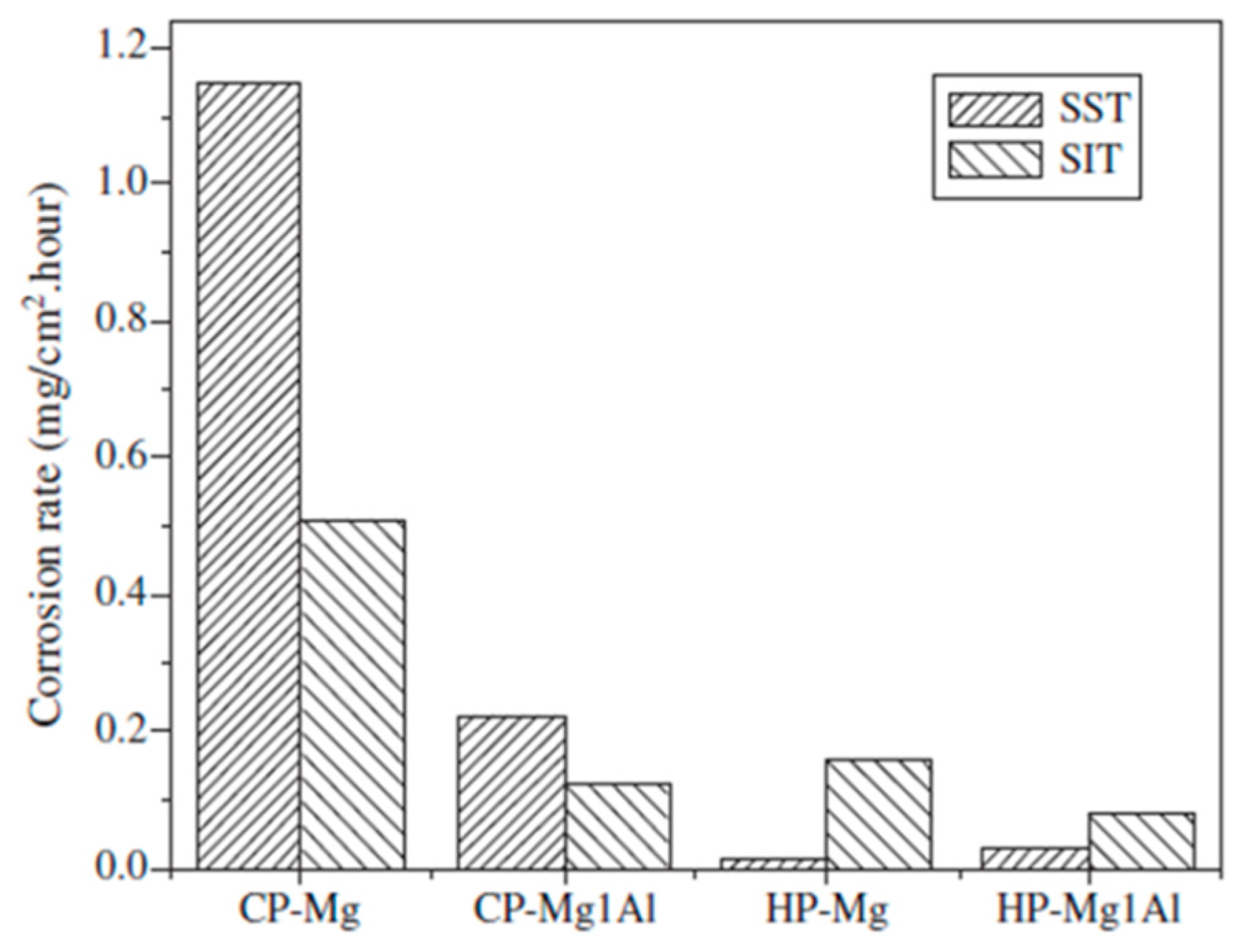
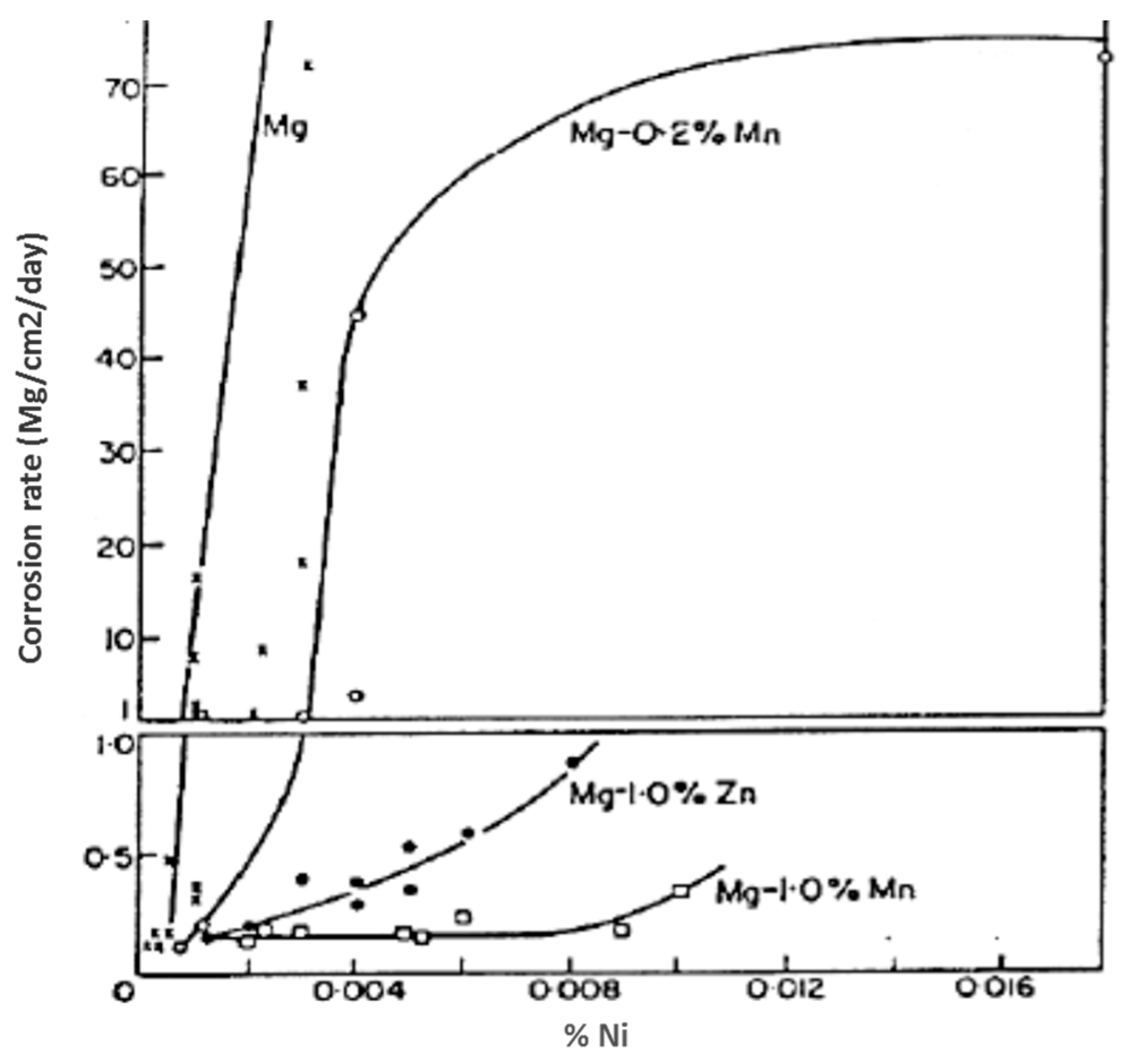
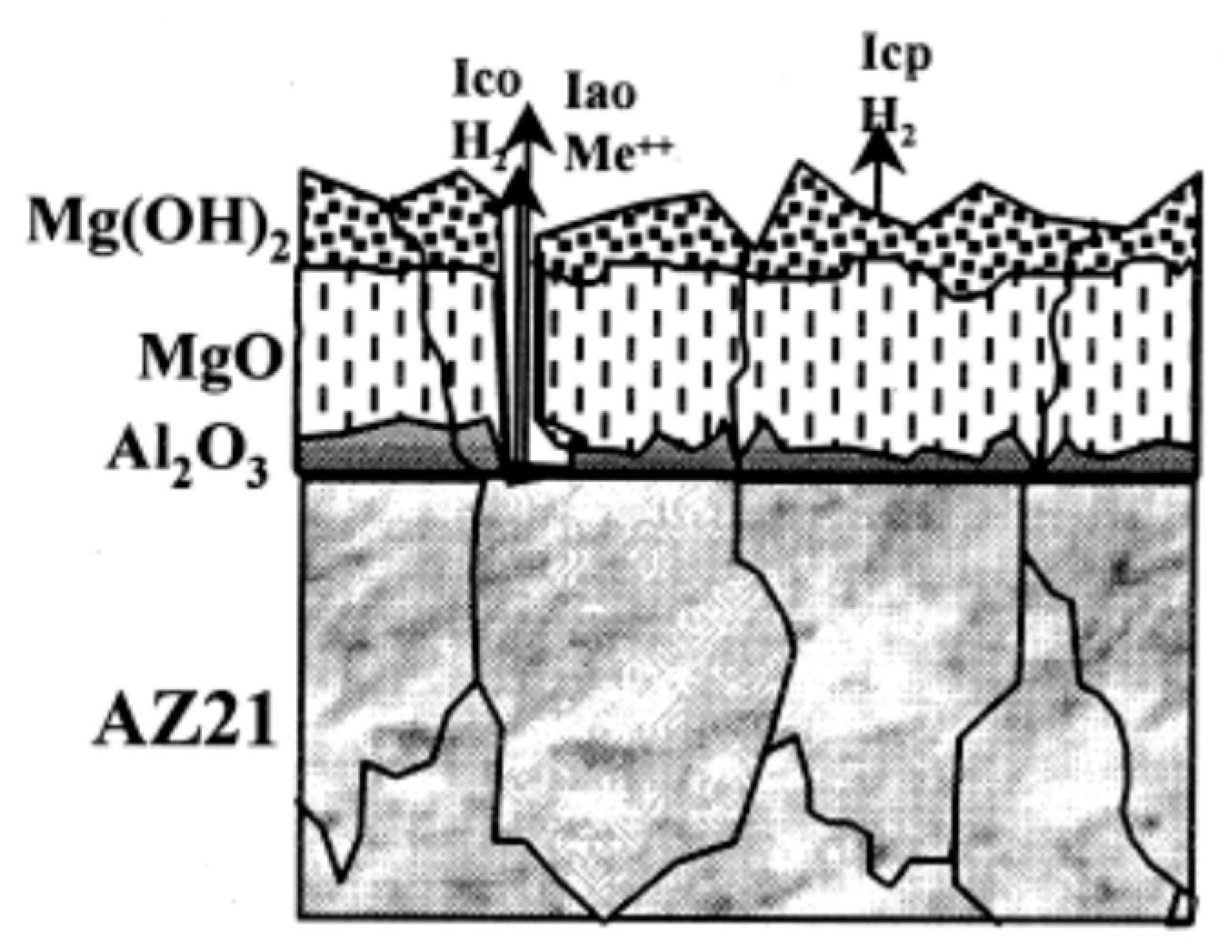
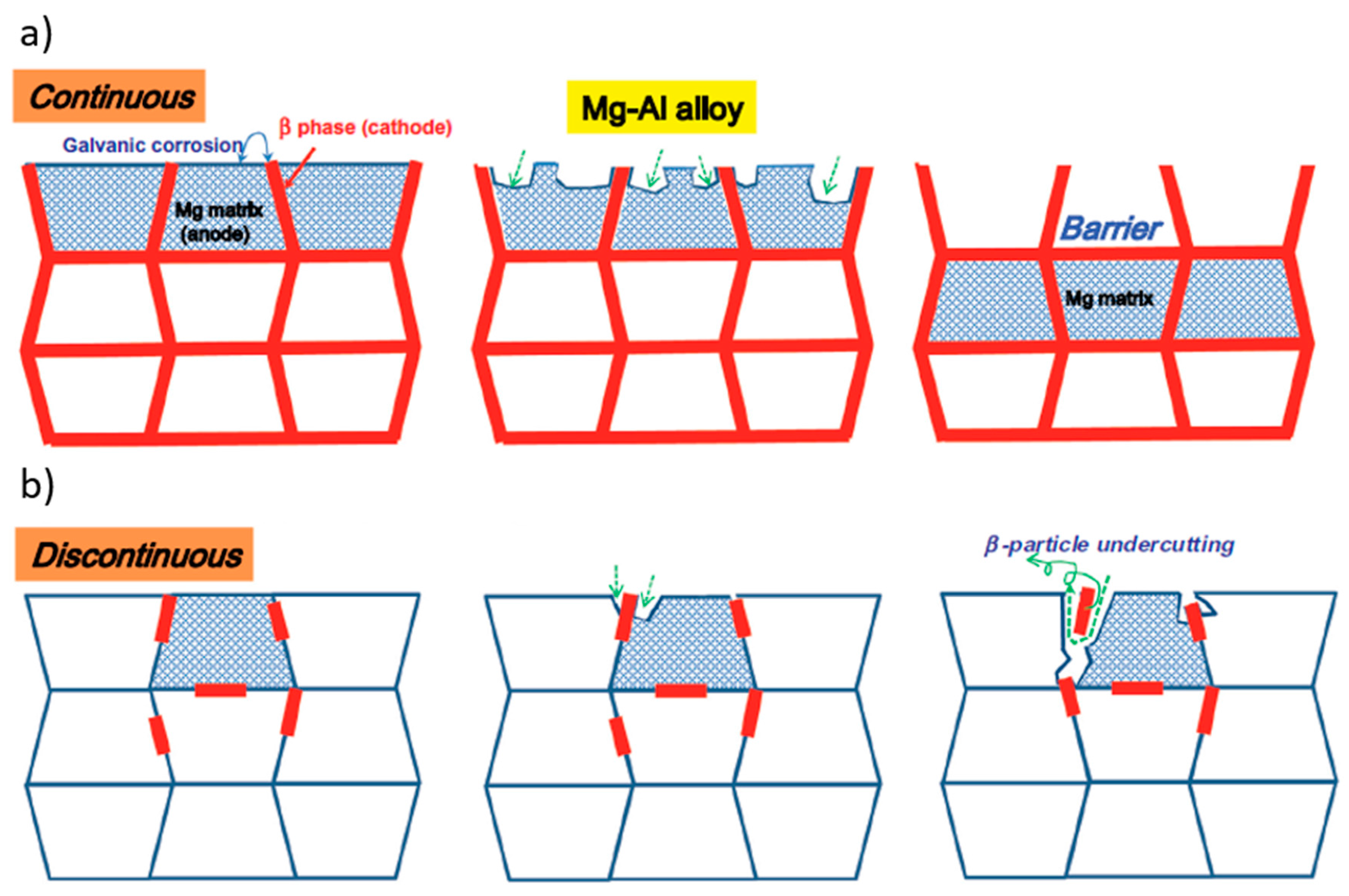
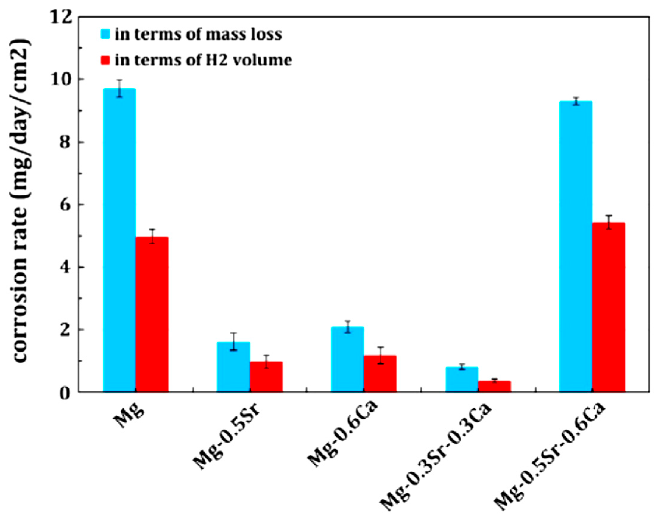
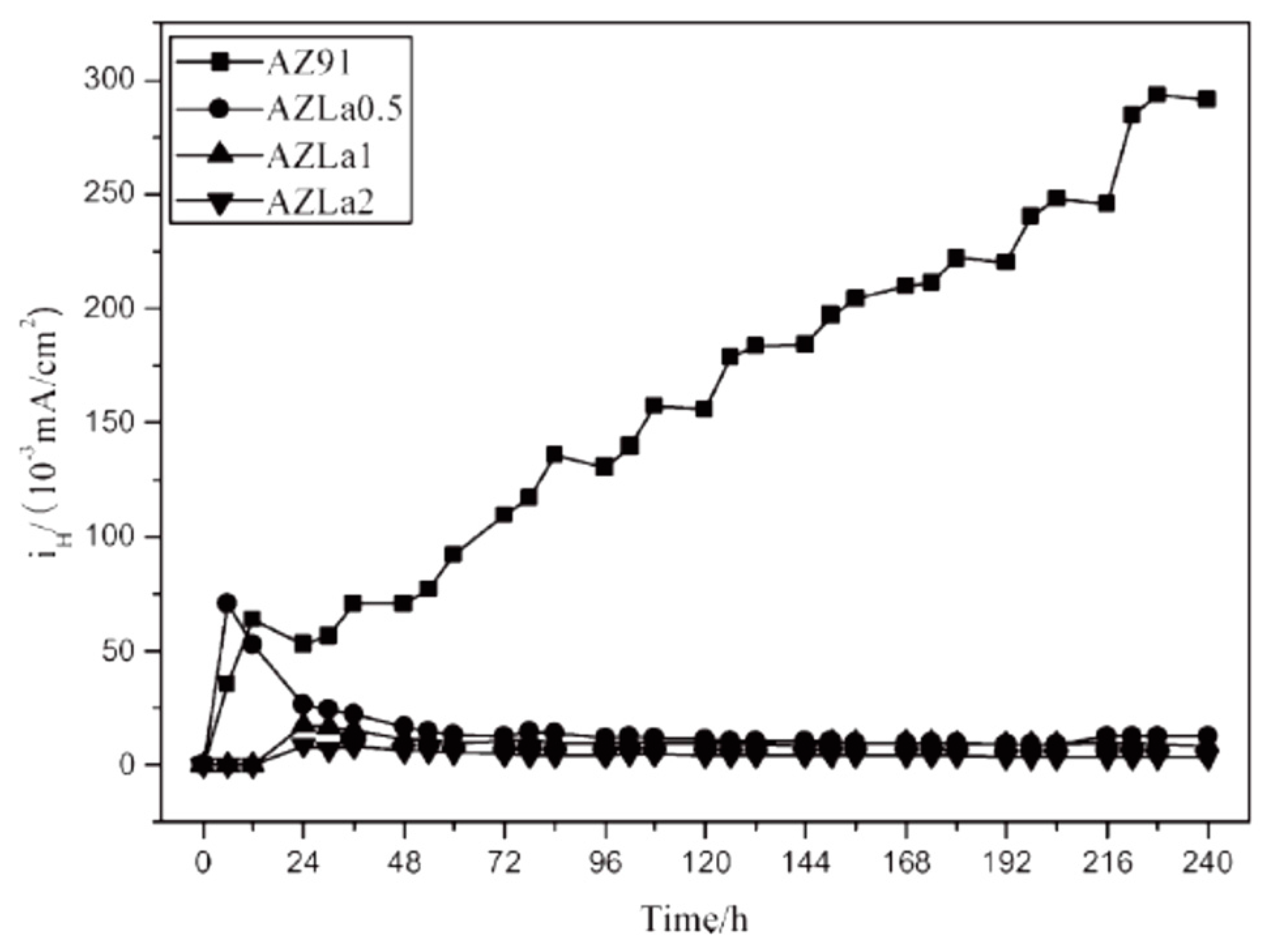
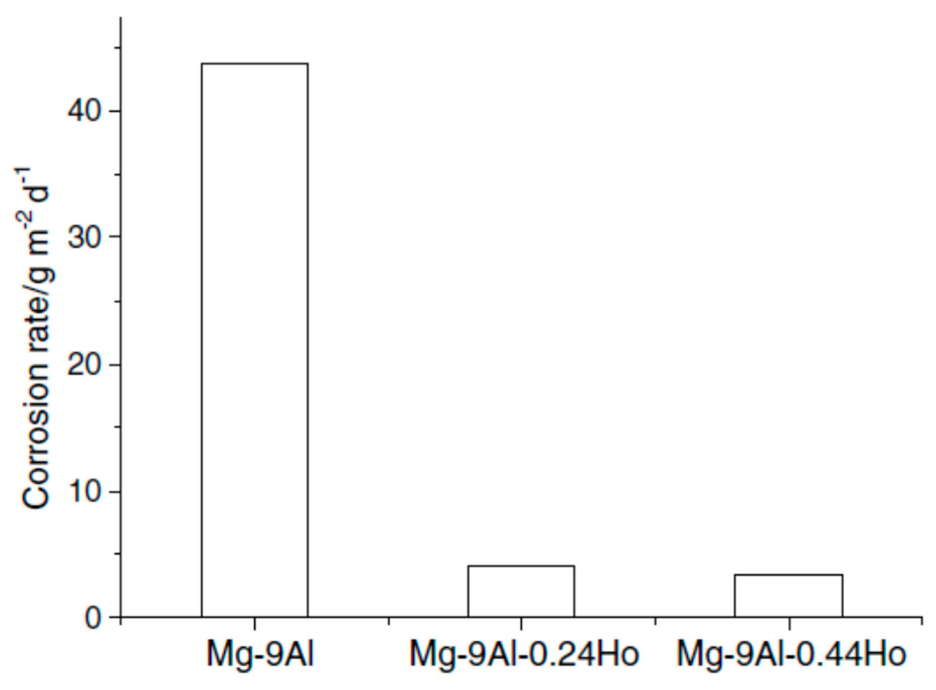
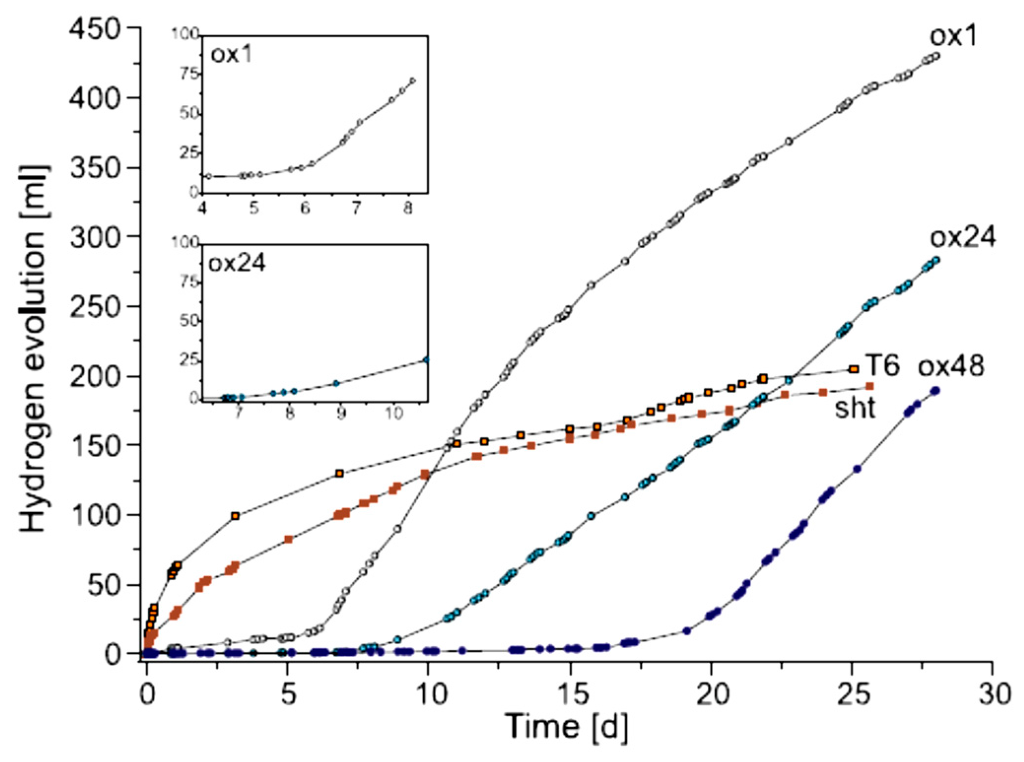
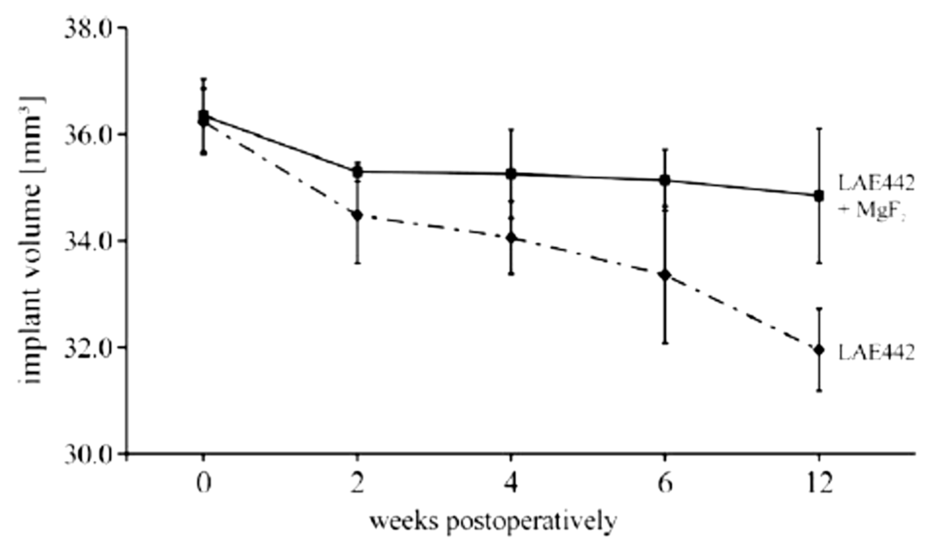
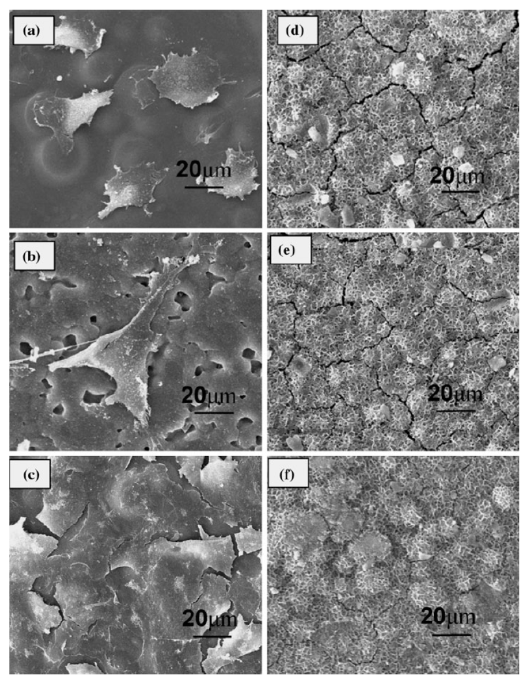
| Application | Material |
|---|---|
| Spinal fixation | stainless steel; Ti, Ti alloys |
| Bone fixation (bone plate, screw, wire, bone nail, etc.) | stainless steel; Ti, Ti alloys; PMMA; PS; CF/PEEK; CF/Epoxy; CF/PS; |
| Bio-Glass/PU; Bio-Glass/PS; PET/SR; PET/Hydrogel; CF/LCP; GF/PEEK; | |
| Bone particles/PMMA; Ti/PMMA; UHMWPE/PMMA; UHMWPE; | |
| GF/PMMA; CF/PMMA; KF/PMMA; PMMA/PMMA; Bio-Glass/Bis-GMA; | |
| CF/PP; CF/PS; CF/PLLA; CF/PLA; KF/PC; HA/PE; PLLA/PLDLA; | |
| PGA/PGA; Alumina; Zirconia; Tricalcium phosphate; | |
| Bio-Glass-Metal fiber composite; Bio-Glass | |
| Artificial joint | Co-Cr-Mo alloy; Ti alloys; Alumina; Zirconia; PET/SR;CF/UHMWPE; |
| PET/Hydrogel; CF/Epoxy; CF/C; CF/PS; CF/PEEK; CF/PTFE; CF/UHMWPE; | |
| CF/PE; UHMWPE/UHMWPE; HA/HDPE; Metal Bio-Glass coatings | |
| Spinal spacer | stainless steel; Ti alloys |
| Dental implant and bridge | Ti; Ti alloys; Au; CF/C; SiC/C; Alumina; Bio-Glass; HA; |
| Bio-Glass coated alumina; Bio-Glass coated vitallium; Au-Cu-Ag; | |
| Au-Cu-Ag-Pt-Pd; UHMWPE/PMMA; CF/PMMA; GF/PMMA; KF/PMMA; | |
| Tendon/Ligament/Cartilage Replacement | PET/PU; PTFE/PU; CF/PTFE; CF/C; PET/PHEMA; KF/PMA; KF/PE; |
| CF/PTFE; CF/PLLA; GF/PU; PP; ePTFE; PET/PET; PA; PU; PLGA |
Table 2.
Comparison of the mechanical properties of natural bone with various implant materials [11,15,19,43,44,45,46].
| Properties | Natural Bone | Stainless Steel | Ti Alloy | Co-Cr Alloy | Magnesium |
|---|---|---|---|---|---|
| Density (g/cm3) | 1.7–2.0 | 7.9–8.1 | 4.4–4.5 | 8.3–9.2 | 1.74–2.0 |
| Elastic modulus (MPa) | 3–20 | 189–205 | 110–117 | 230 | 41–45 |
| Tensile strength (MPa) | 80–150 | 480–620 | 930–1140 | 900–1540 | 170–270 |
| Compressive yield strength (MPa) | 130–180 | 170–310 | 758–1117 | 450–1000 | 65–100 |
| Elongation at failure (%) | 1–7 | 30–40 | 8–15 | 30–45 | 6–20 |
| Fracture toughness (MPa m1/2) | 3–6 | 50–200 | 55–115 | 100 | 15–40 |
Table 3.
Frequency range for orthopaedic applications. Modified from [60].
Table 3.
Frequency range for orthopaedic applications. Modified from [60].
| Implants | Frequency (Hz) | Activity |
|---|---|---|
| Orthopaedic | 1–3 | Normal walking (vertical direction) |
| Orthopaedic | 0.5–1.5 | Normal walking (lateral direction) |
Table 4.
ISCC indices for different alloys at different strain rate. Modified from [158].
Table 4.
ISCC indices for different alloys at different strain rate. Modified from [158].
| Alloy | 10−6 s−1 Strain Rate | 10−7 s−1 Strain Rate | ||
|---|---|---|---|---|
| ISCC | ISCC | |||
| εf | UTS | εf | UTS | |
| AZ80 | 0.35 | 0.83 | 0.09 | 0.62 |
| ZE41 | 0.35 | 0.80 | 0.17 | 0.66 |
| QE22 | 0.12 | 0.82 | 0.05 | 0.65 |
| EV31A | 0.70 | 0.85 | 0.67 | 0.85 |
Table 5.
Average degradation rate of naked and coated Mg6Zn alloys after 72 h and 144 h of immersion in 0.9% NaCl solution at 37 °C [173].
Table 5.
Average degradation rate of naked and coated Mg6Zn alloys after 72 h and 144 h of immersion in 0.9% NaCl solution at 37 °C [173].
| Immersion Time (h) | Average Degradation Rate (mg/cm2/h) | |
|---|---|---|
| Uncoated | Coated | |
| 72 | 0.063 | 2.44 × 10⁻⁴ |
| 144 | 0.161 | 3.23 × 10⁻⁴ |
© 2017 by the authors. Licensee MDPI, Basel, Switzerland. This article is an open access article distributed under the terms and conditions of the Creative Commons Attribution (CC BY) license (http://creativecommons.org/licenses/by/4.0/).
Share and Cite
MDPI and ACS Style
Peron, M.; Torgersen, J.; Berto, F. Mg and Its Alloys for Biomedical Applications: Exploring Corrosion and Its Interplay with Mechanical Failure. Metals 2017, 7, 252. https://doi.org/10.3390/met7070252
AMA Style
Peron M, Torgersen J, Berto F. Mg and Its Alloys for Biomedical Applications: Exploring Corrosion and Its Interplay with Mechanical Failure. Metals. 2017; 7(7):252. https://doi.org/10.3390/met7070252
Chicago/Turabian StylePeron, Mirco, Jan Torgersen, and Filippo Berto. 2017. "Mg and Its Alloys for Biomedical Applications: Exploring Corrosion and Its Interplay with Mechanical Failure" Metals 7, no. 7: 252. https://doi.org/10.3390/met7070252
Note that from the first issue of 2016, this journal uses article numbers instead of page numbers. See further details here.